EP2790245A1 - Rechargeable battery - Google Patents
Rechargeable battery Download PDFInfo
- Publication number
- EP2790245A1 EP2790245A1 EP20130196066 EP13196066A EP2790245A1 EP 2790245 A1 EP2790245 A1 EP 2790245A1 EP 20130196066 EP20130196066 EP 20130196066 EP 13196066 A EP13196066 A EP 13196066A EP 2790245 A1 EP2790245 A1 EP 2790245A1
- Authority
- EP
- European Patent Office
- Prior art keywords
- rechargeable battery
- case
- absorption member
- electrolyte solution
- cap plate
- Prior art date
- Legal status (The legal status is an assumption and is not a legal conclusion. Google has not performed a legal analysis and makes no representation as to the accuracy of the status listed.)
- Granted
Links
Images



Classifications
-
- H—ELECTRICITY
- H01—ELECTRIC ELEMENTS
- H01M—PROCESSES OR MEANS, e.g. BATTERIES, FOR THE DIRECT CONVERSION OF CHEMICAL ENERGY INTO ELECTRICAL ENERGY
- H01M50/00—Constructional details or processes of manufacture of the non-active parts of electrochemical cells other than fuel cells, e.g. hybrid cells
- H01M50/60—Arrangements or processes for filling or topping-up with liquids; Arrangements or processes for draining liquids from casings
- H01M50/691—Arrangements or processes for draining liquids from casings; Cleaning battery or cell casings
-
- H—ELECTRICITY
- H01—ELECTRIC ELEMENTS
- H01M—PROCESSES OR MEANS, e.g. BATTERIES, FOR THE DIRECT CONVERSION OF CHEMICAL ENERGY INTO ELECTRICAL ENERGY
- H01M50/00—Constructional details or processes of manufacture of the non-active parts of electrochemical cells other than fuel cells, e.g. hybrid cells
- H01M50/10—Primary casings; Jackets or wrappings
- H01M50/172—Arrangements of electric connectors penetrating the casing
- H01M50/174—Arrangements of electric connectors penetrating the casing adapted for the shape of the cells
- H01M50/176—Arrangements of electric connectors penetrating the casing adapted for the shape of the cells for prismatic or rectangular cells
-
- H—ELECTRICITY
- H01—ELECTRIC ELEMENTS
- H01M—PROCESSES OR MEANS, e.g. BATTERIES, FOR THE DIRECT CONVERSION OF CHEMICAL ENERGY INTO ELECTRICAL ENERGY
- H01M50/00—Constructional details or processes of manufacture of the non-active parts of electrochemical cells other than fuel cells, e.g. hybrid cells
- H01M50/30—Arrangements for facilitating escape of gases
-
- H—ELECTRICITY
- H01—ELECTRIC ELEMENTS
- H01M—PROCESSES OR MEANS, e.g. BATTERIES, FOR THE DIRECT CONVERSION OF CHEMICAL ENERGY INTO ELECTRICAL ENERGY
- H01M50/00—Constructional details or processes of manufacture of the non-active parts of electrochemical cells other than fuel cells, e.g. hybrid cells
- H01M50/30—Arrangements for facilitating escape of gases
- H01M50/342—Non-re-sealable arrangements
- H01M50/3425—Non-re-sealable arrangements in the form of rupturable membranes or weakened parts, e.g. pierced with the aid of a sharp member
-
- H—ELECTRICITY
- H01—ELECTRIC ELEMENTS
- H01M—PROCESSES OR MEANS, e.g. BATTERIES, FOR THE DIRECT CONVERSION OF CHEMICAL ENERGY INTO ELECTRICAL ENERGY
- H01M50/00—Constructional details or processes of manufacture of the non-active parts of electrochemical cells other than fuel cells, e.g. hybrid cells
- H01M50/50—Current conducting connections for cells or batteries
- H01M50/543—Terminals
- H01M50/547—Terminals characterised by the disposition of the terminals on the cells
- H01M50/55—Terminals characterised by the disposition of the terminals on the cells on the same side of the cell
-
- H—ELECTRICITY
- H01—ELECTRIC ELEMENTS
- H01M—PROCESSES OR MEANS, e.g. BATTERIES, FOR THE DIRECT CONVERSION OF CHEMICAL ENERGY INTO ELECTRICAL ENERGY
- H01M50/00—Constructional details or processes of manufacture of the non-active parts of electrochemical cells other than fuel cells, e.g. hybrid cells
- H01M50/50—Current conducting connections for cells or batteries
- H01M50/543—Terminals
- H01M50/552—Terminals characterised by their shape
- H01M50/553—Terminals adapted for prismatic, pouch or rectangular cells
-
- H—ELECTRICITY
- H01—ELECTRIC ELEMENTS
- H01M—PROCESSES OR MEANS, e.g. BATTERIES, FOR THE DIRECT CONVERSION OF CHEMICAL ENERGY INTO ELECTRICAL ENERGY
- H01M50/00—Constructional details or processes of manufacture of the non-active parts of electrochemical cells other than fuel cells, e.g. hybrid cells
- H01M50/50—Current conducting connections for cells or batteries
- H01M50/572—Means for preventing undesired use or discharge
-
- H—ELECTRICITY
- H01—ELECTRIC ELEMENTS
- H01M—PROCESSES OR MEANS, e.g. BATTERIES, FOR THE DIRECT CONVERSION OF CHEMICAL ENERGY INTO ELECTRICAL ENERGY
- H01M50/00—Constructional details or processes of manufacture of the non-active parts of electrochemical cells other than fuel cells, e.g. hybrid cells
- H01M50/60—Arrangements or processes for filling or topping-up with liquids; Arrangements or processes for draining liquids from casings
- H01M50/609—Arrangements or processes for filling with liquid, e.g. electrolytes
- H01M50/627—Filling ports
-
- H—ELECTRICITY
- H01—ELECTRIC ELEMENTS
- H01M—PROCESSES OR MEANS, e.g. BATTERIES, FOR THE DIRECT CONVERSION OF CHEMICAL ENERGY INTO ELECTRICAL ENERGY
- H01M2200/00—Safety devices for primary or secondary batteries
-
- H—ELECTRICITY
- H01—ELECTRIC ELEMENTS
- H01M—PROCESSES OR MEANS, e.g. BATTERIES, FOR THE DIRECT CONVERSION OF CHEMICAL ENERGY INTO ELECTRICAL ENERGY
- H01M50/00—Constructional details or processes of manufacture of the non-active parts of electrochemical cells other than fuel cells, e.g. hybrid cells
- H01M50/50—Current conducting connections for cells or batteries
- H01M50/572—Means for preventing undesired use or discharge
- H01M50/584—Means for preventing undesired use or discharge for preventing incorrect connections inside or outside the batteries
- H01M50/59—Means for preventing undesired use or discharge for preventing incorrect connections inside or outside the batteries characterised by the protection means
- H01M50/595—Tapes
-
- Y—GENERAL TAGGING OF NEW TECHNOLOGICAL DEVELOPMENTS; GENERAL TAGGING OF CROSS-SECTIONAL TECHNOLOGIES SPANNING OVER SEVERAL SECTIONS OF THE IPC; TECHNICAL SUBJECTS COVERED BY FORMER USPC CROSS-REFERENCE ART COLLECTIONS [XRACs] AND DIGESTS
- Y02—TECHNOLOGIES OR APPLICATIONS FOR MITIGATION OR ADAPTATION AGAINST CLIMATE CHANGE
- Y02E—REDUCTION OF GREENHOUSE GAS [GHG] EMISSIONS, RELATED TO ENERGY GENERATION, TRANSMISSION OR DISTRIBUTION
- Y02E60/00—Enabling technologies; Technologies with a potential or indirect contribution to GHG emissions mitigation
- Y02E60/10—Energy storage using batteries
-
- Y—GENERAL TAGGING OF NEW TECHNOLOGICAL DEVELOPMENTS; GENERAL TAGGING OF CROSS-SECTIONAL TECHNOLOGIES SPANNING OVER SEVERAL SECTIONS OF THE IPC; TECHNICAL SUBJECTS COVERED BY FORMER USPC CROSS-REFERENCE ART COLLECTIONS [XRACs] AND DIGESTS
- Y02—TECHNOLOGIES OR APPLICATIONS FOR MITIGATION OR ADAPTATION AGAINST CLIMATE CHANGE
- Y02P—CLIMATE CHANGE MITIGATION TECHNOLOGIES IN THE PRODUCTION OR PROCESSING OF GOODS
- Y02P70/00—Climate change mitigation technologies in the production process for final industrial or consumer products
- Y02P70/50—Manufacturing or production processes characterised by the final manufactured product
Definitions
- FIG. 6 is an exploded perspective view of a rechargeable battery according to a second exemplary embodiment of the present invention and FIG. 7 is a cross-sectional view illustrating a state in which a residual electrolytic solution in the rechargeable battery taken along line VII-VII of FIG. 6 is absorbed in an absorption member.
- the auxiliary absorption member 190 is coupled with a side within the case 25.
- FIG. 8 is an exploded perspective view of a rechargeable battery according to a third exemplary embodiment of the present invention
- FIG. 9 is a cross-sectional view illustrating a state in which a residual electrolytic solution in the rechargeable battery taken along line IX-IX of FIG. 8 is absorbed in an absorption member
- FIG. 10 is a cross-sectional view illustrating a state in which the residual electrolytic solution in the rechargeable battery taken along line IX-IX of FIG. 8 is absorbed in the absorption member.
- the absorption member 290 includes a first groove 291, a second groove 292, a third groove 293, a fourth groove 294, a protruding part 295, and a flat part 296.
- the cap plate 20 together with the absorption member 290 in Fig. 8 is turned upside down.
- the upper side of the absorption member 290 as shown in Fig. 8 becomes the lower side of the absorption member 290 facing the electrode assembly 10 after assembly.
- first to fourth grooves 291, 292, 293, and 294 have the same configuration as the first to fourth grooves 91, 92, 93, and 94 according to the first exemplary embodiment of the present invention, and therefore the detailed description of the first to fourth grooves 291, 292, 293, and 294 according to the exemplary embodiment of the present invention and the detailed description of the coupling relationship with other components will be omitted.
- the protruding part 295 may protrude by forming a predetermined angle with respect to the flat part 296.
- the absorption member 290 is disposed within the case 25 in the state in which the protruding part 295 contacts a part of the side wall within the case 25.
Landscapes
- Chemical & Material Sciences (AREA)
- Chemical Kinetics & Catalysis (AREA)
- Electrochemistry (AREA)
- General Chemical & Material Sciences (AREA)
- Secondary Cells (AREA)
- Filling, Topping-Up Batteries (AREA)
- Sealing Battery Cases Or Jackets (AREA)
Abstract
Description
- The present invention relates to a rechargeable battery, and more particularly, to a rechargeable battery including a structure capable of minimizing a residual electrolytic solution in a case.
- A rechargeable battery is a battery that can be charged and discharged, unlike a primary battery that cannot be charged. A low-capacity rechargeable battery has been used for a small electronic device that can be carried, like a mobile phone, a laptop computer, and a camcorder and a large-capacity battery has been used as a power supply for driving a motor, such as a hybrid vehicle, and the like, or a large-capacity power storage device.
- In recent years, a high-output rechargeable battery using a non-aqueous electrolytic solution having a high energy density has been developed. The high-output rechargeable battery is configured as a large-capacity battery module by connecting a plurality of rechargeable batteries in series to be able to be used to drive a motor of a device requiring large power, for example, an electric car, and the like. The rechargeable battery may be formed of a cylinder, a square, and the like.
- In order to smoothly operate the rechargeable battery, an appropriate amount of electrolytic solution needs to be filled or injected into an electrode assembly.
- Therefore, an amount of the electrolytic solution injected into the rechargeable battery may be more than an amount of the electrolytic solution appropriately filled into an electrode assembly or an electrolytic solution equal to an amount of the electrolytic solution appropriately filled into the electrode assembly may be injected into a case.
- However, when the electrolytic solution is larger than the amount of the electrolytic solution appropriately filled into the electrode assembly, a residual electrolytic solution E that is not contained within the electrode assembly is generated in the case, thereby causing a short circuit in the case.
- Further, in order to inject the electrolytic solution equal to the amount of the electrolytic solution appropriately filled into the electrode assembly into the rechargeable battery, there is a need to stop injecting the electrolytic solution and then measure the amount of the electrolytic solution supplied to the rechargeable battery, such that an injection process time of the electrolytic solution may be increased.
- The present invention has been made in an effort to provide an absorption member capable of absorbing a residual electrolytic solution in a rechargeable battery and shortening an injection process time of the electrolytic solution.
- An exemplary embodiment of the present invention provides a rechargeable battery, comprising an electrode assembly, a case for mounting the electrode assembly and an electrolyte solution therein, a cap plate for closing an opening of the case, wherein an electrolyte solution absorption member is provided inside the case coupled to the cap plate.
- According to the exemplary embodiment of the present invention, the residues of the electrolytic solution in the case can be minimized by the absorption member disposed in the case to absorb the residual electrolytic solution to prevent an internal short circuit from occurring due to the residual electrolytic solution and shortening the operation time for controlling an amount of the residual electrolytic solution in the case, thereby improving the productivity of the rechargeable battery.
- Preferably, the absorption member is provided on the surface of the cap plate facing the electrode assembly. In this way, the electrolyte solution can be absorbed in a location spaced away from the electrodes reducing the risk of shorts in the case.
- Even more preferably, the electrolyte solution absorption member is attached to the cap plate via an adhesive thereby simplifying the assembly of the battery and the fixation of the electrolyte solution absorption member to the cap plate.
- Preferably, the electrolyte solution absorption member comprises or consists of an electrolyte solution absorbing material. I.e., it is the material of the electrolyte solution absorption member which provides the inventive effect and not the shape of the electrolyte solution absorption member. Preferably, an electrolyte solution absorption member comprises a porous film or a fiber fabric. The porous film and the fiber fabric may be formed of at least one of porous materials, and may have a plurality of nano-size openings to absorb and contain an electrolyte solution therein. Specifically, the porous film may be formed of at least one of polyolefin and poly vinylindene fluoride.
- The electrolyte solution absorption member is preferably a thin absorption sheet.
- The battery may further comprise a first terminal rivet coupled to a first electrode of the electrode assembly and protruding from the inside of the case through the cap plate and the electrolyte solution absorption member may comprise a first groove for passing the first terminal rivet therethrough.
- In one embodiment, the rechargeable battery may further comprise a second terminal rivet coupled to a second electrode of the electrode assembly and protruding from the inside of the case through the cap plate and the electrolyte solution absorption member comprise a second groove for passing the second terminal rivet therethrough.
- The cap plate may comprise an electrolyte injection port and the electrolyte solution absorption member may comprise an electrolyte injection port groove formed at a location corresponding to the location of the electrolyte injection port.
- The cap plate may comprise a vent hole and the electrolyte solution absorption member may comprise a vent hole groove formed at a location corresponding to the location of the vent hole.
- The rechargeable battery may further comprise an auxiliary electrolyte solution absorption member coupled to at least one side surface of the case at a vertical location above the electrode assembly and below the cap plate.
- The auxiliary electrolyte solution absorption member preferably comprises an electrolyte solution absorbing material, even more preferably a similar electrolyte solution absorbing material as the electrolyte solution absorption member.
- The auxiliary electrolyte solution absorption member may have the shape of a ring or a shape corresponding to a lateral cross section of the case and fixed or laminated to the interior of the case.
- The electrolyte solution absorption member may comprise a flat part and a protruding part protruding in a direction away from the cap plate towards the electrode assembly.
- The protruding part may protrude along an edge of the flat part, wherein the flat part is coupled to the cap plate. The protruding part may form a closed curve on the edge of the flat part. Preferably, an inner circumference of the protruding part is angled with respect to the flat part.
-
-
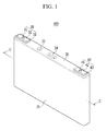
FIG. 1 is a perspective view illustrating a rechargeable battery according to a first exemplary embodiment of the present invention. -
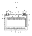
FIG. 2 is a cross-sectional view taken along line II-II ofFIG. 1 . -
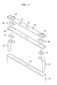
FIG. 3 is an exploded perspective view of the rechargeable battery according to the first exemplary embodiment of the present invention. -
FIG. 4 is a perspective view illustrating a state in which an absorption member and a cap plate according to the first exemplary embodiment of the present invention are coupled with each other. -
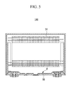
FIG. 5 is a cross-sectional view illustrating a state in which a residual electrolytic solution in the rechargeable battery ofFIG. 2 is absorbed in the absorption member. -
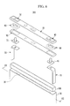
FIG. 6 is an exploded perspective view of a rechargeable battery according to a second exemplary embodiment of the present invention. -
FIG. 7 is a cross-sectional view illustrating a state in which a residual electrolytic solution in the rechargeable battery taken along line VII-VII ofFIG. 6 is absorbed in an absorption member. -
FIG. 8 is an exploded perspective view of a rechargeable battery according to a third exemplary embodiment of the present invention. -
FIG. 9 is a cross-sectional view illustrating a state in which a residual electrolytic solution in the rechargeable battery taken along line IX-IX ofFIG. 8 is absorbed in an absorption member. -
FIG. 10 is a cross-sectional view illustrating a state in which the residual electrolytic solution in the rechargeable battery taken along line IX-IX ofFIG. 8 is absorbed in the absorption member. - Hereinafter, the present invention will be described more fully hereinafter with reference to the accompanying drawings, in which exemplary embodiments of the invention are shown.
-
FIG. 1 is a perspective view illustrating a rechargeable battery according to a first exemplary embodiment of the present invention andFIG. 2 is a cross-sectional view taken along line II-II ofFIG. 1 . - Further,
FIG. 3 is an exploded perspective view of the rechargeable battery according to the first exemplary embodiment of the present invention andFIG. 4 is a perspective view illustrating a state in which an absorption member and a cap plate according to the first exemplary embodiment of the present invention are coupled with each other. -
FIG. 5 is a cross-sectional view illustrating a state in which a residual electrolytic solution in the rechargeable battery ofFIG. 2 is absorbed in an absorption member. - Referring to
FIGS. 1 and2 , arechargeable battery 100 according to the first exemplary embodiment of the present invention includes anelectrode assembly 10, acase 25 in which theelectrode assembly 10 is embedded, afirst terminal part 30 and asecond terminal part 40 that are electrically connected with theelectrode assembly 10, acap plate 20, first and secondlower insulating members solution absorption member 90, or short "absorption member" 90 that is coupled with thecap plate 20. - The
rechargeable battery 100 according to the first exemplary embodiment of the present invention is a lithium ion rechargeable battery and will be described as a squared rechargeable battery, by way of example. However, the exemplary embodiment of the present invention is not limited thereto, but may be applied to a battery, such as a lithium polymer battery, and the like. - The
electrode assembly 10 according to the exemplary embodiment of the present invention has a jelly roll form in which thefirst electrode 11, thesecond electrode 12, and a separator are wound therearound. - Further, a surface of the
electrode assembly 10 according to the exemplary embodiment of the present invention may be coupled with aninsulating tape 14 to insulate theelectrode assembly 10 from thecase 25. - Herein, according to the exemplary embodiment of the present invention, the
first electrode 11 is a negative electrode and thesecond electrode 12 is a positive electrode. - However, the exemplary embodiment of the present invention is not limited thereto, but the
first electrode 11 may be used as a positive electrode and thesecond electrode 12 may be as a negative electrode. - The
first electrode 11 is wound to be disposed at an outermost side of theelectrode assembly 10 according to the exemplary embodiment of the present invention. - In addition, the
first electrode 11 and thesecond electrode 12 are partitioned into a coated part in which a current collector is coated with an active material and a first electrode uncoatedpart 11a and a second electrode uncoatedpart 12a that are each disposed at both sides of the coating part in the jelly roll state without the current collector not being coated with the active material. - The first electrode uncoated
part 11a of theelectrode assembly 10 is electrically connected with thefirst terminal part 30 via a first electrodecurrent collecting member 50 and the second electrode uncoatedpart 12a is electrically connected with thesecond terminal part 40 via a second electrodecurrent collecting member 70. - Further, the first and
second terminal parts second rivets second terminal plates terminal insulating member 33 that is disposed between thefirst terminal plate 32 and thecap plate 20, asecond connection plate 43 that is disposed between thesecond terminal plate 42 and thecap plate 20, and first andsecond gaskets - Herein, the second
terminal plate 42 according to the exemplary embodiment of the present invention is made of a conductive material. - In addition, the
cap plate 20 according to the exemplary embodiment of the present invention has a thin panel shape and is made of a conductive material and coupled with an opening of thecase 25 to seal the opening. - The
cap plate 20 is provided with anelectrolyte injection port 21 through which an electrolytic solution is injected into the sealedcase 25 and theelectrolyte injection port 21 injects the electrolytic solution and then is sealed by a sealingstopper 22. - The
cap plate 20 is provided with avent hole 23 that is provided with avent plate 24 fractured when an internal pressure of the sealedcase 25 is above a predetermined pressure. - The
cap plate 20 according to the exemplary embodiment of the present invention may be electrically connected with thesecond electrode 12 via the secondterminal plate 42, thesecond connection plate 43, and the second electrodecurrent collecting member 70. - The
case 25 has a substantially rectangular parallelepiped shape and is made of a conductive material and one surface of thecase 25 is provided with an opening through which theelectrode assembly 10 is inserted. - In addition, the
case 25 according to the exemplary embodiment of the present invention may be electrically connected with thesecond electrode 12 via thecap plate 20. - However, the exemplary embodiment of the present invention is not limited thereto, but the case may be formed in various shapes, such as a cylindrical shape, a pouch shape, and the like.
- Further, the first and second lower insulating
members cap plate 20 within thecase 25. - Referring to
FIGS. 3 and4 , theabsorption member 90 according to the exemplary embodiment of the present invention is coupled with one surface of thecap plate 20 that faces the inside of thecase 25. - The
absorption member 90 according to the exemplary embodiment of the present invention has a thin plate shape and is made of an absorbing material and an insulating material. - In addition, the absorbing
member 90 according to the exemplary embodiment of the present invention includes afirst groove 91, asecond groove 92, athird groove 93, and afourth groove 94. - In more detail, the
first groove 91 of the absorbingmember 90 according to the exemplary embodiment of the present invention is coupled with the first lower insulatingmember 60 and thesecond groove 92 is coupled with the second lower insulatingmember 80. - Further, the third groove or electrolyte
injection port groove 93 of the absorbingmember 90 according to the exemplary embodiment of the present invention is formed at a place facing theelectrolyte injection port 21 so that theelectrolyte injection port 21 is exposed within thecase 25. - In addition, the fourth groove or vent
hole groove 94 of the absorbingmember 90 according to the exemplary embodiment of the present invention is formed at a place facing thevent hole 23 so that thevent hole 23 is exposed within thecase 25. - Hereinafter, the case in which a residual electrolytic solution E is absorbed in the absorbing
member 90 to prevent a short circuit will be described in detail. -
FIG. 3 is a cross-sectional view illustrating the state in which the residual electrolytic solution in the rechargeable battery ofFIG. 2 is absorbed in the absorption member. - Referring to
FIG. 3 , theabsorption member 90 according to the exemplary embodiment of the present invention may be coupled with one surface of thecap plate 20 facing theelectrode assembly 10 to be disposed between theelectrode assembly 10 and thecap plate 20. - In order to smoothly operate the
electrode assembly 10, an appropriate amount of the electrolytic solution needs to be filled or inserted into theelectrode assembly 10. - Therefore, the amount of the electrolytic solution injected into the
case 25 may be more than the amount of the electrolytic solution appropriately filled into theelectrode assembly 10. - Herein, when the amount of the electrolytic solution injected into the
case 25 is more than the amount of the electrolytic solution appropriately filled into theelectrode assembly 10, as illustrated inFIG. 2 , the residual electrolytic solution E that is not contained within theelectrode assembly 10 is generated within thecase 25. - Herein, the residual electrolytic solution E may be a factor that causes a short circuit within the
case 25. - That is, the
first electrode 11 is disposed at an outermost side of theelectrode assembly 10 according to the exemplary embodiment of the present invention and thecase 25 is electrically connected with thesecond electrode 12 via thecap plate 20. - Further, the residual electrolytic solution E is disposed between the
first electrode 11 and a bottom surface of thecase 25. - In this case, the
first electrode 11 and thecase 25 may keep the state in which thefirst electrode 11 and thecase 25 are not electrically connected with each other by the insulatingtape 14, that is, the insulating state. - However, the insulating
tape 14 that is coupled with the surface of theelectrode assembly 10 may be damaged due to external impact, heat generated from the inside of thecase 25, and the like. - Therefore, when the insulating
tape 14 is damaged due to external impact, and the like, so that thefirst electrode 11 is electrically connected with thecase 25 via the residual electrolytic solution E that is stagnated in the bottom of thecase 25 disposed at a side facing thecap plate 20, a current path is formed between thefirst electrode 11 and the second electrode to cause a short circuit within thecase 25. - The
absorption member 90 according to the exemplary embodiment of the present invention may prevent the short circuit from occurring within thecase 25 due to the residual electrolyte solution E. - In more detail, as illustrated in
FIG. 3 , when thecase 25 rotates clockwise or counterclockwise so that thecap plate 20 faces a gravity direction (in other words: a normal to thecap plate 20 pointing away from thecase 25 is parallel to the direction of gravity), the residual electrolytic solution E remaining in thecase 25 is absorbed in theabsorption member 90 disposed in thecase 25. - In this case, the
absorption member 90 according to the exemplary embodiment of the present invention is made of a material that may appropriately absorb the electrolytic solution. - Consequently, according to the exemplary embodiment of the present invention, since the residual electrolytic solution E is absorbed in the
absorption member 90, it is possible to prevent a short circuit from occurring within thecase 25 by the residual electrolytic solution E even when the insulatingtape 14 is damaged. - Further, in order to prevent the residual electrolytic solution E from occurring within the
case 25, the electrolytic solution as much as the amount of the electrolytic solution appropriately filled into theelectrode assembly 10 may be injected into thecase 25. - However, in order to inject the electrolytic solution into the
case 25 in the amount of electrolytic solution appropriately filled into theelectrode assembly 10, there is a need to stop injecting the electrolytic solution and then measure the amount of the electrolytic solution supplied into thecase 25. - Therefore, in order to prevent the residual electrolytic solution E from occurring within the
case 25, the injection of the electrolytic solution needs to stop or the injection speed of the electrolytic solution needs to be delayed, such that an injection process time of the electrolytic solution may be increased. - However, according to the exemplary embodiment of the present invention, there is no need to measure the injected amount of the electrolytic solution enough to prevent the residual electrolytic solution E from occurring within the
case 25. - That is, according to the exemplary embodiment of the present invention, even though the residual electrolytic solution E is generated due to the supply of the electrolytic solution into the
case 25, the residual electrolytic solution E may be removed by theabsorption member 90, such that there is no need to measure the injected amount of the electrolytic solution as in the state of the art. - The absorption member is preferably attached to the cap plate via an adhesive Furthermore, the absorption member comprises or consists of an electrolyte solution absorbing material. The electrolyte solution absorption member may comprise a porous film or a fiber fabric. The porous film and the fiber fabric may be formed of at least one of porous materials. They may have a plurality of nano-size openings to absorb and contain an electrolyte solution therein. Specifically, the porous film may be formed of at least one of polyolefin and poly vinylindene fluoride.
- Therefore, according to the exemplary embodiment of the present invention, in order to measure the injected amount of the electrolytic solution, there is no need to stop injecting the electrolytic solution or delay the injection speed of the electrolytic solution, such that the injection process time of the electrolytic solution is shortened, thereby improving the productivity of the rechargeable battery.
-
FIG. 6 is an exploded perspective view of a rechargeable battery according to a second exemplary embodiment of the present invention andFIG. 7 is a cross-sectional view illustrating a state in which a residual electrolytic solution in the rechargeable battery taken along line VII-VII ofFIG. 6 is absorbed in an absorption member. - Referring to
FIGS. 6 and7 , arechargeable battery 200 according to the exemplary embodiment of the present invention has the same configuration as therechargeable battery 100 according to the first exemplary embodiment of the present invention, except for anauxiliary absorption member 190. - Therefore, the detailed description of the same components as those of the
rechargeable battery 100 according to the first exemplary embodiment of the present invention will be omitted below. - The
auxiliary absorption member 190 according to the exemplary embodiment of the present invention is coupled with a side within thecase 25. - In more detail, the
auxiliary absorption member 190 is coupled with a first portion S2 of the inner side of thecase 25 that is disposed above a first or upper surface S1 of theelectrode assembly 10 facing thecap plate 20. - The electrolytic solution injected through the
electrolyte injection port 21 may be filled up to the first surface S1 of theelectrode assembly 10 within thecase 25. - Therefore, the electrolytic solution is not absorbed in the
auxiliary absorption member 190 coupled with the first portion S2 of thecase 25 that is disposed above the first surface S1 of theelectrode assembly 10 during the injection of the electrolytic solution. - As illustrated in
FIG. 7 , when thecase 25 rotates clockwise or counterclockwise so that thecap plate 20 faces a gravity direction (in other words: a normal to thecap plate 20 pointing away from thecase 25 is parallel to the direction of gravity), the residual electrolytic solution E remaining in thecase 25 may be absorbed in theabsorption member 90 and theauxiliary absorption member 190 disposed in thecase 25. - In this case, when the
case 25 rotates clockwise or counterclockwise, the residual electrolytic solution E flows down along a side wall within thecase 25. - Therefore, the residual electrolytic solution E is primarily absorbed in the
auxiliary absorption member 190 coupled with the first portion S2 of the side wall within thecase 25 and the residual electrolytic solution E that is not absorbed in theauxiliary absorption member 190 is absorbed in theabsorption member 90. - Consequently, the residual electrolytic solution E within the
case 25 may be quickly removed by theauxiliary absorption member 190 according to the exemplary embodiment of the present invention. - Further, according to the exemplary embodiment of the present invention, a large amount of residual electrolytic solution E may be removed by the
absorption member 90 and theauxiliary absorption member 190. - Therefore, according to the exemplary embodiment of the present invention, it is possible to prevent the short circuit from occurring within the case 5 due to the residual electrolytic solution E and the injection process time of the electrolytic solution may be shortened, thereby improving the productivity of the rechargeable battery.
-
FIG. 8 is an exploded perspective view of a rechargeable battery according to a third exemplary embodiment of the present invention,FIG. 9 is a cross-sectional view illustrating a state in which a residual electrolytic solution in the rechargeable battery taken along line IX-IX ofFIG. 8 is absorbed in an absorption member, andFIG. 10 is a cross-sectional view illustrating a state in which the residual electrolytic solution in the rechargeable battery taken along line IX-IX ofFIG. 8 is absorbed in the absorption member. - Referring to
FIGS. 8 to 10 , arechargeable battery 300 according to the exemplary embodiment of the present invention has the same configuration as therechargeable battery 100 according to the first exemplary embodiment of the present invention, except for anabsorption member 290. - Therefore, the detailed description of the same components as those of the
rechargeable battery 100 according to the first exemplary embodiment of the present invention will be omitted below. - Referring to
FIG. 8 , theabsorption member 290 according to the exemplary embodiment of the present invention includes afirst groove 291, asecond groove 292, athird groove 293, afourth groove 294, a protrudingpart 295, and aflat part 296. In order to demonstrate the shape of theabsorption member 290, thecap plate 20 together with theabsorption member 290 inFig. 8 is turned upside down. Thus, for assembly of thebattery 300, the upper side of theabsorption member 290 as shown inFig. 8 becomes the lower side of theabsorption member 290 facing theelectrode assembly 10 after assembly. - Herein, the first to
fourth grooves fourth grooves fourth grooves - According to the exemplary embodiment of the present invention, the
flat part 296 is provided with thefirst groove 291, thesecond groove 292, the third groove or electrolyteinjection port groove 293, and the fourth groove or venthole groove 294 and one surface of theflat part 296 is coupled with one surface of thecap plate 20 facing the inside of thecase 25. - Further, the protruding
part 295 according to the exemplary embodiment of the present invention protrudes along an edge of theflat part 296. - In more detail, the protruding
part 295 according to the exemplary embodiment of the present invention protrudes, forming a closed curve along an edge of theflat part 296. - In this case, the protruding
part 295 may protrude by forming a predetermined angle with respect to theflat part 296. - According to the exemplary embodiment of the present invention, when the
cap plate 20 is coupled with the opening of thecase 25, the protrudingpart 295 coupled with thecap plate 20 faces the inside of thecase 25. - In this case, the
absorption member 290 is disposed within thecase 25 in the state in which theprotruding part 295 contacts a part of the side wall within thecase 25. - As illustrated in
FIGS. 9 and10 , when thecase 25 rotates clockwise or counterclockwise so that thecap plate 20 faces a gravity direction (in other words: a normal of thecap plate 20 pointing away from thecase 25 is parallel to the direction of gravity), the residual electrolytic solution E remaining in thecase 25 may be absorbed in theabsorption member 290 disposed in thecase 25. - In this case, when the
case 25 rotates clockwise or counterclockwise, the residual electrolytic solution E flows down along the side wall within thecase 25. - Therefore, the residual electrolytic solution E is primarily absorbed in the
protruding part 295 of theabsorption member 290 contacting the side wall within thecase 25 and the residual electrolytic solution E that is not absorbed in theprotruding part 295 is absorbed in theflat part 296 of theabsorption member 290. - Consequently, according to the exemplary embodiment of the present invention, the residual electrolytic solution E flowing down along the side wall within the
case 25 may be quickly removed by the protrudingpart 295 of theabsorption member 290. - Further, according to the exemplary embodiment of the present invention, a large amount of residual electrolytic solution E may be removed by the protruding
part 295 and theflat part 296 of theabsorption member 290. - Therefore, according to the exemplary embodiment of the present invention, it is possible to prevent the short circuit from occurring within the case 5 due to the residual electrolytic solution E and the injection process time of the electrolytic solution may be shortened, thereby improving the productivity of the rechargeable battery.
Claims (15)
- Rechargeable battery (100) comprising:an electrode assembly (10),a case (25) for mounting the electrode assembly (10) and an electrolyte solution therein,a cap plate (20) for closing an opening of the case (25),characterized in thatan electrolyte solution absorption member (90) is provided inside the case (25) coupled to the cap plate (20).
- The rechargeable battery (100) of claim 1, wherein the electrolyte solution absorption member (90) is provided on the surface of the cap plate (20) facing the electrode assembly (10), preferably attached to the cap plate (20) via an adhesive.
- The rechargeable battery (100) of one of the previous claims, wherein the electrolyte solution absorption member (90) comprises or consists of an electrolyte solution absorbing material.
- The rechargeable battery (100) of one of the previous claims, wherein the electrolyte solution absorption member (90) is an absorption sheet.
- The rechargeable battery (100) of one of the previous claims, further comprising a first terminal rivet (31) coupled to a first electrode (11) of the electrode assembly (10) and protruding from the inside of the case (25) through the cap plate (20) and the electrolyte solution absorption member (90) comprises a first groove (91) for passing the first terminal rivet (31) therethrough.
- The rechargeable battery (100) of claim 5, further comprising a second terminal rivet (41) coupled to a second electrode (12) of the electrode assembly (10) and protruding from the inside of the case (25) through the cap plate (20) and the electrolyte solution absorption member (90) comprise a second groove (92) for passing the second terminal rivet (41) therethrough.
- The rechargeable battery (100) of one of the previous claims, wherein the cap plate (20) comprises an electrolyte injection port (21) and the electrolyte solution absorption member (90) comprises a electrolyte injection port groove (93) formed at a location corresponding to the location of the electrolyte injection port (21).
- The rechargeable battery (100) of one of the previous claims, wherein the cap plate (20) comprises an vent hole (23) and the electrolyte solution absorption member (90) comprises a vent hole groove (94) formed at a location corresponding to the location of the vent hole (23).
- The rechargeable battery (100) of one of the previous claims, further comprising an auxiliary electrolyte solution absorption member (190) coupled to at least one side surface of the case (25) at a vertical location above the electrode assembly (10) and below the cap plate (25).
- The rechargeable battery (100) of claim 9, wherein the auxiliary electrolyte solution absorption member (190) comprises an electrolyte solution absorbing material.
- The rechargeable battery (100) of claim 9 or 10, wherein the auxiliary electrolyte solution absorption member (190) has the shape of a ring or a shape corresponding to a lateral cross section of the case (25) and fixed or laminated to the interior of the case (25).
- The rechargeable battery (100) of one of the previous claims, wherein the electrolyte solution absorption member (290) comprises a flat part (296) and a protruding part (295) protruding in a direction away from the cap plate (25) towards the electrode assembly (10).
- The rechargeable battery (100) of claim 12, wherein the protruding part (295) protrudes along an edge of the flat part (296), wherein the flat part (296) is coupled to the cap plate (25).
- The rechargeable battery (100) of claim 13, wherein the protruding part (295) forms a closed curve on the edge of the flat part (296).
- The rechargeable battery (100) of claim 14, wherein an inner circumference of the protruding part (295) is angled with respect to the flat part (296).
Applications Claiming Priority (2)
| Application Number | Priority Date | Filing Date | Title |
|---|---|---|---|
| US201361809798P | 2013-04-08 | 2013-04-08 | |
| US14/054,533 US20140302361A1 (en) | 2013-04-08 | 2013-10-15 | Rechargeable battery |
Publications (2)
| Publication Number | Publication Date |
|---|---|
| EP2790245A1 true EP2790245A1 (en) | 2014-10-15 |
| EP2790245B1 EP2790245B1 (en) | 2019-08-14 |
Family
ID=49713002
Family Applications (1)
| Application Number | Title | Priority Date | Filing Date |
|---|---|---|---|
| EP13196066.8A Active EP2790245B1 (en) | 2013-04-08 | 2013-12-06 | Rechargeable battery |
Country Status (5)
| Country | Link |
|---|---|
| US (1) | US20140302361A1 (en) |
| EP (1) | EP2790245B1 (en) |
| JP (1) | JP6346449B2 (en) |
| KR (1) | KR20140121759A (en) |
| CN (1) | CN104103853B (en) |
Families Citing this family (6)
| Publication number | Priority date | Publication date | Assignee | Title |
|---|---|---|---|---|
| KR102422513B1 (en) * | 2016-10-24 | 2022-07-20 | 삼성에스디아이 주식회사 | Secondary Battery |
| KR102554098B1 (en) * | 2019-01-17 | 2023-07-12 | 삼성전자주식회사 | Housing, manufacturing method thereof, and electronic device including the same |
| CN111029489B (en) | 2019-08-14 | 2021-08-17 | 宁德时代新能源科技股份有限公司 | Secondary battery |
| CN111029488B (en) * | 2019-08-14 | 2021-07-30 | 宁德时代新能源科技股份有限公司 | Secondary battery |
| CN115051019A (en) * | 2022-06-28 | 2022-09-13 | 蔚来汽车科技(安徽)有限公司 | Battery cell packaging method and battery cell packaging system |
| KR20250114121A (en) * | 2023-04-17 | 2025-07-28 | 컨템포러리 엠퍼렉스 테크놀로지 씨오., 리미티드 | Battery cells, batteries and electrical devices |
Citations (5)
| Publication number | Priority date | Publication date | Assignee | Title |
|---|---|---|---|---|
| US4788112A (en) * | 1987-08-17 | 1988-11-29 | Kung Chin Chung | Rechargeable storage battery |
| KR20060085443A (en) * | 2005-01-24 | 2006-07-27 | 삼성에스디아이 주식회사 | Secondary battery |
| JP2007012485A (en) * | 2005-06-30 | 2007-01-18 | Sanyo Electric Co Ltd | Battery with cap and power supply |
| KR20080058966A (en) * | 2006-12-23 | 2008-06-26 | 주식회사 엘지화학 | Battery containing electrolyte suction washer |
| US20110143178A1 (en) * | 2009-12-15 | 2011-06-16 | Chang-Bum Ahn | Secondary battery |
Family Cites Families (24)
| Publication number | Priority date | Publication date | Assignee | Title |
|---|---|---|---|---|
| US3537902A (en) * | 1964-10-29 | 1970-11-03 | Yuasa Batttery Co Ltd | Semi-sealed type storage battery |
| US3442709A (en) * | 1965-10-13 | 1969-05-06 | Fuji Electrochemical Co Ltd | Layer-built alkaline cell |
| JPS591337Y2 (en) * | 1978-03-31 | 1984-01-14 | 新神戸電機株式会社 | Sealed storage battery |
| CN2225723Y (en) * | 1995-01-15 | 1996-04-24 | 江中道 | Sealed lead acid secondary accumulator without maintenance |
| JPH1186897A (en) * | 1997-09-02 | 1999-03-30 | Toyota Autom Loom Works Ltd | Sealed nickel hydrogen battery |
| JP4248044B2 (en) * | 1998-03-18 | 2009-04-02 | 三洋電機株式会社 | Non-aqueous electrolyte secondary battery |
| JP2000082490A (en) * | 1998-09-08 | 2000-03-21 | Toshiba Battery Co Ltd | Alkaline secondary battery |
| JP2001216946A (en) * | 2000-01-31 | 2001-08-10 | Sony Corp | Battery |
| CN1198346C (en) * | 2000-03-14 | 2005-04-20 | 松下电器产业株式会社 | Secondary battery, wire bonding method thereof, and battery power supply device using the same |
| JP2003346894A (en) * | 2002-05-27 | 2003-12-05 | Sanyo Electric Co Ltd | Alkaline storage battery |
| JP4352707B2 (en) * | 2003-01-21 | 2009-10-28 | ソニーケミカル&インフォメーションデバイス株式会社 | Liquid absorbing composition, liquid absorbing sheet and non-aqueous electrolyte battery pack |
| TWI280677B (en) * | 2003-02-18 | 2007-05-01 | Sony Chemicals & Information D | Liquid absorbing sheet and nonaqueous electrolyte battery pack |
| JP3873931B2 (en) * | 2003-05-30 | 2007-01-31 | ソニーケミカル&インフォメーションデバイス株式会社 | Absorbent sheet and non-aqueous electrolyte battery pack |
| JP2008166191A (en) * | 2006-12-28 | 2008-07-17 | Sanyo Electric Co Ltd | Battery pack |
| KR100973313B1 (en) * | 2008-03-28 | 2010-07-30 | 삼성에스디아이 주식회사 | Protective circuit board and battery pack having same |
| JP5481827B2 (en) * | 2008-10-15 | 2014-04-23 | 株式会社Gsユアサ | battery |
| KR101023104B1 (en) * | 2008-12-26 | 2011-03-24 | 에스비리모티브 주식회사 | Secondary battery |
| JP5561848B2 (en) * | 2009-07-13 | 2014-07-30 | トヨタ自動車株式会社 | Batteries, vehicles, and equipment using batteries |
| US8440336B2 (en) * | 2009-12-08 | 2013-05-14 | Samsung Sdi Co., Ltd. | Rechargeable battery with short circuit member |
| WO2011070816A1 (en) * | 2009-12-11 | 2011-06-16 | 栗田工業株式会社 | Nonaqueous electrolyte secondary battery material, and nonaqueous electrolyte secondary battery using same |
| US9343772B2 (en) * | 2010-10-08 | 2016-05-17 | Samsung Sdi Co., Ltd. | Rechargeable battery |
| KR102059205B1 (en) * | 2011-01-31 | 2019-12-24 | 가부시키가이샤 지에스 유아사 | Electric storage element and method for manufacturing same |
| CN102683735B (en) * | 2011-03-16 | 2017-03-01 | 株式会社杰士汤浅国际 | Charge storage element |
| JP5673314B2 (en) * | 2011-04-08 | 2015-02-18 | 日産自動車株式会社 | Secondary battery and case assembly and assembled battery using the same |
-
2013
- 2013-10-15 US US14/054,533 patent/US20140302361A1/en not_active Abandoned
- 2013-11-04 KR KR1020130133058A patent/KR20140121759A/en not_active Ceased
- 2013-12-06 EP EP13196066.8A patent/EP2790245B1/en active Active
-
2014
- 2014-01-31 JP JP2014016583A patent/JP6346449B2/en active Active
- 2014-03-05 CN CN201410077674.1A patent/CN104103853B/en active Active
Patent Citations (5)
| Publication number | Priority date | Publication date | Assignee | Title |
|---|---|---|---|---|
| US4788112A (en) * | 1987-08-17 | 1988-11-29 | Kung Chin Chung | Rechargeable storage battery |
| KR20060085443A (en) * | 2005-01-24 | 2006-07-27 | 삼성에스디아이 주식회사 | Secondary battery |
| JP2007012485A (en) * | 2005-06-30 | 2007-01-18 | Sanyo Electric Co Ltd | Battery with cap and power supply |
| KR20080058966A (en) * | 2006-12-23 | 2008-06-26 | 주식회사 엘지화학 | Battery containing electrolyte suction washer |
| US20110143178A1 (en) * | 2009-12-15 | 2011-06-16 | Chang-Bum Ahn | Secondary battery |
Also Published As
| Publication number | Publication date |
|---|---|
| EP2790245B1 (en) | 2019-08-14 |
| JP6346449B2 (en) | 2018-06-20 |
| KR20140121759A (en) | 2014-10-16 |
| CN104103853A (en) | 2014-10-15 |
| JP2014203822A (en) | 2014-10-27 |
| US20140302361A1 (en) | 2014-10-09 |
| CN104103853B (en) | 2019-09-06 |
Similar Documents
| Publication | Publication Date | Title |
|---|---|---|
| EP2541650B1 (en) | Rechargeable battery having improved gasket and terminal structure | |
| KR102201306B1 (en) | Secondary Battery | |
| US11424508B2 (en) | Rechargeable battery | |
| KR102507879B1 (en) | Rechargeable battery module | |
| KR101254886B1 (en) | Secondary battery | |
| KR102165332B1 (en) | Secondary battery | |
| CN106450407B (en) | Secondary battery | |
| US9209493B2 (en) | Battery pack | |
| CN106356490B (en) | Rechargeable battery and battery module including rechargeable battery | |
| EP2790245B1 (en) | Rechargeable battery | |
| KR102211365B1 (en) | Secondary battery | |
| JP2011222469A (en) | Secondary battery | |
| CN104953075A (en) | Secondary battery | |
| KR102211174B1 (en) | Rechargeable battery | |
| KR102819179B1 (en) | Secondary battery | |
| CN103943809A (en) | Secondary battery | |
| CN114784433A (en) | Rechargeable battery pack | |
| KR20140067246A (en) | Battery cell having nozzle member | |
| KR20160045468A (en) | Pouch type secondary battery and a method of making the same | |
| KR20140030431A (en) | Secondary battery having case with multi electrode assembly-receiving portion | |
| KR20170001443A (en) | Secondary battery | |
| KR101297014B1 (en) | Secondary battery | |
| KR20130065574A (en) | Secondary battery | |
| KR20120040447A (en) | Secondary battery of improved insulating properties | |
| CN110718668A (en) | Rechargeable Batteries and Battery Modules |
Legal Events
| Date | Code | Title | Description |
|---|---|---|---|
| PUAI | Public reference made under article 153(3) epc to a published international application that has entered the european phase |
Free format text: ORIGINAL CODE: 0009012 |
|
| 17P | Request for examination filed |
Effective date: 20131206 |
|
| AK | Designated contracting states |
Kind code of ref document: A1 Designated state(s): AL AT BE BG CH CY CZ DE DK EE ES FI FR GB GR HR HU IE IS IT LI LT LU LV MC MK MT NL NO PL PT RO RS SE SI SK SM TR |
|
| AX | Request for extension of the european patent |
Extension state: BA ME |
|
| R17P | Request for examination filed (corrected) |
Effective date: 20150414 |
|
| RBV | Designated contracting states (corrected) |
Designated state(s): AL AT BE BG CH CY CZ DE DK EE ES FI FR GB GR HR HU IE IS IT LI LT LU LV MC MK MT NL NO PL PT RO RS SE SI SK SM TR |
|
| STAA | Information on the status of an ep patent application or granted ep patent |
Free format text: STATUS: EXAMINATION IS IN PROGRESS |
|
| 17Q | First examination report despatched |
Effective date: 20170830 |
|
| GRAP | Despatch of communication of intention to grant a patent |
Free format text: ORIGINAL CODE: EPIDOSNIGR1 |
|
| STAA | Information on the status of an ep patent application or granted ep patent |
Free format text: STATUS: GRANT OF PATENT IS INTENDED |
|
| INTG | Intention to grant announced |
Effective date: 20190215 |
|
| GRAS | Grant fee paid |
Free format text: ORIGINAL CODE: EPIDOSNIGR3 |
|
| GRAJ | Information related to disapproval of communication of intention to grant by the applicant or resumption of examination proceedings by the epo deleted |
Free format text: ORIGINAL CODE: EPIDOSDIGR1 |
|
| GRAL | Information related to payment of fee for publishing/printing deleted |
Free format text: ORIGINAL CODE: EPIDOSDIGR3 |
|
| STAA | Information on the status of an ep patent application or granted ep patent |
Free format text: STATUS: EXAMINATION IS IN PROGRESS |
|
| GRAR | Information related to intention to grant a patent recorded |
Free format text: ORIGINAL CODE: EPIDOSNIGR71 |
|
| STAA | Information on the status of an ep patent application or granted ep patent |
Free format text: STATUS: GRANT OF PATENT IS INTENDED |
|
| GRAA | (expected) grant |
Free format text: ORIGINAL CODE: 0009210 |
|
| STAA | Information on the status of an ep patent application or granted ep patent |
Free format text: STATUS: THE PATENT HAS BEEN GRANTED |
|
| INTC | Intention to grant announced (deleted) | ||
| INTG | Intention to grant announced |
Effective date: 20190704 |
|
| AK | Designated contracting states |
Kind code of ref document: B1 Designated state(s): AL AT BE BG CH CY CZ DE DK EE ES FI FR GB GR HR HU IE IS IT LI LT LU LV MC MK MT NL NO PL PT RO RS SE SI SK SM TR |
|
| REG | Reference to a national code |
Ref country code: GB Ref legal event code: FG4D |
|
| REG | Reference to a national code |
Ref country code: CH Ref legal event code: EP Ref country code: AT Ref legal event code: REF Ref document number: 1168076 Country of ref document: AT Kind code of ref document: T Effective date: 20190815 |
|
| REG | Reference to a national code |
Ref country code: DE Ref legal event code: R096 Ref document number: 602013059088 Country of ref document: DE |
|
| REG | Reference to a national code |
Ref country code: IE Ref legal event code: FG4D |
|
| REG | Reference to a national code |
Ref country code: NL Ref legal event code: MP Effective date: 20190814 |
|
| REG | Reference to a national code |
Ref country code: LT Ref legal event code: MG4D |
|
| PG25 | Lapsed in a contracting state [announced via postgrant information from national office to epo] |
Ref country code: NL Free format text: LAPSE BECAUSE OF FAILURE TO SUBMIT A TRANSLATION OF THE DESCRIPTION OR TO PAY THE FEE WITHIN THE PRESCRIBED TIME-LIMIT Effective date: 20190814 Ref country code: HR Free format text: LAPSE BECAUSE OF FAILURE TO SUBMIT A TRANSLATION OF THE DESCRIPTION OR TO PAY THE FEE WITHIN THE PRESCRIBED TIME-LIMIT Effective date: 20190814 Ref country code: BG Free format text: LAPSE BECAUSE OF FAILURE TO SUBMIT A TRANSLATION OF THE DESCRIPTION OR TO PAY THE FEE WITHIN THE PRESCRIBED TIME-LIMIT Effective date: 20191114 Ref country code: SE Free format text: LAPSE BECAUSE OF FAILURE TO SUBMIT A TRANSLATION OF THE DESCRIPTION OR TO PAY THE FEE WITHIN THE PRESCRIBED TIME-LIMIT Effective date: 20190814 Ref country code: PT Free format text: LAPSE BECAUSE OF FAILURE TO SUBMIT A TRANSLATION OF THE DESCRIPTION OR TO PAY THE FEE WITHIN THE PRESCRIBED TIME-LIMIT Effective date: 20191216 Ref country code: LT Free format text: LAPSE BECAUSE OF FAILURE TO SUBMIT A TRANSLATION OF THE DESCRIPTION OR TO PAY THE FEE WITHIN THE PRESCRIBED TIME-LIMIT Effective date: 20190814 Ref country code: FI Free format text: LAPSE BECAUSE OF FAILURE TO SUBMIT A TRANSLATION OF THE DESCRIPTION OR TO PAY THE FEE WITHIN THE PRESCRIBED TIME-LIMIT Effective date: 20190814 Ref country code: NO Free format text: LAPSE BECAUSE OF FAILURE TO SUBMIT A TRANSLATION OF THE DESCRIPTION OR TO PAY THE FEE WITHIN THE PRESCRIBED TIME-LIMIT Effective date: 20191114 |
|
| REG | Reference to a national code |
Ref country code: AT Ref legal event code: MK05 Ref document number: 1168076 Country of ref document: AT Kind code of ref document: T Effective date: 20190814 |
|
| PG25 | Lapsed in a contracting state [announced via postgrant information from national office to epo] |
Ref country code: LV Free format text: LAPSE BECAUSE OF FAILURE TO SUBMIT A TRANSLATION OF THE DESCRIPTION OR TO PAY THE FEE WITHIN THE PRESCRIBED TIME-LIMIT Effective date: 20190814 Ref country code: RS Free format text: LAPSE BECAUSE OF FAILURE TO SUBMIT A TRANSLATION OF THE DESCRIPTION OR TO PAY THE FEE WITHIN THE PRESCRIBED TIME-LIMIT Effective date: 20190814 Ref country code: GR Free format text: LAPSE BECAUSE OF FAILURE TO SUBMIT A TRANSLATION OF THE DESCRIPTION OR TO PAY THE FEE WITHIN THE PRESCRIBED TIME-LIMIT Effective date: 20191115 Ref country code: IS Free format text: LAPSE BECAUSE OF FAILURE TO SUBMIT A TRANSLATION OF THE DESCRIPTION OR TO PAY THE FEE WITHIN THE PRESCRIBED TIME-LIMIT Effective date: 20191214 Ref country code: ES Free format text: LAPSE BECAUSE OF FAILURE TO SUBMIT A TRANSLATION OF THE DESCRIPTION OR TO PAY THE FEE WITHIN THE PRESCRIBED TIME-LIMIT Effective date: 20190814 Ref country code: AL Free format text: LAPSE BECAUSE OF FAILURE TO SUBMIT A TRANSLATION OF THE DESCRIPTION OR TO PAY THE FEE WITHIN THE PRESCRIBED TIME-LIMIT Effective date: 20190814 |
|
| PG25 | Lapsed in a contracting state [announced via postgrant information from national office to epo] |
Ref country code: TR Free format text: LAPSE BECAUSE OF FAILURE TO SUBMIT A TRANSLATION OF THE DESCRIPTION OR TO PAY THE FEE WITHIN THE PRESCRIBED TIME-LIMIT Effective date: 20190814 |
|
| PG25 | Lapsed in a contracting state [announced via postgrant information from national office to epo] |
Ref country code: DK Free format text: LAPSE BECAUSE OF FAILURE TO SUBMIT A TRANSLATION OF THE DESCRIPTION OR TO PAY THE FEE WITHIN THE PRESCRIBED TIME-LIMIT Effective date: 20190814 Ref country code: EE Free format text: LAPSE BECAUSE OF FAILURE TO SUBMIT A TRANSLATION OF THE DESCRIPTION OR TO PAY THE FEE WITHIN THE PRESCRIBED TIME-LIMIT Effective date: 20190814 Ref country code: AT Free format text: LAPSE BECAUSE OF FAILURE TO SUBMIT A TRANSLATION OF THE DESCRIPTION OR TO PAY THE FEE WITHIN THE PRESCRIBED TIME-LIMIT Effective date: 20190814 Ref country code: IT Free format text: LAPSE BECAUSE OF FAILURE TO SUBMIT A TRANSLATION OF THE DESCRIPTION OR TO PAY THE FEE WITHIN THE PRESCRIBED TIME-LIMIT Effective date: 20190814 Ref country code: RO Free format text: LAPSE BECAUSE OF FAILURE TO SUBMIT A TRANSLATION OF THE DESCRIPTION OR TO PAY THE FEE WITHIN THE PRESCRIBED TIME-LIMIT Effective date: 20190814 Ref country code: PL Free format text: LAPSE BECAUSE OF FAILURE TO SUBMIT A TRANSLATION OF THE DESCRIPTION OR TO PAY THE FEE WITHIN THE PRESCRIBED TIME-LIMIT Effective date: 20190814 |
|
| PG25 | Lapsed in a contracting state [announced via postgrant information from national office to epo] |
Ref country code: IS Free format text: LAPSE BECAUSE OF FAILURE TO SUBMIT A TRANSLATION OF THE DESCRIPTION OR TO PAY THE FEE WITHIN THE PRESCRIBED TIME-LIMIT Effective date: 20200224 Ref country code: SM Free format text: LAPSE BECAUSE OF FAILURE TO SUBMIT A TRANSLATION OF THE DESCRIPTION OR TO PAY THE FEE WITHIN THE PRESCRIBED TIME-LIMIT Effective date: 20190814 Ref country code: SK Free format text: LAPSE BECAUSE OF FAILURE TO SUBMIT A TRANSLATION OF THE DESCRIPTION OR TO PAY THE FEE WITHIN THE PRESCRIBED TIME-LIMIT Effective date: 20190814 Ref country code: CZ Free format text: LAPSE BECAUSE OF FAILURE TO SUBMIT A TRANSLATION OF THE DESCRIPTION OR TO PAY THE FEE WITHIN THE PRESCRIBED TIME-LIMIT Effective date: 20190814 |
|
| REG | Reference to a national code |
Ref country code: DE Ref legal event code: R097 Ref document number: 602013059088 Country of ref document: DE |
|
| PLBE | No opposition filed within time limit |
Free format text: ORIGINAL CODE: 0009261 |
|
| STAA | Information on the status of an ep patent application or granted ep patent |
Free format text: STATUS: NO OPPOSITION FILED WITHIN TIME LIMIT |
|
| PG2D | Information on lapse in contracting state deleted |
Ref country code: IS |
|
| REG | Reference to a national code |
Ref country code: CH Ref legal event code: PL |
|
| 26N | No opposition filed |
Effective date: 20200603 |
|
| REG | Reference to a national code |
Ref country code: BE Ref legal event code: MM Effective date: 20191231 |
|
| PG25 | Lapsed in a contracting state [announced via postgrant information from national office to epo] |
Ref country code: SI Free format text: LAPSE BECAUSE OF FAILURE TO SUBMIT A TRANSLATION OF THE DESCRIPTION OR TO PAY THE FEE WITHIN THE PRESCRIBED TIME-LIMIT Effective date: 20190814 Ref country code: MC Free format text: LAPSE BECAUSE OF FAILURE TO SUBMIT A TRANSLATION OF THE DESCRIPTION OR TO PAY THE FEE WITHIN THE PRESCRIBED TIME-LIMIT Effective date: 20190814 |
|
| PG25 | Lapsed in a contracting state [announced via postgrant information from national office to epo] |
Ref country code: IE Free format text: LAPSE BECAUSE OF NON-PAYMENT OF DUE FEES Effective date: 20191206 Ref country code: LU Free format text: LAPSE BECAUSE OF NON-PAYMENT OF DUE FEES Effective date: 20191206 |
|
| REG | Reference to a national code |
Ref country code: DE Ref legal event code: R079 Ref document number: 602013059088 Country of ref document: DE Free format text: PREVIOUS MAIN CLASS: H01M0002100000 Ipc: H01M0050200000 |
|
| PG25 | Lapsed in a contracting state [announced via postgrant information from national office to epo] |
Ref country code: LI Free format text: LAPSE BECAUSE OF NON-PAYMENT OF DUE FEES Effective date: 20191231 Ref country code: CH Free format text: LAPSE BECAUSE OF NON-PAYMENT OF DUE FEES Effective date: 20191231 Ref country code: BE Free format text: LAPSE BECAUSE OF NON-PAYMENT OF DUE FEES Effective date: 20191231 |
|
| PG25 | Lapsed in a contracting state [announced via postgrant information from national office to epo] |
Ref country code: CY Free format text: LAPSE BECAUSE OF FAILURE TO SUBMIT A TRANSLATION OF THE DESCRIPTION OR TO PAY THE FEE WITHIN THE PRESCRIBED TIME-LIMIT Effective date: 20190814 |
|
| PG25 | Lapsed in a contracting state [announced via postgrant information from national office to epo] |
Ref country code: HU Free format text: LAPSE BECAUSE OF FAILURE TO SUBMIT A TRANSLATION OF THE DESCRIPTION OR TO PAY THE FEE WITHIN THE PRESCRIBED TIME-LIMIT; INVALID AB INITIO Effective date: 20131206 Ref country code: MT Free format text: LAPSE BECAUSE OF FAILURE TO SUBMIT A TRANSLATION OF THE DESCRIPTION OR TO PAY THE FEE WITHIN THE PRESCRIBED TIME-LIMIT Effective date: 20190814 |
|
| PG25 | Lapsed in a contracting state [announced via postgrant information from national office to epo] |
Ref country code: MK Free format text: LAPSE BECAUSE OF FAILURE TO SUBMIT A TRANSLATION OF THE DESCRIPTION OR TO PAY THE FEE WITHIN THE PRESCRIBED TIME-LIMIT Effective date: 20190814 |
|
| P01 | Opt-out of the competence of the unified patent court (upc) registered |
Effective date: 20230528 |
|
| PGFP | Annual fee paid to national office [announced via postgrant information from national office to epo] |
Ref country code: DE Payment date: 20251126 Year of fee payment: 13 |
|
| PGFP | Annual fee paid to national office [announced via postgrant information from national office to epo] |
Ref country code: GB Payment date: 20251127 Year of fee payment: 13 |
|
| PGFP | Annual fee paid to national office [announced via postgrant information from national office to epo] |
Ref country code: FR Payment date: 20251128 Year of fee payment: 13 |