EP2789564A1 - Fixing arrangement for a light curtain in an elevator - Google Patents
Fixing arrangement for a light curtain in an elevator Download PDFInfo
- Publication number
- EP2789564A1 EP2789564A1 EP13163453.7A EP13163453A EP2789564A1 EP 2789564 A1 EP2789564 A1 EP 2789564A1 EP 13163453 A EP13163453 A EP 13163453A EP 2789564 A1 EP2789564 A1 EP 2789564A1
- Authority
- EP
- European Patent Office
- Prior art keywords
- longitudinal
- support
- support member
- fixing arrangement
- attached
- Prior art date
- Legal status (The legal status is an assumption and is not a legal conclusion. Google has not performed a legal analysis and makes no representation as to the accuracy of the status listed.)
- Granted
Links
Images


Classifications
-
- B—PERFORMING OPERATIONS; TRANSPORTING
- B66—HOISTING; LIFTING; HAULING
- B66B—ELEVATORS; ESCALATORS OR MOVING WALKWAYS
- B66B5/00—Applications of checking, fault-correcting, or safety devices in elevators
- B66B5/0006—Monitoring devices or performance analysers
- B66B5/0012—Devices monitoring the users of the elevator system
-
- B—PERFORMING OPERATIONS; TRANSPORTING
- B66—HOISTING; LIFTING; HAULING
- B66B—ELEVATORS; ESCALATORS OR MOVING WALKWAYS
- B66B13/00—Doors, gates, or other apparatus controlling access to, or exit from, cages or lift well landings
- B66B13/24—Safety devices in passenger lifts, not otherwise provided for, for preventing trapping of passengers
- B66B13/26—Safety devices in passenger lifts, not otherwise provided for, for preventing trapping of passengers between closing doors
Definitions
- the invention relates to a fixing arrangement for a light curtain in an elevator according to the preamble of claim 1.
- the elevator comprises an elevator car with a door construction comprising at least one door panel opening and closing a passage to the elevator car.
- the light curtain to be fastened with the fixing arrangement comprises a longitudinal transmitter and a longitudinal receiver facing towards each other.
- a light curtain in an elevator comprises two opposite vertical detectors at a horizontal distance from each other.
- One detector comprises a transmitter and the other detector comprises a receiver.
- the transmitter comprises a number of light emitting diodes emitting infrared light which is directed with a lens system towards the opposite receiver.
- the receiver will detect that some infrared beams are missing and this will activate a safety function which will prevent the closing of the door panels.
- the light curtain functions thus as a safety device preventing people and goods from being pressed between the door panels when the door panels are to be closed.
- the door panels will close automatically when a certain time has passed after they have opened unless the light curtain prevents closing of the door panels.
- a sliding door construction in an elevator comprises a horizontal railing, a horizontal sill and at least one door panel.
- the upper end of the at least one door panel is supported with rolls at the railing and the lower end of the at least one door panel is supported with gliding means at the sill.
- the first detector (transmitter or receiver) and the second detector (receiver of transmitter) are positioned at opposite outer ends of the railing and the sill so that the first detector and the second detector face towards each other.
- the fixing arrangement in prior art solutions comprises an L-shaped vertically extending support profile. The upper end of the support profile is attached with a bracket and a screw to the railing and the lower end of the support profile is attached in a corresponding way with a bracket and a screw to the sill. The first detector and the second detector are attached to the plane surface of the respective support profile with screws.
- the vertically between the railing and the sill extending support profile becomes rather long.
- the support profile is thus problematic to pack together with the other equipment in the door construction.
- the vertical support profile is made of one piece it suits only one door height.
- Vertical support profiles of different length must thus be kept in stock to suit different door heights.
- the vertical support profile is made of two separate pieces. The two separate pieces are then attached to each other with pop-rivets at the installation site. This will cause a longer installation time and a risk of installation mistakes.
- Holes are needed in the transmitter and the receiver in order for the screws to pass through the transmitter and the receiver when the transmitter and the receiver are attached to the vertical support profile. These holes in the transmitter and the receiver will decrease the IP-class of the light curtain.
- the first detector (transmitter or receiver) can be attached in the same way as in a centre opening door construction to the end of the railing and to the end of the sill at that end of the door construction towards which the door panel opens.
- the fixing of the second detector (receiver or transmitter) is in a prior art solution done to the slam post against which the door panel closes.
- the second detector is attached from the upper end and the lower end with a screw and a clamp to the slam post.
- the light curtain has also been attached to the door panels in prior art solutions.
- the detector is in some prior art solutions positioned between an inner profile and a fixing plate. The whole package is then fastened with screws passing through the package to the inner surface of the door panel.
- the transmitter and the receiver is positioned against each other at the inner surface of the door panels at the opposite edges of the door panels in a centre opening door construction.
- the second detector would have to be fastened to the slam post against which the door panel closes.
- the second detector could be pre-installed at the door factory to the slam post so that the detector is flush mounted with the surface of the slam post. The edge of the door panel would thus close against the detector.
- the other possibility is to install the detector to the inner surface of the slam post, said inner surface being parallel with the door panel.
- Prior art solutions in which the light curtain is attached to the door panels involve a risk that screw-heads cause scratches to the door panels.
- Prior art solutions require holes in the transmitter and the receiver in order for the fastening screws to pass through the transmitter and the receiver. These holes in the transmitter and the receiver will decrease the IP-class of the light curtain.
- Maintenance and replacement of a light curtain fastened with screws and/or brackets and/or clamps means that the screws and/or the brackets and/or the clamps have to be disassembled in order to be able to maintenance or replace the light curtain.
- An object of the present invention is to provide an improved fixing arrangement for a light curtain in an elevator.
- the fixing arrangement for the light curtain in an elevator according to the invention is characterized by what is stated in the characterizing portion of claim 1.
- the fixing arrangement is characterized in that it comprises at least one longitudinal support device comprising a longitudinal first support member having a cross section in the form of a letter U, whereby the letter U forms a slot for receiving the transmitter or the receiver of the light curtain.
- the fixing arrangement according to the invention is easy and fast to install.
- the transmitter and the receiver of the light curtain can simply by pushed into the slot in the first support member.
- the transmitter and the receiver of the light curtain are then shape locked in the slot in the first support member.
- the transmitter and the receiver of the light curtain can further be pulled from the slot in the first support member when the transmitter and the receiver of the light curtain are to be maintained or replaced. No tools are needed in order to push the transmitter and the receiver of the light curtain into the slot or to pull the transmitter and the receiver of the light curtain from the slot in the first support member. Maintenance of the light curtain is thus fast and easy.
- the fixing arrangement can be installed in advance to the door construction e.g. during the elevator installation.
- the transmitter and the receiver of the light curtain can then be pushed in place into the slot in the first support member at a later stage when the elevator will be handed over to normal use.
- the transmitter and the receiver of the light curtain will thus not be subjected to damage and dust during the elevator installation.
- the fixing arrangement according to the invention provides a reliable and long lasting attachment for the light curtain. There will be less problems relating to the attachment of the light curtain during the lifetime of the light curtain compared to prior art solutions.
- the fixing arrangement according to the invention can be used to attach the light curtain to a stationary part or to a mobile part of the elevator car door construction.
- the fixing arrangement could be attached to the railing and the sill or to the slam post of the door panels, which are stationary parts of the door construction.
- the fixing arrangement could on the other hand be attached to the door panels, which are mobile parts of the door construction.
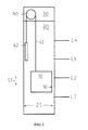
- Fig. 1 shows a vertical cross section of an elevator.
- the elevator comprises a car 10, an elevator shaft 20, a machine room 30, lifting machinery 40, ropes 41, and a counter weight 42.
- the lifting machinery 40 moves the car 10 in a first direction S1 upwards and downwards in the vertically extending elevator shaft 20.
- the walls 21 in the shaft 20 can be formed of an open steel structure or a closed concrete structure.
- the car 10 is carried by the ropes 41, which connect the car 10 to the counter weight 42.
- the car 10 is supported and guided with suitable means when moving upwards and downwards in the elevator shaft 20.
- the car 10 can be stopped at each landing L1 to L4 so that the floor 11 of the car 10 is at the same level as the floor of the landing L1 to L4.
- the car 10 comprises further a door arrangement 50 providing a passage in and out from the car 10 at the landings L1 to L4.
- the invention can naturally be used in any elevator type e.g. in elevators lacking machine room and/or counter weight.
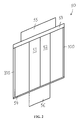
- Fig. 2 shows an axonometric view of a centre opening elevator car door construction with a fixing arrangement for a light curtain.
- the door construction 50 comprises two centre opened door panels 51, 52.
- the upper end of the door panels 51, 52 is supported with rolls on a horizontally extending railing 53.
- the lower end of the door panels 51, 52 is supported with gliding means on a horizontally extending sill profile 54.
- the gliding means extend into a groove in the sill 54.
- the door panels 51, 52 can thus be glided in the horizontal direction along the railing 51 supported by the rolls.
- the movement of the door panels 51, 52 is achieved with an electric motor that is connected with as such known driving machinery to the door panels 51, 52.
- the construction comprises further a support panel 55 above the railing 51 for parts of the driving machinery and a toe guard panel 56 below the sill 54.
- the fixing arrangement 100 for the light curtain extends between the railing 53 and the sill 54.
- the upper end of the fixing arrangement 100 is supported at the railing 53 and the lower end of the fixing arrangement 100 is supported at the sill 54.
- the railing 53 and the sill 54 are attached to the elevator car 10.
- the support panel 55 is attached to the railing 53 and the toe guard panel 56 is attached to the sill 54.
- Fig. 3 shows a horizontal cross section of fig. 2 with the corresponding landing door construction.
- the figure shows the elevator car 10 door construction 50 and the corresponding landing L1 to L4 door construction 60.
- the elevator car 10 door construction 50 is attached to the elevator car 10 and travels thus with the elevator car 10 upwards and downwards in the shaft 20.
- the landing L1 to L4 door construction 60 is attached to the inner surface of the wall 21 in the shaft 20 at each landing L1 to L4.
- the door panels 61, 62 of the landing L1 to L4 will be connected to the door panels 51, 52 of the elevator car 10.
- the door panels 61, 62 of the landing L1 to L4 will thus move in a synchronized way with the door panels 51, 52 of the elevator car 10.
- the door panels 51, 52 of the elevator car 10 and the door panels 61, 62 of the landing L1 to L4 open by moving outwards to the outer edges of the respective door construction 50, 60 and close by moving inwards to the middle of the respective door construction 50, 60.
- the door panels 51, 52, 61, 62 in both door arrangements 50, 60 are centre opened.
- the fixing arrangement 100 for the light curtain is shown at the vertical outer edges of the car 10 door construction 50.
- Fig. 4 shows a horizontal cross section of a side opening elevator car door construction with a fixing arrangement for a light curtain.
- Both door panels 51A, 52A in the elevator car 10 door construction 50A move in the same direction when the door opens and closes.
- the door panels 51A, 52A open so that the first door panel 52A moves first to the left in the figure and when the first door panels 52A is parallel with the second door panel 51 A both door panels 51 A, 52A move further to the left to the leftmost outer edge of the car 10 door construction 50A.
- the door panels 61A, 62A in the landing L1 to L4 door construction 60A move in a corresponding manner as the door panels 51A, 52A in the elevator car 10 door construction 50A.
- the door panels 51A, 52A, 61 A, 62A are side opened in both door constructions 50A, 60A. There are further door frames 63A, 64A at the side edges of the opening to the shaft 20 at the landing L1 to L4.
- the fixing arrangement 100 for the light curtain is shown at the vertical outer edges of the car door construction 50A.
- the fixing arrangement 100 for the light curtain positioned to the left in the figure extends between the railing 53 and the sill 54 so that the upper end of the fixing arrangement 100 is supported at the railing 53 and the lower end of the fixing arrangement 100 is supported at the sill 54.
- the fixing arrangement 100 for the light curtain positioned to the right in the figure is advantageously attached directly to the slam post of the elevator car 10 door construction 50.
- the fixing arrangement 100 for the light curtain positioned to the right in the figure could, however, also extend between the railing 53 and the sill 54 so that the upper end of the fixing arrangement 100 is supported at the railing 53 and the lower end of the fixing arrangement 100 is supported at the sill 54. This would require that the railing 53 and the sill 54 extend beyond the slam post.
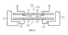
- Fig. 5 shows the door construction in fig. 3 with a different fixing arrangement for a light curtain.
- the elevator car door construction 50 and the landing door construction 60 in fig. 5 correspond to those in fig. 3 .
- the difference is in the position of the fixing arrangement 100 for the light curtain.
- the fixing arrangement 100 is in this embodiment positioned at the outer back edges of the door panels 51, 52.
- the fixing arrangement 100 is thus attached directly to the door panels 51, 52 of the elevator car door arrangement 50. This means that both fixing arrangements 100 will move together with the door panels 51, 52.
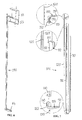
- Fig. 6 shows a perspective view of a first embodiment of a fixing arrangement for a light curtain according to the invention and fig. 7 shows an exploded view of the arrangement in fig. 6 .
- the lower end of the fixing arrangement 100 is attached to the sill 54 and the upper end of the fixing arrangement 100 is attached to the railing 53.
- the fixing arrangement 100 comprises a longitudinal support device 110, 120 comprising a longitudinal first support member 110 and a longitudinal second support member 120.
- the horizontal cross section of the first support member 110 has the form of a laying letter U.
- the horizontal cross section of the second support member 120 is rectangular with a hollow interior i.e. the second support member 120 comprises four walls.
- the upper end portion of the first support member 110 comprises a number of plugs 111 extending outwards from the bottom of the first support member 110.
- the plugs 111 can be welded or riveted to the bottom surface of the first support member 110.
- the lower end portion of the second support member 120 comprises first apertures 121 extending through the second support member 120 i.e. through opposite walls in the second support member 120.
- the cross section of the plugs 111 and the cross section of the first apertures 121 are advantageously circular.
- the plugs 111 of the first support member 110 can thus be pushed into the first apertures 121 of the second support member 120 so that a desired length of the fixing arrangement 100 is achieved.
- the plugs 111 are advantageously provided with external threads whereby nuts can be used on the outer end of the plugs 111 to secure the first support member 110 to the second support member 120.
- the length of the fixing arrangement 100 can be simply altered by altering the apertures 121 in the second support member 120 into which the plugs 111 in the first support member 110 are inserted.
- the fixing arrangement 100 comprises further a first support bracket 130 having the form of a letter L.
- the horizontal branch 131 of the first support bracket 130 can be fastened to the bottom of the sill 54.
- the fastening can be done e.g. by a screw passing through an aperture 133 in the horizontal branch 131 of the first support bracket 130 and a nut.
- a clip 140 e.g. of plastic can be pushed on the vertically upwards extending branch 132 of the first support bracket 130.
- the lower end of the first support member 110 can thus be pushed on the clip 140 in order to secure a safe attachment of the first support member 110 to the first support bracket 130 and thereby to the sill 54.
- the first support bracket 150 can be attached to the sill 54 before the sill 54 is attached to the car 10. The technician can thus simply push the lower end of the first support member 110 on the clip 140 without the need to be able to work below the elevator car 10.
- the fixing arrangement 100 comprises further a second support bracket 150 having the form of a letter L.
- the letter L is turned 90 degrees clockwise around the corner of the letter L so that the vertical branch of the letter L extends vertically downwards.
- the horizontal branch 151 of the second support bracket 150 can be fastened to the upper surface of the railing 53. The fastening can be done e.g. by a screw passing through an aperture 153 in the horizontal branch 151 of the second support bracket 150 and a nut.
- the vertically downwards extending branch 152 of the second support bracket 150 can be attached to the second support member 120.
- the upper end portion of the second support member 120 comprises further second apertures 122. The upper end portion of the second support member 120 can thus be secured to the second support bracket 150 by a bolt passing through a second aperture 122 in the second support bracket 120 and further through an aperture 155 in the fold 154 in the second bracket 150.
- the first support member 110 forms a slot 112 for receiving the light curtain 70.
- the light curtain 70 can thus simply be pushed into the slot 112.
- the light curtain 70 comprises two detectors i.e. a longitudinal transmitter and a longitudinal receiver. The outer dimensions and the form of the two detectors are identical. This means that the first support member 110 can receive the transmitter or the receiver of the light curtain 70.
- Fig. 8 shows a perspective view of a second embodiment of a fixing arrangement for a light curtain according to the invention and fig. 9 shows an exploded view of the arrangement in fig. 8 .
- the fixing arrangement 100 in this embodiment comprises a support device 110 comprising only the first support member 110 with the slot 112 for receiving the light curtain 70. There is thus no second support member 120 in this embodiment.
- the first support member 110 can be attached to the car 10 door front wall slam post 57.
- the first support member 110 can be fastened by glue, by tape or by spot welding to the car door 10 front wall slam post 57.
- This fixing arrangement 100 can be used to attach the first support member 110 directly to the door panels 51, 52 in fig. 5 .
- This fixing arrangement can also be used to attach the first support member 110 directly to the slam post 57 at the right in fig. 4 .
- Fig. 10 shows a variant of the arrangement in fig. 9 .
- the first support member 110 is in this variant integrated into the car 10 door front wall slam post 57.
- This means that the slam post 57 is formed so that the slam post 57 already comprises in itself the first support member 110.
- the first support member 110 is thus not a separate part that is attached to the slam post 57.
- This arrangement could also be applied to the construction in figure 5 .
- the first support members 110 could in figure 5 be integrated into the door panels 51, 61 instead of using separate first support members 110 that are attached to the door panels 51, 52.
- the door constructions in the figures comprise two door panels 51, 52, 51A, 52A.
- the door construction could, however, comprise any number of door panels. There could be only one door panel or there could be more than two door panels e.g. four door panels in the door construction.
- the door constructions in the figures only show sliding door panels 51, 52, 51A, 52A.
- the inventive fixing arrangement 100 for the light curtain could, however, also be used in door constructions where the door panels are supported by hinges.
- the figures show two embodiments of the fixing arrangement 100 for the light curtain 70.
- the support device 110, 120 comprises in the first embodiment shown in figures 6 and 7 the first support member 110 and the second support member 120 attached to each other as well as the first support bracket 130 and the second support bracket 150.
- the support device 110 comprises in the second embodiment shown in figures 8 and 9 only the first support member 110.
- the first support member 110 is in figures 8 and 9 a separate entity, but an integral part of the door construction in the variant shown in fig. 10 .
- the first embodiment of the fixing arrangement 100 can be attached to a stationary part of the door construction 50, 50A i.e. to the railing 53 and the sill 54.
- the second embodiment of the fixing arrangement 100 can be attached to a stationary part of the door construction 50, 50A i.e. to the car 10 door front wall slam post 57 or to a moving part of the door construction 50, 50A i.e. the door panels 51, 52.
- the second support bracket 150 in figures 6 and 7 could be modified so that the vertical branch 152 comprises a round tube.
- the tube can slide into the upper end of the second support member 120.
- the diameter of the round tube is such that it fits tightly into the rectangular cross section of the second support member 120.
- the horizontal branch 151 of the second support bracket 150 can correspond to that shown in figures 6 and 7 i.e. it could comprise a flat bar with on aperture 153.
- the size and the dimensions of the first support member 110 could naturally be adapted according to the size and dimensions of the transmitter and the receiver.
- the first support member 110 will accommodate to small variations in the thickness of the transmitter and the receiver. Major changes in the thickness of the transmitter and the receiver will, however, require change of the first support member 110.
- the parts in the fixing arrangement 100 are advantageously made of metal or of metal alloy.
- the material thickness is chosen so that the light curtain is pressed with a sufficient pressure within the first support member 110.
Landscapes
- Elevator Door Apparatuses (AREA)
Abstract

Description
- The invention relates to a fixing arrangement for a light curtain in an elevator according to the preamble of claim 1.
- The elevator comprises an elevator car with a door construction comprising at least one door panel opening and closing a passage to the elevator car. The light curtain to be fastened with the fixing arrangement comprises a longitudinal transmitter and a longitudinal receiver facing towards each other.
- A light curtain in an elevator comprises two opposite vertical detectors at a horizontal distance from each other. One detector comprises a transmitter and the other detector comprises a receiver. The transmitter comprises a number of light emitting diodes emitting infrared light which is directed with a lens system towards the opposite receiver. When an object enters the region between the transmitter and the receiver some of the infrared beams sent by the transmitter will be obscured. The receiver will detect that some infrared beams are missing and this will activate a safety function which will prevent the closing of the door panels. The light curtain functions thus as a safety device preventing people and goods from being pressed between the door panels when the door panels are to be closed. The door panels will close automatically when a certain time has passed after they have opened unless the light curtain prevents closing of the door panels.
- A sliding door construction in an elevator comprises a horizontal railing, a horizontal sill and at least one door panel. The upper end of the at least one door panel is supported with rolls at the railing and the lower end of the at least one door panel is supported with gliding means at the sill. There are centre opening door constructions and side opening door constructions. In a centre opening door construction the door panels on both sides of the centre of the door construction move in opposite directions. In a side door construction the door panels move in the same direction.
- In a centre opening door construction, the first detector (transmitter or receiver) and the second detector (receiver of transmitter) are positioned at opposite outer ends of the railing and the sill so that the first detector and the second detector face towards each other. The fixing arrangement in prior art solutions comprises an L-shaped vertically extending support profile. The upper end of the support profile is attached with a bracket and a screw to the railing and the lower end of the support profile is attached in a corresponding way with a bracket and a screw to the sill. The first detector and the second detector are attached to the plane surface of the respective support profile with screws.
- The vertically between the railing and the sill extending support profile becomes rather long. The support profile is thus problematic to pack together with the other equipment in the door construction. When the vertical support profile is made of one piece it suits only one door height. Vertical support profiles of different length must thus be kept in stock to suit different door heights. There are also solutions where the vertical support profile is made of two separate pieces. The two separate pieces are then attached to each other with pop-rivets at the installation site. This will cause a longer installation time and a risk of installation mistakes.
- Holes are needed in the transmitter and the receiver in order for the screws to pass through the transmitter and the receiver when the transmitter and the receiver are attached to the vertical support profile. These holes in the transmitter and the receiver will decrease the IP-class of the light curtain.
- In a side opening door construction, the first detector (transmitter or receiver) can be attached in the same way as in a centre opening door construction to the end of the railing and to the end of the sill at that end of the door construction towards which the door panel opens. The fixing of the second detector (receiver or transmitter) is in a prior art solution done to the slam post against which the door panel closes. The second detector is attached from the upper end and the lower end with a screw and a clamp to the slam post.
- The light curtain has also been attached to the door panels in prior art solutions. The detector is in some prior art solutions positioned between an inner profile and a fixing plate. The whole package is then fastened with screws passing through the package to the inner surface of the door panel. The transmitter and the receiver is positioned against each other at the inner surface of the door panels at the opposite edges of the door panels in a centre opening door construction. In a side opening door construction the second detector would have to be fastened to the slam post against which the door panel closes. The second detector could be pre-installed at the door factory to the slam post so that the detector is flush mounted with the surface of the slam post. The edge of the door panel would thus close against the detector. The other possibility is to install the detector to the inner surface of the slam post, said inner surface being parallel with the door panel.
- Prior art solutions in which the light curtain is attached to the door panels involve a risk that screw-heads cause scratches to the door panels. Prior art solutions require holes in the transmitter and the receiver in order for the fastening screws to pass through the transmitter and the receiver. These holes in the transmitter and the receiver will decrease the IP-class of the light curtain. Maintenance and replacement of a light curtain fastened with screws and/or brackets and/or clamps means that the screws and/or the brackets and/or the clamps have to be disassembled in order to be able to maintenance or replace the light curtain.
- An object of the present invention is to provide an improved fixing arrangement for a light curtain in an elevator.
- The fixing arrangement for the light curtain in an elevator according to the invention is characterized by what is stated in the characterizing portion of claim 1.
- The fixing arrangement is characterized in that it comprises at least one longitudinal support device comprising a longitudinal first support member having a cross section in the form of a letter U, whereby the letter U forms a slot for receiving the transmitter or the receiver of the light curtain.
- The fixing arrangement according to the invention is easy and fast to install. The transmitter and the receiver of the light curtain can simply by pushed into the slot in the first support member. The transmitter and the receiver of the light curtain are then shape locked in the slot in the first support member. The transmitter and the receiver of the light curtain can further be pulled from the slot in the first support member when the transmitter and the receiver of the light curtain are to be maintained or replaced. No tools are needed in order to push the transmitter and the receiver of the light curtain into the slot or to pull the transmitter and the receiver of the light curtain from the slot in the first support member. Maintenance of the light curtain is thus fast and easy.
- The fixing arrangement can be installed in advance to the door construction e.g. during the elevator installation. The transmitter and the receiver of the light curtain can then be pushed in place into the slot in the first support member at a later stage when the elevator will be handed over to normal use. The transmitter and the receiver of the light curtain will thus not be subjected to damage and dust during the elevator installation.
- The fixing arrangement according to the invention provides a reliable and long lasting attachment for the light curtain. There will be less problems relating to the attachment of the light curtain during the lifetime of the light curtain compared to prior art solutions.
- The fixing arrangement according to the invention can be used to attach the light curtain to a stationary part or to a mobile part of the elevator car door construction. The fixing arrangement could be attached to the railing and the sill or to the slam post of the door panels, which are stationary parts of the door construction. The fixing arrangement could on the other hand be attached to the door panels, which are mobile parts of the door construction.
- The invention will in the following be described in greater detail by means of preferred embodiments with reference to the attached drawings, in which
-
Fig. 1 shows a vertical cross section of an elevator. -
Fig. 2 shows an axonometric view of a centre opening elevator car door construction with a fixing arrangement for a light curtain. -
Fig. 3 shows a horizontal cross section offig. 2 with the corresponding landing door construction. -
Fig. 4 shows a horizontal cross section of a side opening elevator car door construction with a fixing arrangement for a light curtain. -
Fig. 5 shows the door construction infig. 3 with a different fixing arrangement for a light curtain. -
Fig. 6 shows a perspective view of a first embodiment of a fixing arrangement for a light curtain according to the invention. -
Fig. 7 shows an exploded view of the arrangement infig. 6 . -
Fig. 8 shows a perspective view of a second embodiment of a fixing arrangement for a light curtain according to the invention. -
Fig. 9 shows an exploded view of the arrangement infig. 8 . -
Fig. 10 shows a variant of the arrangement infig. 9 . -
Fig. 1 shows a vertical cross section of an elevator. The elevator comprises acar 10, anelevator shaft 20, amachine room 30, liftingmachinery 40,ropes 41, and acounter weight 42. Thelifting machinery 40 moves thecar 10 in a first direction S1 upwards and downwards in the vertically extendingelevator shaft 20. Thewalls 21 in theshaft 20 can be formed of an open steel structure or a closed concrete structure. Thecar 10 is carried by theropes 41, which connect thecar 10 to thecounter weight 42. Thecar 10 is supported and guided with suitable means when moving upwards and downwards in theelevator shaft 20. Thecar 10 can be stopped at each landing L1 to L4 so that the floor 11 of thecar 10 is at the same level as the floor of the landing L1 to L4. Thecar 10 comprises further adoor arrangement 50 providing a passage in and out from thecar 10 at the landings L1 to L4. The invention can naturally be used in any elevator type e.g. in elevators lacking machine room and/or counter weight. -
Fig. 2 shows an axonometric view of a centre opening elevator car door construction with a fixing arrangement for a light curtain. Thedoor construction 50 comprises two centre openeddoor panels door panels railing 53. The lower end of thedoor panels sill profile 54. The gliding means extend into a groove in thesill 54. Thedoor panels railing 51 supported by the rolls. The movement of thedoor panels door panels support panel 55 above therailing 51 for parts of the driving machinery and atoe guard panel 56 below thesill 54. There is further a fixingarrangement 100 for the light curtain at each vertical outer edge of thedoor construction 50. The fixingarrangement 100 for the light curtain extends between therailing 53 and thesill 54. The upper end of the fixingarrangement 100 is supported at therailing 53 and the lower end of the fixingarrangement 100 is supported at thesill 54. Therailing 53 and thesill 54 are attached to theelevator car 10. Thesupport panel 55 is attached to therailing 53 and thetoe guard panel 56 is attached to thesill 54. This means that thedoor panels door construction 50. Thedoor panels door construction 50. -
Fig. 3 shows a horizontal cross section offig. 2 with the corresponding landing door construction. The figure shows theelevator car 10door construction 50 and the corresponding landing L1 toL4 door construction 60. Theelevator car 10door construction 50 is attached to theelevator car 10 and travels thus with theelevator car 10 upwards and downwards in theshaft 20. The landing L1 toL4 door construction 60 is attached to the inner surface of thewall 21 in theshaft 20 at each landing L1 to L4. When theelevator car 10 stops at a landing L1 to L4 thedoor panels door panels elevator car 10. Thedoor panels door panels elevator car 10. Thedoor panels elevator car 10 and thedoor panels respective door construction respective door construction door panels door arrangements further door frames shaft 20 at the landing L1 to L4. The fixingarrangement 100 for the light curtain is shown at the vertical outer edges of thecar 10door construction 50. -
Fig. 4 shows a horizontal cross section of a side opening elevator car door construction with a fixing arrangement for a light curtain. Bothdoor panels elevator car 10door construction 50A move in the same direction when the door opens and closes. Thedoor panels first door panel 52A moves first to the left in the figure and when thefirst door panels 52A is parallel with thesecond door panel 51 A bothdoor panels car 10door construction 50A. Thedoor panels L4 door construction 60A move in a corresponding manner as thedoor panels elevator car 10door construction 50A. Thedoor panels door constructions further door frames shaft 20 at the landing L1 to L4. The fixingarrangement 100 for the light curtain is shown at the vertical outer edges of thecar door construction 50A. The fixingarrangement 100 for the light curtain positioned to the left in the figure extends between therailing 53 and thesill 54 so that the upper end of the fixingarrangement 100 is supported at therailing 53 and the lower end of the fixingarrangement 100 is supported at thesill 54. The fixingarrangement 100 for the light curtain positioned to the right in the figure is advantageously attached directly to the slam post of theelevator car 10door construction 50. The fixingarrangement 100 for the light curtain positioned to the right in the figure could, however, also extend between therailing 53 and thesill 54 so that the upper end of the fixingarrangement 100 is supported at therailing 53 and the lower end of the fixingarrangement 100 is supported at thesill 54. This would require that therailing 53 and thesill 54 extend beyond the slam post. -
Fig. 5 shows the door construction infig. 3 with a different fixing arrangement for a light curtain. The elevatorcar door construction 50 and thelanding door construction 60 infig. 5 correspond to those infig. 3 . There are two centre openeddoor panels arrangement 100 for the light curtain. The fixingarrangement 100 is in this embodiment positioned at the outer back edges of thedoor panels arrangement 100 is thus attached directly to thedoor panels car door arrangement 50. This means that both fixingarrangements 100 will move together with thedoor panels -
Fig. 6 shows a perspective view of a first embodiment of a fixing arrangement for a light curtain according to the invention andfig. 7 shows an exploded view of the arrangement infig. 6 . The lower end of the fixingarrangement 100 is attached to thesill 54 and the upper end of the fixingarrangement 100 is attached to therailing 53. The fixingarrangement 100 comprises alongitudinal support device first support member 110 and a longitudinalsecond support member 120. The horizontal cross section of thefirst support member 110 has the form of a laying letter U. The horizontal cross section of thesecond support member 120 is rectangular with a hollow interior i.e. thesecond support member 120 comprises four walls. The upper end portion of thefirst support member 110 comprises a number ofplugs 111 extending outwards from the bottom of thefirst support member 110. Theplugs 111 can be welded or riveted to the bottom surface of thefirst support member 110. The lower end portion of thesecond support member 120 comprisesfirst apertures 121 extending through thesecond support member 120 i.e. through opposite walls in thesecond support member 120. The cross section of theplugs 111 and the cross section of thefirst apertures 121 are advantageously circular. Theplugs 111 of thefirst support member 110 can thus be pushed into thefirst apertures 121 of thesecond support member 120 so that a desired length of the fixingarrangement 100 is achieved. Theplugs 111 are advantageously provided with external threads whereby nuts can be used on the outer end of theplugs 111 to secure thefirst support member 110 to thesecond support member 120. - The length of the fixing
arrangement 100 can be simply altered by altering theapertures 121 in thesecond support member 120 into which theplugs 111 in thefirst support member 110 are inserted. - The fixing
arrangement 100 comprises further afirst support bracket 130 having the form of a letter L. Thehorizontal branch 131 of thefirst support bracket 130 can be fastened to the bottom of thesill 54. The fastening can be done e.g. by a screw passing through anaperture 133 in thehorizontal branch 131 of thefirst support bracket 130 and a nut. Aclip 140 e.g. of plastic can be pushed on the vertically upwards extendingbranch 132 of thefirst support bracket 130. The lower end of thefirst support member 110 can thus be pushed on theclip 140 in order to secure a safe attachment of thefirst support member 110 to thefirst support bracket 130 and thereby to thesill 54. The first support bracket 150 can be attached to thesill 54 before thesill 54 is attached to thecar 10. The technician can thus simply push the lower end of thefirst support member 110 on theclip 140 without the need to be able to work below theelevator car 10. - The fixing
arrangement 100 comprises further a second support bracket 150 having the form of a letter L. The letter L is turned 90 degrees clockwise around the corner of the letter L so that the vertical branch of the letter L extends vertically downwards. Thehorizontal branch 151 of the second support bracket 150 can be fastened to the upper surface of therailing 53. The fastening can be done e.g. by a screw passing through anaperture 153 in thehorizontal branch 151 of the second support bracket 150 and a nut. The vertically downwards extendingbranch 152 of the second support bracket 150 can be attached to thesecond support member 120. There is afold 154 in the vertically downwards extendingbranch 152 of the second support member 150. The upper end portion of thesecond support member 120 comprises further second apertures 122. The upper end portion of thesecond support member 120 can thus be secured to the second support bracket 150 by a bolt passing through a second aperture 122 in thesecond support bracket 120 and further through anaperture 155 in thefold 154 in the second bracket 150. - The
first support member 110 forms aslot 112 for receiving the light curtain 70. The light curtain 70 can thus simply be pushed into theslot 112. The light curtain 70 comprises two detectors i.e. a longitudinal transmitter and a longitudinal receiver. The outer dimensions and the form of the two detectors are identical. This means that thefirst support member 110 can receive the transmitter or the receiver of the light curtain 70. -
Fig. 8 shows a perspective view of a second embodiment of a fixing arrangement for a light curtain according to the invention andfig. 9 shows an exploded view of the arrangement infig. 8 . The fixingarrangement 100 in this embodiment comprises asupport device 110 comprising only thefirst support member 110 with theslot 112 for receiving the light curtain 70. There is thus nosecond support member 120 in this embodiment. Thefirst support member 110 can be attached to thecar 10 door frontwall slam post 57. Thefirst support member 110 can be fastened by glue, by tape or by spot welding to thecar door 10 frontwall slam post 57. This fixingarrangement 100 can be used to attach thefirst support member 110 directly to thedoor panels fig. 5 . This fixing arrangement can also be used to attach thefirst support member 110 directly to theslam post 57 at the right infig. 4 . -
Fig. 10 shows a variant of the arrangement infig. 9 . Thefirst support member 110 is in this variant integrated into thecar 10 door frontwall slam post 57. This means that theslam post 57 is formed so that theslam post 57 already comprises in itself thefirst support member 110. Thefirst support member 110 is thus not a separate part that is attached to theslam post 57. This arrangement could also be applied to the construction infigure 5 . Thefirst support members 110 could infigure 5 be integrated into thedoor panels first support members 110 that are attached to thedoor panels - The door constructions in the figures comprise two
door panels - The door constructions in the figures only show sliding
door panels inventive fixing arrangement 100 for the light curtain could, however, also be used in door constructions where the door panels are supported by hinges. - The figures show two embodiments of the fixing
arrangement 100 for the light curtain 70. Thesupport device figures 6 and 7 thefirst support member 110 and thesecond support member 120 attached to each other as well as thefirst support bracket 130 and the second support bracket 150. Thesupport device 110 comprises in the second embodiment shown infigures 8 and 9 only thefirst support member 110. Thefirst support member 110 is infigures 8 and 9 a separate entity, but an integral part of the door construction in the variant shown infig. 10 . The first embodiment of the fixingarrangement 100 can be attached to a stationary part of thedoor construction railing 53 and thesill 54. The second embodiment of the fixingarrangement 100 can be attached to a stationary part of thedoor construction car 10 door frontwall slam post 57 or to a moving part of thedoor construction door panels - The second support bracket 150 in
figures 6 and 7 could be modified so that thevertical branch 152 comprises a round tube. The tube can slide into the upper end of thesecond support member 120. The diameter of the round tube is such that it fits tightly into the rectangular cross section of thesecond support member 120. Thehorizontal branch 151 of the second support bracket 150 can correspond to that shown infigures 6 and 7 i.e. it could comprise a flat bar with onaperture 153. - The size and the dimensions of the
first support member 110 could naturally be adapted according to the size and dimensions of the transmitter and the receiver. Thefirst support member 110 will accommodate to small variations in the thickness of the transmitter and the receiver. Major changes in the thickness of the transmitter and the receiver will, however, require change of thefirst support member 110. - The parts in the fixing
arrangement 100 are advantageously made of metal or of metal alloy. The material thickness is chosen so that the light curtain is pressed with a sufficient pressure within thefirst support member 110. - It will be obvious to a person skilled in the art that, as the technology advances, the inventive concept can be implemented in various ways. The invention and its embodiments are not limited to the examples described above but may vary within the scope of the claims.
Claims (13)
- Fixing arrangement (100) for a light curtain (70) in an elevator, said elevator comprising an elevator car (10) with a door construction (50, 50A) comprising at least one door panel (51, 52, 51A, 52A) opening and closing a passage to the elevator car (10), said light curtain (70) comprising a longitudinal transmitter and a longitudinal receiver facing towards each other, characterized in that the fixing arrangement (100) comprises at least one longitudinal support device (110, 120) comprising a longitudinal first support member (110) having a cross section in the form of a letter U, whereby the letter U forms a slot (112) for receiving the transmitter or the receiver of the light curtain (70).
- Fixing arrangement according to claim 1, characterized in that the at least one door panel (51, 52, 51A, 52A) is a sliding door panel (51, 52, 51 A, 52A), whereby an upper end of the at least one door panel (51, 52, 51 A, 52A) is supported on a horizontally extending railing (53) and a lower end of the at least one door panel (51, 52, 51A, 52A) is supported on a horizontally extending sill (54).
- Fixing arrangement according to claim 2, characterized in that the door construction (50) comprises at least two centre opening sliding door panels (51, 52).
- Fixing arrangement according to claim 3, characterized in that the fixing arrangement (100) comprises two longitudinal support devices (110, 120) positioned at the vertical outer edges of the door construction (50) so that the slots (112) of the two longitudinal support devices (110, 120) and thereby also the transmitter and the receiver of the light curtain (70) face towards each other, whereby an upper end of each of the two longitudinal support devices (110, 120) is supported at the railing (53) and an lower end of each of the two longitudinal support devices (110, 120) is supported at the sill (54).
- Fixing arrangement according to claim 4, characterized in that each of the two longitudinal support devices (110, 120) comprises a longitudinal first support member (110) and a longitudinal second support member (120) being attached to each other, whereby a lower end of each of the two longitudinal first support members (110) is attached with a first support bracket (130) to the sill (54) and an upper end of each of the two longitudinal second support members (120) is attached with a second support bracket (150) to the railing (53).
- Fixing arrangement according to claim 5, characterized in that the first support bracket (130) has the form of a letter L, whereby a horizontal branch (131) of the first support bracket is attached to the sill (54) and the lower end of the longitudinal first support member (110) is attached to a vertical branch (132) of the first support bracket (130), and the second support bracket (150) has the form of a letter L turned 90 degrees clockwise, whereby a horizontal branch (151) of the second support bracket (150) is attached to the railing (53) and an upper end of the longitudinal second support member (120) is attached to the vertical branch (152) of the second support bracket (150).
- Fixing arrangement according to claim 5 or 6, characterized in that an upper end portion of each of the two longitudinal first support members (110) comprises plugs (111) extending outwards from a bottom of the first support member (110) and a lower end portion of each of the two longitudinal second support members (120) comprises first apertures (121) passing through the longitudinal second support member (120), whereby the first apertures (121) receive the plugs (111) establishing attachment between the longitudinal first support member (110) and the longitudinal second support member (120).
- Fixing arrangement according to claim 2, characterized in that the door construction (50A) comprises at least one side opening sliding door panel (51 A, 52A).
- Fixing arrangement according to claim 8, characterized in that the fixing arrangement (100) comprises two longitudinal support devices (110, 120) positioned at the vertical outer edges of the door construction (50A) so that the slots (112) of the two longitudinal support devices (110, 120) and thereby also the transmitter and the receiver of the light curtain (70) face towards each other, whereby a first one of the two longitudinal support devices (110, 120) is attached to the slam post (57) towards which the at least one door panel (51A, 52A) closes and a second one of the two support devices (110, 120) is supported from the upper end at the railing (53) and from the lower end at the sill (54).
- Fixing arrangement according to claim 9, characterized in that the first one of the two support devices (110, 120) comprises only a longitudinal first support member (110) and the second one of the two support devices (110, 120) comprises a longitudinal first support member (110) and a longitudinal second support member (120) being attached to each other, whereby the first one of the two support devices (110, 120) is attached directly to the slam post (57) towards which the at least one door panel (51 A, 51 A) closes and the second one of the two support devices (110, 120) is attached with a first support bracket (130) from a lower end of the longitudinal first support member (110) of the longitudinal second support device (110, 120) to the sill (54) and with a second support bracket (150) from an upper end of the longitudinal second support member (120) of the longitudinal second support device (110, 120) to the railing (53).
- Fixing arrangement according to claim 10, characterized in that the first support bracket (130) has the form of a letter L, whereby a horizontal branch (131) of the first support bracket is attached to the sill (54) and the lower end of the longitudinal first support member (110) of the longitudinal second support device (110, 120) is attached to a vertical branch (132) of the first support bracket (130), and the second support bracket (150) has the form of a letter L turned 90 degrees clockwise, whereby a horizontal branch (151) of the second support bracket (150) is attached to the railing (53) and an upper end of the longitudinal second support member (120) of the longitudinal second support device (110, 120) is attached to the vertical branch (152) of the second support bracket (150).
- Fixing arrangement according to claim 10 or 11, characterized in that an upper end portion of the longitudinal first support member (110) of the longitudinal second support device (110, 120) comprises plugs (111) extending outwards from a bottom of the longitudinal first support member (110) of the longitudinal second support device (110, 120) and a lower end portion of the longitudinal second support member (120) of the longitudinal second support device (110, 120) comprises first apertures (121) passing through the longitudinal second support member (120) of the longitudinal second support device (1110, 120), whereby the first apertures (121) receive the plugs (111) establishing attachment between the longitudinal first support member (110) of the longitudinal second support device (110, 120) and the longitudinal second support member (120) of the longitudinal second support device (110, 120).
- Fixing arrangement according to claim 3, characterized in that the fixing arrangement (100) comprises two longitudinal support devices (110, 120) positioned so that the slots (112) of the two longitudinal support devices (110, 120) and thereby also the transmitter and the receiver of the light curtain (70) face towards each other, each longitudinal support device (110, 120) comprising only a longitudinal first support member (110), whereby a first one of the two longitudinal first support members (110) is attached directly to a first door panel (51) and the second one of the two longitudinal first support members (110) is attached directly to a second door panel (52).
Priority Applications (4)
| Application Number | Priority Date | Filing Date | Title |
|---|---|---|---|
| EP13163453.7A EP2789564B1 (en) | 2013-04-12 | 2013-04-12 | Fixing arrangement for a light curtain in an elevator |
| US14/227,251 US9624072B2 (en) | 2013-04-12 | 2014-03-27 | Elevator having a light curtain fixing arrangement |
| CN201410146052.XA CN104098012B (en) | 2013-04-12 | 2014-04-11 | Fixation device for the light curtain in elevator |
| HK15101736.0A HK1201249B (en) | 2013-04-12 | 2015-02-16 | Fixing arrangement for a light curtain in an elevator |
Applications Claiming Priority (1)
| Application Number | Priority Date | Filing Date | Title |
|---|---|---|---|
| EP13163453.7A EP2789564B1 (en) | 2013-04-12 | 2013-04-12 | Fixing arrangement for a light curtain in an elevator |
Publications (2)
| Publication Number | Publication Date |
|---|---|
| EP2789564A1 true EP2789564A1 (en) | 2014-10-15 |
| EP2789564B1 EP2789564B1 (en) | 2020-09-16 |
Family
ID=48143452
Family Applications (1)
| Application Number | Title | Priority Date | Filing Date |
|---|---|---|---|
| EP13163453.7A Active EP2789564B1 (en) | 2013-04-12 | 2013-04-12 | Fixing arrangement for a light curtain in an elevator |
Country Status (3)
| Country | Link |
|---|---|
| US (1) | US9624072B2 (en) |
| EP (1) | EP2789564B1 (en) |
| CN (1) | CN104098012B (en) |
Cited By (1)
| Publication number | Priority date | Publication date | Assignee | Title |
|---|---|---|---|---|
| CN109502440A (en) * | 2018-12-06 | 2019-03-22 | 苏州德里克智能技术有限公司 | A kind of elevator light curtain detection device |
Families Citing this family (3)
| Publication number | Priority date | Publication date | Assignee | Title |
|---|---|---|---|---|
| CN106629281A (en) * | 2015-10-30 | 2017-05-10 | 天津优安达电梯制造有限公司 | Integrated type control handwheel locking device |
| CN113165845B (en) * | 2019-01-17 | 2023-12-26 | 三菱电机楼宇解决方案株式会社 | Supporting device and supporting method for elevator safety device |
| CN116281528A (en) * | 2023-03-29 | 2023-06-23 | 伟龙意程智能科技(江苏)有限公司 | Elevator light curtain mounting structure capable of achieving efficient self-checking |
Citations (4)
| Publication number | Priority date | Publication date | Assignee | Title |
|---|---|---|---|---|
| US4976337A (en) * | 1987-06-11 | 1990-12-11 | Formula Systems Limited | Proximity detection systems |
| EP0699619A2 (en) * | 1994-08-04 | 1996-03-06 | Memco Limited | Lift installation for preventing premature closure of the sliding doors |
| JP2002145566A (en) * | 2000-11-10 | 2002-05-22 | Hitachi Building Systems Co Ltd | Elevator doorway safety devices |
| US7755024B2 (en) * | 2004-11-15 | 2010-07-13 | Memco Limited | Safety sensing system for a powered door system |
Family Cites Families (15)
| Publication number | Priority date | Publication date | Assignee | Title |
|---|---|---|---|---|
| US3370677A (en) * | 1966-01-12 | 1968-02-27 | Westinghouse Electric Corp | Proximity sensing apparatus and sensor therefor |
| US3834081A (en) * | 1973-03-30 | 1974-09-10 | Gyro Tech Inc | Automatic sliding door system |
| US5394961A (en) * | 1993-04-29 | 1995-03-07 | Montgomery Elevator Company | Safety edge assembly for elevator doorways |
| JPH08225279A (en) * | 1995-02-23 | 1996-09-03 | Otis Elevator Co | Door safety device of elevator |
| US5712458A (en) * | 1995-08-09 | 1998-01-27 | The Peelle Company | Door sensor beam |
| JP3861373B2 (en) | 1997-05-09 | 2006-12-20 | 三菱電機株式会社 | Elevator doorway safety device |
| JP2000118928A (en) | 1998-10-15 | 2000-04-25 | Hitachi Building Systems Co Ltd | Elevator doorway safety devices |
| JP2003089489A (en) | 2001-09-19 | 2003-03-25 | Hitachi Building Systems Co Ltd | Elevator entrance safety devices |
| JP4208535B2 (en) * | 2001-12-12 | 2009-01-14 | 株式会社キーエンス | Multi-optical axis photoelectric sensor and its fixture |
| US6710325B2 (en) * | 2001-12-20 | 2004-03-23 | Dynapar Corporation | Light curtain mounting system wherein housing and mounting bracket include curved surfaces |
| GB2400905A (en) * | 2003-04-24 | 2004-10-27 | Memco Ltd | Edge device for a powered door with infra-red and visible elements |
| DE102004046725B4 (en) * | 2004-09-25 | 2007-08-09 | Sick Ag | Housing for a light grid |
| US8646206B2 (en) * | 2012-01-23 | 2014-02-11 | Door Control Services, Inc. | System for presence detection in a door assembly |
| JP6084522B2 (en) * | 2013-06-21 | 2017-02-22 | 株式会社キーエンス | Multi-axis photoelectric sensor |
| GB2526072B (en) * | 2014-05-02 | 2019-08-14 | Ensota Ltd | A method of operating an automatic door installation |
-
2013
- 2013-04-12 EP EP13163453.7A patent/EP2789564B1/en active Active
-
2014
- 2014-03-27 US US14/227,251 patent/US9624072B2/en active Active
- 2014-04-11 CN CN201410146052.XA patent/CN104098012B/en active Active
Patent Citations (4)
| Publication number | Priority date | Publication date | Assignee | Title |
|---|---|---|---|---|
| US4976337A (en) * | 1987-06-11 | 1990-12-11 | Formula Systems Limited | Proximity detection systems |
| EP0699619A2 (en) * | 1994-08-04 | 1996-03-06 | Memco Limited | Lift installation for preventing premature closure of the sliding doors |
| JP2002145566A (en) * | 2000-11-10 | 2002-05-22 | Hitachi Building Systems Co Ltd | Elevator doorway safety devices |
| US7755024B2 (en) * | 2004-11-15 | 2010-07-13 | Memco Limited | Safety sensing system for a powered door system |
Cited By (1)
| Publication number | Priority date | Publication date | Assignee | Title |
|---|---|---|---|---|
| CN109502440A (en) * | 2018-12-06 | 2019-03-22 | 苏州德里克智能技术有限公司 | A kind of elevator light curtain detection device |
Also Published As
| Publication number | Publication date |
|---|---|
| HK1201249A1 (en) | 2015-08-28 |
| CN104098012A (en) | 2014-10-15 |
| US9624072B2 (en) | 2017-04-18 |
| US20140305746A1 (en) | 2014-10-16 |
| EP2789564B1 (en) | 2020-09-16 |
| CN104098012B (en) | 2019-01-22 |
Similar Documents
| Publication | Publication Date | Title |
|---|---|---|
| US20150246792A1 (en) | Elevator car with a maintenance window | |
| US9624072B2 (en) | Elevator having a light curtain fixing arrangement | |
| US11498812B2 (en) | Elevator landing door assembly and its installation method | |
| CN108883904A (en) | Lift car, elevator device and the method for safeguarding elevator device | |
| EP2774887A1 (en) | Door sill unit and method for an elevator landing door unit | |
| KR20100101411A (en) | Device for preventing a front door of elevator from detachment | |
| KR101410539B1 (en) | Elevator car compartment and elevator car | |
| US20200307654A1 (en) | Window arrangement for a rail vehicle | |
| KR101774542B1 (en) | Sliding door unit | |
| EP2406164B1 (en) | Elevator system with guide rail bracket | |
| US11060334B2 (en) | Vertical sliding element | |
| EP2746209A1 (en) | Mounting of guides for guide rails on an elevator car. | |
| KR101960735B1 (en) | Safety apparatus for over head door | |
| EP3418240B1 (en) | An elevator car wall | |
| KR101307214B1 (en) | Guard device for entrance and exit of working lift | |
| HK1201249B (en) | Fixing arrangement for a light curtain in an elevator | |
| US20160236908A1 (en) | Elevator door arrangement | |
| JP6673816B2 (en) | Mounting method of elevator device and door open / close detection switch | |
| JP2010184755A (en) | Landing hall unit of elevator | |
| CN211310512U (en) | Adjustable mounting bracket for sensor module | |
| JP6293307B2 (en) | elevator | |
| JP2018141358A (en) | Entrance fittings | |
| JP6412712B2 (en) | Entrance fittings | |
| KR200436145Y1 (en) | Positioning structure of guide roller for overhead door | |
| WO2018052440A1 (en) | Elevator door closing device |
Legal Events
| Date | Code | Title | Description |
|---|---|---|---|
| PUAI | Public reference made under article 153(3) epc to a published international application that has entered the european phase |
Free format text: ORIGINAL CODE: 0009012 |
|
| 17P | Request for examination filed |
Effective date: 20130412 |
|
| AK | Designated contracting states |
Kind code of ref document: A1 Designated state(s): AL AT BE BG CH CY CZ DE DK EE ES FI FR GB GR HR HU IE IS IT LI LT LU LV MC MK MT NL NO PL PT RO RS SE SI SK SM TR |
|
| AX | Request for extension of the european patent |
Extension state: BA ME |
|
| RAP1 | Party data changed (applicant data changed or rights of an application transferred) |
Owner name: KONE CORPORATION |
|
| RIN1 | Information on inventor provided before grant (corrected) |
Inventor name: KUISMA, PETRI, |
|
| R17P | Request for examination filed (corrected) |
Effective date: 20150319 |
|
| RBV | Designated contracting states (corrected) |
Designated state(s): AL AT BE BG CH CY CZ DE DK EE ES FI FR GB GR HR HU IE IS IT LI LT LU LV MC MK MT NL NO PL PT RO RS SE SI SK SM TR |
|
| GRAP | Despatch of communication of intention to grant a patent |
Free format text: ORIGINAL CODE: EPIDOSNIGR1 |
|
| STAA | Information on the status of an ep patent application or granted ep patent |
Free format text: STATUS: GRANT OF PATENT IS INTENDED |
|
| INTG | Intention to grant announced |
Effective date: 20200504 |
|
| GRAS | Grant fee paid |
Free format text: ORIGINAL CODE: EPIDOSNIGR3 |
|
| GRAA | (expected) grant |
Free format text: ORIGINAL CODE: 0009210 |
|
| STAA | Information on the status of an ep patent application or granted ep patent |
Free format text: STATUS: THE PATENT HAS BEEN GRANTED |
|
| AK | Designated contracting states |
Kind code of ref document: B1 Designated state(s): AL AT BE BG CH CY CZ DE DK EE ES FI FR GB GR HR HU IE IS IT LI LT LU LV MC MK MT NL NO PL PT RO RS SE SI SK SM TR |
|
| REG | Reference to a national code |
Ref country code: GB Ref legal event code: FG4D |
|
| REG | Reference to a national code |
Ref country code: CH Ref legal event code: EP |
|
| REG | Reference to a national code |
Ref country code: DE Ref legal event code: R096 Ref document number: 602013072530 Country of ref document: DE |
|
| REG | Reference to a national code |
Ref country code: IE Ref legal event code: FG4D |
|
| REG | Reference to a national code |
Ref country code: AT Ref legal event code: REF Ref document number: 1314016 Country of ref document: AT Kind code of ref document: T Effective date: 20201015 |
|
| PG25 | Lapsed in a contracting state [announced via postgrant information from national office to epo] |
Ref country code: HR Free format text: LAPSE BECAUSE OF FAILURE TO SUBMIT A TRANSLATION OF THE DESCRIPTION OR TO PAY THE FEE WITHIN THE PRESCRIBED TIME-LIMIT Effective date: 20200916 Ref country code: FI Free format text: LAPSE BECAUSE OF FAILURE TO SUBMIT A TRANSLATION OF THE DESCRIPTION OR TO PAY THE FEE WITHIN THE PRESCRIBED TIME-LIMIT Effective date: 20200916 Ref country code: BG Free format text: LAPSE BECAUSE OF FAILURE TO SUBMIT A TRANSLATION OF THE DESCRIPTION OR TO PAY THE FEE WITHIN THE PRESCRIBED TIME-LIMIT Effective date: 20201216 Ref country code: SE Free format text: LAPSE BECAUSE OF FAILURE TO SUBMIT A TRANSLATION OF THE DESCRIPTION OR TO PAY THE FEE WITHIN THE PRESCRIBED TIME-LIMIT Effective date: 20200916 Ref country code: NO Free format text: LAPSE BECAUSE OF FAILURE TO SUBMIT A TRANSLATION OF THE DESCRIPTION OR TO PAY THE FEE WITHIN THE PRESCRIBED TIME-LIMIT Effective date: 20201216 Ref country code: GR Free format text: LAPSE BECAUSE OF FAILURE TO SUBMIT A TRANSLATION OF THE DESCRIPTION OR TO PAY THE FEE WITHIN THE PRESCRIBED TIME-LIMIT Effective date: 20201217 |
|
| REG | Reference to a national code |
Ref country code: AT Ref legal event code: MK05 Ref document number: 1314016 Country of ref document: AT Kind code of ref document: T Effective date: 20200916 |
|
| REG | Reference to a national code |
Ref country code: NL Ref legal event code: MP Effective date: 20200916 |
|
| PG25 | Lapsed in a contracting state [announced via postgrant information from national office to epo] |
Ref country code: RS Free format text: LAPSE BECAUSE OF FAILURE TO SUBMIT A TRANSLATION OF THE DESCRIPTION OR TO PAY THE FEE WITHIN THE PRESCRIBED TIME-LIMIT Effective date: 20200916 Ref country code: LV Free format text: LAPSE BECAUSE OF FAILURE TO SUBMIT A TRANSLATION OF THE DESCRIPTION OR TO PAY THE FEE WITHIN THE PRESCRIBED TIME-LIMIT Effective date: 20200916 |
|
| REG | Reference to a national code |
Ref country code: LT Ref legal event code: MG4D |
|
| PG25 | Lapsed in a contracting state [announced via postgrant information from national office to epo] |
Ref country code: RO Free format text: LAPSE BECAUSE OF FAILURE TO SUBMIT A TRANSLATION OF THE DESCRIPTION OR TO PAY THE FEE WITHIN THE PRESCRIBED TIME-LIMIT Effective date: 20200916 Ref country code: SM Free format text: LAPSE BECAUSE OF FAILURE TO SUBMIT A TRANSLATION OF THE DESCRIPTION OR TO PAY THE FEE WITHIN THE PRESCRIBED TIME-LIMIT Effective date: 20200916 Ref country code: NL Free format text: LAPSE BECAUSE OF FAILURE TO SUBMIT A TRANSLATION OF THE DESCRIPTION OR TO PAY THE FEE WITHIN THE PRESCRIBED TIME-LIMIT Effective date: 20200916 Ref country code: LT Free format text: LAPSE BECAUSE OF FAILURE TO SUBMIT A TRANSLATION OF THE DESCRIPTION OR TO PAY THE FEE WITHIN THE PRESCRIBED TIME-LIMIT Effective date: 20200916 Ref country code: PT Free format text: LAPSE BECAUSE OF FAILURE TO SUBMIT A TRANSLATION OF THE DESCRIPTION OR TO PAY THE FEE WITHIN THE PRESCRIBED TIME-LIMIT Effective date: 20210118 Ref country code: CZ Free format text: LAPSE BECAUSE OF FAILURE TO SUBMIT A TRANSLATION OF THE DESCRIPTION OR TO PAY THE FEE WITHIN THE PRESCRIBED TIME-LIMIT Effective date: 20200916 Ref country code: EE Free format text: LAPSE BECAUSE OF FAILURE TO SUBMIT A TRANSLATION OF THE DESCRIPTION OR TO PAY THE FEE WITHIN THE PRESCRIBED TIME-LIMIT Effective date: 20200916 |
|
| PG25 | Lapsed in a contracting state [announced via postgrant information from national office to epo] |
Ref country code: ES Free format text: LAPSE BECAUSE OF FAILURE TO SUBMIT A TRANSLATION OF THE DESCRIPTION OR TO PAY THE FEE WITHIN THE PRESCRIBED TIME-LIMIT Effective date: 20200916 Ref country code: AT Free format text: LAPSE BECAUSE OF FAILURE TO SUBMIT A TRANSLATION OF THE DESCRIPTION OR TO PAY THE FEE WITHIN THE PRESCRIBED TIME-LIMIT Effective date: 20200916 Ref country code: AL Free format text: LAPSE BECAUSE OF FAILURE TO SUBMIT A TRANSLATION OF THE DESCRIPTION OR TO PAY THE FEE WITHIN THE PRESCRIBED TIME-LIMIT Effective date: 20200916 Ref country code: IS Free format text: LAPSE BECAUSE OF FAILURE TO SUBMIT A TRANSLATION OF THE DESCRIPTION OR TO PAY THE FEE WITHIN THE PRESCRIBED TIME-LIMIT Effective date: 20210116 Ref country code: PL Free format text: LAPSE BECAUSE OF FAILURE TO SUBMIT A TRANSLATION OF THE DESCRIPTION OR TO PAY THE FEE WITHIN THE PRESCRIBED TIME-LIMIT Effective date: 20200916 |
|
| REG | Reference to a national code |
Ref country code: DE Ref legal event code: R097 Ref document number: 602013072530 Country of ref document: DE |
|
| PG25 | Lapsed in a contracting state [announced via postgrant information from national office to epo] |
Ref country code: SK Free format text: LAPSE BECAUSE OF FAILURE TO SUBMIT A TRANSLATION OF THE DESCRIPTION OR TO PAY THE FEE WITHIN THE PRESCRIBED TIME-LIMIT Effective date: 20200916 |
|
| PLBE | No opposition filed within time limit |
Free format text: ORIGINAL CODE: 0009261 |
|
| STAA | Information on the status of an ep patent application or granted ep patent |
Free format text: STATUS: NO OPPOSITION FILED WITHIN TIME LIMIT |
|
| 26N | No opposition filed |
Effective date: 20210617 |
|
| PG25 | Lapsed in a contracting state [announced via postgrant information from national office to epo] |
Ref country code: SI Free format text: LAPSE BECAUSE OF FAILURE TO SUBMIT A TRANSLATION OF THE DESCRIPTION OR TO PAY THE FEE WITHIN THE PRESCRIBED TIME-LIMIT Effective date: 20200916 Ref country code: DK Free format text: LAPSE BECAUSE OF FAILURE TO SUBMIT A TRANSLATION OF THE DESCRIPTION OR TO PAY THE FEE WITHIN THE PRESCRIBED TIME-LIMIT Effective date: 20200916 |
|
| PG25 | Lapsed in a contracting state [announced via postgrant information from national office to epo] |
Ref country code: IT Free format text: LAPSE BECAUSE OF FAILURE TO SUBMIT A TRANSLATION OF THE DESCRIPTION OR TO PAY THE FEE WITHIN THE PRESCRIBED TIME-LIMIT Effective date: 20200916 |
|
| PG25 | Lapsed in a contracting state [announced via postgrant information from national office to epo] |
Ref country code: MC Free format text: LAPSE BECAUSE OF FAILURE TO SUBMIT A TRANSLATION OF THE DESCRIPTION OR TO PAY THE FEE WITHIN THE PRESCRIBED TIME-LIMIT Effective date: 20200916 |
|
| PG25 | Lapsed in a contracting state [announced via postgrant information from national office to epo] |
Ref country code: LU Free format text: LAPSE BECAUSE OF NON-PAYMENT OF DUE FEES Effective date: 20210412 |
|
| REG | Reference to a national code |
Ref country code: BE Ref legal event code: MM Effective date: 20210430 |
|
| PG25 | Lapsed in a contracting state [announced via postgrant information from national office to epo] |
Ref country code: LI Free format text: LAPSE BECAUSE OF NON-PAYMENT OF DUE FEES Effective date: 20210430 Ref country code: CH Free format text: LAPSE BECAUSE OF NON-PAYMENT OF DUE FEES Effective date: 20210430 |
|
| PG25 | Lapsed in a contracting state [announced via postgrant information from national office to epo] |
Ref country code: IE Free format text: LAPSE BECAUSE OF NON-PAYMENT OF DUE FEES Effective date: 20210412 |
|
| PG25 | Lapsed in a contracting state [announced via postgrant information from national office to epo] |
Ref country code: IS Free format text: LAPSE BECAUSE OF FAILURE TO SUBMIT A TRANSLATION OF THE DESCRIPTION OR TO PAY THE FEE WITHIN THE PRESCRIBED TIME-LIMIT Effective date: 20210116 |
|
| PG25 | Lapsed in a contracting state [announced via postgrant information from national office to epo] |
Ref country code: BE Free format text: LAPSE BECAUSE OF NON-PAYMENT OF DUE FEES Effective date: 20210430 |
|
| PG25 | Lapsed in a contracting state [announced via postgrant information from national office to epo] |
Ref country code: HU Free format text: LAPSE BECAUSE OF FAILURE TO SUBMIT A TRANSLATION OF THE DESCRIPTION OR TO PAY THE FEE WITHIN THE PRESCRIBED TIME-LIMIT; INVALID AB INITIO Effective date: 20130412 |
|
| PG25 | Lapsed in a contracting state [announced via postgrant information from national office to epo] |
Ref country code: CY Free format text: LAPSE BECAUSE OF FAILURE TO SUBMIT A TRANSLATION OF THE DESCRIPTION OR TO PAY THE FEE WITHIN THE PRESCRIBED TIME-LIMIT Effective date: 20200916 |
|
| P01 | Opt-out of the competence of the unified patent court (upc) registered |
Effective date: 20230525 |
|
| PG25 | Lapsed in a contracting state [announced via postgrant information from national office to epo] |
Ref country code: MK Free format text: LAPSE BECAUSE OF FAILURE TO SUBMIT A TRANSLATION OF THE DESCRIPTION OR TO PAY THE FEE WITHIN THE PRESCRIBED TIME-LIMIT Effective date: 20200916 |
|
| PG25 | Lapsed in a contracting state [announced via postgrant information from national office to epo] |
Ref country code: TR Free format text: LAPSE BECAUSE OF FAILURE TO SUBMIT A TRANSLATION OF THE DESCRIPTION OR TO PAY THE FEE WITHIN THE PRESCRIBED TIME-LIMIT Effective date: 20200916 |
|
| PG25 | Lapsed in a contracting state [announced via postgrant information from national office to epo] |
Ref country code: MT Free format text: LAPSE BECAUSE OF FAILURE TO SUBMIT A TRANSLATION OF THE DESCRIPTION OR TO PAY THE FEE WITHIN THE PRESCRIBED TIME-LIMIT Effective date: 20200916 |
|
| PGFP | Annual fee paid to national office [announced via postgrant information from national office to epo] |
Ref country code: DE Payment date: 20250422 Year of fee payment: 13 |
|
| PGFP | Annual fee paid to national office [announced via postgrant information from national office to epo] |
Ref country code: GB Payment date: 20250423 Year of fee payment: 13 |
|
| PGFP | Annual fee paid to national office [announced via postgrant information from national office to epo] |
Ref country code: FR Payment date: 20250425 Year of fee payment: 13 |