EP2789543A1 - A unit for sterilizing a web of packaging material for a machine for packaging pourable food products - Google Patents
A unit for sterilizing a web of packaging material for a machine for packaging pourable food products Download PDFInfo
- Publication number
- EP2789543A1 EP2789543A1 EP20140172121 EP14172121A EP2789543A1 EP 2789543 A1 EP2789543 A1 EP 2789543A1 EP 20140172121 EP20140172121 EP 20140172121 EP 14172121 A EP14172121 A EP 14172121A EP 2789543 A1 EP2789543 A1 EP 2789543A1
- Authority
- EP
- European Patent Office
- Prior art keywords
- web
- unit
- outlet area
- outlet
- ejecting means
- Prior art date
- Legal status (The legal status is an assumption and is not a legal conclusion. Google has not performed a legal analysis and makes no representation as to the accuracy of the status listed.)
- Granted
Links
Images


Classifications
-
- A—HUMAN NECESSITIES
- A61—MEDICAL OR VETERINARY SCIENCE; HYGIENE
- A61L—METHODS OR APPARATUS FOR STERILISING MATERIALS OR OBJECTS IN GENERAL; DISINFECTION, STERILISATION OR DEODORISATION OF AIR; CHEMICAL ASPECTS OF BANDAGES, DRESSINGS, ABSORBENT PADS OR SURGICAL ARTICLES; MATERIALS FOR BANDAGES, DRESSINGS, ABSORBENT PADS OR SURGICAL ARTICLES
- A61L2/00—Disinfection or sterilisation of materials or objects, in general; Accessories therefor
- A61L2/16—Disinfection or sterilisation of materials or objects, in general; Accessories therefor using chemical substances
- A61L2/18—Liquid substances
-
- B—PERFORMING OPERATIONS; TRANSPORTING
- B65—CONVEYING; PACKING; STORING; HANDLING THIN OR FILAMENTARY MATERIAL
- B65B—MACHINES, APPARATUS OR DEVICES FOR, OR METHODS OF, PACKAGING ARTICLES OR MATERIALS; UNPACKING
- B65B55/00—Preserving, protecting or purifying packages or package contents in association with packaging
- B65B55/02—Sterilising, e.g. of complete packages
- B65B55/04—Sterilising wrappers or receptacles prior to, or during, packaging
- B65B55/10—Sterilising wrappers or receptacles prior to, or during, packaging by liquids or gases
- B65B55/103—Sterilising flat or tubular webs
Definitions
- the present invention relates to a unit for sterilizing a web of packaging material for a machine for packaging pourable food products.
- the packaging material has a multilayer structure comprising a strong, stiff base layer, which may comprise fibrous material, such as paper, or material such as mineral-filled polypropylene.
- the base layer is covered on both sides with layers of heat-seal plastic material, such as polyethylene films; in the case of aseptic packages for long-storage products, such as UHT milk, the packaging material also comprises a layer of oxygen-barrier material, such as an aluminium foil or an ethyl vinyl alcohol (EVOH) foil, which is superimposed on a layer of heat-seal plastic material, and is in turn covered with another layer of heat-seal plastic material defining the inner face of the package eventually contacting the food product.
- a layer of oxygen-barrier material such as an aluminium foil or an ethyl vinyl alcohol (EVOH) foil
- packages of this sort are produced on fully automatic packaging machines, on which the web of packaging material is unwound off a reel and fed through a sterilizing unit, in which it is typically sterilized by immersion in a bath of liquid sterilizing agent, such as a concentrated hydrogen peroxide and water solution.
- liquid sterilizing agent such as a concentrated hydrogen peroxide and water solution.
- the sterilizing unit comprises a bath filled, in use, with the sterilizing agent, into which the web is fed continuously.
- the bath conveniently comprises two parallel vertical branches connected at the bottom to define a U-shaped path long enough to allow sufficient time to treat the packaging material.
- the sterilizing agent must be maintained at a high temperature, e.g. of around 70°C - 80°C.
- the sterilizing unit also defines an aseptic environment connected to the outlet of the bath, and in which the web of packaging material is dried and subsequently folded and sealed longitudinally to form a vertical tube, which is then filled continuously with the food product for packaging.
- the web is treated to eliminate any residual sterilizing agent, the amount of which permitted in the packaged food product is governed by strict regulations (the maximum amount permitted being in the region of a fraction of one part per million).
- the above treatment normally comprises a preliminary operation, whereby the drops on the packaging material are removed mechanically, and air drying.
- Preliminary removal of the drops may be performed, for example, by means of a pair of squeeze rollers conveniently located close to the inlet of the aseptic environment; the packaging material is fed between the rollers and comes out still covered with a film of sterilizing agent, but with no macroscopic drops.
- Drying may be performed using air knives directed onto the opposite faces of the web of packaging material, supplied with sterile air, and for evaporating any leftover traces of sterilizing agent.
- the web Before leaving the aseptic environment, the web is folded into a cylinder and sealed longitudinally to form a continuous vertical tube in known manner.
- the tube of packaging material in effect, forms an extension of the aseptic environment, and is filled continuously with the pourable food product, and then fed to a (transverse) form-and-seal unit for forming the individual packages, and in which the tube is gripped and sealed between pairs of jaws to form pillow packs.
- the pillow packs are separated by cutting the sealed portions between the packs, and are then fed to a final folding station where they are folded mechanically into the finished form.
- the packages coming out of the form-and-seal unit are already provided with reclosable opening devices.
- the opening devices are pre-applied, e.g. injection molded directly, to the web of packaging material before the latter is supplied to the sterilizing unit.
- Packaging machines of the type described above are used widely and satisfactorily in a wide range of food industries to produce sealed packages from a web of packaging material. Performance of the sterilizing units of such machines, in particular, ensures ample compliance with regulations governing sterility of the packages and the amount of residual sterilizing agent in the finished packages.
- a unit for sterilizing a web of packaging material as claimed in claim 1.
- Number 1 in Figure 1 indicates as a whole a packaging machine for continuously producing aseptic sealed packages of a pourable food product from a web of packaging material 2 (hereafter referred to simply as "web 2").
- Machine 1 comprises a sterilizing unit 3, to which web 2 is fed off a reel (not shown) along a path P1.
- Machine 1 also comprises an application unit 4 for applying reclosable opening devices 5 to web 2 and located upstream from the sterilizing unit 3 along path P1.
- Application unit 4 is conveniently defined by a known station for injection molding plastic material, and through which web 2 is fed in steps.
- the web 2 is provided, along an intermediate longitudinal portion 2a thereof (see Figures 2 and 4 ), with a succession of equally spaced opening devices 5 (only schematically shown in Figures 1 and 3 along limited portions of the web 2; see also Figures 2 , 4 and 6 for more detailed views of opening devices 5).
- a web store 6 is conveniently provided to compensate for the different web feeds of the two units (step feed and continuous feed respectively).
- Sterilizing unit 3 basically comprises a transition chamber 7, into which web 2 is first fed, a sterilizing bath 8 containing a liquid sterilizing agent, e.g. a 30% solution of hydrogen peroxide (H2O2) and water, through which web 2 is advanced, and an aseptic chamber 9, in which web 2 is dried, as explained in detail below.
- a liquid sterilizing agent e.g. a 30% solution of hydrogen peroxide (H2O2) and water
- Bath 8 is substantially defined by a U-shaped conduit filled, in use, with sterilizing agent to a predetermined level.
- the U-shaped conduit is defined by two vertical, respectively inlet and outlet, branches 10, 11 having respective top openings 12, 13, which respectively define the inlet and outlet of web 2 into and out of bath 8, and communicate respectively with transition chamber 7 and aseptic chamber 9; the two branches 10, 11 are connected at the bottom by a bottom portion 14 of bath 8 housing a horizontal-axis guide roller 15.
- web 2 therefore describes a U-shaped path P2 of such a length as to keep the packaging material long enough inside the sterilizing agent.
- Bath 8 is connected to a peroxide control circuit 16 - known and therefore not shown in detail - and is maintained, in use, at a controlled temperature, e.g. of around 70°C - 80°C.
- Aseptic chamber 9 is located above transition chamber 7, is separated from it by a partition 17 and has an inlet for web 2, coincident with the outlet (top opening 13) of bath 8.
- Aseptic chamber 9 comprises a top portion 20, housing drying means 21 for removing residual sterilizing agent from web 2 and opening devices 5, and a bottom portion or tower 22 extending vertically and parallel to bath 8, and in which web 2 is folded longitudinally into a cylinder and sealed longitudinally to form a continuous cylindrical tube 23 having a vertical axis A.
- Aseptic chamber 9 is maintained slightly above ambient pressure, so that any leakage through the seals occurs outwards as opposed to inwards of the chamber.
- web 2 describes first a vertical path P3 extending on the prolongation of the vertical portion of path P2 in outlet branch 11 and is then diverted by respective rollers 24, 25 onto a substantially horizontal path P4 and onto a vertical path P5 in the tower 22, parallel to axis A of the tube 23.
- tube 23, formed downstream from roller 25, is filled continuously with the product for packaging by means of a fill conduit 26, and comes out downwards through a bottom opening 27 in aseptic chamber 9, of which it substantially forms an extension.
- Machine 1 comprises a known transverse form-and-seal unit 28, not shown in detail, in which tube 23 of packaging material is gripped between pairs of jaws 28a, which seal tube 23 transversely to form aseptic pillow packs 29 eventually formed by known cutting and folding operations into individual packages.
- drying means 21 comprise two idle squeeze rollers 30 having parallel horizontal axes, located close to the inlet of aseptic chamber 9, on opposite sides of web 2, and at least one of which is covered with relatively soft material. Squeeze rollers 30 exert pressure on respective opposite faces of web 2 to squeeze the drops of sterilizing agent out and back into bath 8.
- Squeeze rollers 30 ( Figures 2 and 4 ) conveniently comprise respective intermediate recesses 31 located at intermediate longitudinal portion 2a of web 2 to permit the passage of opening devices 5 without interfering with the rollers 30.
- recesses 31 are defined by respective smaller-diameter intermediate portions of squeeze rollers 30.
- drying means 21 also comprise, in a known manner, two nozzles 32 located at the inlet of aseptic chamber 9, on opposite sides of web 2, immediately upstream from squeeze rollers 30 along path P3 and at recesses 31 of the rollers 30.
- Nozzles 32 provide for directing respective streams of air onto intermediate longitudinal portion 2a of web 2, at opening devices 5, to remove residual sterilizing agent from the opening devices 5.
- nozzles 32 are configured so as to push the residual sterilizing agent away from the opening devices 5 and towards the opposite sides of the web 2 and the bath 8.
- drying means 21 also comprise two so-called "air knives" 35 located on opposite sides of web 2, downstream from squeeze rollers 30 with reference to path P3 and therefore over such rollers 30.
- Each air knife 35 comprises a relative nozzle 36, 37 for directing a stream of air downwards (i.e. towards bath 8) and on a relative face of web 2 and, and a relative guide wall 38, 39 arranged parallel to web 2 and at reduced distance therefrom so as to guide the relative stream of air, in use, in a direction substantially parallel to the web 2 but opposite to the travelling direction thereof.
- guide wall 38 is located facing the surfaces of opening devices 5 designed to be oriented towards the inside of the finished packages and having a concave configuration; guide wall 39 is therefore located facing the opposite surfaces of the opening devices 5, which have a convex configuration.
- drying means 21 further comprise additional ejecting means 40 arranged at a given distance from the outlet of bath 8 and configured so as to direct a stream of air transversally to web 2 and onto the longitudinal portion 2a of the web 2 provided with the opening devices 5.
- ejecting means 40 are located on guide wall 38 and downstream from squeeze rollers 30 along path P3 of web 2.
- this location permits to increase the drying effect on opening devices 5 after the most part of residual sterilizing agent has been removed by squeeze rollers 30.
- the zone immediately adjacent to the squeeze rollers 30 is characterized by a certain level of turbulence due to presence of drops of sterilizing agent; by positioning the additional ejecting means 40 at a given distance from that turbulent zone, and in particular on the air knives 35, permits to obtain an additional drying step on the opening devices 5 without increasing the turbulence at the squeeze rollers 30.
- ejecting means 40 comprise a nozzle 41 housed with play within a window 42 of guide wall 38 so as to face web 2, and a supply conduit 43 extending inside aseptic chamber 9 from a side wall 44 thereof and carrying, in a projecting manner, nozzle 41.
- nozzle 41 comprises a hollow box-shaped body 45 having a rear opening 46 connected to one end 47 of supply conduit 43; more specifically, rear opening 46 is delimited by a projecting edge 48 engaged by end 47 of supply conduit 43 and secured thereto by releasable fastening means 49, such as screws.
- Body 45 is closed at the front by a plate 50 provided with a hollow shaped front projection 51 communicating with the cavity of the body 45 and adapted to direct a stream of air onto web 2.
- plate 50 has a rectangular profile and projection 51 is substantially L-shaped with two branches 52, 53 parallel to web 2 and extending in an inclined manner with respect to the travelling direction thereof at the zone of nozzle 41.
- Each branch 52, 53 is provided with a relative outlet port 54, 55, which is preferably defined by a relative slot having substantially the same extension as the relative branch 52, 53.
- Outlet ports 54, 55 are so configured to direct the stream of air in an inclined direction towards bath 8. More specifically (see in particular Figure 6 ), each outlet port 54, 55 has a relative axis B transversal to web 2 and inclined towards bath 8; as indicated in Figure 6 , the axis B of each outlet port 54, 55 forms an acute angle ⁇ , different from zero, with a direction Q orthogonal to the web 2.
- outlet port 54 which is located upstream of outlet port 55 along path P3, defines a relative outlet area 56, from which the stream of air is issued in use and which extends along a direction R parallel to web 2 and forming an acute angle ⁇ , different from zero, with a horizontal direction S parallel to the web 2 and orthogonal to the travelling direction of the web 2 at the zone of nozzle 41.
- outlet port 55 defines a relative outlet area 57, from which the stream of air is issued in use and which extends along a direction T parallel to web 2 and transversal to direction R and to the travelling direction of the web 2 at the zone of nozzle 41.
- outlet areas 56, 57 have opposite inclinations with respect to the travelling direction of the web 2 at the zone of nozzle 41.
- direction T forms an angle ⁇ of 90° with direction R. In this way, the stream of air issued from outlet area 57 does not interfere with the stream of air issued from outlet area 56.
- web 2 is fed in steps through application unit 4 where opening devices 5 are formed, and continuously through bath 8 and aseptic chamber 9.
- Web 2 is then fed through squeeze rollers 30, which squeeze the drops of residual sterilizing agent out and back into bath 8.
- web 2 enters the air knives 35 and is swept by sterile-air streams ejected from nozzles 36, 37 and guided along the opposite faces of the web 2 by guide walls 38, 39.
- each opening device 5 is first dried from a first side end to a second side end opposite to the first side end and, then, from this latter side end to the first one. In this manner, the jet of air issued from the downstream outlet port 55 does not interfere with the jet of air issued from the upstream outlet port 54, so as to make the removal action of the residual sterilizing agent from opening devices 5 very effective, even with increased output rates of the packaging machine 1.
- Web 2 is then folded into a cylinder and sealed longitudinally to form tube 23, which is filled continuously with the pourable food product from conduit 26, and is gripped and sealed transversely by jaws 28a to form a succession of pillow packs 29.
- the variant of Figure 7 relates to a different configuration of nozzle 41, whose front projection, indicated as a whole with 51', differs from corresponding projection 51 in that it comprises an additional branch 60 located downstream of branch 53 along path P3 and extending parallel to branch 52.
- the additional branch 60 is provided with a relative outlet port 61 in the form of a slot defining a relative outlet area 62 of the same type as outlet areas 56, 57 and which extends along a direction V parallel to web 2 and to direction R, and therefore forming an angle ⁇ of 90° with direction T.
- the front projection 51 of nozzle 41 may be also formed by a succession of alternating branches 52, 53 defining respective outlet areas 56, 57, each having an opposite inclination with respect to the adjacent one.
- the front projection 51 of nozzle 41 may be also formed by a single branch 52, 53 or 60 provided with a relative outlet port 54, 55 or 61 defining a single outlet area 56, 57 or 62.
- each outlet port 54, 55, 60 may be also defined by a row of holes, all together forming the relative outlet area 56, 57, 62.
- nozzle 41 on guide wall 38 of air knives 35 at a distance from squeeze rollers 30 and to the particular configuration of outlet ports 54, 55, 60, which are inclined towards bath 8 and have respective outlet areas 56, 57, 62 parallel to web 2 but inclined with respect to the web travelling direction, a very effective current of air can be directed onto the opening devices 5 arranged on the longitudinal portion 2a of web 2. In this way, the opening devices 5 are scavenged both in the web travelling direction and laterally with respect to this latter direction.
- each outlet area 57, 62 is orthogonal to the extension direction R, T of the immediately adjacent upstream outlet area 56, 57, the streams of air issued from the different outlet areas 56, 57, 62 do not interfere with one another.
- sterilizing unit 3 safely ensures ample compliance with current regulations governing the permissible amount of residual sterilizing agent on the packaging material and opening devices 5 of the finished packages.
Landscapes
- Mechanical Engineering (AREA)
- Engineering & Computer Science (AREA)
- Health & Medical Sciences (AREA)
- Epidemiology (AREA)
- General Chemical & Material Sciences (AREA)
- Chemical Kinetics & Catalysis (AREA)
- Chemical & Material Sciences (AREA)
- Life Sciences & Earth Sciences (AREA)
- Animal Behavior & Ethology (AREA)
- General Health & Medical Sciences (AREA)
- Public Health (AREA)
- Veterinary Medicine (AREA)
- Containers And Plastic Fillers For Packaging (AREA)
- Apparatus For Disinfection Or Sterilisation (AREA)
- Drying Of Solid Materials (AREA)
Abstract
Description
- The present invention relates to a unit for sterilizing a web of packaging material for a machine for packaging pourable food products.
- As it is known, many food products, such as fruit juice, pasteurized or UHT (ultra-high-temperature treated) milk, wine, tomato sauce, etc., are sold in packages formed from a continuous tube of packaging material made from a longitudinally sealed web.
- The packaging material has a multilayer structure comprising a strong, stiff base layer, which may comprise fibrous material, such as paper, or material such as mineral-filled polypropylene. The base layer is covered on both sides with layers of heat-seal plastic material, such as polyethylene films; in the case of aseptic packages for long-storage products, such as UHT milk, the packaging material also comprises a layer of oxygen-barrier material, such as an aluminium foil or an ethyl vinyl alcohol (EVOH) foil, which is superimposed on a layer of heat-seal plastic material, and is in turn covered with another layer of heat-seal plastic material defining the inner face of the package eventually contacting the food product.
- As it is known, packages of this sort are produced on fully automatic packaging machines, on which the web of packaging material is unwound off a reel and fed through a sterilizing unit, in which it is typically sterilized by immersion in a bath of liquid sterilizing agent, such as a concentrated hydrogen peroxide and water solution.
- More specifically, the sterilizing unit comprises a bath filled, in use, with the sterilizing agent, into which the web is fed continuously. The bath conveniently comprises two parallel vertical branches connected at the bottom to define a U-shaped path long enough to allow sufficient time to treat the packaging material. For effective, relatively fast treatment, thus enabling a reduction in the size of the sterilizing chamber, the sterilizing agent must be maintained at a high temperature, e.g. of around 70°C - 80°C.
- The sterilizing unit also defines an aseptic environment connected to the outlet of the bath, and in which the web of packaging material is dried and subsequently folded and sealed longitudinally to form a vertical tube, which is then filled continuously with the food product for packaging.
- More specifically, in the aseptic environment, the web is treated to eliminate any residual sterilizing agent, the amount of which permitted in the packaged food product is governed by strict regulations (the maximum amount permitted being in the region of a fraction of one part per million).
- The above treatment normally comprises a preliminary operation, whereby the drops on the packaging material are removed mechanically, and air drying.
- Preliminary removal of the drops may be performed, for example, by means of a pair of squeeze rollers conveniently located close to the inlet of the aseptic environment; the packaging material is fed between the rollers and comes out still covered with a film of sterilizing agent, but with no macroscopic drops.
- Drying may be performed using air knives directed onto the opposite faces of the web of packaging material, supplied with sterile air, and for evaporating any leftover traces of sterilizing agent.
- Before leaving the aseptic environment, the web is folded into a cylinder and sealed longitudinally to form a continuous vertical tube in known manner. The tube of packaging material, in effect, forms an extension of the aseptic environment, and is filled continuously with the pourable food product, and then fed to a (transverse) form-and-seal unit for forming the individual packages, and in which the tube is gripped and sealed between pairs of jaws to form pillow packs.
- The pillow packs are separated by cutting the sealed portions between the packs, and are then fed to a final folding station where they are folded mechanically into the finished form.
- In some known solutions, the packages coming out of the form-and-seal unit are already provided with reclosable opening devices. In these cases, the opening devices are pre-applied, e.g. injection molded directly, to the web of packaging material before the latter is supplied to the sterilizing unit.
- Packaging machines of the type described above are used widely and satisfactorily in a wide range of food industries to produce sealed packages from a web of packaging material. Performance of the sterilizing units of such machines, in particular, ensures ample compliance with regulations governing sterility of the packages and the amount of residual sterilizing agent in the finished packages.
- Within the industry, however, a demand for further improvements is felt, particularly in view of the continual increase in the output rate of the packaging machines and of the impact that such increase may have on the solutions based on the application of the opening devices to the packaging material before the latter is fed to the sterilizing unit.
- As a matter of fact, continually increasing the output rate obviously reduces the time available to remove all the residual sterilizing agent from each portion of the web of packaging material travelling through the aseptic environment, and especially on the pre-applied opening devices, which, having a more complex geometry than the web, tend to form some sorts of traps for the residual sterilizing agent.
- It is an object of the present invention to provide a unit for sterilizing a web of packaging material with pre-applied opening devices, designed, even alongside drastic increases in output rate, to ensure ample compliance with regulations governing the permissible amount of residual sterilizing agent on the finished packages.
- According to the present invention, there is provided a unit for sterilizing a web of packaging material, as claimed in claim 1.
- A preferred, non-limiting embodiment of the present invention will be described by way of example with reference to the accompanying drawings, in which:
-
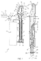
Figure 1 shows a diagram of a machine for packaging pourable food products from a web of packaging material and featuring a sterilizing unit in accordance with the teachings of the present invention; -
Figure 2 shows a larger-scale view in perspective of part of theFigure 1 sterilizing unit; -
Figure 3 shows a vertical section of the part of the sterilizing unit ofFigure 2 ; -
Figure 4 shows a portion of the web of packaging material ofFigure 1 when advancing through the part of the sterilizing unit ofFigure 2 ; -
Figure 5 shows a larger-scale front view of a nozzle of the sterilizing unit ofFigures 1 to 3 ; -
Figure 6 shows a larger-scale detail ofFigure 3 sterilizing unit; and -
Figure 7 shows a front view of a possible variant of theFigure 5 nozzle. - Number 1 in
Figure 1 indicates as a whole a packaging machine for continuously producing aseptic sealed packages of a pourable food product from a web of packaging material 2 (hereafter referred to simply as "web 2"). - Machine 1 comprises a sterilizing unit 3, to which
web 2 is fed off a reel (not shown) along a path P1. - Machine 1 also comprises an application unit 4 for applying reclosable
opening devices 5 toweb 2 and located upstream from the sterilizing unit 3 along path P1. Application unit 4 is conveniently defined by a known station for injection molding plastic material, and through whichweb 2 is fed in steps. At the output of application unit 4, theweb 2 is provided, along an intermediatelongitudinal portion 2a thereof (seeFigures 2 and4 ), with a succession of equally spaced opening devices 5 (only schematically shown inFigures 1 and3 along limited portions of theweb 2; see alsoFigures 2 ,4 and6 for more detailed views of opening devices 5). At the output of application unit 4 and upstream from sterilizing unit 3, a web store 6 is conveniently provided to compensate for the different web feeds of the two units (step feed and continuous feed respectively). - Sterilizing unit 3 basically comprises a
transition chamber 7, into whichweb 2 is first fed, a sterilizing bath 8 containing a liquid sterilizing agent, e.g. a 30% solution of hydrogen peroxide (H2O2) and water, through whichweb 2 is advanced, and anaseptic chamber 9, in whichweb 2 is dried, as explained in detail below. - Bath 8 is substantially defined by a U-shaped conduit filled, in use, with sterilizing agent to a predetermined level. The U-shaped conduit is defined by two vertical, respectively inlet and outlet,
branches top openings web 2 into and out of bath 8, and communicate respectively withtransition chamber 7 andaseptic chamber 9; the twobranches bottom portion 14 of bath 8 housing a horizontal-axis guide roller 15. - Inside bath 8,
web 2 therefore describes a U-shaped path P2 of such a length as to keep the packaging material long enough inside the sterilizing agent. - Bath 8 is connected to a peroxide control circuit 16 - known and therefore not shown in detail - and is maintained, in use, at a controlled temperature, e.g. of around 70°C - 80°C.
-
Aseptic chamber 9 is located abovetransition chamber 7, is separated from it by apartition 17 and has an inlet forweb 2, coincident with the outlet (top opening 13) of bath 8. -
Aseptic chamber 9 comprises atop portion 20, housing drying means 21 for removing residual sterilizing agent fromweb 2 andopening devices 5, and a bottom portion ortower 22 extending vertically and parallel to bath 8, and in whichweb 2 is folded longitudinally into a cylinder and sealed longitudinally to form a continuouscylindrical tube 23 having a vertical axis A. -
Aseptic chamber 9 is maintained slightly above ambient pressure, so that any leakage through the seals occurs outwards as opposed to inwards of the chamber. - As visible in
Figure 1 , insidetop portion 20 ofaseptic chamber 9,web 2 describes first a vertical path P3 extending on the prolongation of the vertical portion of path P2 inoutlet branch 11 and is then diverted byrespective rollers tower 22, parallel to axis A of thetube 23. - In known manner and not described in detail,
tube 23, formed downstream fromroller 25, is filled continuously with the product for packaging by means of afill conduit 26, and comes out downwards through a bottom opening 27 inaseptic chamber 9, of which it substantially forms an extension. - Machine 1 comprises a known transverse form-and-
seal unit 28, not shown in detail, in whichtube 23 of packaging material is gripped between pairs ofjaws 28a, whichseal tube 23 transversely to formaseptic pillow packs 29 eventually formed by known cutting and folding operations into individual packages. - With reference to
Figures 1 to 4 , drying means 21 comprise twoidle squeeze rollers 30 having parallel horizontal axes, located close to the inlet ofaseptic chamber 9, on opposite sides ofweb 2, and at least one of which is covered with relatively soft material.Squeeze rollers 30 exert pressure on respective opposite faces ofweb 2 to squeeze the drops of sterilizing agent out and back into bath 8. - Squeeze rollers 30 (
Figures 2 and4 ) conveniently comprise respectiveintermediate recesses 31 located at intermediatelongitudinal portion 2a ofweb 2 to permit the passage ofopening devices 5 without interfering with therollers 30. In the example shown,recesses 31 are defined by respective smaller-diameter intermediate portions ofsqueeze rollers 30. - As visible in
Figures 1 ,3 and4 , drying means 21 also comprise, in a known manner, twonozzles 32 located at the inlet ofaseptic chamber 9, on opposite sides ofweb 2, immediately upstream fromsqueeze rollers 30 along path P3 and atrecesses 31 of therollers 30. -
Nozzles 32 provide for directing respective streams of air onto intermediatelongitudinal portion 2a ofweb 2, atopening devices 5, to remove residual sterilizing agent from theopening devices 5. In particular,nozzles 32 are configured so as to push the residual sterilizing agent away from theopening devices 5 and towards the opposite sides of theweb 2 and the bath 8. - As shown in
Figures 1 to 3 , drying means 21 also comprise two so-called "air knives" 35 located on opposite sides ofweb 2, downstream fromsqueeze rollers 30 with reference to path P3 and therefore oversuch rollers 30. - Each
air knife 35 comprises arelative nozzle web 2 and, and arelative guide wall web 2 and at reduced distance therefrom so as to guide the relative stream of air, in use, in a direction substantially parallel to theweb 2 but opposite to the travelling direction thereof. - As visible in
Figure 3 ,guide wall 38 is located facing the surfaces ofopening devices 5 designed to be oriented towards the inside of the finished packages and having a concave configuration;guide wall 39 is therefore located facing the opposite surfaces of theopening devices 5, which have a convex configuration. - With reference to
Figures 1 to 4 , drying means 21 further compriseadditional ejecting means 40 arranged at a given distance from the outlet of bath 8 and configured so as to direct a stream of air transversally toweb 2 and onto thelongitudinal portion 2a of theweb 2 provided with theopening devices 5. - Advantageously, ejecting
means 40 are located onguide wall 38 and downstream fromsqueeze rollers 30 along path P3 ofweb 2. - The Applicant has observed that this location permits to increase the drying effect on
opening devices 5 after the most part of residual sterilizing agent has been removed bysqueeze rollers 30. In particular, the zone immediately adjacent to thesqueeze rollers 30 is characterized by a certain level of turbulence due to presence of drops of sterilizing agent; by positioning the additional ejecting means 40 at a given distance from that turbulent zone, and in particular on theair knives 35, permits to obtain an additional drying step on theopening devices 5 without increasing the turbulence at thesqueeze rollers 30. - With reference to
Figures 2 to 6 , ejecting means 40 comprise anozzle 41 housed with play within awindow 42 ofguide wall 38 so as to faceweb 2, and asupply conduit 43 extending insideaseptic chamber 9 from aside wall 44 thereof and carrying, in a projecting manner,nozzle 41. - In particular,
nozzle 41 comprises a hollow box-shaped body 45 having arear opening 46 connected to oneend 47 ofsupply conduit 43; more specifically,rear opening 46 is delimited by a projectingedge 48 engaged byend 47 ofsupply conduit 43 and secured thereto by releasable fastening means 49, such as screws. -
Body 45 is closed at the front by aplate 50 provided with a hollow shapedfront projection 51 communicating with the cavity of thebody 45 and adapted to direct a stream of air ontoweb 2. - In the example shown in the accompanying drawings,
plate 50 has a rectangular profile andprojection 51 is substantially L-shaped with twobranches web 2 and extending in an inclined manner with respect to the travelling direction thereof at the zone ofnozzle 41. - Each
branch relative outlet port relative branch -
Outlet ports Figure 6 ), eachoutlet port web 2 and inclined towards bath 8; as indicated inFigure 6 , the axis B of eachoutlet port web 2. - With particular reference to
Figure 5 ,outlet port 54, which is located upstream ofoutlet port 55 along path P3, defines arelative outlet area 56, from which the stream of air is issued in use and which extends along a direction R parallel toweb 2 and forming an acute angle β, different from zero, with a horizontal direction S parallel to theweb 2 and orthogonal to the travelling direction of theweb 2 at the zone ofnozzle 41. - In an analogous manner,
outlet port 55 defines arelative outlet area 57, from which the stream of air is issued in use and which extends along a direction T parallel toweb 2 and transversal to direction R and to the travelling direction of theweb 2 at the zone ofnozzle 41. - In the example shown,
outlet areas web 2 at the zone ofnozzle 41. - Moreover, as visible in
Figure 5 , direction T forms an angle γ of 90° with direction R. In this way, the stream of air issued fromoutlet area 57 does not interfere with the stream of air issued fromoutlet area 56. - In actual use,
web 2 is fed in steps through application unit 4 where openingdevices 5 are formed, and continuously through bath 8 andaseptic chamber 9. - On entering
aseptic chamber 9,longitudinal portion 2a ofweb 2 withpre-applied opening devices 5 is swept on both faces by the air streams fromnozzles 32; such air streams push the residual sterilizing agent away from the openingdevices 5 and towards the opposite sides of theweb 2 and the bath 8. -
Web 2 is then fed throughsqueeze rollers 30, which squeeze the drops of residual sterilizing agent out and back into bath 8. - At this point,
web 2 enters theair knives 35 and is swept by sterile-air streams ejected fromnozzles web 2 byguide walls - During the passage through
guide walls longitudinal portion 2a ofweb 2 with openingdevices 5 is also swept by the stream of air ejected bynozzle 41. - Due to the opposite inclined configurations of
outlet areas ports opening device 5 is first dried from a first side end to a second side end opposite to the first side end and, then, from this latter side end to the first one. In this manner, the jet of air issued from thedownstream outlet port 55 does not interfere with the jet of air issued from theupstream outlet port 54, so as to make the removal action of the residual sterilizing agent from openingdevices 5 very effective, even with increased output rates of the packaging machine 1. - Once left the
air knives 35, theweb 2 is diverted byroller 24 along path P4 and byroller 25 along path P5. -
Web 2 is then folded into a cylinder and sealed longitudinally to formtube 23, which is filled continuously with the pourable food product fromconduit 26, and is gripped and sealed transversely byjaws 28a to form a succession of pillow packs 29. - The variant of
Figure 7 relates to a different configuration ofnozzle 41, whose front projection, indicated as a whole with 51', differs from correspondingprojection 51 in that it comprises anadditional branch 60 located downstream ofbranch 53 along path P3 and extending parallel tobranch 52. - More specifically, the
additional branch 60 is provided with arelative outlet port 61 in the form of a slot defining arelative outlet area 62 of the same type asoutlet areas web 2 and to direction R, and therefore forming an angle γ of 90° with direction T. - According to a possible alternative not shown, the
front projection 51 ofnozzle 41 may be also formed by a succession of alternatingbranches respective outlet areas - According to another possible alternative not shown, the
front projection 51 ofnozzle 41 may be also formed by asingle branch relative outlet port single outlet area - According to a further possible alternative not shown, each
outlet port relative outlet area - Tests have been carried out on further different configurations of the outlet areas of
nozzle 41, and namely: - a first configuration defined by a succession of horizontal outlet areas, i.e. extending parallel to direction S; and
- a second configuration defined by a succession of parallel and inclined outlet areas, i.e. extending parallel to direction R or direction T.
- These tests have revealed that the above-indicated configurations are less effective than the preferred ones of
Figures 5 and7 . As a matter of fact, in both the tested solutions, the upstream jet of air tends to disturb, or better "to raise", the immediately downstream jet and so on, with the result that theopening devices 5 are not well scavenged by the impinging flow of air. - The advantages of sterilizing unit 3 according to the present invention will be clear from the foregoing description.
- In particular, thanks to the location of
nozzle 41 onguide wall 38 ofair knives 35 at a distance fromsqueeze rollers 30 and to the particular configuration ofoutlet ports respective outlet areas web 2 but inclined with respect to the web travelling direction, a very effective current of air can be directed onto theopening devices 5 arranged on thelongitudinal portion 2a ofweb 2. In this way, the openingdevices 5 are scavenged both in the web travelling direction and laterally with respect to this latter direction. - Moreover, due to the fact that the extension direction T, V of each
outlet area upstream outlet area different outlet areas - Even alongside drastic increases in packaging machine output rates, therefore, sterilizing unit 3 safely ensures ample compliance with current regulations governing the permissible amount of residual sterilizing agent on the packaging material and
opening devices 5 of the finished packages. - Clearly, changes may be made to sterilizing unit 3 as described and illustrated herein without, however, departing from the scope defined in the accompanying claims.
Claims (15)
- A unit (3) for sterilizing a web (2) of packaging material advanced along a given path (P3), said web (2) having, along a longitudinal portion (2a) thereof, a succession of pre-applied opening devices (5) and being adapted to be transformed in a plurality of sealed packages containing a pourable food product, said unit (3) comprising drying means (21) for removing residual sterilizing agent from said web (2), wherein said drying means (21) comprise ejecting means (41) configured so as to direct a stream of air transversally to said web (2) and onto said longitudinal portion (2a) of said web (2) provided with said opening devices (5), said ejecting means (41) comprising at least a first outlet area (56), from which said stream of air is issued and which is elongated along a first direction (R) parallel to said web (2) and transversal to the travelling direction of the web (2) at the zone of said ejecting means (41).
- A unit as claimed in claim 1, wherein said first direction (R) forms an acute angle (β), different from zero, with a second direction (S) parallel to the web (2) and orthogonal to the travelling direction of the web (2) at the zone of said ejecting means (41).
- A unit as claimed in claim 1 or 2, wherein said ejecting means (41) comprise a second outlet area (57) which is elongated along a third direction (T) parallel to said web (2) and transversal to the first direction (R) and to the travelling direction of the web (2) at the zone of said ejecting means (41).
- A unit as claimed in claim 3, wherein said second outlet area (57) is of the same type as the first outlet area (56).
- A unit as claimed in claim 3 or 4, wherein said first outlet area (56) and second outlet area (56, 57) have opposite inclinations with respect to the travelling direction of the web (2).
- A unit as claimed in any one of claims 3 to 5, wherein the stream of air issued from said second outlet area (57) does not interfere with the stream of air issued from said first outlet area (56).
- A unit as claimed in any one of claims 3 to 6, wherein said third direction (T) forms an angle (γ) of 90° with said first direction (R).
- A unit as claimed in any one of claims 3 to 7, wherein said ejecting means (41) comprise a third outlet area (62) which is elongated along a fourth direction (V) parallel to said web (2) and to said first direction (R); said third outlet area (62) being arranged downstream from said second outlet area (57) along said path (P3) of said web (2).
- A unit as claimed in claim 8, wherein said third outlet area (62) is of the same type as said first outlet area (56) and second outlet area (57).
- A unit as claimed in any one of the preceding claims and further comprising a bath (8), containing a sterilizing agent in which said web (2) with said opening devices (5) is advanced, and an aseptic chamber (9) connected to an outlet (13) of said bath (8) and housing said drying means (21).
- A unit as claimed in claim 10, wherein said ejecting means (41) are located at a distance from said outlet (13) of said bath (8).
- A unit as claimed in claim 10 or 11, wherein said ejecting means (41) are so configured to direct said stream of air in an inclined direction towards said bath (8).
- A unit as claimed in any one of claims 10 to 12, wherein said ejecting means (41) comprise at least a first outlet port (54) inclined towards said bath (8).
- A unit as claimed in claim 13, wherein said first outlet port (54) forms an acute angle (α), different from zero, with a fifth direction (Q) orthogonal to the web (2).
- A unit as claimed in claim 13 or 14, wherein said first outlet port (54) is a slot defining said first outlet area (56).
Priority Applications (1)
| Application Number | Priority Date | Filing Date | Title |
|---|---|---|---|
| EP14172121.7A EP2789543B1 (en) | 2011-09-30 | 2011-09-30 | A unit for sterilizing a web of packaging material for a machine for packaging pourable food products |
Applications Claiming Priority (2)
| Application Number | Priority Date | Filing Date | Title |
|---|---|---|---|
| EP14172121.7A EP2789543B1 (en) | 2011-09-30 | 2011-09-30 | A unit for sterilizing a web of packaging material for a machine for packaging pourable food products |
| EP11183645.8A EP2574560B1 (en) | 2011-09-30 | 2011-09-30 | A unit for sterilizing a web of packaging material for a machine for packaging pourable food products |
Related Parent Applications (1)
| Application Number | Title | Priority Date | Filing Date |
|---|---|---|---|
| EP11183645.8A Division EP2574560B1 (en) | 2011-09-30 | 2011-09-30 | A unit for sterilizing a web of packaging material for a machine for packaging pourable food products |
Publications (2)
| Publication Number | Publication Date |
|---|---|
| EP2789543A1 true EP2789543A1 (en) | 2014-10-15 |
| EP2789543B1 EP2789543B1 (en) | 2016-04-27 |
Family
ID=46799221
Family Applications (2)
| Application Number | Title | Priority Date | Filing Date |
|---|---|---|---|
| EP11183645.8A Active EP2574560B1 (en) | 2011-09-30 | 2011-09-30 | A unit for sterilizing a web of packaging material for a machine for packaging pourable food products |
| EP14172121.7A Active EP2789543B1 (en) | 2011-09-30 | 2011-09-30 | A unit for sterilizing a web of packaging material for a machine for packaging pourable food products |
Family Applications Before (1)
| Application Number | Title | Priority Date | Filing Date |
|---|---|---|---|
| EP11183645.8A Active EP2574560B1 (en) | 2011-09-30 | 2011-09-30 | A unit for sterilizing a web of packaging material for a machine for packaging pourable food products |
Country Status (11)
| Country | Link |
|---|---|
| US (1) | US9408932B2 (en) |
| EP (2) | EP2574560B1 (en) |
| JP (1) | JP6013491B2 (en) |
| KR (1) | KR20140072867A (en) |
| CN (1) | CN103842257B (en) |
| BR (1) | BR112014002548A2 (en) |
| ES (1) | ES2493925T3 (en) |
| IN (1) | IN2014CN03045A (en) |
| MX (1) | MX340129B (en) |
| RU (1) | RU2605196C2 (en) |
| WO (1) | WO2013045192A1 (en) |
Families Citing this family (6)
| Publication number | Priority date | Publication date | Assignee | Title |
|---|---|---|---|---|
| ES2503567T3 (en) * | 2011-10-03 | 2014-10-07 | Tetra Laval Holdings & Finance S.A. | Packaging machine and method for producing sealed containers of a food product from a tape of a packaging material |
| IT201800002933A1 (en) * | 2018-02-22 | 2019-08-22 | Gd Spa | Device and method for sterilizing a web of wrapping material |
| US20220249721A1 (en) * | 2019-06-28 | 2022-08-11 | Tetra Laval Holdings & Finance S.A. | A method for removing excess of a sterilization agent from a web of carton-based packaging material and a system thereof |
| IT202200020154A1 (en) * | 2022-09-30 | 2024-03-30 | Ipi Srl | PROCEDURE FOR MAKING CONTAINERS FILLED WITH A PRODUCT AND SEALED |
| IT202400005242A1 (en) * | 2024-03-08 | 2025-09-08 | Tetra Laval Holdings & Finance | NOZZLE, GROUP FOR REMOVING A STERILIZING AGENT FOR A STERILIZATION UNIT AND PACKAGING MACHINE FOR PRODUCTION OF SEALED PACKAGES CONTAINING A POURABLE PRODUCT |
| CN118681047B (en) * | 2024-08-29 | 2024-11-05 | 杭州永创智能设备股份有限公司 | Packaging material sterilization device |
Citations (2)
| Publication number | Priority date | Publication date | Assignee | Title |
|---|---|---|---|---|
| CH511150A (en) * | 1969-07-29 | 1971-08-15 | Alpura Ag | Device for removing sterilization liquid from the surface of sheet-like packaging material to be sterilized inside a sterile chamber |
| EP1050468A1 (en) * | 1999-05-03 | 2000-11-08 | Tetra Laval Holdings & Finance S.A. | Unit for sterilizing strip material on a packaging machine for packaging pourable food products, and packaging machine comprising such a unit |
Family Cites Families (10)
| Publication number | Priority date | Publication date | Assignee | Title |
|---|---|---|---|---|
| SE451125B (en) * | 1983-06-03 | 1987-09-07 | Tetra Pak Ab | DEVICE FOR THE TREATMENT OF A CURRENT PACKAGING MATERIAL COAT WITH MEDIUM FLOWING GAS |
| JP4188454B2 (en) * | 1998-06-03 | 2008-11-26 | 日本テトラパック株式会社 | Method and apparatus for removing liquid from packaging material surface |
| EP1050467B1 (en) * | 1999-05-03 | 2004-03-03 | Tetra Laval Holdings & Finance SA | Unit for sterilizing strip material on a packaging machine for packaging pourable food products, and packaging machine comprising such a unit |
| JP4521948B2 (en) * | 2000-08-08 | 2010-08-11 | 四国化工機株式会社 | Sterilizer removal device |
| US20020124526A1 (en) * | 2001-03-12 | 2002-09-12 | Lewis James D. | Albumin in a flexible polymeric container |
| ES2335479T3 (en) * | 2002-02-08 | 2010-03-29 | TETRA LAVAL HOLDINGS & FINANCE SA | UNIT TO STERILIZE MATERIAL IN THE FORM OF A BAND IN A MACHINE FOR PACKAGING OF VERTIBLE FOOD PRODUCTS. |
| JP2004245545A (en) * | 2003-02-17 | 2004-09-02 | Ichikin Kogyosha:Kk | Hot air processing device |
| ATE435822T1 (en) | 2005-11-29 | 2009-07-15 | Tetra Laval Holdings & Finance | SYSTEM FOR THE STERILIZATION OF PACKAGING MATERIAL FOR A MACHINE FOR PACKAGING A FLOWABLE FOOD |
| EP2119631B1 (en) | 2008-05-15 | 2011-12-21 | Tetra Laval Holdings & Finance SA | Unit and method for sterilizing a web of packaging material for a machine for packaging pourable food products |
| EP2418153B1 (en) * | 2009-04-10 | 2015-11-11 | Orihiro Engineering Co., Ltd. | Aseptic filling packaging machine and aseptic filling packaging method |
-
2011
- 2011-09-30 EP EP11183645.8A patent/EP2574560B1/en active Active
- 2011-09-30 EP EP14172121.7A patent/EP2789543B1/en active Active
- 2011-09-30 ES ES11183645.8T patent/ES2493925T3/en active Active
-
2012
- 2012-08-29 CN CN201280047629.0A patent/CN103842257B/en active Active
- 2012-08-29 JP JP2014532298A patent/JP6013491B2/en active Active
- 2012-08-29 US US14/238,399 patent/US9408932B2/en active Active
- 2012-08-29 WO PCT/EP2012/066758 patent/WO2013045192A1/en not_active Ceased
- 2012-08-29 MX MX2014003265A patent/MX340129B/en active IP Right Grant
- 2012-08-29 RU RU2014117539/13A patent/RU2605196C2/en not_active IP Right Cessation
- 2012-08-29 BR BR112014002548A patent/BR112014002548A2/en not_active IP Right Cessation
- 2012-08-29 KR KR1020147004877A patent/KR20140072867A/en not_active Ceased
- 2012-08-29 IN IN3045CHN2014 patent/IN2014CN03045A/en unknown
Patent Citations (2)
| Publication number | Priority date | Publication date | Assignee | Title |
|---|---|---|---|---|
| CH511150A (en) * | 1969-07-29 | 1971-08-15 | Alpura Ag | Device for removing sterilization liquid from the surface of sheet-like packaging material to be sterilized inside a sterile chamber |
| EP1050468A1 (en) * | 1999-05-03 | 2000-11-08 | Tetra Laval Holdings & Finance S.A. | Unit for sterilizing strip material on a packaging machine for packaging pourable food products, and packaging machine comprising such a unit |
Also Published As
| Publication number | Publication date |
|---|---|
| MX2014003265A (en) | 2014-04-30 |
| RU2014117539A (en) | 2015-11-10 |
| US20140199215A1 (en) | 2014-07-17 |
| BR112014002548A2 (en) | 2017-03-14 |
| EP2789543B1 (en) | 2016-04-27 |
| ES2493925T3 (en) | 2014-09-12 |
| CN103842257B (en) | 2016-02-10 |
| RU2605196C2 (en) | 2016-12-20 |
| KR20140072867A (en) | 2014-06-13 |
| IN2014CN03045A (en) | 2015-07-03 |
| WO2013045192A1 (en) | 2013-04-04 |
| EP2574560A1 (en) | 2013-04-03 |
| CN103842257A (en) | 2014-06-04 |
| EP2574560B1 (en) | 2014-06-25 |
| JP6013491B2 (en) | 2016-10-25 |
| MX340129B (en) | 2016-06-28 |
| JP2014528878A (en) | 2014-10-30 |
| US9408932B2 (en) | 2016-08-09 |
Similar Documents
| Publication | Publication Date | Title |
|---|---|---|
| US8518325B2 (en) | Method of sterilizing a web of packaging material | |
| US6354061B1 (en) | Unit for sterilizing strip material on a packaging machine | |
| US9408932B2 (en) | Unit for sterilizing a web of packaging material for a machine for packaging pourable food products | |
| EP1050468B1 (en) | Unit for sterilizing strip material on a packaging machine for packaging pourable food products, and packaging machine comprising such a unit | |
| KR20040086335A (en) | Unit for sterilizing web-fed material on a machine for packaging pourable food products | |
| EP1795448B1 (en) | Air processing circuit for a sterilizing unit for sterilizing sheet packaging materials for packaging pourable food products, and sterilizing unit featuring such a circuit | |
| EP3367031A1 (en) | A drying unit for sterilizing a web of packaging material for packaging liquid food products | |
| HK1126175B (en) | Packaging material sterilizing unit for a pourable food product packaging machine | |
| HK1032373B (en) | Unit for sterilizing strip material on a packaging machine for packaging pourable food products, and packaging machine comprising such a unit | |
| HK1033928B (en) | Unit for sterilizing strip material on a packaging machine for packaging pourable food products, and packaging machine comprising such a unit | |
| EP3075669A1 (en) | Machine and method for packaging pourable food products in sealed containers formed from a tube of packaging material |
Legal Events
| Date | Code | Title | Description |
|---|---|---|---|
| PUAI | Public reference made under article 153(3) epc to a published international application that has entered the european phase |
Free format text: ORIGINAL CODE: 0009012 |
|
| 17P | Request for examination filed |
Effective date: 20140612 |
|
| AC | Divisional application: reference to earlier application |
Ref document number: 2574560 Country of ref document: EP Kind code of ref document: P |
|
| AK | Designated contracting states |
Kind code of ref document: A1 Designated state(s): AL AT BE BG CH CY CZ DE DK EE ES FI FR GB GR HR HU IE IS IT LI LT LU LV MC MK MT NL NO PL PT RO RS SE SI SK SM TR |
|
| R17P | Request for examination filed (corrected) |
Effective date: 20150415 |
|
| RBV | Designated contracting states (corrected) |
Designated state(s): AL AT BE BG CH CY CZ DE DK EE ES FI FR GB GR HR HU IE IS IT LI LT LU LV MC MK MT NL NO PL PT RO RS SE SI SK SM TR |
|
| RIC1 | Information provided on ipc code assigned before grant |
Ipc: B65B 55/10 20060101AFI20150814BHEP |
|
| GRAP | Despatch of communication of intention to grant a patent |
Free format text: ORIGINAL CODE: EPIDOSNIGR1 |
|
| INTG | Intention to grant announced |
Effective date: 20151211 |
|
| GRAS | Grant fee paid |
Free format text: ORIGINAL CODE: EPIDOSNIGR3 |
|
| GRAA | (expected) grant |
Free format text: ORIGINAL CODE: 0009210 |
|
| AC | Divisional application: reference to earlier application |
Ref document number: 2574560 Country of ref document: EP Kind code of ref document: P |
|
| AK | Designated contracting states |
Kind code of ref document: B1 Designated state(s): AL AT BE BG CH CY CZ DE DK EE ES FI FR GB GR HR HU IE IS IT LI LT LU LV MC MK MT NL NO PL PT RO RS SE SI SK SM TR |
|
| REG | Reference to a national code |
Ref country code: GB Ref legal event code: FG4D |
|
| REG | Reference to a national code |
Ref country code: CH Ref legal event code: EP |
|
| REG | Reference to a national code |
Ref country code: AT Ref legal event code: REF Ref document number: 794498 Country of ref document: AT Kind code of ref document: T Effective date: 20160515 |
|
| REG | Reference to a national code |
Ref country code: IE Ref legal event code: FG4D |
|
| REG | Reference to a national code |
Ref country code: DE Ref legal event code: R096 Ref document number: 602011026082 Country of ref document: DE |
|
| REG | Reference to a national code |
Ref country code: FR Ref legal event code: PLFP Year of fee payment: 6 |
|
| REG | Reference to a national code |
Ref country code: LT Ref legal event code: MG4D |
|
| REG | Reference to a national code |
Ref country code: NL Ref legal event code: MP Effective date: 20160427 |
|
| REG | Reference to a national code |
Ref country code: AT Ref legal event code: MK05 Ref document number: 794498 Country of ref document: AT Kind code of ref document: T Effective date: 20160427 |
|
| PG25 | Lapsed in a contracting state [announced via postgrant information from national office to epo] |
Ref country code: NL Free format text: LAPSE BECAUSE OF FAILURE TO SUBMIT A TRANSLATION OF THE DESCRIPTION OR TO PAY THE FEE WITHIN THE PRESCRIBED TIME-LIMIT Effective date: 20160427 |
|
| PG25 | Lapsed in a contracting state [announced via postgrant information from national office to epo] |
Ref country code: NO Free format text: LAPSE BECAUSE OF FAILURE TO SUBMIT A TRANSLATION OF THE DESCRIPTION OR TO PAY THE FEE WITHIN THE PRESCRIBED TIME-LIMIT Effective date: 20160727 Ref country code: PL Free format text: LAPSE BECAUSE OF FAILURE TO SUBMIT A TRANSLATION OF THE DESCRIPTION OR TO PAY THE FEE WITHIN THE PRESCRIBED TIME-LIMIT Effective date: 20160427 Ref country code: LT Free format text: LAPSE BECAUSE OF FAILURE TO SUBMIT A TRANSLATION OF THE DESCRIPTION OR TO PAY THE FEE WITHIN THE PRESCRIBED TIME-LIMIT Effective date: 20160427 Ref country code: FI Free format text: LAPSE BECAUSE OF FAILURE TO SUBMIT A TRANSLATION OF THE DESCRIPTION OR TO PAY THE FEE WITHIN THE PRESCRIBED TIME-LIMIT Effective date: 20160427 |
|
| PG25 | Lapsed in a contracting state [announced via postgrant information from national office to epo] |
Ref country code: AT Free format text: LAPSE BECAUSE OF FAILURE TO SUBMIT A TRANSLATION OF THE DESCRIPTION OR TO PAY THE FEE WITHIN THE PRESCRIBED TIME-LIMIT Effective date: 20160427 Ref country code: SE Free format text: LAPSE BECAUSE OF FAILURE TO SUBMIT A TRANSLATION OF THE DESCRIPTION OR TO PAY THE FEE WITHIN THE PRESCRIBED TIME-LIMIT Effective date: 20160427 Ref country code: GR Free format text: LAPSE BECAUSE OF FAILURE TO SUBMIT A TRANSLATION OF THE DESCRIPTION OR TO PAY THE FEE WITHIN THE PRESCRIBED TIME-LIMIT Effective date: 20160728 Ref country code: PT Free format text: LAPSE BECAUSE OF FAILURE TO SUBMIT A TRANSLATION OF THE DESCRIPTION OR TO PAY THE FEE WITHIN THE PRESCRIBED TIME-LIMIT Effective date: 20160829 Ref country code: ES Free format text: LAPSE BECAUSE OF FAILURE TO SUBMIT A TRANSLATION OF THE DESCRIPTION OR TO PAY THE FEE WITHIN THE PRESCRIBED TIME-LIMIT Effective date: 20160427 Ref country code: LV Free format text: LAPSE BECAUSE OF FAILURE TO SUBMIT A TRANSLATION OF THE DESCRIPTION OR TO PAY THE FEE WITHIN THE PRESCRIBED TIME-LIMIT Effective date: 20160427 Ref country code: RS Free format text: LAPSE BECAUSE OF FAILURE TO SUBMIT A TRANSLATION OF THE DESCRIPTION OR TO PAY THE FEE WITHIN THE PRESCRIBED TIME-LIMIT Effective date: 20160427 Ref country code: HR Free format text: LAPSE BECAUSE OF FAILURE TO SUBMIT A TRANSLATION OF THE DESCRIPTION OR TO PAY THE FEE WITHIN THE PRESCRIBED TIME-LIMIT Effective date: 20160427 |
|
| PG25 | Lapsed in a contracting state [announced via postgrant information from national office to epo] |
Ref country code: BE Free format text: LAPSE BECAUSE OF FAILURE TO SUBMIT A TRANSLATION OF THE DESCRIPTION OR TO PAY THE FEE WITHIN THE PRESCRIBED TIME-LIMIT Effective date: 20160427 |
|
| REG | Reference to a national code |
Ref country code: DE Ref legal event code: R097 Ref document number: 602011026082 Country of ref document: DE |
|
| PG25 | Lapsed in a contracting state [announced via postgrant information from national office to epo] |
Ref country code: RO Free format text: LAPSE BECAUSE OF FAILURE TO SUBMIT A TRANSLATION OF THE DESCRIPTION OR TO PAY THE FEE WITHIN THE PRESCRIBED TIME-LIMIT Effective date: 20160427 Ref country code: SK Free format text: LAPSE BECAUSE OF FAILURE TO SUBMIT A TRANSLATION OF THE DESCRIPTION OR TO PAY THE FEE WITHIN THE PRESCRIBED TIME-LIMIT Effective date: 20160427 Ref country code: CZ Free format text: LAPSE BECAUSE OF FAILURE TO SUBMIT A TRANSLATION OF THE DESCRIPTION OR TO PAY THE FEE WITHIN THE PRESCRIBED TIME-LIMIT Effective date: 20160427 Ref country code: EE Free format text: LAPSE BECAUSE OF FAILURE TO SUBMIT A TRANSLATION OF THE DESCRIPTION OR TO PAY THE FEE WITHIN THE PRESCRIBED TIME-LIMIT Effective date: 20160427 Ref country code: DK Free format text: LAPSE BECAUSE OF FAILURE TO SUBMIT A TRANSLATION OF THE DESCRIPTION OR TO PAY THE FEE WITHIN THE PRESCRIBED TIME-LIMIT Effective date: 20160427 |
|
| PG25 | Lapsed in a contracting state [announced via postgrant information from national office to epo] |
Ref country code: SM Free format text: LAPSE BECAUSE OF FAILURE TO SUBMIT A TRANSLATION OF THE DESCRIPTION OR TO PAY THE FEE WITHIN THE PRESCRIBED TIME-LIMIT Effective date: 20160427 |
|
| PLBE | No opposition filed within time limit |
Free format text: ORIGINAL CODE: 0009261 |
|
| STAA | Information on the status of an ep patent application or granted ep patent |
Free format text: STATUS: NO OPPOSITION FILED WITHIN TIME LIMIT |
|
| 26N | No opposition filed |
Effective date: 20170130 |
|
| PG25 | Lapsed in a contracting state [announced via postgrant information from national office to epo] |
Ref country code: MC Free format text: LAPSE BECAUSE OF FAILURE TO SUBMIT A TRANSLATION OF THE DESCRIPTION OR TO PAY THE FEE WITHIN THE PRESCRIBED TIME-LIMIT Effective date: 20160427 |
|
| REG | Reference to a national code |
Ref country code: CH Ref legal event code: PL |
|
| GBPC | Gb: european patent ceased through non-payment of renewal fee |
Effective date: 20160930 |
|
| PG25 | Lapsed in a contracting state [announced via postgrant information from national office to epo] |
Ref country code: SI Free format text: LAPSE BECAUSE OF FAILURE TO SUBMIT A TRANSLATION OF THE DESCRIPTION OR TO PAY THE FEE WITHIN THE PRESCRIBED TIME-LIMIT Effective date: 20160427 |
|
| REG | Reference to a national code |
Ref country code: IE Ref legal event code: MM4A |
|
| PG25 | Lapsed in a contracting state [announced via postgrant information from national office to epo] |
Ref country code: LI Free format text: LAPSE BECAUSE OF NON-PAYMENT OF DUE FEES Effective date: 20160930 Ref country code: IE Free format text: LAPSE BECAUSE OF NON-PAYMENT OF DUE FEES Effective date: 20160930 Ref country code: GB Free format text: LAPSE BECAUSE OF NON-PAYMENT OF DUE FEES Effective date: 20160930 Ref country code: CH Free format text: LAPSE BECAUSE OF NON-PAYMENT OF DUE FEES Effective date: 20160930 |
|
| REG | Reference to a national code |
Ref country code: FR Ref legal event code: PLFP Year of fee payment: 7 |
|
| PG25 | Lapsed in a contracting state [announced via postgrant information from national office to epo] |
Ref country code: LU Free format text: LAPSE BECAUSE OF NON-PAYMENT OF DUE FEES Effective date: 20160930 |
|
| PG25 | Lapsed in a contracting state [announced via postgrant information from national office to epo] |
Ref country code: HU Free format text: LAPSE BECAUSE OF FAILURE TO SUBMIT A TRANSLATION OF THE DESCRIPTION OR TO PAY THE FEE WITHIN THE PRESCRIBED TIME-LIMIT; INVALID AB INITIO Effective date: 20110930 |
|
| PG25 | Lapsed in a contracting state [announced via postgrant information from national office to epo] |
Ref country code: MK Free format text: LAPSE BECAUSE OF FAILURE TO SUBMIT A TRANSLATION OF THE DESCRIPTION OR TO PAY THE FEE WITHIN THE PRESCRIBED TIME-LIMIT Effective date: 20160427 Ref country code: CY Free format text: LAPSE BECAUSE OF FAILURE TO SUBMIT A TRANSLATION OF THE DESCRIPTION OR TO PAY THE FEE WITHIN THE PRESCRIBED TIME-LIMIT Effective date: 20160427 Ref country code: IS Free format text: LAPSE BECAUSE OF FAILURE TO SUBMIT A TRANSLATION OF THE DESCRIPTION OR TO PAY THE FEE WITHIN THE PRESCRIBED TIME-LIMIT Effective date: 20160427 Ref country code: MT Free format text: LAPSE BECAUSE OF NON-PAYMENT OF DUE FEES Effective date: 20160930 |
|
| PG25 | Lapsed in a contracting state [announced via postgrant information from national office to epo] |
Ref country code: BG Free format text: LAPSE BECAUSE OF FAILURE TO SUBMIT A TRANSLATION OF THE DESCRIPTION OR TO PAY THE FEE WITHIN THE PRESCRIBED TIME-LIMIT Effective date: 20160427 |
|
| REG | Reference to a national code |
Ref country code: FR Ref legal event code: PLFP Year of fee payment: 8 |
|
| PG25 | Lapsed in a contracting state [announced via postgrant information from national office to epo] |
Ref country code: TR Free format text: LAPSE BECAUSE OF FAILURE TO SUBMIT A TRANSLATION OF THE DESCRIPTION OR TO PAY THE FEE WITHIN THE PRESCRIBED TIME-LIMIT Effective date: 20160427 Ref country code: AL Free format text: LAPSE BECAUSE OF FAILURE TO SUBMIT A TRANSLATION OF THE DESCRIPTION OR TO PAY THE FEE WITHIN THE PRESCRIBED TIME-LIMIT Effective date: 20160427 |
|
| PGFP | Annual fee paid to national office [announced via postgrant information from national office to epo] |
Ref country code: FR Payment date: 20180813 Year of fee payment: 8 |
|
| PG25 | Lapsed in a contracting state [announced via postgrant information from national office to epo] |
Ref country code: FR Free format text: LAPSE BECAUSE OF NON-PAYMENT OF DUE FEES Effective date: 20190930 |
|
| P01 | Opt-out of the competence of the unified patent court (upc) registered |
Effective date: 20230426 |
|
| PGFP | Annual fee paid to national office [announced via postgrant information from national office to epo] |
Ref country code: DE Payment date: 20250926 Year of fee payment: 15 |
|
| PGFP | Annual fee paid to national office [announced via postgrant information from national office to epo] |
Ref country code: IT Payment date: 20250922 Year of fee payment: 15 |