EP2789492A1 - Antriebssystem für ein Kraftfahrzeug - Google Patents
Antriebssystem für ein Kraftfahrzeug Download PDFInfo
- Publication number
- EP2789492A1 EP2789492A1 EP14000132.2A EP14000132A EP2789492A1 EP 2789492 A1 EP2789492 A1 EP 2789492A1 EP 14000132 A EP14000132 A EP 14000132A EP 2789492 A1 EP2789492 A1 EP 2789492A1
- Authority
- EP
- European Patent Office
- Prior art keywords
- drive
- drive system
- motor
- clutch
- electric motor
- Prior art date
- Legal status (The legal status is an assumption and is not a legal conclusion. Google has not performed a legal analysis and makes no representation as to the accuracy of the status listed.)
- Granted
Links
Images

Classifications
-
- B—PERFORMING OPERATIONS; TRANSPORTING
- B60—VEHICLES IN GENERAL
- B60K—ARRANGEMENT OR MOUNTING OF PROPULSION UNITS OR OF TRANSMISSIONS IN VEHICLES; ARRANGEMENT OR MOUNTING OF PLURAL DIVERSE PRIME-MOVERS IN VEHICLES; AUXILIARY DRIVES FOR VEHICLES; INSTRUMENTATION OR DASHBOARDS FOR VEHICLES; ARRANGEMENTS IN CONNECTION WITH COOLING, AIR INTAKE, GAS EXHAUST OR FUEL SUPPLY OF PROPULSION UNITS IN VEHICLES
- B60K25/00—Auxiliary drives
- B60K25/02—Auxiliary drives directly from an engine shaft
-
- B—PERFORMING OPERATIONS; TRANSPORTING
- B60—VEHICLES IN GENERAL
- B60K—ARRANGEMENT OR MOUNTING OF PROPULSION UNITS OR OF TRANSMISSIONS IN VEHICLES; ARRANGEMENT OR MOUNTING OF PLURAL DIVERSE PRIME-MOVERS IN VEHICLES; AUXILIARY DRIVES FOR VEHICLES; INSTRUMENTATION OR DASHBOARDS FOR VEHICLES; ARRANGEMENTS IN CONNECTION WITH COOLING, AIR INTAKE, GAS EXHAUST OR FUEL SUPPLY OF PROPULSION UNITS IN VEHICLES
- B60K25/00—Auxiliary drives
- B60K2025/005—Auxiliary drives driven by electric motors forming part of the propulsion unit
Definitions
- the invention relates to a drive system for a motor vehicle, preferably a commercial vehicle.
- FIG. 1 shows a schematic representation of a known from the prior art drive system 1 '.
- the drive system 1 ' comprises an internal combustion engine 10' for driving the motor vehicle and at least two auxiliary units N1 ', N2'.
- the internal combustion engine 10 ' serves to drive the ancillaries N1', N2 'via a non-shiftable clutch T1' and a shiftable clutch T2 '.
- a disadvantage of the drive system 1 ' is that the ancillaries N1', N2 'can not be driven as needed, in particular not speed-controlled.
- An object of the invention is to provide an improved and / or alternative drive system for a motor vehicle, preferably a commercial vehicle.
- the invention provides a drive system for a motor vehicle, preferably a commercial vehicle.
- the drive system comprises at least one drive motor (for example, an internal combustion engine and / or an electric drive machine) for driving the motor vehicle and at least two ancillary units.
- the drive system is characterized in particular by the fact that it has an electric motor and is designed so that at least one of the auxiliary units is selectively driven by the drive motor or the electric motor.
- the drive system comprises a first shiftable clutch for coupling and uncoupling the drive motor and a second shiftable clutch for coupling and decoupling the electric motor, whereby at least one of the auxiliary devices is expediently driven selectively by the drive motor or the electric motor.
- the two ancillaries are preferably drivable via a common drive shaft.
- the common drive shaft is suitably driven either via the drive motor and the first clutch and the electric motor and the second clutch.
- the common drive shaft is coupled to a third shiftable clutch, via which either at least one of the auxiliary units can be driven.
- the third clutch is used in particular to selectively drive one auxiliary unit and / or the other auxiliary unit.
- the optionally connectable or disconnectable auxiliary unit expediently does not correspond to a permanent consumer, but is temporarily switchable on demand.
- the electric motor is preferably designed such that it can synchronize the first clutch, the second clutch and / or the third clutch, for example during a mode change between an electromotive drive and a drive motor drive of at least one of the auxiliary units.
- the accessories comprise an auxiliary consumer (e.g., a power steering pump assembly) of appropriately low load (e.g., ⁇ 1 kW) and a temporarily connectable accessory (e.g., an air compressor assembly) of appropriately high load (e.g.,> 3kW).
- auxiliary consumer e.g., a power steering pump assembly
- a temporarily connectable accessory e.g., an air compressor assembly
- one of the ancillaries is an air compressor unit and / or another of the ancillaries a power steering pump unit.
- the drive system comprises a demand control (on-demand power control) and at least one accessory in drive motor pull phases by means of the demand control demand driven and / or speed controlled via the electric motor is driven, preferably without additional mechanical control / regulation unit or in the accessory (s).
- the demand control preferably also includes a demand regulation.
- At least one auxiliary unit is preferably driven via the drive motor.
- the invention is not limited to a drive system but also includes a motor vehicle, preferably a utility vehicle, e.g. a truck or omnibus with a drive system as disclosed herein.
- a motor vehicle preferably a utility vehicle, e.g. a truck or omnibus with a drive system as disclosed herein.
- FIG. 2 shows a schematic view of a drive system 1 for a motor vehicle, preferably a commercial vehicle, such as a truck or a bus, according to an embodiment of the invention.
- the drive system 1 comprises a drive motor 10 for driving the motor vehicle, preferably an internal combustion engine.
- the drive motor 10 could alternatively or additionally also be an electric drive machine for driving the motor vehicle.
- the drive system 1 further comprises at least two ancillaries N1 and N2.
- the auxiliary unit N1 is preferably an air compressor auxiliary unit, while the auxiliary unit N2 is preferably a power-assisted pump sub-unit.
- the drive system 1 further comprises an electric motor 11 and is designed so that the two auxiliary units N1, N2 can be selectively driven by either the drive motor 10 or the electric motor 11.
- the internal combustion engine 10 is connected via a drive shaft W4 with a switchable first clutch K1, while the electric motor 11 is connected via a drive shaft W5 with a switchable second clutch K2.
- the first clutch K1 serves to couple the drive motor 10 on and off, while the second clutch K2 serves to the electric motor 11 on and off.
- the ancillaries N1, N2 can be driven by a common drive shaft W3.
- the common drive shaft W3 can be driven either via the internal combustion engine 10 and the first clutch K1 or the electric motor 11 and the second clutch K2.
- the common drive shaft W3 is connected to a third shiftable clutch K3.
- the third switchable clutch K3 serves to drive either one accessory N1 or the other accessory N2 or both ancillaries N1, N2 at the same time.
- the third clutch K3 is connected via a drive shaft W2 with the auxiliary unit N2 and with a drive shaft W1 with the auxiliary unit N1.
- the drive system 1 also has a demand control, not shown, in particular a so-called on-demand power control for the ancillaries N1, N2.
- the drive system 1 is designed so that it drives the ancillaries N1, N2 in engine traction phases by means of the demand control demand-dependent and in particular speed-controlled via the electric motor 11, while the ancillaries N1, N2 are driven by the internal combustion engine 10 in engine overrun phases.
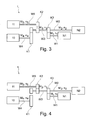
- the electric motor 11 is designed to synchronize the first clutch K1, the second clutch K2 and the third clutch K3, in particular during a mode change between an engine drive mode (FIG. FIG. 3 ) and an electric motor drive mode ( FIG. 4 ).
- FIG. 3 shows a schematic view of the drive system 1 from FIG. 2 ,
- the second clutch K2 is released, so that the electric motor 11 is decoupled.
- the first clutch K1 is closed, so that the internal combustion engine 10 is coupled.
- the internal combustion engine 10 drives both the auxiliary unit N1 and the auxiliary unit N2 via the shaft W3 and the closed clutch K3.
- FIG. 3 thus shows an engine drive mode. In this state, a demand-dependent, in particular speed-controlled operation of the ancillaries N1, N2 purely on the shaft W3 is not possible. For this purpose, additional mechanical controller in the auxiliary units N1, N2 would be necessary.
- FIG. 4 shows a schematic view of the drive system 1 from FIG. 2 ,
- the second clutch K2 is closed, so that the electric motor 11 is coupled.
- the first clutch K1 is released, so that the internal combustion engine 10 is decoupled.
- the electric motor 11 drives both the auxiliary unit N1 and the auxiliary unit N2 via the shaft W3 and the closed clutch K3.
- FIG. 3 thus shows an electric motor drive mode. In this state, a demand-dependent, in particular speed-controlled operation of the auxiliary units N1, N2 is possible, without additional effort of a mechanical regulator in the auxiliary units N1, N2. On-demand operation also enables fuel saving potential.
- switchable clutches K1, K2 and K3 may be gear-based or toothed belt-based.
Landscapes
- Engineering & Computer Science (AREA)
- Chemical & Material Sciences (AREA)
- Combustion & Propulsion (AREA)
- Transportation (AREA)
- Mechanical Engineering (AREA)
- Electric Propulsion And Braking For Vehicles (AREA)
- Hybrid Electric Vehicles (AREA)
Abstract
Description
- Die Erfindung betrifft ein Antriebssystem für ein Kraftfahrzeug, vorzugsweise ein Nutzfahrzeug.
-
Figur 1 zeigt eine schematische Darstellung eines aus dem Stand der Technik bekannten Antriebssystems 1'. Das Antriebssystem 1' umfasst einen Verbrennungsmotor 10' zum Antreiben des Kraftfahrzeugs und zumindest zwei Nebenaggregate N1', N2'. Der Verbrennungsmotor 10' dient dazu, über eine nicht-schaltbare Kupplung T1' und eine schaltbare Kupplung T2' die Nebenaggregate N1', N2' anzutreiben. Nachteilhaft an dem Antriebssystem 1' ist, dass die Nebenaggregate N1', N2' nicht bedarfsabhängig, insbesondere nicht drehzahlgeregelt angetrieben werden können. - Eine Aufgabe der Erfindung ist es, ein verbessertes und/oder alternatives Antriebssystem für ein Kraftfahrzeug, vorzugsweise Nutzfahrzeug, zu schaffen.
- Diese Aufgabe kann mit den Merkmalen des Hauptanspruchs gelöst werden. Vorteilhafte Weiterbildungen der Erfindung können den Unteransprüchen und der folgenden Beschreibung entnommen werden.
- Die Erfindung schafft ein Antriebssystem für ein Kraftfahrzeug, vorzugsweise ein Nutzfahrzeug. Das Antriebssystem umfasst zumindest einen Antriebsmotor (z.B. einen Verbrennungsmotor und/oder eine Elektroantriebsmaschine) zum Antreiben des Kraftfahrzeugs und zumindest zwei Nebenaggregate. Das Antriebssystem zeichnet sich insbesondere dadurch aus, dass es einen Elektromotor aufweist und so ausgeführt ist, dass zumindest eines der Nebenaggregate wahlweise von dem Antriebsmotor oder dem Elektromotor antreibbar ist.
- Mittels des erfindungsgemäßen Antriebssystems können vorzugsweise ein oder mehrere der folgenden Vorteile erzielt werden:
- Reduzierte Hardwarekosten für Elektro-Hybrid-Kraftfahrzeug-Anwendungen, wo elektrisch angetriebene Nebenaggregate vorteilhaft oder erforderlich sind.
- Es ist nur ein Elektromotor zweckmäßig mit Inverter erforderlich, um mehrere Nebenaggregate antreiben zu können.
- Der Elektromotor ermöglicht den Betrieb insbesondere eines Luftpresseraggregats während Niederlastzyklen (low-load cycles) gemeinsam mit einem Lenkhilfspumpenaggregat. So ist z.B. das Lenkhilfspumpenaggregat ein Dauerverbraucher mit überwiegend geringer Last (z.B. <1 kW) und weist nur extrem selten Lastspitzen (z.B. >3kW) auf. Das Luftpresseraggregat hingegen ist ein Verbraucher mit kontinuierlich hoher Last (z.B. >3kW), welcher nicht dauerhaft, sondern nur temporär hinzugeschaltet werden muss. Ein optimierter Luftpresser-Lastzyklus mittels des Antriebssystems ermöglicht eine kleinere Elektromotor-Auslegung für den Elektromotor-Antrieb der Nebenaggregate. Extreme Verbraucherspitzen können über den Antriebsmotor abgefangen werden.
- Es ist möglich, dass das Antriebssystem eine erste schaltbare Kupplung zum An- und Abkoppeln des Antriebsmotors und eine zweite schaltbare Kupplung zum An- und Abkoppeln des Elektromotors aufweist, wodurch zumindest eines der Nebenaggregate zweckmäßig wahlweise von dem Antriebsmotor oder dem Elektromotor antreibbar ist.
- Die zwei Nebenaggregate sind vorzugsweise über eine gemeinsame Triebwelle antreibbar. Die gemeinsame Triebwelle ist zweckmäßig wahlweise über den Antriebsmotor und die erste Kupplung und den Elektromotor und die zweite Kupplung antreibbar.
- Es ist möglich, dass die gemeinsame Triebwelle an eine dritte schaltbare Kupplung gekoppelt ist, über die wahlweise zumindest eines der Nebenaggregate antreibbar ist. Die dritte Kupplung dient insbesondere dazu, wahlweise das eine Nebenaggregat und/oder das andere Nebenaggregat anzutreiben. Das wahlweise an- oder abkoppelbare Nebenaggregat entspricht zweckmäßig keinem Dauerverbraucher, sondern ist temporär, bedarfsabhängig zuschaltbar.
- Der Elektromotor ist vorzugsweise so ausgeführt, dass er die erste Kupplung, die zweite Kupplung und/oder die dritte Kupplung synchronisieren kann, z.B. während eines Moduswechsels zwischen einem elektromotorischen Antrieb und einem antriebsmotorischen Antrieb zumindest eines der Nebenaggregate.
- Es ist möglich, dass die Nebenaggregate ein als Dauerverbraucher wirkendes Nebenaggregat (z.B. ein Lenkhilfspumpenaggregat) mit zweckmäßig geringer Last (z.B. <1 kW) und ein temporär zuschaltbares Nebenaggregat (z.B. ein Luftkompressoraggregat) mit zweckmäßig hoher Last (z.B. >3kW) umfassen.
- Vorzugsweise ist eines der Nebenaggregate ein Luftkompressoraggregat und/oder ein anderes der Nebenaggregate ein Lenkhilfspumpenaggregat.
- Es ist möglich, dass das Antriebssystem eine Bedarfssteuerung (on-demand power control) umfasst und zumindest ein Nebenaggregat in Antriebsmotor-Zugphasen mittels der Bedarfssteuerung bedarfsabhängig und/oder drehzahlgeregelt über den Elektromotor antreibbar ist und zwar vorzugsweise ohne zusätzliche mechanische Steuer-/Regeleinheit an oder in dem oder den Nebenaggregaten. Im Rahmen der Erfindung umfasst die Bedarfssteuerung vorzugsweise auch eine Bedarfsregelung.
- In Antriebsmotor-Schubphasen wird zumindest ein Nebenaggregat vorzugsweise über den Antriebsmotor angetrieben.
- Die Erfindung ist nicht auf ein Antriebssystem beschränkt, sondern umfasst auch ein Kraftfahrzeug, vorzugsweise ein Nutzfahrzeug, z.B. einen Lastkraftwagen oder einen Omnibus, mit einem Antriebssystem wie hierin offenbart.
- Die oben beschriebenen Ausführungsformen der Erfindung sind beliebig miteinander kombinierbar. Andere vorteilhafte Weiterbildungen der Erfindung sind in den Unteransprüchen offenbart oder ergeben sich aus der folgenden Beschreibung bevorzugter Ausführungsformen der Erfindung in Verbindung mit den beigefügten Figuren.
- Figur 1
- zeigt eine schematische Ansicht eines Antriebssystems für ein Kraftfahrzeug gemäß Stand der Technik,
- Figur 2
- zeigt eine schematische Ansicht eines Antriebssystems für ein Kraftfahrzeug gemäß einer Ausführungsform der Erfindung,
- Figur 3
- zeigt eine schematische Ansicht des Antriebssystems aus
Figur 2 im Antriebsmotor-Antriebsmodus und - Figur 4
- zeigt eine schematische Ansicht des Antriebssystems aus
Figur 2 im Elektromotor-Antriebsmodus. -
Figur 2 zeigt eine schematische Ansicht eines Antriebssystems 1 für ein Kraftfahrzeug, vorzugsweise ein Nutzfahrzeug, wie etwa einen Lastkraftwagen oder einen Omnibus, gemäß einer Ausführungsform der Erfindung. - Das Antriebssystem 1 umfasst einen Antriebsmotor 10 zum Antreiben des Kraftfahrzeugs, vorzugsweise einen Verbrennungsmotor. Der Antriebsmotor 10 könnte alternativ oder ergänzend auch eine Elektroantriebsmaschine zum Antreiben des Kraftfahrzeugs sein.
- Das Antriebssystem 1 umfasst ferner zumindest zwei Nebenaggregate N1 und N2. Das Nebenaggregat N1 ist vorzugsweise ein Luftkompressornebenaggregat, während das Nebenaggregat N2 vorzugsweise ein Lenkhilfspumpennebenaggregat ist.
- Das Antriebssystem 1 umfasst ferner einen Elektromotor 11 und ist so ausgeführt, dass die zwei Nebenaggregate N1, N2 wahlweise entweder von dem Antriebsmotor 10 oder dem Elektromotor 11 angetrieben werden können.
- Der Verbrennungsmotor 10 ist über eine Triebwelle W4 mit einer schaltbaren ersten Kupplung K1 verbunden, während der Elektromotor 11 über eine Triebwelle W5 mit einer schaltbaren zweiten Kupplung K2 verbunden ist. Die erste Kupplung K1 dient dazu, den Antriebsmotor 10 An- und Abzukoppeln, während die zweite Kupplung K2 dazu dient, den Elektromotor 11 An- und Abzukoppeln.
- Die Nebenaggregate N1, N2 können über eine gemeinsame Triebwelle W3 angetrieben werden. Die gemeinsame Triebwelle W3 ist wahlweise über den Verbrennungsmotor 10 und die erste Kupplung K1 oder den Elektromotor 11 und die zweite Kupplung K2 antreibbar.
- Die gemeinsame Triebwelle W3 ist mit einer dritten schaltbaren Kupplung K3 verbunden. Die dritte schaltbare Kupplung K3 dient dazu, wahlweise das eine Nebenaggregat N1 oder das andere Nebenaggregat N2 oder beide Nebenaggregate N1, N2 zugleich anzutreiben. Die dritte Kupplung K3 ist über eine Triebwelle W2 mit dem Nebenaggregat N2 verbunden und mit einer Triebwelle W1 mit dem Nebenaggregat N1.
- Das Antriebssystem 1 weist ferner eine nicht gezeigte Bedarfsteuerung, insbesondere eine sogenannte on-demand power control für die Nebenaggregate N1, N2 auf. Das Antriebssystem 1 ist so ausgeführt, dass es die Nebenaggregate N1, N2 in Verbrennungsmotor-Zugphasen mittels der Bedarfssteuerung bedarfsabhängig und insbesondere drehzahlgeregelt über den Elektromotor 11 antreibt, während die Nebenaggregate N1, N2 in Verbrennungsmotor-Schubphasen über den Verbrennungsmotor 10 angetrieben werden.
- Der Elektromotor 11 ist so ausgeführt, dass er die erste Kupplung K1, die zweite Kupplung K2 und die dritte Kupplung K3 synchronisiert, insbesondere während eines Moduswechselns zwischen einem Verbrennungsmotor-Antriebsmodus (
Figur 3 ) und einem Elektromotor-Antriebsmodus (Figur 4 ). -
Figur 3 zeigt eine schematische Ansicht des Antriebssystems 1 ausFigur 2 . Die zweite Kupplung K2 ist gelöst, so dass der Elektromotor 11 abgekoppelt ist. Die erste Kupplung K1 ist geschlossen, so dass der Verbrennungsmotor 10 angekoppelt ist. Der Verbrennungsmotor 10 treibt über die Welle W3 und die geschlossene Kupplung K3 sowohl das Nebenaggregat N1 als auch das Nebenaggregat N2 an.Figur 3 zeigt somit einen Verbrennungsmotor-Antriebsmodus. In diesem Zustand ist ein bedarfsabhängiger, insbesondere drehzahlgeregelter Betrieb der Nebenaggregate N1, N2 rein über die Welle W3 nicht möglich. Hierzu wären zusätzliche mechanische Regler in den Nebenaggregaten N1, N2 notwendig. -
Figur 4 zeigt eine schematische Ansicht des Antriebssystems 1 ausFigur 2 . Die zweite Kupplung K2 ist geschlossen, so dass der Elektromotor 11 angekoppelt ist. Die erste Kupplung K1 ist gelöst, so dass der Verbrennungsmotor 10 abgekoppelt ist. Der Elektromotor 11 treibt über die Welle W3 und die geschlossene Kupplung K3 sowohl das Nebenaggregat N1 als auch das Nebenaggregat N2 an.Figur 3 zeigt somit einen Elektromotor-Antriebsmodus. In diesem Zustand ist ein bedarfsabhängiger, insbesondere drehzahlgeregelter Betrieb der Nebenaggregate N1, N2 möglich, ohne zusätzlichen Aufwand eines mechanischen Reglers in den Nebenaggregaten N1, N2. Der bedarfsabhängige Betrieb ermöglicht zudem Kraftstoffeinsparpotenziale. - Zu erwähnen ist, dass die zuvor erwähnten schaltbaren Kupplungen K1, K2 und K3 zahnradbasiert oder zahnriemenbasiert ausgeführt sein können.
- Die Erfindung ist nicht auf die oben beschriebenen bevorzugten Ausführungsformen beschränkt. Vielmehr ist eine Vielzahl von Varianten und Abwandlungen möglich, die ebenfalls von dem Erfindungsgedanken Gebrauch machen und deshalb in den Schutzbereich fallen. Darüber hinaus beansprucht die Erfindung auch Schutz für den Gegenstand und die Merkmale der Unteransprüche unabhängig von den in Bezug genommenen Merkmalen und Ansprüchen.
Claims (10)
- Antriebssystem (1) für ein Kraftfahrzeug, vorzugsweise Nutzfahrzeug, mit- zumindest einem Antriebsmotor (10) zum Antreiben des Kraftfahrzeugs, vorzugsweise einem Verbrennungsmotor und/oder einer Elektroantriebsmaschine, und- zumindest zwei Nebenaggregaten (N1, N2),
dadurch gekennzeichnet, dass- das Antriebssystem (1) einen Elektromotor (11) aufweist und zumindest eines der Nebenaggregate (N1, N2) wahlweise von dem Antriebsmotor (10) oder dem Elektromotor (11) antreibbar ist. - Antriebssystem (1) nach Anspruch 1, dadurch gekennzeichnet, dass das Antriebssystem (1) eine erste schaltbare Kupplung (K1) zum An- und Abkoppeln des Antriebsmotors (10) und eine zweite schaltbare Kupplung (K2) zum An- und Abkoppeln des Elektromotors (11) aufweist und zumindest eines der Nebenaggregate (N1, N2) somit wahlweise von dem Antriebsmotor (10) oder dem Elektromotor (11) antreibbar ist.
- Antriebssystem (1) nach Anspruch 1 oder 2, dadurch gekennzeichnet, dass die Nebenaggregate (N1, N2) über eine gemeinsame Triebwelle (W3) antreibbar sind und die gemeinsame Triebwelle (W3) wahlweise über den Antriebsmotor (10) und die erste Kupplung (K1) oder den Elektromotor (11) und die zweite Kupplung (K2) antreibbar ist.
- Antriebssystem (1) nach Anspruch 3, dadurch gekennzeichnet, dass die gemeinsame Triebwelle (W3) mit einer dritten schaltbaren Kupplung (K3) verbunden ist, über die wahlweise das eine Nebenaggregat (N1) und/oder das andere Nebenaggregat (N2) antreibbar ist.
- Antriebssystem (1) nach einem der vorhergehenden Ansprüche, dadurch gekennzeichnet, dass der Elektromotor (11) ausgeführt ist, die erste Kupplung (K1), die zweite Kupplung (K2) und/oder die dritte Kupplung (K3) zu synchronisieren, vorzugsweise während eines Moduswechsels zwischen einem elektromotorischen Antrieb über den Elektromotor (11) und einem antriebsmotorischen Antrieb über den Antriebsmotor (10) zumindest eines der Nebenaggregate (N1, N2).
- Antriebssystem (1) nach einem der vorhergehenden Ansprüche, dadurch gekennzeichnet, dass die Nebenaggregate (N1, N2) ein als Dauerverbraucher wirkendes Nebenaggregat (N2) und ein temporär zuschaltbares Nebenaggregat (N1) umfassen.
- Antriebssystem (1) nach einem der vorhergehenden Ansprüche, dadurch gekennzeichnet, dass die Nebenaggregate (N1, N2) ein Luftkompressoraggregat und/oder ein Lenkhilfspumpenaggregat umfassen.
- Antriebssystem (1) nach einem der vorhergehenden Ansprüche, dadurch gekennzeichnet, dass das Antriebssystem (1) eine Bedarfssteuerung aufweist und so ausgeführt ist, dass zumindest eines der Nebenaggregate (N1, N2) in Antriebsmotor-Zugphasen mittels der Bedarfsteuerung bedarfsabhängig und/oder drehzahlgeregelt über den Elektromotor (11) antreibbar ist, vorzugsweise ohne, dass dazu eine zusätzliche mechanische Steuer-/Regeleinheit an oder in dem Nebenaggregat (N1, N2) erforderlich ist.
- Antriebssystem (1) nach einem der vorhergehenden Ansprüche, dadurch gekennzeichnet, dass das Antriebssystem (1) so ausgeführt ist, dass zumindest eines der Nebenaggregate (N1, N2) in Antriebsmotor-Schubphasen über den Antriebsmotor (10) antreibbar ist.
- Kraftfahrzeug, vorzugsweise Nutzfahrzeug, mit einem Antriebssystem (1) nach einem der vorhergehenden Ansprüche.
Applications Claiming Priority (1)
| Application Number | Priority Date | Filing Date | Title |
|---|---|---|---|
| DE201310006089 DE102013006089A1 (de) | 2013-04-09 | 2013-04-09 | Antriebssystem für ein Kraftfahrzeug |
Publications (2)
| Publication Number | Publication Date |
|---|---|
| EP2789492A1 true EP2789492A1 (de) | 2014-10-15 |
| EP2789492B1 EP2789492B1 (de) | 2017-07-05 |
Family
ID=49958230
Family Applications (1)
| Application Number | Title | Priority Date | Filing Date |
|---|---|---|---|
| EP14000132.2A Active EP2789492B1 (de) | 2013-04-09 | 2014-01-15 | Antriebssystem für ein Kraftfahrzeug |
Country Status (2)
| Country | Link |
|---|---|
| EP (1) | EP2789492B1 (de) |
| DE (1) | DE102013006089A1 (de) |
Cited By (2)
| Publication number | Priority date | Publication date | Assignee | Title |
|---|---|---|---|---|
| WO2021170474A1 (de) * | 2020-02-25 | 2021-09-02 | Man Truck & Bus Se | Getriebe mit nebenabtrieb und fahrzeug mit einem derartigen getriebe |
| EP3882061A1 (de) * | 2020-03-16 | 2021-09-22 | ContiTech Antriebssysteme GmbH | Verfahren zum betrieb elektrisch angetriebener fahrzeuge sowie antriebsanordnung |
Citations (3)
| Publication number | Priority date | Publication date | Assignee | Title |
|---|---|---|---|---|
| US3844130A (en) * | 1973-07-09 | 1974-10-29 | M Wahnish | Automobile air conditioning system employing auxiliary prime motor |
| DE69831049T2 (de) * | 1997-11-18 | 2006-07-13 | Toyota Jidosha K.K., Toyota | Antriebsvorrichtung und Verfahren zur Steuerung der Motorzusatzvorrichtungen eines Fahrzeuges |
| DE102008021976A1 (de) * | 2008-05-02 | 2009-11-19 | Man Nutzfahrzeuge Ag | Kraftfahrzeug mit von einem Elektromotor angetriebenem Nebenaggregat |
-
2013
- 2013-04-09 DE DE201310006089 patent/DE102013006089A1/de not_active Withdrawn
-
2014
- 2014-01-15 EP EP14000132.2A patent/EP2789492B1/de active Active
Patent Citations (3)
| Publication number | Priority date | Publication date | Assignee | Title |
|---|---|---|---|---|
| US3844130A (en) * | 1973-07-09 | 1974-10-29 | M Wahnish | Automobile air conditioning system employing auxiliary prime motor |
| DE69831049T2 (de) * | 1997-11-18 | 2006-07-13 | Toyota Jidosha K.K., Toyota | Antriebsvorrichtung und Verfahren zur Steuerung der Motorzusatzvorrichtungen eines Fahrzeuges |
| DE102008021976A1 (de) * | 2008-05-02 | 2009-11-19 | Man Nutzfahrzeuge Ag | Kraftfahrzeug mit von einem Elektromotor angetriebenem Nebenaggregat |
Cited By (2)
| Publication number | Priority date | Publication date | Assignee | Title |
|---|---|---|---|---|
| WO2021170474A1 (de) * | 2020-02-25 | 2021-09-02 | Man Truck & Bus Se | Getriebe mit nebenabtrieb und fahrzeug mit einem derartigen getriebe |
| EP3882061A1 (de) * | 2020-03-16 | 2021-09-22 | ContiTech Antriebssysteme GmbH | Verfahren zum betrieb elektrisch angetriebener fahrzeuge sowie antriebsanordnung |
Also Published As
| Publication number | Publication date |
|---|---|
| DE102013006089A1 (de) | 2014-10-09 |
| EP2789492B1 (de) | 2017-07-05 |
Similar Documents
| Publication | Publication Date | Title |
|---|---|---|
| EP3033519B1 (de) | Kraftfahrzeug mit klimakompressormotor als starter der brennkraftmaschine | |
| DE102010036321B4 (de) | Antriebssystem für ein Hybridfahrzeug und Hybridfahrzeug mit einem derartigen Antriebssystem | |
| DE102008036167A1 (de) | Nebenaggregateanordnung | |
| DE102016006199A1 (de) | Hybridantrieb für ein Kraftfahrzeug, insbesondere für ein Nutzfahrzeug | |
| DE102008016784A1 (de) | Hybridgetriebe | |
| DE102016007702B4 (de) | Nutzfahrzeug mit einem Parallel-Hybrid-Antriebsstrang | |
| EP2789492B1 (de) | Antriebssystem für ein Kraftfahrzeug | |
| DE102007050230A1 (de) | Verfahren zum Betreiben einer Antriebseinrichtung eines Hybridfahrzeugs | |
| EP2990249A2 (de) | Hybridantriebsanordnung für ein fahrzeug | |
| EP2500203A2 (de) | Serieller Hybrid mit Nebenaggregate-Management | |
| DE102020206146A1 (de) | Brems- und Kühlsystem für Batterie-getriebene Fahrzeuge | |
| DE102007001895A1 (de) | Hybridantrieb für ein Kraftfahrzeug | |
| DE102013211813A1 (de) | Zusatzantrieb für ein Nebenaggregat und Verfahren zum Betrieb des Zusatzantriebs | |
| DE102012023206A1 (de) | Zugmittelantrieb zum Antrieb von Nebenaggregaten in einem Kraftfahrzeug | |
| DE102014019431B4 (de) | Hybridantrieb für ein Fahrzeug | |
| DE102018104097A1 (de) | Getriebeeinrichtung mit Nebenaggregatanbindung für einen hybriden Antriebsstrang; sowie Antriebsstrang | |
| DE102016208662A1 (de) | Verfahren zum Betrieb einer Antriebsstrang-Komponente oder eines Antriebsstrangs für ein Hybridfahrzeug | |
| DE102009035397A1 (de) | Hybridfahrzeug | |
| DE102019214351A1 (de) | Verfahren zum Betreiben eines Antriebsstrangs einer Arbeitsmaschine, Antriebsstrang für eine Arbeitsmaschine und Arbeitsmaschine | |
| WO2010052047A1 (de) | Starteranordnung mit nebenaggregateantrieb | |
| WO2011098201A1 (de) | Kraftfahrzeug | |
| DE102009000121A1 (de) | Antriebsanordnung für ein Kraftfahrzeug | |
| DE102012204495B4 (de) | Kraftfahrzeug | |
| DE102007027524A1 (de) | Hybridfahrzeug | |
| DE102013004215A1 (de) | Antriebssystem für ein Kraftfahrzeug und entsprechendes Betriebsverfahren |
Legal Events
| Date | Code | Title | Description |
|---|---|---|---|
| PUAI | Public reference made under article 153(3) epc to a published international application that has entered the european phase |
Free format text: ORIGINAL CODE: 0009012 |
|
| 17P | Request for examination filed |
Effective date: 20140630 |
|
| AK | Designated contracting states |
Kind code of ref document: A1 Designated state(s): AL AT BE BG CH CY CZ DE DK EE ES FI FR GB GR HR HU IE IS IT LI LT LU LV MC MK MT NL NO PL PT RO RS SE SI SK SM TR |
|
| AX | Request for extension of the european patent |
Extension state: BA ME |
|
| 17Q | First examination report despatched |
Effective date: 20160719 |
|
| REG | Reference to a national code |
Ref country code: DE Ref legal event code: R079 Ref document number: 502014004452 Country of ref document: DE Free format text: PREVIOUS MAIN CLASS: B60K0025020000 Ipc: B60K0025000000 |
|
| RIC1 | Information provided on ipc code assigned before grant |
Ipc: B60K 25/02 20060101ALI20170119BHEP Ipc: B60K 25/00 20060101AFI20170119BHEP |
|
| GRAP | Despatch of communication of intention to grant a patent |
Free format text: ORIGINAL CODE: EPIDOSNIGR1 |
|
| STAA | Information on the status of an ep patent application or granted ep patent |
Free format text: STATUS: GRANT OF PATENT IS INTENDED |
|
| INTG | Intention to grant announced |
Effective date: 20170224 |
|
| GRAS | Grant fee paid |
Free format text: ORIGINAL CODE: EPIDOSNIGR3 |
|
| GRAA | (expected) grant |
Free format text: ORIGINAL CODE: 0009210 |
|
| STAA | Information on the status of an ep patent application or granted ep patent |
Free format text: STATUS: THE PATENT HAS BEEN GRANTED |
|
| AK | Designated contracting states |
Kind code of ref document: B1 Designated state(s): AL AT BE BG CH CY CZ DE DK EE ES FI FR GB GR HR HU IE IS IT LI LT LU LV MC MK MT NL NO PL PT RO RS SE SI SK SM TR |
|
| REG | Reference to a national code |
Ref country code: GB Ref legal event code: FG4D Free format text: NOT ENGLISH |
|
| REG | Reference to a national code |
Ref country code: CH Ref legal event code: EP |
|
| REG | Reference to a national code |
Ref country code: AT Ref legal event code: REF Ref document number: 906343 Country of ref document: AT Kind code of ref document: T Effective date: 20170715 |
|
| REG | Reference to a national code |
Ref country code: IE Ref legal event code: FG4D Free format text: LANGUAGE OF EP DOCUMENT: GERMAN |
|
| REG | Reference to a national code |
Ref country code: NL Ref legal event code: FP |
|
| REG | Reference to a national code |
Ref country code: DE Ref legal event code: R096 Ref document number: 502014004452 Country of ref document: DE |
|
| REG | Reference to a national code |
Ref country code: SE Ref legal event code: TRGR |
|
| REG | Reference to a national code |
Ref country code: LT Ref legal event code: MG4D |
|
| REG | Reference to a national code |
Ref country code: FR Ref legal event code: PLFP Year of fee payment: 5 |
|
| PG25 | Lapsed in a contracting state [announced via postgrant information from national office to epo] |
Ref country code: HR Free format text: LAPSE BECAUSE OF FAILURE TO SUBMIT A TRANSLATION OF THE DESCRIPTION OR TO PAY THE FEE WITHIN THE PRESCRIBED TIME-LIMIT Effective date: 20170705 Ref country code: LT Free format text: LAPSE BECAUSE OF FAILURE TO SUBMIT A TRANSLATION OF THE DESCRIPTION OR TO PAY THE FEE WITHIN THE PRESCRIBED TIME-LIMIT Effective date: 20170705 Ref country code: FI Free format text: LAPSE BECAUSE OF FAILURE TO SUBMIT A TRANSLATION OF THE DESCRIPTION OR TO PAY THE FEE WITHIN THE PRESCRIBED TIME-LIMIT Effective date: 20170705 Ref country code: NO Free format text: LAPSE BECAUSE OF FAILURE TO SUBMIT A TRANSLATION OF THE DESCRIPTION OR TO PAY THE FEE WITHIN THE PRESCRIBED TIME-LIMIT Effective date: 20171005 |
|
| PG25 | Lapsed in a contracting state [announced via postgrant information from national office to epo] |
Ref country code: PL Free format text: LAPSE BECAUSE OF FAILURE TO SUBMIT A TRANSLATION OF THE DESCRIPTION OR TO PAY THE FEE WITHIN THE PRESCRIBED TIME-LIMIT Effective date: 20170705 Ref country code: RS Free format text: LAPSE BECAUSE OF FAILURE TO SUBMIT A TRANSLATION OF THE DESCRIPTION OR TO PAY THE FEE WITHIN THE PRESCRIBED TIME-LIMIT Effective date: 20170705 Ref country code: LV Free format text: LAPSE BECAUSE OF FAILURE TO SUBMIT A TRANSLATION OF THE DESCRIPTION OR TO PAY THE FEE WITHIN THE PRESCRIBED TIME-LIMIT Effective date: 20170705 Ref country code: ES Free format text: LAPSE BECAUSE OF FAILURE TO SUBMIT A TRANSLATION OF THE DESCRIPTION OR TO PAY THE FEE WITHIN THE PRESCRIBED TIME-LIMIT Effective date: 20170705 Ref country code: GR Free format text: LAPSE BECAUSE OF FAILURE TO SUBMIT A TRANSLATION OF THE DESCRIPTION OR TO PAY THE FEE WITHIN THE PRESCRIBED TIME-LIMIT Effective date: 20171006 Ref country code: IS Free format text: LAPSE BECAUSE OF FAILURE TO SUBMIT A TRANSLATION OF THE DESCRIPTION OR TO PAY THE FEE WITHIN THE PRESCRIBED TIME-LIMIT Effective date: 20171105 Ref country code: BG Free format text: LAPSE BECAUSE OF FAILURE TO SUBMIT A TRANSLATION OF THE DESCRIPTION OR TO PAY THE FEE WITHIN THE PRESCRIBED TIME-LIMIT Effective date: 20171005 |
|
| REG | Reference to a national code |
Ref country code: DE Ref legal event code: R097 Ref document number: 502014004452 Country of ref document: DE |
|
| PG25 | Lapsed in a contracting state [announced via postgrant information from national office to epo] |
Ref country code: CZ Free format text: LAPSE BECAUSE OF FAILURE TO SUBMIT A TRANSLATION OF THE DESCRIPTION OR TO PAY THE FEE WITHIN THE PRESCRIBED TIME-LIMIT Effective date: 20170705 Ref country code: RO Free format text: LAPSE BECAUSE OF FAILURE TO SUBMIT A TRANSLATION OF THE DESCRIPTION OR TO PAY THE FEE WITHIN THE PRESCRIBED TIME-LIMIT Effective date: 20170705 Ref country code: DK Free format text: LAPSE BECAUSE OF FAILURE TO SUBMIT A TRANSLATION OF THE DESCRIPTION OR TO PAY THE FEE WITHIN THE PRESCRIBED TIME-LIMIT Effective date: 20170705 |
|
| PLBE | No opposition filed within time limit |
Free format text: ORIGINAL CODE: 0009261 |
|
| STAA | Information on the status of an ep patent application or granted ep patent |
Free format text: STATUS: NO OPPOSITION FILED WITHIN TIME LIMIT |
|
| PG25 | Lapsed in a contracting state [announced via postgrant information from national office to epo] |
Ref country code: SM Free format text: LAPSE BECAUSE OF FAILURE TO SUBMIT A TRANSLATION OF THE DESCRIPTION OR TO PAY THE FEE WITHIN THE PRESCRIBED TIME-LIMIT Effective date: 20170705 Ref country code: EE Free format text: LAPSE BECAUSE OF FAILURE TO SUBMIT A TRANSLATION OF THE DESCRIPTION OR TO PAY THE FEE WITHIN THE PRESCRIBED TIME-LIMIT Effective date: 20170705 Ref country code: SK Free format text: LAPSE BECAUSE OF FAILURE TO SUBMIT A TRANSLATION OF THE DESCRIPTION OR TO PAY THE FEE WITHIN THE PRESCRIBED TIME-LIMIT Effective date: 20170705 |
|
| 26N | No opposition filed |
Effective date: 20180406 |
|
| PG25 | Lapsed in a contracting state [announced via postgrant information from national office to epo] |
Ref country code: SI Free format text: LAPSE BECAUSE OF FAILURE TO SUBMIT A TRANSLATION OF THE DESCRIPTION OR TO PAY THE FEE WITHIN THE PRESCRIBED TIME-LIMIT Effective date: 20170705 |
|
| REG | Reference to a national code |
Ref country code: CH Ref legal event code: PL |
|
| GBPC | Gb: european patent ceased through non-payment of renewal fee |
Effective date: 20180115 |
|
| PG25 | Lapsed in a contracting state [announced via postgrant information from national office to epo] |
Ref country code: MT Free format text: LAPSE BECAUSE OF FAILURE TO SUBMIT A TRANSLATION OF THE DESCRIPTION OR TO PAY THE FEE WITHIN THE PRESCRIBED TIME-LIMIT Effective date: 20170705 |
|
| PG25 | Lapsed in a contracting state [announced via postgrant information from national office to epo] |
Ref country code: LU Free format text: LAPSE BECAUSE OF NON-PAYMENT OF DUE FEES Effective date: 20180115 |
|
| REG | Reference to a national code |
Ref country code: IE Ref legal event code: MM4A |
|
| REG | Reference to a national code |
Ref country code: BE Ref legal event code: MM Effective date: 20180131 |
|
| PG25 | Lapsed in a contracting state [announced via postgrant information from national office to epo] |
Ref country code: GB Free format text: LAPSE BECAUSE OF NON-PAYMENT OF DUE FEES Effective date: 20180115 Ref country code: CH Free format text: LAPSE BECAUSE OF NON-PAYMENT OF DUE FEES Effective date: 20180131 Ref country code: BE Free format text: LAPSE BECAUSE OF NON-PAYMENT OF DUE FEES Effective date: 20180131 Ref country code: LI Free format text: LAPSE BECAUSE OF NON-PAYMENT OF DUE FEES Effective date: 20180131 |
|
| PG25 | Lapsed in a contracting state [announced via postgrant information from national office to epo] |
Ref country code: IE Free format text: LAPSE BECAUSE OF NON-PAYMENT OF DUE FEES Effective date: 20180115 |
|
| PG25 | Lapsed in a contracting state [announced via postgrant information from national office to epo] |
Ref country code: MC Free format text: LAPSE BECAUSE OF FAILURE TO SUBMIT A TRANSLATION OF THE DESCRIPTION OR TO PAY THE FEE WITHIN THE PRESCRIBED TIME-LIMIT Effective date: 20170705 |
|
| REG | Reference to a national code |
Ref country code: DE Ref legal event code: R081 Ref document number: 502014004452 Country of ref document: DE Owner name: MAN TRUCK & BUS SE, DE Free format text: FORMER OWNER: MAN TRUCK & BUS AG, 80995 MUENCHEN, DE |
|
| REG | Reference to a national code |
Ref country code: AT Ref legal event code: MM01 Ref document number: 906343 Country of ref document: AT Kind code of ref document: T Effective date: 20190115 |
|
| PG25 | Lapsed in a contracting state [announced via postgrant information from national office to epo] |
Ref country code: TR Free format text: LAPSE BECAUSE OF FAILURE TO SUBMIT A TRANSLATION OF THE DESCRIPTION OR TO PAY THE FEE WITHIN THE PRESCRIBED TIME-LIMIT Effective date: 20170705 |
|
| PG25 | Lapsed in a contracting state [announced via postgrant information from national office to epo] |
Ref country code: AT Free format text: LAPSE BECAUSE OF NON-PAYMENT OF DUE FEES Effective date: 20190115 |
|
| PG25 | Lapsed in a contracting state [announced via postgrant information from national office to epo] |
Ref country code: PT Free format text: LAPSE BECAUSE OF FAILURE TO SUBMIT A TRANSLATION OF THE DESCRIPTION OR TO PAY THE FEE WITHIN THE PRESCRIBED TIME-LIMIT Effective date: 20170705 Ref country code: HU Free format text: LAPSE BECAUSE OF FAILURE TO SUBMIT A TRANSLATION OF THE DESCRIPTION OR TO PAY THE FEE WITHIN THE PRESCRIBED TIME-LIMIT; INVALID AB INITIO Effective date: 20140115 |
|
| PG25 | Lapsed in a contracting state [announced via postgrant information from national office to epo] |
Ref country code: CY Free format text: LAPSE BECAUSE OF FAILURE TO SUBMIT A TRANSLATION OF THE DESCRIPTION OR TO PAY THE FEE WITHIN THE PRESCRIBED TIME-LIMIT Effective date: 20170705 Ref country code: MK Free format text: LAPSE BECAUSE OF NON-PAYMENT OF DUE FEES Effective date: 20170705 |
|
| PG25 | Lapsed in a contracting state [announced via postgrant information from national office to epo] |
Ref country code: AL Free format text: LAPSE BECAUSE OF FAILURE TO SUBMIT A TRANSLATION OF THE DESCRIPTION OR TO PAY THE FEE WITHIN THE PRESCRIBED TIME-LIMIT Effective date: 20170705 |
|
| PGFP | Annual fee paid to national office [announced via postgrant information from national office to epo] |
Ref country code: NL Payment date: 20260122 Year of fee payment: 13 |
|
| PGFP | Annual fee paid to national office [announced via postgrant information from national office to epo] |
Ref country code: SE Payment date: 20260126 Year of fee payment: 13 |
|
| PGFP | Annual fee paid to national office [announced via postgrant information from national office to epo] |
Ref country code: DE Payment date: 20260127 Year of fee payment: 13 |
|
| PGFP | Annual fee paid to national office [announced via postgrant information from national office to epo] |
Ref country code: IT Payment date: 20260123 Year of fee payment: 13 |
|
| PGFP | Annual fee paid to national office [announced via postgrant information from national office to epo] |
Ref country code: FR Payment date: 20260127 Year of fee payment: 13 |