EP2789292A2 - Ophtalmic observation apparatus and method of using the same - Google Patents
Ophtalmic observation apparatus and method of using the same Download PDFInfo
- Publication number
- EP2789292A2 EP2789292A2 EP14163821.3A EP14163821A EP2789292A2 EP 2789292 A2 EP2789292 A2 EP 2789292A2 EP 14163821 A EP14163821 A EP 14163821A EP 2789292 A2 EP2789292 A2 EP 2789292A2
- Authority
- EP
- European Patent Office
- Prior art keywords
- illumination light
- cornea
- imager
- curvature
- examinee
- Prior art date
- Legal status (The legal status is an assumption and is not a legal conclusion. Google has not performed a legal analysis and makes no representation as to the accuracy of the status listed.)
- Withdrawn
Links
- 238000000034 method Methods 0.000 title claims description 10
- 238000005286 illumination Methods 0.000 claims abstract description 72
- 210000004087 cornea Anatomy 0.000 claims abstract description 66
- 210000002159 anterior chamber Anatomy 0.000 claims abstract description 40
- 239000000835 fiber Substances 0.000 description 30
- 238000003384 imaging method Methods 0.000 description 30
- 210000000695 crystalline len Anatomy 0.000 description 11
- 238000002577 ophthalmoscopy Methods 0.000 description 10
- 210000001525 retina Anatomy 0.000 description 6
- 238000010586 diagram Methods 0.000 description 5
- 208000002177 Cataract Diseases 0.000 description 4
- 208000030533 eye disease Diseases 0.000 description 3
- 208000010412 Glaucoma Diseases 0.000 description 2
- 230000005856 abnormality Effects 0.000 description 2
- 230000004438 eyesight Effects 0.000 description 2
- 208000003643 Callosities Diseases 0.000 description 1
- 206010020649 Hyperkeratosis Diseases 0.000 description 1
- 208000007014 Retinitis pigmentosa Diseases 0.000 description 1
- 240000008042 Zea mays Species 0.000 description 1
- 235000005824 Zea mays ssp. parviglumis Nutrition 0.000 description 1
- 235000002017 Zea mays subsp mays Nutrition 0.000 description 1
- 210000004204 blood vessel Anatomy 0.000 description 1
- 230000004456 color vision Effects 0.000 description 1
- 239000012141 concentrate Substances 0.000 description 1
- 235000005822 corn Nutrition 0.000 description 1
- 230000007850 degeneration Effects 0.000 description 1
- 208000037265 diseases, disorders, signs and symptoms Diseases 0.000 description 1
- 208000035475 disorder Diseases 0.000 description 1
- 230000000694 effects Effects 0.000 description 1
- 230000006870 function Effects 0.000 description 1
- 229910052736 halogen Inorganic materials 0.000 description 1
- 150000002367 halogens Chemical class 0.000 description 1
- 238000005259 measurement Methods 0.000 description 1
- 238000012986 modification Methods 0.000 description 1
- 230000004048 modification Effects 0.000 description 1
- 230000004297 night vision Effects 0.000 description 1
- 210000001328 optic nerve Anatomy 0.000 description 1
- 230000003287 optical effect Effects 0.000 description 1
- 230000005043 peripheral vision Effects 0.000 description 1
- 230000008054 signal transmission Effects 0.000 description 1
- 230000003319 supportive effect Effects 0.000 description 1
- 229910052724 xenon Inorganic materials 0.000 description 1
- FHNFHKCVQCLJFQ-UHFFFAOYSA-N xenon atom Chemical compound [Xe] FHNFHKCVQCLJFQ-UHFFFAOYSA-N 0.000 description 1
Images


Classifications
-
- A—HUMAN NECESSITIES
- A61—MEDICAL OR VETERINARY SCIENCE; HYGIENE
- A61B—DIAGNOSIS; SURGERY; IDENTIFICATION
- A61B3/00—Apparatus for testing the eyes; Instruments for examining the eyes
- A61B3/10—Objective types, i.e. instruments for examining the eyes independent of the patients' perceptions or reactions
- A61B3/14—Arrangements specially adapted for eye photography
-
- A—HUMAN NECESSITIES
- A61—MEDICAL OR VETERINARY SCIENCE; HYGIENE
- A61B—DIAGNOSIS; SURGERY; IDENTIFICATION
- A61B3/00—Apparatus for testing the eyes; Instruments for examining the eyes
- A61B3/10—Objective types, i.e. instruments for examining the eyes independent of the patients' perceptions or reactions
- A61B3/107—Objective types, i.e. instruments for examining the eyes independent of the patients' perceptions or reactions for determining the shape or measuring the curvature of the cornea
-
- A—HUMAN NECESSITIES
- A61—MEDICAL OR VETERINARY SCIENCE; HYGIENE
- A61B—DIAGNOSIS; SURGERY; IDENTIFICATION
- A61B3/00—Apparatus for testing the eyes; Instruments for examining the eyes
- A61B3/10—Objective types, i.e. instruments for examining the eyes independent of the patients' perceptions or reactions
- A61B3/117—Objective types, i.e. instruments for examining the eyes independent of the patients' perceptions or reactions for examining the anterior chamber or the anterior chamber angle, e.g. gonioscopes
-
- A—HUMAN NECESSITIES
- A61—MEDICAL OR VETERINARY SCIENCE; HYGIENE
- A61B—DIAGNOSIS; SURGERY; IDENTIFICATION
- A61B3/00—Apparatus for testing the eyes; Instruments for examining the eyes
- A61B3/10—Objective types, i.e. instruments for examining the eyes independent of the patients' perceptions or reactions
- A61B3/12—Objective types, i.e. instruments for examining the eyes independent of the patients' perceptions or reactions for looking at the eye fundus, e.g. ophthalmoscopes
Definitions
- the present invention relates to an ophthalmic observation apparatus for observing the eyeground (ocular fundus) and the anterior chamber angle of the examinee (the eye to be examined) and a method using the same apparatus.
- Ophthalmoscopy (funduscopy, fundoscopy or fundus examination), which is for examining the condition of the eyeground of the examinee (patient), and gonioscopy, which is for examining the condition of the anterior chamber angle of the examinee, are two major supportive examinations for diagnosing eye diseases such as cataract and glaucoma.
- ophthalmoscopy and gonioscopy have been performed using an eyeground observation apparatus (or fundus camera) and an anterior-chamber angle observation apparatus (or goniolens), respectively, which are specially designed and independent of each other, so that the examination system therefor is large and high cost, and requires a long period of time to carry out an examination.
- an ophthalmic observation apparatus which allows ophthalmoscopy and gonioscopy to be performed in a continuous work-flow manner by focusing illumination light, which is emitted by a lamp or an illuminator toward the retina of the examinee, on the inside of the crystalline lens of the examinee and by rotating the lamp or the illuminator about the center of the focused illumination light in the crystalline lens has been proposed in a brochure of International Publication No. 2012/001381 .
- the illumination light tends to disperse at the eyeground due to being focused on the inside of the crystalline lens of the examinee; in addition, the operations to concentrate illumination light at a point in the crystalline lens of the examinee and to set the rotational center within the crystalline lens of the examinee are complicated and difficult, so that the precision of ophthalmoscopy and gonioscopy deteriorate.
- the present invention has been devised while paying attention to the above-described problems and provides an ophthalmic observation apparatus and a method of using the same, each of which makes it possible to reduce the size of the examination system and costs, shorten the time required for the examination, and allow ophthalmoscopy and gonioscopy to be performed with precision in a continuous work-flow manner.
- an ophthalmic observation apparatus including an illumination light supplier which supplies illumination light, consisting of substantially parallel rays of light, toward an eye of an examinee which includes an eyeground and an anterior chamber angle; an imager which captures an image of the eye which is illuminated by the illumination light; a rotary driver which rotates the illumination light supplier and the imager about a specified rotational center; a cornea curvature measurer which measures a curvature of a cornea of the eye of the examinee; and a controller which sets a curvature center of the cornea as the specified rotational center based on the curvature of the cornea measured by the cornea curvature measurer.
- the controller drives the rotary driver to rotate the illumination light supplier and the imager about the specified rotational center and controls the imager to capture an image of the eyeground and the anterior chamber angle illuminated by the illumination light.
- the imager prefferably captures an image of the eyeground when the illumination light, which is supplied by the illumination light supplier, is substantially parallel to a straight line which passes through a surface center of the cornea and the curvature center of the cornea.
- the imager captures an image of the anterior chamber angle when the illumination light, which is supplied by the illumination light supplier, is inclined to the straight line.
- the rotary driver prefferably rotates the illumination light supplier and the imager about the specified rotational center within a range of -70 to +70 degrees relative to the straight line, wherein a rotation angle of the illumination light supplier and the imager about the specified rotational center is 0 degrees when the illumination light is substantially parallel to a straight line which passes through a surface center of the cornea and the curvature center of the cornea.
- the ophthalmic observation apparatus prefferably includes a rotatable unit which includes the illumination light supplier and the imager, wherein the rotatable unit can be rotatably driven about the specified rotational center by the rotary driver.
- a method of using an ophthalmic observation apparatus which includes an illumination light supplier which supplies, toward an eye of an examinee which includes an eyeground and an anterior chamber angle, illumination light consisting of substantially parallel rays of light, an imager which captures an image of the eye which is illuminated by the illumination light, a rotary driver which rotates the illumination light supplier and the imager about a specified rotational center, and a cornea curvature measurer which measures a curvature of a cornea of the eye of the examinee, the method including setting a curvature center of the cornea as the specified rotational center based on the curvature of the cornea measured by the cornea curvature measurer; controlling the imager to capture an image of the eyeground illuminated by the illumination light when the illumination light supplier and the imager are rotated about the specified rotational center by the rotary driver to an eyeground observation position; and controlling the imager to capture an image of the anterior chamber angle illuminated by the illumination light when the illumination light supplier and the imager are rotated about the specified rotation
- an ophthalmic observation apparatus and a method of using the same are achieved, which enables the reduction in size of the examination system and costs, shortens the time required for the examination, and allows ophthalmoscopy and gonioscopy to be performed with precision in a continuous work-flow manner.
- FIGS. 1 through 5 An embodiment of an ophthalmic observation apparatus 10 according to the present invention will be hereinafter discussed with reference to FIGS. 1 through 5 .
- the ophthalmic observation apparatus 10 is provided with an AC power supply 11, a lamp power supply 12 and a system power supply 13.
- the AC power supply 11 serves as a power supply for all the components of the ophthalmic observation apparatus 10,
- the lamp power supply 12 supplies driving power received from the AC power supply 11 to a lamp system for the ophthalmic observation apparatus 10, and
- the system power supply 13 supplies driving power received from the AC power supply 11 to a controller (control system) 70 for the ophthalmic observation apparatus 10.
- the ophthalmic observation apparatus 10 is provided with a light source lamp 20 which emits illumination light using driving power supplied from the lamp power supply 12 and a collimator lens 30 which collimates the incident light from the light source lamp 20.
- the light source lamp 20 is made of, e.g., a halogen lamp, a xenon lamp or an LED lamp.
- a rotating diaphragm plate for adjusting the light quantity of illumination light which is emitted by the light source lamp 20 is installed between the light source lamp 20 and the collimator lens 30.
- the ophthalmic observation apparatus 10 is provided with a rotatable unit 40 on which the illumination light emitted from the light source lamp 20 and collimated by the collimator lens 30 is incident.
- the rotatable unit 40 is provided with a cylindrical (ring-shaped) fiber optic light guide (illumination light supplier) 41 and an imaging unit (imager) 42 which is installed in the core of the fiber optic light guide 41.
- the fiber optic light guide 41 supplies illumination light consisting of substantially parallel rays of light and having a ring shape in cross section toward the eye of the examinee.
- the imaging unit 42 is a combination of an objective optical system and a solid-state image pickup device and images the examinee's eye (ocular fundus, anterior chamber angle, etc.) which is illuminated by illumination light (consisting of substantially parallel rays of light) supplied through the fiber optic light guide 41.
- illumination light consisting of substantially parallel rays of light
- the illumination light which emerges from the front end (the end closest to the examinee) of the fiber optic light guide 41 illuminates the examinee's eye (ocular fundus, anterior chamber angle, etc.), and the reflected light is imaged and converted into an image signal by the imaging unit 42.
- This image signal is transmitted to an image processor 15 provided as a component of the ophthalmic observation apparatus 10 via an image signal transmission cable 14, and a predetermined image processing is performed on the image signal thus transmitted in the image processor 15. Thereupon, this image signal is visually indicated as an observing image on a monitor 16 which is provided as a component of the ophthalmic observation apparatus 10, and the same image signal is stored in an image memory 17 connected to the image processor 15.
- the ophthalmic observation apparatus 10 is provided with a rotary drive motor (rotary driver) 50 which rotates the rotatable unit 40 (the fiber optic light guide 41 and the imaging unit 42) about a specific point.
- a rotary drive motor (rotary driver) 50 which rotates the rotatable unit 40 (the fiber optic light guide 41 and the imaging unit 42) about a specific point.
- the rotary drive motor 50 is illustrated as an external component of the rotatable unit 40 in the block diagram of FIG. 1 of the present embodiment of the ophthalmic observation apparatus, a different embodiment of the ophthalmic observation apparatus in which the rotary drive motor 50 is provided as an internal component of the rotatable unit 40 is also possible.
- the ophthalmic observation apparatus 10 is provided with a cornea curvature measurer 60 for measuring the curvature of a cornea 1 (see FIGS. 2 through 4 ) of the examinee.
- the cornea curvature measurer 60 can be configured of, e.g., an autokeratometer which projects light for measurement onto the center of the cornea 1, captures the reflected light by the light receiving surface of a CCD camera and automatically computes the curvature of the cornea 1; however, the configuration of the cornea curvature measurer 60 is flexible so long as the cornea curvature measurer 60 can measure the curvature of the cornea 1 of the examinee.
- the ophthalmic observation apparatus 10 is provided with the controller 70, which controls operations of the overall components of the ophthalmic observation apparatus 10.
- the controller 70 is connected to the lamp power supply 12 and the light source lamp 20 to control the ON/OFF operation of the light source lamp 20 and the light quantity (luminous intensity) of illumination light emitted by the light source lamp 20.
- the controller 70 captures observing images of an eyeground 2 and an anterior chamber angle 3 of the examinee by controlling operations of the rotatable unit 40 (the fiber optic light guide 41 and the imaging unit 42) and the rotary drive motor 50 based on the curvature of the cornea 1 of the examinee which has been measured by the cornea curvature measurer 60 (see FIGS. 2 through 4 ).
- the term "the eyeground 2 of the examinee” denotes the blood vessels, the retina and the optic nerves in the ocular fundus of the examinee
- the term "the anterior chamber angle 3 of the examinee” denotes a point of intersection of the cornea 1 with an iris 4 of the eye.
- the reference numeral 5 in FIGS. 2 through 4 designates the crystalline lens of the eye of the examinee.
- the controller 70 sets a curvature center 1X of the cornea 1 of the examinee as a specified rotational center based on the curvature of the cornea 1 of the examinee measured by the cornea curvature measurer 60, drives the rotary drive motor 50 to rotate the rotatable unit 40 (the fiber optic light guide 41 and the imaging unit 42) about the specified rotational center 1X, and controls the imaging unit 42 to capture an image of the eyeground 2 and the anterior chamber angle 3 illuminated by illumination light consisting of substantially parallel rays of light which is supplied through the fiber optic light guide 41.
- the controller 70 can rotate the rotatable unit 40 (the fiber optic light guide 41 and the imaging unit 42) by driving the rotary drive motor 50 within the range of ⁇ ° relative to the straight line (i.e., the range of 2 ⁇ ° in total) (see FIGS. 3 and 4 ).
- the position of the rotatable unit 40 (the fiber optic light guide 41 and the imaging unit 42) in which illumination light consisting of substantially parallel rays of light, which is supplied through the fiber optic light guide 41, is substantially parallel to a straight line which passes through the surface center 1Y and the curvature center 1X of the cornea 1 will be referred to as "eyeground observation position" (the rotatable unit 40 is in this position in FIG. 2 ), and the position of the rotatable unit 40 (the fiber optic light guide 41 and the imaging unit 42) in which the rotatable unit 40 (the fiber optic light guide 41 and the imaging unit 42) has been rotated at an angle of ⁇ ° from the eyeground observation position toward either side thereof (clockwise or counterclockwise with respect to FIG.
- anterior chamber angle observation position (the rotatable unit 40 is in this position in each of FIGS. 3 and 4 ).
- the rotatable unit 40 can selectively be positioned at the two anterior chamber angle observation positions shown in FIGS. 3 and 4 , respectively.
- the controller 70 controls the imaging unit 42 to capture an image of the eyeground 2 when the rotatable unit 40 (the fiber optic light guide 41 and the imaging unit 42) is in the eyeground observation position (see FIG. 2 ), whereas the controller 70 controls the imaging unit 42 to capture an image of the anterior chamber angle 3 from two different angles when the rotatable unit 40 (the fiber optic light guide 41 and the imaging unit 42) is in the two anterior chamber angle observation positions, respectively (see FIGS.
- the angle ⁇ ° of the rotatable unit 40 (the fiber optic light guide 41 and the imaging unit 42) can be set within a range of, e.g., -70 to +70 degrees in accordance with various conditions such as the distance from the rotatable unit 40 (the fiber optic light guide 41 and the imaging unit 42) to the examinee's eye.
- a method of using the ophthalmic observation apparatus 10 that has the above described structure will be hereinafter discussed with reference to the flow chart shown in FIG. 5 .
- the cornea curvature measurer 60 measures the curvature of the cornea 1 of the examinee and sends data on this measured curvature, as cornea curvature data, to the controller 70.
- the controller 70 sets the curvature center 1X of the cornea 1 of the examinee as a specified rotational center for the rotatable unit 40 (the fiber optic light guide 41 and the imaging unit 42).
- the controller 70 drives the rotary drive motor 50 to rotate the rotatable unit 40 (the fiber optic light guide 41 and the imaging unit 42) about the specified rotational center (the curvature center 1X) to the eyeground observation position and thereupon controls the imaging unit 42 to capture an image of the eyeground 2 of the examinee in the eyeground observation position (see FIG. 2 ).
- the controller 70 drives the rotary drive motor 50 to rotate the rotatable unit 40 (the fiber optic light guide 41 and the imaging unit 42) about the specified rotational center (the curvature center 1X), firstly, to one of the two anterior chamber angle observation positions to image the anterior chamber angle 3 in this one angle observation position, and secondly, to the other anterior chamber angle observation position to image the anterior chamber angle 3 in the other angle observation position (see FIGS. 3 and 4 ).
- the image processor 15 performs a predetermined image processing operation on the image signal representing images taken (captured) by the imaging unit 42, thereafter indicates the observing images of the eyeground 2 and the anterior chamber angle 3 of the examinee on the monitor 16, and stores the image signal in the image memory 17.
- the presence or absence of eye diseases such as cataract and glaucoma and conditions of such eye diseases can be made known by a medical doctor(s) observing and examining the observing images of the eyeground 2 and the anterior chamber angle 3 of the examinee on the monitor 16.
- eye diseases such as cataract and glaucoma and conditions of such eye diseases
- characteristics of retinitis pigmentosa pigmentosa (pigmentary degeneration of the retina) can be seen in the observing image of the eyeground, and haze appears in the observing image of the anterior chamber angle 3.
- the eyeground 2 contains cone cells (corns) and rod cells (rods), which are sensitive to light, in the retina.
- Cone cells are responsible for color vision as well as sharpness of vision (eyesight), whereas rod cells are used in peripheral vision and function in less intense light than cone cells, thus being responsible for night vision.
- an abnormality appears in cone cells after a disorder of rod cells occurs and that a cataract is caused by a large abnormality in rod cells.
- the controller 70 sets the curvature center 1X of the cornea 1 of the examinee as a specified rotational center based on the curvature of the cornea 1 of the examinee measured by the cornea curvature measurer 60, drives the rotary drive motor 50 to rotate the rotatable unit 40 (the fiber optic light guide 41 and the imaging unit 42) about the specified rotational center 1X, and controls the imaging unit 42 to capture an image of the eyeground 2 and the anterior chamber angle 3 illuminated by illumination light, consisting of substantially parallel rays of light, which is supplied through the fiber optic light guide 41.
- illumination light consisting of substantially parallel rays of light
- the eyeground observation position and the two anterior chamber angle observation positions are defined by rotating the rotatable unit 40 (the fiber optic light guide 41 and the imaging unit 42) so as to swing along a circular arc which is concentric with and greater in radius of curvature than the circular arc of the cornea 1, and images of the eyeground 2 and the anterior chamber angle 3 of the examinee are captured, accordingly, the examination system is small in size and low in cost. Moreover, the time required for the examination is short, and ophthalmoscopy and gonioscopy can be performed with precision in a continuous work-flow manner.
- the controller 70 sets the curvature center 1X of the cornea 1 of the examinee as a specified rotational center for the rotatable unit 40 (the fiber optic light guide 41 and the imaging unit 42) based on the curvature of the cornea 1 of the examinee measured by the cornea curvature measurer 60, ophthalmoscopy and gonioscopy can be performed with higher precision.
- the curvature center 1X of the retina 1 varies depending on the examinee, safety of the examination using the ophthalmic observation apparatus 10 can be secured simply by setting the curvature center 1X of the cornea 1 of each examinee as a specified rotational center for the rotatable unit 40 (the fiber optic light guide 41 and the imaging unit 42).
- the illumination light supplied toward the examinee's eye is dispersed in the leftward/rightward direction with respect to FIGS. 2 through 4 due to lens effect of the crystalline lens 5, the eyeground 2 of the examinee can be widely observed.
Landscapes
- Life Sciences & Earth Sciences (AREA)
- Health & Medical Sciences (AREA)
- Medical Informatics (AREA)
- Biophysics (AREA)
- Ophthalmology & Optometry (AREA)
- Engineering & Computer Science (AREA)
- Biomedical Technology (AREA)
- Heart & Thoracic Surgery (AREA)
- Physics & Mathematics (AREA)
- Molecular Biology (AREA)
- Surgery (AREA)
- Animal Behavior & Ethology (AREA)
- General Health & Medical Sciences (AREA)
- Public Health (AREA)
- Veterinary Medicine (AREA)
- Eye Examination Apparatus (AREA)
Abstract
Description
- The present invention relates to an ophthalmic observation apparatus for observing the eyeground (ocular fundus) and the anterior chamber angle of the examinee (the eye to be examined) and a method using the same apparatus.
- Ophthalmoscopy (funduscopy, fundoscopy or fundus examination), which is for examining the condition of the eyeground of the examinee (patient), and gonioscopy, which is for examining the condition of the anterior chamber angle of the examinee, are two major supportive examinations for diagnosing eye diseases such as cataract and glaucoma. In the related art, ophthalmoscopy and gonioscopy have been performed using an eyeground observation apparatus (or fundus camera) and an anterior-chamber angle observation apparatus (or goniolens), respectively, which are specially designed and independent of each other, so that the examination system therefor is large and high cost, and requires a long period of time to carry out an examination.
- To overcome such problems, an ophthalmic observation apparatus which allows ophthalmoscopy and gonioscopy to be performed in a continuous work-flow manner by focusing illumination light, which is emitted by a lamp or an illuminator toward the retina of the examinee, on the inside of the crystalline lens of the examinee and by rotating the lamp or the illuminator about the center of the focused illumination light in the crystalline lens has been proposed in a brochure of International Publication No.
2012/001381 . - However, in the ophthalmic observation apparatus disclosed in the brochure of International Publication No. 2012/001381, the illumination light tends to disperse at the eyeground due to being focused on the inside of the crystalline lens of the examinee; in addition, the operations to concentrate illumination light at a point in the crystalline lens of the examinee and to set the rotational center within the crystalline lens of the examinee are complicated and difficult, so that the precision of ophthalmoscopy and gonioscopy deteriorate.
- The present invention has been devised while paying attention to the above-described problems and provides an ophthalmic observation apparatus and a method of using the same, each of which makes it possible to reduce the size of the examination system and costs, shorten the time required for the examination, and allow ophthalmoscopy and gonioscopy to be performed with precision in a continuous work-flow manner.
- According to an aspect of the present invention, an ophthalmic observation apparatus is provided, including an illumination light supplier which supplies illumination light, consisting of substantially parallel rays of light, toward an eye of an examinee which includes an eyeground and an anterior chamber angle; an imager which captures an image of the eye which is illuminated by the illumination light; a rotary driver which rotates the illumination light supplier and the imager about a specified rotational center; a cornea curvature measurer which measures a curvature of a cornea of the eye of the examinee; and a controller which sets a curvature center of the cornea as the specified rotational center based on the curvature of the cornea measured by the cornea curvature measurer. The controller drives the rotary driver to rotate the illumination light supplier and the imager about the specified rotational center and controls the imager to capture an image of the eyeground and the anterior chamber angle illuminated by the illumination light.
- It is desirable for the imager to capture an image of the eyeground when the illumination light, which is supplied by the illumination light supplier, is substantially parallel to a straight line which passes through a surface center of the cornea and the curvature center of the cornea. The imager captures an image of the anterior chamber angle when the illumination light, which is supplied by the illumination light supplier, is inclined to the straight line.
- It is desirable for the rotary driver to rotate the illumination light supplier and the imager about the specified rotational center within a range of -70 to +70 degrees relative to the straight line, wherein a rotation angle of the illumination light supplier and the imager about the specified rotational center is 0 degrees when the illumination light is substantially parallel to a straight line which passes through a surface center of the cornea and the curvature center of the cornea.
- It is desirable for the ophthalmic observation apparatus to include a rotatable unit which includes the illumination light supplier and the imager, wherein the rotatable unit can be rotatably driven about the specified rotational center by the rotary driver.
- In an embodiment, a method of using an ophthalmic observation apparatus, is provided, which includes an illumination light supplier which supplies, toward an eye of an examinee which includes an eyeground and an anterior chamber angle, illumination light consisting of substantially parallel rays of light, an imager which captures an image of the eye which is illuminated by the illumination light, a rotary driver which rotates the illumination light supplier and the imager about a specified rotational center, and a cornea curvature measurer which measures a curvature of a cornea of the eye of the examinee, the method including setting a curvature center of the cornea as the specified rotational center based on the curvature of the cornea measured by the cornea curvature measurer; controlling the imager to capture an image of the eyeground illuminated by the illumination light when the illumination light supplier and the imager are rotated about the specified rotational center by the rotary driver to an eyeground observation position; and controlling the imager to capture an image of the anterior chamber angle illuminated by the illumination light when the illumination light supplier and the imager are rotated about the specified rotational center by the rotary driver to an anterior chamber angle observation position that is different from the eyeground observation position.
- According to the present invention, an ophthalmic observation apparatus and a method of using the same, are achieved, which enables the reduction in size of the examination system and costs, shortens the time required for the examination, and allows ophthalmoscopy and gonioscopy to be performed with precision in a continuous work-flow manner.
- The present invention will be described below in detail with reference to the accompanying drawings in which:
-
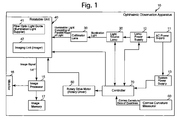
FIG. 1 is a block diagram showing the structure of an embodiment of an ophthalmic observation apparatus according to the present invention; -
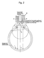
FIG. 2 is a diagram showing a state where the eyeground of the examinee is imaged by an imaging unit in an eyeground observation position where illumination light consisting of substantially parallel rays of light supplied through a fiber optic light guide is substantially parallel to a straight line which passes through the surface center and the curvature center of the cornea of the examinee; -
FIG. 3 is a diagram showing a state where the anterior chamber angle of the examinee is imaged by the imaging unit in one of two anterior chamber observation positions where illumination light consisting of substantially parallel rays of light supplied through the fiber optic light guide is inclined to the aforementioned straight line, which passes through the surface center and the curvature center of the cornea of the examinee; -
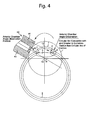
FIG. 4 is a diagram showing a state where the anterior chamber angle of the examinee is imaged by the imaging unit in the other of two anterior-chamber observation positions where illumination light consisting of substantially parallel rays of light supplied through the fiber optic light guide is inclined to the straight line that passes through the surface center and the curvature center of the cornea of the examinee; and -
FIG. 5 is a flow chart showing a method of using the ophthalmic observation apparatus according to the present invention. - An embodiment of an
ophthalmic observation apparatus 10 according to the present invention will be hereinafter discussed with reference toFIGS. 1 through 5 . - As shown in
FIG. 1 , theophthalmic observation apparatus 10 is provided with anAC power supply 11, alamp power supply 12 and asystem power supply 13. TheAC power supply 11 serves as a power supply for all the components of theophthalmic observation apparatus 10, thelamp power supply 12 supplies driving power received from theAC power supply 11 to a lamp system for theophthalmic observation apparatus 10, and thesystem power supply 13 supplies driving power received from theAC power supply 11 to a controller (control system) 70 for theophthalmic observation apparatus 10. - The
ophthalmic observation apparatus 10 is provided with alight source lamp 20 which emits illumination light using driving power supplied from thelamp power supply 12 and acollimator lens 30 which collimates the incident light from thelight source lamp 20. Thelight source lamp 20 is made of, e.g., a halogen lamp, a xenon lamp or an LED lamp. Although not shown in the drawings, a rotating diaphragm plate (rotating chopper) for adjusting the light quantity of illumination light which is emitted by thelight source lamp 20 is installed between thelight source lamp 20 and thecollimator lens 30. - As shown in
FIGS. 1 through 4 , theophthalmic observation apparatus 10 is provided with arotatable unit 40 on which the illumination light emitted from thelight source lamp 20 and collimated by thecollimator lens 30 is incident. Therotatable unit 40 is provided with a cylindrical (ring-shaped) fiber optic light guide (illumination light supplier) 41 and an imaging unit (imager) 42 which is installed in the core of the fiberoptic light guide 41. The fiberoptic light guide 41 supplies illumination light consisting of substantially parallel rays of light and having a ring shape in cross section toward the eye of the examinee. Theimaging unit 42 is a combination of an objective optical system and a solid-state image pickup device and images the examinee's eye (ocular fundus, anterior chamber angle, etc.) which is illuminated by illumination light (consisting of substantially parallel rays of light) supplied through the fiberoptic light guide 41. Namely, the illumination light (consisting of substantially parallel rays of light) which emerges from the front end (the end closest to the examinee) of the fiberoptic light guide 41 illuminates the examinee's eye (ocular fundus, anterior chamber angle, etc.), and the reflected light is imaged and converted into an image signal by theimaging unit 42. This image signal is transmitted to animage processor 15 provided as a component of theophthalmic observation apparatus 10 via an imagesignal transmission cable 14, and a predetermined image processing is performed on the image signal thus transmitted in theimage processor 15. Thereupon, this image signal is visually indicated as an observing image on amonitor 16 which is provided as a component of theophthalmic observation apparatus 10, and the same image signal is stored in animage memory 17 connected to theimage processor 15. - As shown in
FIG. 1 , theophthalmic observation apparatus 10 is provided with a rotary drive motor (rotary driver) 50 which rotates the rotatable unit 40 (the fiberoptic light guide 41 and the imaging unit 42) about a specific point. Although therotary drive motor 50 is illustrated as an external component of therotatable unit 40 in the block diagram ofFIG. 1 of the present embodiment of the ophthalmic observation apparatus, a different embodiment of the ophthalmic observation apparatus in which therotary drive motor 50 is provided as an internal component of therotatable unit 40 is also possible. - As shown in
FIG. 1 , theophthalmic observation apparatus 10 is provided with acornea curvature measurer 60 for measuring the curvature of a cornea 1 (seeFIGS. 2 through 4 ) of the examinee. Thecornea curvature measurer 60 can be configured of, e.g., an autokeratometer which projects light for measurement onto the center of thecornea 1, captures the reflected light by the light receiving surface of a CCD camera and automatically computes the curvature of thecornea 1; however, the configuration of thecornea curvature measurer 60 is flexible so long as thecornea curvature measurer 60 can measure the curvature of thecornea 1 of the examinee. - As shown in
FIG. 1 , theophthalmic observation apparatus 10 is provided with thecontroller 70, which controls operations of the overall components of theophthalmic observation apparatus 10. For instance, thecontroller 70 is connected to thelamp power supply 12 and thelight source lamp 20 to control the ON/OFF operation of thelight source lamp 20 and the light quantity (luminous intensity) of illumination light emitted by thelight source lamp 20. - The
controller 70 captures observing images of aneyeground 2 and ananterior chamber angle 3 of the examinee by controlling operations of the rotatable unit 40 (the fiberoptic light guide 41 and the imaging unit 42) and therotary drive motor 50 based on the curvature of thecornea 1 of the examinee which has been measured by the cornea curvature measurer 60 (seeFIGS. 2 through 4 ). The term "theeyeground 2 of the examinee" denotes the blood vessels, the retina and the optic nerves in the ocular fundus of the examinee, and the term "theanterior chamber angle 3 of the examinee" denotes a point of intersection of thecornea 1 with aniris 4 of the eye. Thereference numeral 5 inFIGS. 2 through 4 designates the crystalline lens of the eye of the examinee. - As shown in
FIGS. 2 through 4 , thecontroller 70 sets acurvature center 1X of thecornea 1 of the examinee as a specified rotational center based on the curvature of thecornea 1 of the examinee measured by thecornea curvature measurer 60, drives therotary drive motor 50 to rotate the rotatable unit 40 (the fiberoptic light guide 41 and the imaging unit 42) about the specifiedrotational center 1X, and controls theimaging unit 42 to capture an image of theeyeground 2 and theanterior chamber angle 3 illuminated by illumination light consisting of substantially parallel rays of light which is supplied through the fiberoptic light guide 41. - More specifically, assuming that the angle of rotation of the
rotatable unit 40 is 0 degrees when illumination light consisting of substantially parallel rays of light, which is supplied through the fiberoptic light guide 41, is substantially parallel to a straight line which passes through asurface center 1Y of thecornea 1 of the examinee and the curvature center (specified rotational center) 1X of thecornea 1 of the examinee (as shown inFIG. 2 ), thecontroller 70 can rotate the rotatable unit 40 (the fiberoptic light guide 41 and the imaging unit 42) by driving therotary drive motor 50 within the range of ±α° relative to the straight line (i.e., the range of 2α° in total) (seeFIGS. 3 and4 ). In the following descriptions, the position of the rotatable unit 40 (the fiberoptic light guide 41 and the imaging unit 42) in which illumination light consisting of substantially parallel rays of light, which is supplied through the fiberoptic light guide 41, is substantially parallel to a straight line which passes through thesurface center 1Y and thecurvature center 1X of thecornea 1 will be referred to as "eyeground observation position" (therotatable unit 40 is in this position inFIG. 2 ), and the position of the rotatable unit 40 (the fiberoptic light guide 41 and the imaging unit 42) in which the rotatable unit 40 (the fiberoptic light guide 41 and the imaging unit 42) has been rotated at an angle of α° from the eyeground observation position toward either side thereof (clockwise or counterclockwise with respect toFIG. 2 ) will be referred to as "anterior chamber angle observation position" (therotatable unit 40 is in this position in each ofFIGS. 3 and4 ). Namely, therotatable unit 40 can selectively be positioned at the two anterior chamber angle observation positions shown inFIGS. 3 and4 , respectively. Thecontroller 70 controls theimaging unit 42 to capture an image of theeyeground 2 when the rotatable unit 40 (the fiberoptic light guide 41 and the imaging unit 42) is in the eyeground observation position (seeFIG. 2 ), whereas thecontroller 70 controls theimaging unit 42 to capture an image of theanterior chamber angle 3 from two different angles when the rotatable unit 40 (the fiberoptic light guide 41 and the imaging unit 42) is in the two anterior chamber angle observation positions, respectively (seeFIGS. 3 and4 ). The angle α° of the rotatable unit 40 (the fiberoptic light guide 41 and the imaging unit 42) can be set within a range of, e.g., -70 to +70 degrees in accordance with various conditions such as the distance from the rotatable unit 40 (the fiberoptic light guide 41 and the imaging unit 42) to the examinee's eye. - A method of using the
ophthalmic observation apparatus 10 that has the above described structure will be hereinafter discussed with reference to the flow chart shown inFIG. 5 . - First, at step S1, the
cornea curvature measurer 60 measures the curvature of thecornea 1 of the examinee and sends data on this measured curvature, as cornea curvature data, to thecontroller 70. - Subsequently, at step S2, based on the curvature of the
cornea 1 of the examinee measured by thecornea curvature measurer 60, thecontroller 70 sets thecurvature center 1X of thecornea 1 of the examinee as a specified rotational center for the rotatable unit 40 (the fiberoptic light guide 41 and the imaging unit 42). - Subsequently, at step S3, the
controller 70 drives therotary drive motor 50 to rotate the rotatable unit 40 (the fiberoptic light guide 41 and the imaging unit 42) about the specified rotational center (thecurvature center 1X) to the eyeground observation position and thereupon controls theimaging unit 42 to capture an image of theeyeground 2 of the examinee in the eyeground observation position (seeFIG. 2 ). - Subsequently, at steps S4 and S5, the
controller 70 drives therotary drive motor 50 to rotate the rotatable unit 40 (the fiberoptic light guide 41 and the imaging unit 42) about the specified rotational center (thecurvature center 1X), firstly, to one of the two anterior chamber angle observation positions to image theanterior chamber angle 3 in this one angle observation position, and secondly, to the other anterior chamber angle observation position to image theanterior chamber angle 3 in the other angle observation position (seeFIGS. 3 and4 ). - The above described operations at steps S3, S4 and S5 do not necessarily have to be performed in that specific order; namely, the order of these operation to be performed can be changed as appropriate.
- Lastly, at step S6, the
image processor 15 performs a predetermined image processing operation on the image signal representing images taken (captured) by theimaging unit 42, thereafter indicates the observing images of theeyeground 2 and theanterior chamber angle 3 of the examinee on themonitor 16, and stores the image signal in theimage memory 17. - The presence or absence of eye diseases such as cataract and glaucoma and conditions of such eye diseases can be made known by a medical doctor(s) observing and examining the observing images of the
eyeground 2 and theanterior chamber angle 3 of the examinee on themonitor 16. For instance, in the case of cataract, characteristics of retinitis pigmentosa (pigmentary degeneration of the retina) can be seen in the observing image of the eyeground, and haze appears in the observing image of theanterior chamber angle 3. Theeyeground 2 contains cone cells (corns) and rod cells (rods), which are sensitive to light, in the retina. Cone cells are responsible for color vision as well as sharpness of vision (eyesight), whereas rod cells are used in peripheral vision and function in less intense light than cone cells, thus being responsible for night vision. In general, it is said that an abnormality appears in cone cells after a disorder of rod cells occurs and that a cataract is caused by a large abnormality in rod cells. - As described above, according to the present embodiment of the
ophthalmic observation apparatus 10, thecontroller 70 sets thecurvature center 1X of thecornea 1 of the examinee as a specified rotational center based on the curvature of thecornea 1 of the examinee measured by thecornea curvature measurer 60, drives therotary drive motor 50 to rotate the rotatable unit 40 (the fiber opticlight guide 41 and the imaging unit 42) about the specifiedrotational center 1X, and controls theimaging unit 42 to capture an image of theeyeground 2 and theanterior chamber angle 3 illuminated by illumination light, consisting of substantially parallel rays of light, which is supplied through the fiber opticlight guide 41. This makes it possible to reduce the size of the examination system and costs, shorten the time required for the examination, and allow ophthalmoscopy and gonioscopy to be performed with precision in a continuous work-flow manner. - More specifically, the eyeground observation position and the two anterior chamber angle observation positions are defined by rotating the rotatable unit 40 (the fiber optic
light guide 41 and the imaging unit 42) so as to swing along a circular arc which is concentric with and greater in radius of curvature than the circular arc of thecornea 1, and images of theeyeground 2 and theanterior chamber angle 3 of the examinee are captured, accordingly, the examination system is small in size and low in cost. Moreover, the time required for the examination is short, and ophthalmoscopy and gonioscopy can be performed with precision in a continuous work-flow manner. In addition, since illumination light supplied toward the examinee's eye is collimated into substantially parallel rays of light to prevent the illumination light from dispersing at the retina of the examinee, and also since thecontroller 70 sets thecurvature center 1X of thecornea 1 of the examinee as a specified rotational center for the rotatable unit 40 (the fiber opticlight guide 41 and the imaging unit 42) based on the curvature of thecornea 1 of the examinee measured by thecornea curvature measurer 60, ophthalmoscopy and gonioscopy can be performed with higher precision. Additionally, since thecurvature center 1X of theretina 1 varies depending on the examinee, safety of the examination using theophthalmic observation apparatus 10 can be secured simply by setting thecurvature center 1X of thecornea 1 of each examinee as a specified rotational center for the rotatable unit 40 (the fiber opticlight guide 41 and the imaging unit 42). In practice, since the illumination light supplied toward the examinee's eye is dispersed in the leftward/rightward direction with respect toFIGS. 2 through 4 due to lens effect of thecrystalline lens 5, theeyeground 2 of the examinee can be widely observed. - Obvious changes may be made in the specific embodiment of the present invention described herein, such modifications being within the spirit and scope of the invention claimed. It is indicated that all matter contained herein is illustrative and does not limit the scope of the present invention.
Claims (5)
- An ophthalmic observation apparatus comprising:an illumination light supplier which supplies illumination light, consisting of substantially parallel rays of light, toward an eye of an examinee which includes an eyeground and an anterior chamber angle;an imager which captures an image of said eye which is illuminated by said illumination light;a rotary driver which rotates said illumination light supplier and said imager about a specified rotational center;a cornea curvature measurer which measures a curvature of a cornea of said eye of said examinee; anda controller which sets a curvature center of said cornea as said specified rotational center based on said curvature of said cornea measured by said cornea curvature measurer,wherein said controller drives said rotary driver to rotate said illumination light supplier and said imager about said specified rotational center and controls said imager to capture an image of said eyeground and said anterior chamber angle illuminated by said illumination light.
- The ophthalmic observation apparatus according to claim 1, wherein said imager captures an image of said eyeground when said illumination light, which is supplied by said illumination light supplier, is substantially parallel to a straight line which passes through a surface center of said cornea and said curvature center of said cornea, and
wherein said imager captures an image of said anterior chamber angle when said illumination light, which is supplied by said illumination light supplier, is inclined to said straight line. - The ophthalmic observation apparatus according to claim 1, wherein said rotary driver rotates said illumination light supplier and said imager about said specified rotational center within a range of -70 to +70 degrees relative to said straight line, wherein a rotation angle of said illumination light supplier and said imager about said specified rotational center is 0 degrees when said illumination light is substantially parallel to a straight line which passes through a surface center of said cornea and said curvature center of said cornea.
- The ophthalmic observation apparatus according to claim 1, further comprising a rotatable unit which includes said illumination light supplier and said imager,
wherein said rotatable unit can be rotatably driven about said specified rotational center by said rotary driver. - A method of using an ophthalmic observation apparatus, which includes an illumination light supplier which supplies, toward an eye of an examinee which includes an eyeground and an anterior chamber angle, illumination light consisting of substantially parallel rays of light, an imager which captures an image of said eye which is illuminated by said illumination light, a rotary driver which rotates said illumination light supplier and said imager about a specified rotational center, and a cornea curvature measurer which measures a curvature of a cornea of said eye of said examinee, said method comprising:setting a curvature center of said cornea as said specified rotational center based on said curvature of said cornea measured by said cornea curvature measurer;controlling said imager to capture an image of said eyeground illuminated by said illumination light when said illumination light supplier and said imager are rotated about said specified rotational center by said rotary driver to an eyeground observation position; andcontrolling said imager to capture an image of said anterior chamber angle illuminated by said illumination light when said illumination light supplier and said imager are rotated about said specified rotational center by said rotary driver to an anterior chamber angle observation position that is different from said eyeground observation position.
Applications Claiming Priority (1)
| Application Number | Priority Date | Filing Date | Title |
|---|---|---|---|
| JP2013081923A JP2014200621A (en) | 2013-04-10 | 2013-04-10 | Ophthalmic observation apparatus and method for using the same |
Publications (2)
| Publication Number | Publication Date |
|---|---|
| EP2789292A2 true EP2789292A2 (en) | 2014-10-15 |
| EP2789292A3 EP2789292A3 (en) | 2014-11-12 |
Family
ID=50440551
Family Applications (1)
| Application Number | Title | Priority Date | Filing Date |
|---|---|---|---|
| EP14163821.3A Withdrawn EP2789292A3 (en) | 2013-04-10 | 2014-04-08 | Ophtalmic observation apparatus and method of using the same |
Country Status (4)
| Country | Link |
|---|---|
| US (1) | US20140307227A1 (en) |
| EP (1) | EP2789292A3 (en) |
| JP (1) | JP2014200621A (en) |
| CN (1) | CN104095612A (en) |
Families Citing this family (5)
| Publication number | Priority date | Publication date | Assignee | Title |
|---|---|---|---|---|
| TW201703722A (en) * | 2015-07-21 | 2017-02-01 | 明達醫學科技股份有限公司 | Measurement apparatus and operating method thereof |
| JP6255470B1 (en) * | 2016-12-27 | 2017-12-27 | 株式会社Qdレーザ | Retina scanning optometry apparatus, retinal scanning optometry system, retinal scanning optometry method, retinal scanning eyewear providing system, retinal scanning eyewear providing method, and retinal scanning eyewear |
| CN107518870B (en) * | 2017-08-28 | 2019-07-26 | 温州医科大学 | An OCT-based angle optical coherence tomography device and imaging method |
| CN108056752A (en) * | 2017-11-24 | 2018-05-22 | 李国增 | A kind of ophthalmology observes device |
| CN108324241B (en) * | 2018-01-22 | 2024-02-02 | 深圳盛达同泽科技有限公司 | Multispectral light source, fundus imaging system and imaging method |
Citations (1)
| Publication number | Priority date | Publication date | Assignee | Title |
|---|---|---|---|---|
| WO2012001381A2 (en) | 2010-07-01 | 2012-01-05 | Optos Plc. | Improvements in or relating to ophthalmology |
Family Cites Families (2)
| Publication number | Priority date | Publication date | Assignee | Title |
|---|---|---|---|---|
| EP1417925A1 (en) * | 2002-11-07 | 2004-05-12 | Haag-Streit Ag | Apparatus for viewing an eye |
| JP5887191B2 (en) * | 2012-04-19 | 2016-03-16 | 株式会社トーメーコーポレーション | Corneal imaging apparatus and cornea imaging method |
-
2013
- 2013-04-10 JP JP2013081923A patent/JP2014200621A/en active Pending
-
2014
- 2014-04-07 US US14/246,453 patent/US20140307227A1/en not_active Abandoned
- 2014-04-08 EP EP14163821.3A patent/EP2789292A3/en not_active Withdrawn
- 2014-04-09 CN CN201410141198.5A patent/CN104095612A/en active Pending
Patent Citations (1)
| Publication number | Priority date | Publication date | Assignee | Title |
|---|---|---|---|---|
| WO2012001381A2 (en) | 2010-07-01 | 2012-01-05 | Optos Plc. | Improvements in or relating to ophthalmology |
Also Published As
| Publication number | Publication date |
|---|---|
| JP2014200621A (en) | 2014-10-27 |
| US20140307227A1 (en) | 2014-10-16 |
| CN104095612A (en) | 2014-10-15 |
| EP2789292A3 (en) | 2014-11-12 |
Similar Documents
| Publication | Publication Date | Title |
|---|---|---|
| JP5451326B2 (en) | Retinographic digital processing device | |
| US8550626B2 (en) | Instrument for eye examination | |
| US10188282B2 (en) | Subjective optometry apparatus | |
| US10039450B2 (en) | Ophthalmologic apparatus | |
| US9782067B2 (en) | Optometric apparatus | |
| US20140307227A1 (en) | Ophthalmic observation apparatus and method of using the same | |
| JP7731480B2 (en) | Ophthalmic device, method for controlling ophthalmic device, and program | |
| US9339185B2 (en) | Imaging apparatus that acquires a first image and, via an aberration correction unit, a second image of an area corresponding to a part of the first image | |
| JP7459491B2 (en) | Ophthalmology measuring device | |
| JP6494385B2 (en) | Optical image pickup apparatus and control method thereof | |
| JP2016168257A (en) | Ophthalmologic apparatus, control method thereof, and program | |
| JP4850561B2 (en) | Ophthalmic equipment | |
| JP2020151094A (en) | Ophthalmic equipment | |
| JP7283391B2 (en) | eye refractive power measuring device | |
| JP2013248075A (en) | Fundus examination apparatus | |
| CN208610810U (en) | A kind of Fundus Camera System for eye examination | |
| JP2020179175A (en) | Ophthalmic equipment | |
| JP2016106962A (en) | Ophthalmologic apparatus and control method thereof | |
| KR100796355B1 (en) | Slit lamp inspection device using near infrared | |
| RU2466674C2 (en) | Universal composite ophthalmic diagnostic system | |
| US12551102B2 (en) | Systems and methods for peripheral retinal optical coherence tomography | |
| KR20140112615A (en) | Optical coherence tomography device having mire ring light source | |
| US11344197B2 (en) | Digital 3D infrared slit lamp with pupil and retina intensity measurement | |
| CN111542257A (en) | Ophthalmic composite optical image capturing apparatus and control method thereof | |
| EP4670618A1 (en) | OPHTHALMIC DEVICE AND METHOD FOR OPERATING AN OPHTHALMIC DEVICE |
Legal Events
| Date | Code | Title | Description |
|---|---|---|---|
| PUAL | Search report despatched |
Free format text: ORIGINAL CODE: 0009013 |
|
| PUAI | Public reference made under article 153(3) epc to a published international application that has entered the european phase |
Free format text: ORIGINAL CODE: 0009012 |
|
| 17P | Request for examination filed |
Effective date: 20140408 |
|
| AK | Designated contracting states |
Kind code of ref document: A2 Designated state(s): AL AT BE BG CH CY CZ DE DK EE ES FI FR GB GR HR HU IE IS IT LI LT LU LV MC MK MT NL NO PL PT RO RS SE SI SK SM TR |
|
| AX | Request for extension of the european patent |
Extension state: BA ME |
|
| AK | Designated contracting states |
Kind code of ref document: A3 Designated state(s): AL AT BE BG CH CY CZ DE DK EE ES FI FR GB GR HR HU IE IS IT LI LT LU LV MC MK MT NL NO PL PT RO RS SE SI SK SM TR |
|
| AX | Request for extension of the european patent |
Extension state: BA ME |
|
| RIC1 | Information provided on ipc code assigned before grant |
Ipc: A61B 3/117 20060101AFI20141006BHEP Ipc: A61B 3/18 20060101ALI20141006BHEP Ipc: A61B 3/107 20060101ALN20141006BHEP Ipc: A61B 3/12 20060101ALI20141006BHEP Ipc: A61B 3/14 20060101ALI20141006BHEP |
|
| STAA | Information on the status of an ep patent application or granted ep patent |
Free format text: STATUS: THE APPLICATION HAS BEEN WITHDRAWN |
|
| 18W | Application withdrawn |
Effective date: 20150319 |