EP2787562A1 - Rechargeable secondary battery - Google Patents
Rechargeable secondary battery Download PDFInfo
- Publication number
- EP2787562A1 EP2787562A1 EP20130187732 EP13187732A EP2787562A1 EP 2787562 A1 EP2787562 A1 EP 2787562A1 EP 20130187732 EP20130187732 EP 20130187732 EP 13187732 A EP13187732 A EP 13187732A EP 2787562 A1 EP2787562 A1 EP 2787562A1
- Authority
- EP
- European Patent Office
- Prior art keywords
- region
- elastic force
- collector plate
- secondary battery
- fuse
- Prior art date
- Legal status (The legal status is an assumption and is not a legal conclusion. Google has not performed a legal analysis and makes no representation as to the accuracy of the status listed.)
- Granted
Links
Images




Classifications
-
- H—ELECTRICITY
- H01—ELECTRIC ELEMENTS
- H01M—PROCESSES OR MEANS, e.g. BATTERIES, FOR THE DIRECT CONVERSION OF CHEMICAL ENERGY INTO ELECTRICAL ENERGY
- H01M50/00—Constructional details or processes of manufacture of the non-active parts of electrochemical cells other than fuel cells, e.g. hybrid cells
- H01M50/50—Current conducting connections for cells or batteries
- H01M50/572—Means for preventing undesired use or discharge
- H01M50/574—Devices or arrangements for the interruption of current
- H01M50/581—Devices or arrangements for the interruption of current in response to temperature
-
- H—ELECTRICITY
- H01—ELECTRIC ELEMENTS
- H01M—PROCESSES OR MEANS, e.g. BATTERIES, FOR THE DIRECT CONVERSION OF CHEMICAL ENERGY INTO ELECTRICAL ENERGY
- H01M10/00—Secondary cells; Manufacture thereof
- H01M10/04—Construction or manufacture in general
- H01M10/0431—Cells with wound or folded electrodes
-
- H—ELECTRICITY
- H01—ELECTRIC ELEMENTS
- H01M—PROCESSES OR MEANS, e.g. BATTERIES, FOR THE DIRECT CONVERSION OF CHEMICAL ENERGY INTO ELECTRICAL ENERGY
- H01M4/00—Electrodes
- H01M4/02—Electrodes composed of, or comprising, active material
- H01M4/64—Carriers or collectors
- H01M4/70—Carriers or collectors characterised by shape or form
-
- H—ELECTRICITY
- H01—ELECTRIC ELEMENTS
- H01M—PROCESSES OR MEANS, e.g. BATTERIES, FOR THE DIRECT CONVERSION OF CHEMICAL ENERGY INTO ELECTRICAL ENERGY
- H01M50/00—Constructional details or processes of manufacture of the non-active parts of electrochemical cells other than fuel cells, e.g. hybrid cells
- H01M50/10—Primary casings; Jackets or wrappings
- H01M50/172—Arrangements of electric connectors penetrating the casing
- H01M50/174—Arrangements of electric connectors penetrating the casing adapted for the shape of the cells
- H01M50/176—Arrangements of electric connectors penetrating the casing adapted for the shape of the cells for prismatic or rectangular cells
-
- H—ELECTRICITY
- H01—ELECTRIC ELEMENTS
- H01M—PROCESSES OR MEANS, e.g. BATTERIES, FOR THE DIRECT CONVERSION OF CHEMICAL ENERGY INTO ELECTRICAL ENERGY
- H01M50/00—Constructional details or processes of manufacture of the non-active parts of electrochemical cells other than fuel cells, e.g. hybrid cells
- H01M50/20—Mountings; Secondary casings or frames; Racks, modules or packs; Suspension devices; Shock absorbers; Transport or carrying devices; Holders
-
- H—ELECTRICITY
- H01—ELECTRIC ELEMENTS
- H01M—PROCESSES OR MEANS, e.g. BATTERIES, FOR THE DIRECT CONVERSION OF CHEMICAL ENERGY INTO ELECTRICAL ENERGY
- H01M50/00—Constructional details or processes of manufacture of the non-active parts of electrochemical cells other than fuel cells, e.g. hybrid cells
- H01M50/50—Current conducting connections for cells or batteries
- H01M50/531—Electrode connections inside a battery casing
- H01M50/533—Electrode connections inside a battery casing characterised by the shape of the leads or tabs
-
- H—ELECTRICITY
- H01—ELECTRIC ELEMENTS
- H01M—PROCESSES OR MEANS, e.g. BATTERIES, FOR THE DIRECT CONVERSION OF CHEMICAL ENERGY INTO ELECTRICAL ENERGY
- H01M50/00—Constructional details or processes of manufacture of the non-active parts of electrochemical cells other than fuel cells, e.g. hybrid cells
- H01M50/50—Current conducting connections for cells or batteries
- H01M50/531—Electrode connections inside a battery casing
- H01M50/538—Connection of several leads or tabs of wound or folded electrode stacks
-
- H—ELECTRICITY
- H01—ELECTRIC ELEMENTS
- H01M—PROCESSES OR MEANS, e.g. BATTERIES, FOR THE DIRECT CONVERSION OF CHEMICAL ENERGY INTO ELECTRICAL ENERGY
- H01M50/00—Constructional details or processes of manufacture of the non-active parts of electrochemical cells other than fuel cells, e.g. hybrid cells
- H01M50/50—Current conducting connections for cells or batteries
- H01M50/572—Means for preventing undesired use or discharge
- H01M50/574—Devices or arrangements for the interruption of current
- H01M50/583—Devices or arrangements for the interruption of current in response to current, e.g. fuses
-
- H—ELECTRICITY
- H01—ELECTRIC ELEMENTS
- H01M—PROCESSES OR MEANS, e.g. BATTERIES, FOR THE DIRECT CONVERSION OF CHEMICAL ENERGY INTO ELECTRICAL ENERGY
- H01M50/00—Constructional details or processes of manufacture of the non-active parts of electrochemical cells other than fuel cells, e.g. hybrid cells
- H01M50/50—Current conducting connections for cells or batteries
- H01M50/572—Means for preventing undesired use or discharge
- H01M50/584—Means for preventing undesired use or discharge for preventing incorrect connections inside or outside the batteries
- H01M50/586—Means for preventing undesired use or discharge for preventing incorrect connections inside or outside the batteries inside the batteries, e.g. incorrect connections of electrodes
-
- H—ELECTRICITY
- H01—ELECTRIC ELEMENTS
- H01M—PROCESSES OR MEANS, e.g. BATTERIES, FOR THE DIRECT CONVERSION OF CHEMICAL ENERGY INTO ELECTRICAL ENERGY
- H01M50/00—Constructional details or processes of manufacture of the non-active parts of electrochemical cells other than fuel cells, e.g. hybrid cells
- H01M50/50—Current conducting connections for cells or batteries
- H01M50/572—Means for preventing undesired use or discharge
- H01M50/584—Means for preventing undesired use or discharge for preventing incorrect connections inside or outside the batteries
- H01M50/59—Means for preventing undesired use or discharge for preventing incorrect connections inside or outside the batteries characterised by the protection means
- H01M50/593—Spacers; Insulating plates
-
- H—ELECTRICITY
- H01—ELECTRIC ELEMENTS
- H01M—PROCESSES OR MEANS, e.g. BATTERIES, FOR THE DIRECT CONVERSION OF CHEMICAL ENERGY INTO ELECTRICAL ENERGY
- H01M2200/00—Safety devices for primary or secondary batteries
- H01M2200/10—Temperature sensitive devices
- H01M2200/103—Fuse
-
- Y—GENERAL TAGGING OF NEW TECHNOLOGICAL DEVELOPMENTS; GENERAL TAGGING OF CROSS-SECTIONAL TECHNOLOGIES SPANNING OVER SEVERAL SECTIONS OF THE IPC; TECHNICAL SUBJECTS COVERED BY FORMER USPC CROSS-REFERENCE ART COLLECTIONS [XRACs] AND DIGESTS
- Y02—TECHNOLOGIES OR APPLICATIONS FOR MITIGATION OR ADAPTATION AGAINST CLIMATE CHANGE
- Y02E—REDUCTION OF GREENHOUSE GAS [GHG] EMISSIONS, RELATED TO ENERGY GENERATION, TRANSMISSION OR DISTRIBUTION
- Y02E60/00—Enabling technologies; Technologies with a potential or indirect contribution to GHG emissions mitigation
- Y02E60/10—Energy storage using batteries
-
- Y—GENERAL TAGGING OF NEW TECHNOLOGICAL DEVELOPMENTS; GENERAL TAGGING OF CROSS-SECTIONAL TECHNOLOGIES SPANNING OVER SEVERAL SECTIONS OF THE IPC; TECHNICAL SUBJECTS COVERED BY FORMER USPC CROSS-REFERENCE ART COLLECTIONS [XRACs] AND DIGESTS
- Y02—TECHNOLOGIES OR APPLICATIONS FOR MITIGATION OR ADAPTATION AGAINST CLIMATE CHANGE
- Y02P—CLIMATE CHANGE MITIGATION TECHNOLOGIES IN THE PRODUCTION OR PROCESSING OF GOODS
- Y02P70/00—Climate change mitigation technologies in the production process for final industrial or consumer products
- Y02P70/50—Manufacturing or production processes characterised by the final manufactured product
Definitions
- the present invention relates to a rechargeable secondary battery.
- a rechargeable lithium ion secondary battery may be used, for example, in a small-sized electronic device, such as a notebook computer or a cellular phone. Also, because recently developed rechargeable lithium ion secondary batteries have advantageous characteristics, including high output power, high capacity, and lightness in weight, as compared to other types of rechargeable secondary batteries, they are widely used in hybrid vehicles or electric vehicles.
- a safety device for protecting against external short-circuit or over-charge is provided in the rechargeable lithium ion secondary battery.
- the safety device may cut off a charge or discharge path when the external short-circuit or over-charge occurs to the rechargeable lithium ion secondary battery.
- a secondary battery includes: a case; an electrode assembly in the case via a terminal surface of the case; a collector plate coupled to the electrode assembly and comprising a fuse part; a terminal coupled to the collector plate and extending to an outside of the case; and an elastic force offering part between the case and the collector plate.
- a cross-sectional area of the fuse part may be smaller than a cross-sectional area of another region of the collector plate.
- the elastic force offering part may be configured to exert an elastic force on the fuse part.
- the elastic force offering part may be in a compressed state.
- the elastic force offering part may contact the collector plate at a location adjacent the fuse part.
- the elastic force offering part may be configured to exert a force between the case and the collector plate in a direction that is substantially normal to a plane on which the fuse part is located.
- the collector plate may further include: a first region coupled to the terminal; a second region extending from the first region and coupled to the electrode assembly; and a bent region between the first region and the second region, and the fuse part may be in the second region of the collector plate.
- the collector plate may further include: a first region coupled to the terminal; a second region extending from the first region and coupled to the electrode assembly, and a bent region between the first region and the second region, and the fuse part may be in the first region of the collector plate.
- a cross-sectional area of the fuse part may be smaller than a cross-sectional area of another region of the collector plate.
- the fuse part may be defined by a fuse opening or a notch in the collector plate.
- the fuse part may include a first portion at a first end of the fuse opening and a second portion at a second end of the fuse opening opposite the first end, and a width of each of the first portion and the second portion may be smaller than a width of each of the first region and the second region.
- the elastic force offering part may be configured to separate the first region of the collector plate from the second region of the collector plate when the fuse part is fused.
- the case may include a cap plate between the collector plate and the terminal, and the elastic force offering part may be between the collector plate and the cap plate.
- the secondary battery may further include an insulation part covering the first region of the collector plate and between the collector plate and the cap plate, the collector plate may further include a first protrusion in the first region, the insulation part may include a second protrusion, and the elastic force offering part may be coupled between the first protrusion and the second protrusion.
- the elastic force offering part may be configured to separate the first region of the collector plate from the second region of the collector plate when the fuse part is fused.
- the first protrusion may extend substantially parallel to a side surface of the collector plate, and the second protrusion may extend substantially parallel to a side surface of the insulation part.
- the secondary battery may further include an insulation part covering the first region of the collector plate and between the collector plate and the cap plate, the elastic force offering part may be between the collector plate and the insulation part.
- the elastic force offering part may include a spring selected from the group consisting of a leaf spring, a coil spring, a volute spring, a ring spring, a spiral spring, a disc spring, a washer spring, a rubber spring, a fluid spring, an omega shaped spring, and a resin spring.
- a spring selected from the group consisting of a leaf spring, a coil spring, a volute spring, a ring spring, a spiral spring, a disc spring, a washer spring, a rubber spring, a fluid spring, an omega shaped spring, and a resin spring.
- the elastic force offering part may be generally "W" shaped.
- At least two portions of the elastic force operating part may contact the collector plate, and at least two other portions of the elastic force operating part may contact an insulation part that is between the collector plate and the case.
- the electrode assembly may be at least partially suspended by the collector plate.
- the secondary battery may further include: a second collector plate coupled to the electrode assembly and including a second fuse part; a second terminal coupled to the second collector plate and extending to the outside of the case; and a second elastic force offering part configured to exert an elastic force on the second fuse part.
- the elastic force offering part may be configured to exert a force between the case and the collector plate.
- a secondary battery includes: a case; an electrode assembly in the case; a collector plate coupled to the electrode assembly and having a notch; a terminal coupled to the collector plate and extending to an outside of the case; and an elastic force offering part between the case and the collector plate and contacts the collector plate at a location adjacent the notch.
- a secondary battery includes: a case; an electrode assembly in the case; a collector plate coupled to the electrode assembly and having an opening therein; a terminal coupled to the collector plate and extending to an outside of the case; and an elastic force offering part in the opening in a compressed state.
- FIG. 1a is a perspective view of a rechargeable secondary battery according to an embodiment of the present invention.
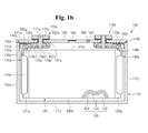
- FIG. 1b is a cross-sectional view taken along the line 1b-1b of FIG. 1a ;
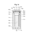
- FIG. 1c is a cross-sectional view taken along the line 1c-1c of FIG. 1a ;
- FIG. 1d is a partial perspective view of a collector plate and surrounding structure of a rechargeable secondary battery according to an embodiment of the present invention
- FIG. 1e is a partial projected view illustrating an elastic force offering part and surrounding structure of a rechargeable secondary battery according to an embodiment of the present invention
- FIGS. 2a and 2b are partial enlarged sectional views illustrating an elastic force offering part and surrounding structure of a rechargeable secondary battery according to an embodiment of the present invention
- FIGS. 3 to 5 are partial enlarged sectional views illustrating an elastic force offering part and surrounding structure of a rechargeable secondary battery according to an embodiment of the present invention
- FIGS. 6a and 6b are partial enlarged sectional views illustrating operating states of a fuse part and an elastic force offering part in the rechargeable secondary battery according to an embodiment of the present invention
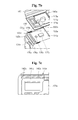
- FIG. 7a is a partial perspective view illustrating a collector plate and an elastic force offering part of a rechargeable secondary battery according to an embodiment of the present invention
- FIG. 7b is a partial exploded view illustrating a collector plate and an elastic force offering part of a rechargeable secondary battery according to an embodiment of the present invention
- FIG. 7c is a bottom view illustrating a portion of a lower insulation part where the elastic force offering part is positioned according to an embodiment of the present invention
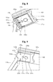
- FIG. 8 is a partial enlarged sectional view illustrating operating states of a fuse part and an elastic force offering part in a rechargeable secondary battery according to an embodiment of the present invention
- FIG. 9 is a partial perspective view illustrating a collector plate and surrounding structure of a rechargeable secondary battery according to an embodiment of the present invention.
- FIG. 10 is a partial enlarged sectional view illustrating an elastic force offering part and surrounding structure of a rechargeable secondary battery according to an embodiment of the present invention.
- FIG. 11 is a partial exploded view illustrating a collector plate and an elastic force offering part of a rechargeable secondary battery according to an embodiment of the present invention.
- first the terms “first,” “second,” etc. may be used herein to describe various members, elements, regions, layers and/or parts, these members, elements, regions, layers and/or parts should not be limited by these terms. These terms are only used to distinguish one member, element, region, layer and/or part from another member, element, region, layer and/or part. Thus, for example, a first member, element, region, layer and/or part discussed below could be termed a second member, element, region, layer and/or part without departing from the spirit and scope of the present invention.
- fuse part when used in this specification, means a region of the collector plate having a relatively small cross-sectional area.
- fuse part is a concept encompassing a fuse hole, fuse opening, or fuse notch for reducing a cross-sectional area.
- elastic force offering part when used in this specification, means all metal or non-metal members that offer an elastic force, that is, all members that can offer an elastic force for rapidly cutting a fuse part when the fuse part is fused.
- FIG. 1a is a perspective view of a rechargeable secondary battery according to an embodiment of the present invention
- FIG. 1b is a cross-sectional view taken along the line 1b-1b of FIG. 1a
- FIG. 1c is a cross-sectional view taken along the line 1c-1c of FIG. 1a
- FIG. 1d is a partial perspective view illustrating a collector plate and surrounding structure of a rechargeable secondary battery according to an embodiment of the present invention
- FIG. 1e is a partial projection view illustrating an elastic force offering part and surrounding structure of a rechargeable secondary battery according to an embodiment of the present invention.
- the rechargeable secondary battery 100 includes a case 110, an electrode assembly 120, a first collector plate 130a, a first insulation part 140a, a first elastic force offering part 150a, a second collector plate 130b, a second insulation part 140b, a second elastic force offering part 150b, a cap plate 160, a first terminal 170a, and a second terminal 170b.
- the case 110 may refer to a can, and/or may encompass the cap plate 160.
- the case 110 includes a pair of long side walls 111a and 111b that are substantially planar and face each other, a pair of short side walls 112a and 112b that connect the long side walls 111a and 111b and face each other, and a bottom wall 113 connecting the long side walls 111a and 111b to the short side walls 112a and 112b.
- areas of the long side walls are larger than those of the short side walls.
- the case 110 may have an open top area sealed with the cap plate 160.
- the electrode assembly 120 and an electrolyte solution are accommodated in the case 110.
- the case 110 may be made of one material selected from the group consisting of aluminum, an aluminum alloy, copper, a copper alloy, iron, an iron alloy, stainless steel and equivalents thereof, but aspects of the present invention are not limited thereto.
- the electrode assembly 120 may include a pair of long side areas 120a and 120b that are substantially planar and face each other, and a pair of short side areas 120c and 120d that connect the long side areas 120a and 120b and face each other.
- the long side areas are wider than the short side areas.
- a first non-coating portion 121a that is not coated with a first active material (not shown) and a second non-coating portion 122a that is not coated with a second active material (not shown) extend (e.g., extend a predetermined length) in opposite directions.
- the first non-coating portion 121a may extend and protrude to one side a predetermined length through the long side areas 120a and 120b and the short side areas 120c and 120d
- the second non-coating portion 122a may extend and protrude to the other side a predetermined length through the long side areas 120a and 120b and the short side areas 120c and 120d
- the first non-coating portion 121a and the second non-coating portion 122a of the electrode assembly 120 may extend a predetermined length toward the short side walls 112a and 112b provided in the case 110, respectively.
- the electrode assembly 120 may be formed by winding or laminating a stacked structure having a first electrode plate 121, a second electrode plate 122, and a separator 123 interposed between the first and second electrode plates 121 and 122, which are formed of a thin plate or layer.
- the first electrode plate 121 may function as a positive electrode and the second electrode plate 122 may function as a negative electrode, or vice versa.
- the first electrode plate 121 may be formed by applying a first electrode active material, such as a transition metal, on a first electrode collector plate (not shown) formed of, for example, aluminum foil.
- the first electrode plate 121 may include a first non-coating portion 121a on which the first electrode active metal is not applied.
- the first non-coating portion 121a may function as a passage for current flowing between the first electrode plate 121 and the outside of the first electrode plate 121.
- the present invention does not limit the material of the first electrode plate 121 to those listed herein.
- the second electrode plate 122 may be formed by applying a second electrode active material, such as graphite or carbon, on a second electrode collector plate (not shown) formed of metal foil, such as copper, a copper alloy or nickel.
- the second electrode plate 122 may include a second non-coating portion 122a on which the second electrode active metal is not applied.
- the second non-coating portion 122a may function as a passage for current flowing between the second electrode plate 122 and the outside of the second electrode plate 122.
- the present invention does not limit the material of the second electrode plate 122 to those listed herein. In other embodiments, the relative polarities of the first and second electrode plates 121 and 122 may differ from what is described above.
- the separator 123 may be between the first electrode plate 121 and the second electrode plate 122 to prevent short circuiting and allow movement of lithium ions.
- the separator 123 may be formed of, for example, polyethylene, polypropylene, or combined film of polypropylene and polyethylene. The present invention does not limit the material of the separator 123 to those listed herein.
- the electrode assembly 120 and an electrolyte solution are accommodated within the case 110.
- the electrolyte solution may include an organic solvent, such as ethylene carbonate (EC), propylene carbonate (PC), diethyl carbonate (DEC), ethyl methyl carbonate (EMC), or dimethyl carbonate (DMC), and a lithium salt, such as LiPF 6 or LiBF 4 .
- the electrolyte may be a liquid, a solid, or a gel.
- the first collector plate 130a is positioned inside the case 110 and is electrically connected between the first terminal 170a and the electrode assembly 120.
- the first collector plate 130a includes a first region 131a electrically connected to the first terminal 170a, a second region 132a bent from the first region 131a and electrically connected to the first non-coating portion 121a of the electrode assembly 120, and a bent region 133a between the first region 131a and the second region 132a.
- a third region 134a which may be welded to the first non-coating portion 121a, may be connected to the second region 132a.
- the electrode assembly 120 is constructed such that it is substantially suspended from the first collector plate 130a. That is to say, the electrode assembly 120 may pull down on the first collector plate 130a due to gravity.
- a bottom portion of the electrode assembly 120 is spaced a suitable (or predetermined) distance apart from the bottom wall 113 of the case 110.
- a fuse opening (or hole) 135a is in the first region 131a of the first collector plate 130a.
- the fuse opening 135a may have a substantially rectangular shape.
- a pair of fuse parts 136a, having relatively small cross-sectional areas, may be at opposite sides of the fuse opening 135a.
- widths of the fuse parts 136a may be smaller than a width of the first region 131a or the second region 132a.
- through-holes are shown in the first region 131a to form the fuse parts 136a; however, cut portions may also be in the first region 131a to form the fuse parts 136a.
- the fuse parts 136a may be fused by heat generated when an external short-circuit or over-charge occurs to the rechargeable secondary battery 100, thereby blocking a charge and/or discharge current. Accordingly, the safety of the rechargeable secondary battery 100 is improved.
- coupling openings (or holes) 137a and 138a may be in the first region 131a of the first collector plate 130a to be coupled to a fastening region 171a of the first terminal 170a and a coupling protrusion 174a.
- the first collector plate 130a may include aluminum, an aluminum alloy, titanium, stainless steel, gold, tantalum, niobium, hafnium, zirconium, vanadium, indium, cobalt, tungsten, tin, beryllium, molybdenum, and alloys thereof.
- the present invention does not limit the material of the first collector plate 130a to those listed herein.
- the fuse parts 136a are also made of aluminum.
- the melting point of aluminum is approximately 659°C.
- the fuse parts 136a reach a temperature of approximately 659°C due to an overcurrent, the fuse parts 136a melt and break.
- an arc discharge time is also prolonged, thereby making the rechargeable secondary battery 100 internally unstable.
- the first insulation part 140a may be constructed such that it substantially surrounds the first region 131a of the first collector plate 130a.
- the first insulation part 140a may be positioned between the cap plate 160 and the first region 131a of the first collector plate 130a, and may surround the fastening region 171a of the first terminal 170a, a flange 173a, and the first region 131a of the first collector plate 130a.
- the first insulation part 140a may include an upper region 141a and approximately four side regions 142a.
- the upper region 141a may be interposed between the first region 131a of the first collector plate 130a and the flange 173a of the first terminal 170a, and the cap plate 160.
- the four side regions 142a may surround the first region 131a of the first collector plate 130a, the fastening region 171a of the first terminal 170a, and the side region of the flange 173a.
- the first insulation part 140a may be made of, for example, polyphenylene sulfide (PPS) (which does not react with the electrolyte solution) and equivalents thereof, but the present invention does not limit the material of the first insulation part 140a to those listed herein.
- PPS polyphenylene sulfide
- the first elastic force offering part 150a is between the first collector plate 130a and the cap plate 160.
- the first elastic force offering part 150a may be between the first region 131a of the first collector plate 130a and the first insulation part 140a.
- the first elastic force offering part 150a may be between the fuse parts 136a of the first region 131a (or regions around the fuse parts 136a) and the upper region 141a of the first insulation part 140a.
- the first elastic force offering part 150a is between the bent region 133a (which is between the first region 131a and the second region 132a) and the upper region 141a of the first insulation part 140a.
- the first elastic force offering part 150a may be maintained in a compressed state between the bent region 133a of the first collector plate 130a and the upper region 141a of the first insulation part 140a.
- the first elastic force offering part 150a may be maintained at a compressed state so as to downwardly push the fuse parts 136a, the regions adjacent to the fuse parts 136a, the bent region 133a, ends of the first region 131a, and/or ends of the second region 132a from the cap plate 160 or the first insulation part 140a.
- the first elastic force offering part 150a may have various shapes.
- the first elastic force offering part 150a may be substantially "W" shaped.
- a region of the first elastic force offering part 150a may contact the upper region 141a of the first insulation part 140a, and another portion of the first elastic force offering part 150a may contact the fuse parts 136a, the regions adjacent to the fuse parts 136a, the bent region 133a, the ends of the first region 131a, and/or the ends of the second region 132a, or vice versa.
- the fuse parts 136a are capable of being rapidly broken by the fusion thereof and a force (e.g., an elastic force) provided by (or derived from) the elastic force offering part 150a when an overcurrent flows through the rechargeable secondary battery 100 due to, for example, an external short circuit or overcharge. Accordingly, during an external short circuit or overcharge of the rechargeable secondary battery 100, charge and/or discharge paths are rapidly cut off.
- a force e.g., an elastic force
- an arc discharge may occur when fuse parts are fused.
- Arc discharges may affect electrolyte solutions, which may result in rapidly increasing the internal pressure of a rechargeable secondary battery.
- an arc discharge time is reduced (or minimized). Therefore, internal pressure increasing due to arc discharges may be prevented (or suppressed).
- fuse parts 136a of embodiments of the present invention are cut off by the elastic force provided by the elastic force offering part 150a.
- fuse parts may reconnect.
- the first region 131a and the second region 132a are separated away from each other by the elastic force of the elastic force offering part 150a, thereby preventing the fuse parts 136a from being reconnected.
- the first elastic force offering part 150a may be one selected from the group consisting of a leaf spring, a coil spring, a volute spring, a ring spring, a spiral spring, a disc spring, a washer spring, an omega shaped spring, and equivalents thereof, but aspects of the present invention are not limited thereto.
- the first elastic force offering part 150a may include metal or non-metal materials.
- a steel spring e.g., carbon steel spring, an alloy steel spring, etc.
- a non-ferrous spring e.g., a copper alloy spring, a nickel alloy spring, etc.
- a rubber spring, a fluid spring (e.g., an air spring, a liquid spring, etc.) or a synthetic resin spring (e.g., a laminate spring, etc.) may be used as the non-metal material.
- the cap plate 160 may cover an open portion of the case 110 while being exposed to or to protrude to the outside of the first terminal 170a. A boundary between the case 110 and the cap plate 160 may be welded by laser beam.
- an electrolyte injection opening (or hole) 161 may be in the cap plate 160.
- the electrolyte injection opening 161 may be closed by a plug 162, and a safety vent 163 having a relatively small thickness may also be in the cap plate 160.
- the cap plate 160 may be made of a substantially the same material as the case 110.
- the first terminal 170a is electrically connected to the first collector plate 130a and outwardly extends a suitable (or a predetermined) length while passing through the cap plate 160.
- the first terminal 170a is coupled to the first region 131a of the first collector plate 130a and outwardly extends a suitable (or a predetermined) length while passing through the first insulation part 140a and the cap plate 160.
- the first terminal 170a may be electrically and mechanically coupled to the coupling opening 137a provided in the first region 131a of the first collector plate 130a.
- the first terminal 170a may include a pillar-shaped fastening region 171a, and a fixing region 172a fixed to the case 110 or the fastening region 171a outside the cap plate 160 and having a bus bar (not shown) coupled thereto.
- a leaf-shaped flange 173a horizontally extending a suitable (or a predetermined) length may be inside the case 110 or in the cap plate 160 in the fastening region 171a.
- the flange 173a may include a coupling protrusion 174a coupled to the coupling opening 138a downwardly extending and provided in the first region 131a of the first collector plate 130a.
- a top surface of the flange 173a may make close contact with the upper region 141a of the first insulation part 140a.
- a suitable (or predetermined) space may be between the flange 173a and the side region 142a of the first insulation part 140a, and the first elastic force offering part 150a may be positioned in this space.
- the fuse parts 136a and the bent region 133a of the first collector plate 130a may also be in this space.
- the fastening region 171a, the fixing region 172a, the flange 173a, and the coupling protrusion 174a, forming the first terminal 170a may include one selected from the group consisting of aluminum, an aluminum alloy, and equivalents thereof, but the present invention does not limit the materials of the fastening region 171a, the fixing region 172a, the flange 173a and the coupling protrusion 174a.
- the fastening region 171a positioned on the cap plate 160 may be coupled to the fixing region 172a to be riveted or welded, and the fastening region 171a and the coupling protrusion 174a positioned under the cap plate 160 may be coupled to the coupling openings 137a and 138a provided in the first region 131a of the first collector plate 130a to be riveted or welded.
- the fastening region 171a of the first terminal 170a may pass through the cap plate 160, and a seal gasket 181a may be on the outer circumference. Therefore, the first terminal 170a may be insulated from the cap plate 160.
- the seal gasket 181a may be made of polyphenylene sulfide (PPS) (which does not react with the electrolyte solution), but the present invention does not limit the material of the seal gasket 181a to those listed herein.
- An upper insulation part 182a may be provided between the fixing region 172a and the case 110.
- the upper insulation part 182a may make close contact with the seal gasket 181a.
- the upper insulation part 182a insulates the first fixing region 172a from the cap plate 160.
- the upper insulation part 182a may be made of polyphenylene sulfide (PPS), but the present invention does not limit the material of the upper insulation part 182a to those listed herein.
- the fixing region 172a and the cap plate 160 may be electrically connected to each other by a high-resistance member (not shown).
- the second collector plate 130b, the second insulation part 140b, the second elastic force offering part 150b, and the second terminal 170b may be substantially the same as the first collector plate 130a, the first insulation part 140a, the first elastic force offering part 150a, and the first terminal 170a.
- a fuse opening (or hole) 135b and a fuse part 136b may be provided in the second collector plate 130b.
- the fuse opening 135b and the fuse part 136b may not be provided in the second collector plate 130b, and the second elastic force offering part 150b may not be provided at the second collector plate 130b.
- the second collector plate 130b may be made of copper or a copper alloy, and a melting point of copper is approximately 1,083°C, which is higher than that of aluminum.
- the fuse parts 136a of the first collector plate 130a may first operate, so that charge current and/or discharge current are cut off.
- the fuse opening 135b and the fuse part 136b of the second collector plate 130b and the second elastic force offering part 150b may be installed.
- the first collector plate 130a and the second collector plate 130b, the first insulation part 140a and the second insulation part 140b, and the first elastic force offering part 150a and the second elastic force offering part 150b may have substantially the same configurations, respectively. Therefore, the present invention will be described below by generally designating the respective components as the current collector plate 130a, the insulation part 140a and the elastic force offering part 150a.
- FIGS. 2a and 2b are partial enlarged sectional views illustrating an elastic force offering part and surrounding structure of a rechargeable secondary battery according to an embodiment of the present invention.
- the elastic force offering part 150a is on the ends of the first region 131a or the ends of the second region 132a in the current collector plate 130a, the fuse parts 136a, the regions adjacent to the fuse parts 136a, or the bent region 133a.
- the upper region 141a of the insulation part 140a may be on the elastic force offering part 150a.
- the elastic force offering part 150a is substantially "W" shaped. At least two regions of the elastic force offering part 150a contacts the current collector plate 130a, and at least two other regions of the elastic force offering part 150a contacts the upper region 141a or the side regions 142a of the insulation part 140a.
- the elastic force offering part 150a is maintained at a compressed state between the collector plate 130a and the insulation part 140a. Therefore, when the fuse parts 136a are fused, the elastic force offering part 150a allows the second region 132a of the current collector plate 130a to rapidly move downwards.
- FIGS. 3 to 5 are partial enlarged sectional views illustrating an elastic force offering part and surrounding structure of a rechargeable secondary battery according to embodiments of the present invention.
- At least three regions of an elastic force offering part 250a contact ends of a first region 131a or ends of a second region 132a of a current collector plate 130a, fuse parts 136a, regions adjacent to the fuse parts 136a, or a bent region 133a.
- the elastic force offering part 250a may contact at least two regions of an upper region 141a or side regions 142a of an insulation part 140a.
- At least three regions of the elastic force offering part 250a push (e.g., downwardly push) the ends of the first region 131a, the ends of the second region 132a, the fuse parts 136a, the regions adjacent to the fuse parts 136a, or the bent region 133a.
- At least one region of an elastic force offering part 350a contacts ends of a first region 131a or ends of a second region 132a of a current collector plate 130a, fuse parts 136a, regions adjacent to the fuse parts 136a, or a bent region 133a.
- at least two regions of the elastic force offering part 350a may contact an upper region 141a and/or side regions 142a of an insulation part 140a.
- At least one region of the elastic force offering part 350a pushes (e.g., downwardly pushes) the ends of the first region 131a, the ends of the second region 132a, the fuse parts 136a, the regions adjacent to the fuse parts 136a, or the bent region 133a.
- At least one region of an elastic force offering part 450a contacts ends of a first region 131a or ends of a second region 132a of a current collector plate 130a, fuse parts 136a, regions adjacent to the fuse parts 136a, or a bent region 133a.
- at least one region of the elastic force offering part 450a may contact an upper region 141a of an insulation part 140a.
- At least one region of the elastic force offering part 450a pushes (e.g., downwardly pushes) the ends of the first region 131a, the ends of the second region 132a, the fuse parts 136a, the regions adjacent to the fuse parts 136a, or the bent region 133a.
- the elastic force offering part 450a may be a coil spring, rather than the leaf spring described above.
- FIGS. 6a and 6b are partial enlarged sectional views illustrating operating states of a fuse part and an elastic force offering part of a rechargeable secondary battery according to some embodiments of the present invention.
- the elastic force offering part 150a provides a downward force from above that is an elastic force, thereby allowing for rapidly cutting off the fuse parts 136a. That is to say, the first region 131a and the second region 132a of the current collector plate 130a are rapidly separated away from each other.
- the electrode assembly 120 (having a predetermined mass) is configured to be suspended by the second region 132a of the current collector plate 130a, the first region 131a and the second region 132a, are assisted to rapidly separate away from each other by gravity acting on the electrode assembly 120. Therefore, according to an aspect of the present invention, the first region 131a and the second region 132a are capable of more rapidly being separated away from each other by the elastic force of the elastic force offering part 150a and the gravity.
- FIG. 7a is a partial perspective view illustrating a collector plate and an elastic force offering part according to an embodiment of the present invention
- FIG. 7b is a partial exploded view illustrating the collector plate and the elastic force offering part
- FIG. 7c is a bottom view illustrating a portion of a lower insulation part where the elastic force offering part is positioned.
- this embodiment of the present invention includes protrusions 139 outwardly protruding a suitable (or predetermined) length at opposite sides of the ends of the first region 131a or the second region 132a of the current collector plate 130a, opposite sides of the bent region 133a, or opposite sides of the fuse parts 136a.
- the protrusions 139 may include vertical protrusions 139a substantially vertically extending from side surfaces of the current collector plate 130a and a horizontal protrusion 139b extending in substantially parallel to the side surfaces of the current collector plate 130a.
- an elastic force offering part 550a is coupled to the horizontal protrusion 139b.
- a horizontal protrusion 143a is also in the side region 142a of the insulation part 140a substantially surrounding the first region 131a of the current collector plate 130a.
- the other end of the elastic force offering part 550a is coupled to the horizontal protrusion 143a. That is to say, the elastic force offering part 550a is between the horizontal protrusion 139b in the current collector plate 130a and the horizontal protrusion 143a in the insulation part 140a.
- the elastic force offering part 550a may be one selected from the group consisting of a compressed coil spring, a volute spring, a spiral spring, and equivalents thereof. However, the present invention does not limit the material of the elastic force offering part 550a to those listed herein.
- the elastic force offering part 550a is maintained at a state in which it horizontally pushes the protrusions 139 of the current collector plate 130a from the inside of the insulation part 140a.
- FIG. 8 is a partial enlarged sectional view illustrating an operating state of a fuse part and an elastic force offering part of a rechargeable secondary battery according to an embodiment of the present invention.
- the elastic force offering part 550a pushes (e.g., horizontally pushes) the protrusions 139 of the current collector plate 130a, thereby allowing the fuse parts 136a to be rapidly separated away from each other. That is to say, the first region 131a and the second region 132a of the current collector plate 130a are rapidly separated away from each other. Moreover, because the electrode assembly 120 is suspended by the current collector plate 130a, the second region 132a of the current collector plate 130a may immediately falls down. Therefore, according to the present invention, charge and/or discharge paths may be rapidly cut off by a force provided by an elastic force offering part (in addition to fusion of the fuse parts 136a) when an external short circuit or overcharge occurs to the rechargeable secondary battery.
- FIG. 9 is a partial perspective view illustrating a collector plate and surrounding structure of a rechargeable secondary battery according to another embodiment of the present invention.
- a fuse part 236a is defined by one or more notches 235a.
- a width of the fuse part 236a is smaller than a width of each of the first region 131a and/or the second region 132a of the collector plate 130a.
- a first elastic force offering part may be between the fuse part 236a of the first region 131a (or regions around the fuse part 236a) and the cap plate 160.
- the elastic force offering part is between the bent region 133a (which is between the first region 131a and the second region 132a) and the first insulation part 140a.
- the first elastic force offering part may be maintained in a compressed state between the bent region 133a of the first collector plate 130a and the first insulation part 140a.
- the elastic force offering part may assist the separation of the first region 131a and the second region 132a of the first collector plate 130a when the fuse part 236a is fused.
- Fig. 10 is partial enlarged sectional view illustrating an elastic force offering part and surrounding structure of a rechargeable secondary battery according to an embodiment of the present invention.
- an elastic force offering part 350a is between the case 110 and the second region 132a of the collector plate 130a.
- the elastic force offering part 350a is in a compressed state between the case 110 and the second region 132a of the collector plate 130a when the fuse part 336a is not fused.
- the fuse part 336a has an opening 335a.
- the elastic force offering part 350a is configured to horizontally separate the second region 132a of the collector plate 130a from the first region 131a of the collector plate 130a when the fuse part 336a is fused.
- the elastic force offering part is provided between the case and the current collector.
- the elastic force offering part is not provided in the fuse part, it is possible to use a conductive elastic force offering part (for example made of metal). Therefore, the elastic force offering part may be selected to be less likely to fail in the longer term without the concern of any conductivity issue.
Landscapes
- Chemical & Material Sciences (AREA)
- Chemical Kinetics & Catalysis (AREA)
- Electrochemistry (AREA)
- General Chemical & Material Sciences (AREA)
- Engineering & Computer Science (AREA)
- Manufacturing & Machinery (AREA)
- Connection Of Batteries Or Terminals (AREA)
Abstract
Description
- The present invention relates to a rechargeable secondary battery.
- A rechargeable lithium ion secondary battery may be used, for example, in a small-sized electronic device, such as a notebook computer or a cellular phone. Also, because recently developed rechargeable lithium ion secondary batteries have advantageous characteristics, including high output power, high capacity, and lightness in weight, as compared to other types of rechargeable secondary batteries, they are widely used in hybrid vehicles or electric vehicles.
- Here, because the rechargeable lithium ion secondary battery used in a hybrid vehicle or an electric vehicle has relatively high capacity, a safety device for protecting against external short-circuit or over-charge is provided in the rechargeable lithium ion secondary battery. The safety device may cut off a charge or discharge path when the external short-circuit or over-charge occurs to the rechargeable lithium ion secondary battery.
- It is a feature of the present invention to provide a rechargeable secondary battery, which rapidly cuts off charge and/or discharge paths by using a force provided by an elastic force offering part in addition to fusion of a fuse when an external short circuit or overcharge occurs to the rechargeable secondary battery.
- It is a feature of the present invention to provide a rechargeable secondary battery, which reduces (or minimizes) an arc discharge time by using a force provided by an elastic force offering part in addition to fusion of a fuse when an external short circuit or overcharge occurs to the rechargeable secondary battery.
- It is a feature of the present invention to provide a rechargeable secondary battery, which cuts off a fuse by using a power of an elastic force offering part even if the fuse is not completely fused due to an external short circuit or overcharge occurring to the rechargeable secondary battery, thereby reducing (or minimizing) an arc discharge time.
- It is a feature of the present invention to provide a rechargeable secondary battery, which prevents a fuse from being reconnected by using a force provided by an elastic force offering part in addition to fusion of a fuse when an external short circuit or overcharge occurs to the rechargeable secondary battery.
- According to an aspect of the present invention, a secondary battery includes: a case; an electrode assembly in the case via a terminal surface of the case; a collector plate coupled to the electrode assembly and comprising a fuse part; a terminal coupled to the collector plate and extending to an outside of the case; and an elastic force offering part between the case and the collector plate.
- A cross-sectional area of the fuse part may be smaller than a cross-sectional area of another region of the collector plate.
- The elastic force offering part may be configured to exert an elastic force on the fuse part. The elastic force offering part may be in a compressed state.
- The elastic force offering part may contact the collector plate at a location adjacent the fuse part.
- The elastic force offering part may be configured to exert a force between the case and the collector plate in a direction that is substantially normal to a plane on which the fuse part is located.
- The collector plate may further include: a first region coupled to the terminal; a second region extending from the first region and coupled to the electrode assembly; and a bent region between the first region and the second region, and the fuse part may be in the second region of the collector plate.
- The collector plate may further include: a first region coupled to the terminal; a second region extending from the first region and coupled to the electrode assembly, and a bent region between the first region and the second region, and the fuse part may be in the first region of the collector plate.
- A cross-sectional area of the fuse part may be smaller than a cross-sectional area of another region of the collector plate.
- The fuse part may be defined by a fuse opening or a notch in the collector plate.
- The fuse part may include a first portion at a first end of the fuse opening and a second portion at a second end of the fuse opening opposite the first end, and a width of each of the first portion and the second portion may be smaller than a width of each of the first region and the second region.
- The elastic force offering part may be configured to separate the first region of the collector plate from the second region of the collector plate when the fuse part is fused.
- The case may include a cap plate between the collector plate and the terminal, and the elastic force offering part may be between the collector plate and the cap plate.
- The secondary battery may further include an insulation part covering the first region of the collector plate and between the collector plate and the cap plate, the collector plate may further include a first protrusion in the first region, the insulation part may include a second protrusion, and the elastic force offering part may be coupled between the first protrusion and the second protrusion.
- The elastic force offering part may be configured to separate the first region of the collector plate from the second region of the collector plate when the fuse part is fused.
- The first protrusion may extend substantially parallel to a side surface of the collector plate, and the second protrusion may extend substantially parallel to a side surface of the insulation part.
- The secondary battery may further include an insulation part covering the first region of the collector plate and between the collector plate and the cap plate, the elastic force offering part may be between the collector plate and the insulation part.
- The elastic force offering part may include a spring selected from the group consisting of a leaf spring, a coil spring, a volute spring, a ring spring, a spiral spring, a disc spring, a washer spring, a rubber spring, a fluid spring, an omega shaped spring, and a resin spring.
- The elastic force offering part may be generally "W" shaped.
- At least two portions of the elastic force operating part may contact the collector plate, and at least two other portions of the elastic force operating part may contact an insulation part that is between the collector plate and the case.
- The electrode assembly may be at least partially suspended by the collector plate.
- The secondary battery may further include: a second collector plate coupled to the electrode assembly and including a second fuse part; a second terminal coupled to the second collector plate and extending to the outside of the case; and a second elastic force offering part configured to exert an elastic force on the second fuse part.
- The elastic force offering part may be configured to exert a force between the case and the collector plate.
- According to an aspect of the present invention, a secondary battery includes: a case; an electrode assembly in the case; a collector plate coupled to the electrode assembly and having a notch; a terminal coupled to the collector plate and extending to an outside of the case; and an elastic force offering part between the case and the collector plate and contacts the collector plate at a location adjacent the notch.
- According to an aspect of the present invention, a secondary battery includes: a case; an electrode assembly in the case; a collector plate coupled to the electrode assembly and having an opening therein; a terminal coupled to the collector plate and extending to an outside of the case; and an elastic force offering part in the opening in a compressed state.
- The above and other features of the invention are set out in the appended claims.
- The above and other aspects and features of the present invention will become more apparent by describing in detail embodiments of the present invention thereof with reference to the accompanying figures, of which:
-
FIG. 1a is a perspective view of a rechargeable secondary battery according to an embodiment of the present invention; -
FIG. 1b is a cross-sectional view taken along theline 1b-1b ofFIG. 1a ; -
FIG. 1c is a cross-sectional view taken along theline 1c-1c ofFIG. 1a ; -
FIG. 1d is a partial perspective view of a collector plate and surrounding structure of a rechargeable secondary battery according to an embodiment of the present invention; -
FIG. 1e is a partial projected view illustrating an elastic force offering part and surrounding structure of a rechargeable secondary battery according to an embodiment of the present invention; -
FIGS. 2a and 2b are partial enlarged sectional views illustrating an elastic force offering part and surrounding structure of a rechargeable secondary battery according to an embodiment of the present invention; -
FIGS. 3 to 5 are partial enlarged sectional views illustrating an elastic force offering part and surrounding structure of a rechargeable secondary battery according to an embodiment of the present invention; -
FIGS. 6a and6b are partial enlarged sectional views illustrating operating states of a fuse part and an elastic force offering part in the rechargeable secondary battery according to an embodiment of the present invention; -
FIG. 7a is a partial perspective view illustrating a collector plate and an elastic force offering part of a rechargeable secondary battery according to an embodiment of the present invention; -
FIG. 7b is a partial exploded view illustrating a collector plate and an elastic force offering part of a rechargeable secondary battery according to an embodiment of the present invention; -
FIG. 7c is a bottom view illustrating a portion of a lower insulation part where the elastic force offering part is positioned according to an embodiment of the present invention; -
FIG. 8 is a partial enlarged sectional view illustrating operating states of a fuse part and an elastic force offering part in a rechargeable secondary battery according to an embodiment of the present invention; -
FIG. 9 is a partial perspective view illustrating a collector plate and surrounding structure of a rechargeable secondary battery according to an embodiment of the present invention; -
FIG. 10 is a partial enlarged sectional view illustrating an elastic force offering part and surrounding structure of a rechargeable secondary battery according to an embodiment of the present invention; and - FIG. 11 is a partial exploded view illustrating a collector plate and an elastic force offering part of a rechargeable secondary battery according to an embodiment of the present invention.
- Hereinafter, embodiments of the present invention will be described in detail with reference to the accompanying drawings. The present invention may, however, be embodied in many different forms and should not be construed as being limited to the embodiments set forth herein. Rather, these embodiments are provided so that this disclosure will be thorough and complete, and will fully convey the scope of the present invention to those skilled in the art. As such, the present invention should be defined by the appended claims and their equivalents.
- In the drawings, the thickness of layers and regions are exaggerated for clarity. Like numbers refer to like elements throughout. As used herein, the term "and/or" includes any and all combinations of one or more of the associated listed items.
- The terminology used herein is for the purpose of describing particular embodiments and is not intended to be limiting of the invention. As used herein, the singular forms are intended to include the plural forms as well, unless the context clearly indicates otherwise. It will be further understood that the terms "comprise" and/or "comprising," when used in this specification, specify the presence of stated features, integers, steps, operations, elements, and/or components, but do not preclude the presence or addition of one or more other features, integers, steps, operations, elements, components, and/or groups thereof.
- It will be understood that, although the terms "first," "second," etc. may be used herein to describe various members, elements, regions, layers and/or parts, these members, elements, regions, layers and/or parts should not be limited by these terms. These terms are only used to distinguish one member, element, region, layer and/or part from another member, element, region, layer and/or part. Thus, for example, a first member, element, region, layer and/or part discussed below could be termed a second member, element, region, layer and/or part without departing from the spirit and scope of the present invention.
- Additionally, it will be understood that the term "fuse part" when used in this specification, means a region of the collector plate having a relatively small cross-sectional area. Thus, the term "fuse part" is a concept encompassing a fuse hole, fuse opening, or fuse notch for reducing a cross-sectional area. Further, it will be understood that the term "elastic force offering part" when used in this specification, means all metal or non-metal members that offer an elastic force, that is, all members that can offer an elastic force for rapidly cutting a fuse part when the fuse part is fused.
- Referring now to
FIGS. 1a to 1e ,FIG. 1a is a perspective view of a rechargeable secondary battery according to an embodiment of the present invention,FIG. 1b is a cross-sectional view taken along theline 1b-1b ofFIG. 1a ,FIG. 1c is a cross-sectional view taken along theline 1c-1c ofFIG. 1a ,FIG. 1d is a partial perspective view illustrating a collector plate and surrounding structure of a rechargeable secondary battery according to an embodiment of the present invention, andFIG. 1e is a partial projection view illustrating an elastic force offering part and surrounding structure of a rechargeable secondary battery according to an embodiment of the present invention. - As illustrated in
FIGS. 1a to 1e , the rechargeablesecondary battery 100 according to an embodiment of the present invention includes acase 110, anelectrode assembly 120, afirst collector plate 130a, afirst insulation part 140a, a first elasticforce offering part 150a, asecond collector plate 130b, asecond insulation part 140b, a second elasticforce offering part 150b, acap plate 160, afirst terminal 170a, and asecond terminal 170b. - While two
electrode assemblies 120 are shown inFIG. 1c , embodiments are not limited thereto, for example, there may be fewer than or greater than twoelectrode assemblies 120. In embodiments of the present invention, thecase 110 may refer to a can, and/or may encompass thecap plate 160. - The
case 110 includes a pair oflong side walls short side walls long side walls bottom wall 113 connecting thelong side walls short side walls case 110 may have an open top area sealed with thecap plate 160. Theelectrode assembly 120 and an electrolyte solution are accommodated in thecase 110. Thecase 110 may be made of one material selected from the group consisting of aluminum, an aluminum alloy, copper, a copper alloy, iron, an iron alloy, stainless steel and equivalents thereof, but aspects of the present invention are not limited thereto. - The
electrode assembly 120 may include a pair oflong side areas short side areas long side areas electrode assembly 120, a firstnon-coating portion 121a that is not coated with a first active material (not shown) and a secondnon-coating portion 122a that is not coated with a second active material (not shown) extend (e.g., extend a predetermined length) in opposite directions. For example, the firstnon-coating portion 121a may extend and protrude to one side a predetermined length through thelong side areas short side areas non-coating portion 122a may extend and protrude to the other side a predetermined length through thelong side areas short side areas non-coating portion 121a and the secondnon-coating portion 122a of theelectrode assembly 120 may extend a predetermined length toward theshort side walls case 110, respectively. - The
electrode assembly 120 may be formed by winding or laminating a stacked structure having afirst electrode plate 121, asecond electrode plate 122, and aseparator 123 interposed between the first andsecond electrode plates first electrode plate 121 may function as a positive electrode and thesecond electrode plate 122 may function as a negative electrode, or vice versa. - The
first electrode plate 121 may be formed by applying a first electrode active material, such as a transition metal, on a first electrode collector plate (not shown) formed of, for example, aluminum foil. Thefirst electrode plate 121 may include a firstnon-coating portion 121a on which the first electrode active metal is not applied. The firstnon-coating portion 121a may function as a passage for current flowing between thefirst electrode plate 121 and the outside of thefirst electrode plate 121. The present invention does not limit the material of thefirst electrode plate 121 to those listed herein. - The
second electrode plate 122 may be formed by applying a second electrode active material, such as graphite or carbon, on a second electrode collector plate (not shown) formed of metal foil, such as copper, a copper alloy or nickel. Thesecond electrode plate 122 may include a secondnon-coating portion 122a on which the second electrode active metal is not applied. The secondnon-coating portion 122a may function as a passage for current flowing between thesecond electrode plate 122 and the outside of thesecond electrode plate 122. The present invention, however, does not limit the material of thesecond electrode plate 122 to those listed herein. In other embodiments, the relative polarities of the first andsecond electrode plates - The
separator 123 may be between thefirst electrode plate 121 and thesecond electrode plate 122 to prevent short circuiting and allow movement of lithium ions. Theseparator 123 may be formed of, for example, polyethylene, polypropylene, or combined film of polypropylene and polyethylene. The present invention does not limit the material of theseparator 123 to those listed herein. - The
electrode assembly 120 and an electrolyte solution are accommodated within thecase 110. The electrolyte solution may include an organic solvent, such as ethylene carbonate (EC), propylene carbonate (PC), diethyl carbonate (DEC), ethyl methyl carbonate (EMC), or dimethyl carbonate (DMC), and a lithium salt, such as LiPF6 or LiBF4. The electrolyte may be a liquid, a solid, or a gel. - The
first collector plate 130a is positioned inside thecase 110 and is electrically connected between thefirst terminal 170a and theelectrode assembly 120. For example, in one embodiment, thefirst collector plate 130a includes afirst region 131a electrically connected to thefirst terminal 170a, asecond region 132a bent from thefirst region 131a and electrically connected to the firstnon-coating portion 121a of theelectrode assembly 120, and abent region 133a between thefirst region 131a and thesecond region 132a. Athird region 134a, which may be welded to the firstnon-coating portion 121a, may be connected to thesecond region 132a. With this configuration, theelectrode assembly 120 is constructed such that it is substantially suspended from thefirst collector plate 130a. That is to say, theelectrode assembly 120 may pull down on thefirst collector plate 130a due to gravity. According to one embodiment, a bottom portion of theelectrode assembly 120 is spaced a suitable (or predetermined) distance apart from thebottom wall 113 of thecase 110. - In one embodiment, a fuse opening (or hole) 135a is in the
first region 131a of thefirst collector plate 130a. Thefuse opening 135a may have a substantially rectangular shape. A pair offuse parts 136a, having relatively small cross-sectional areas, may be at opposite sides of thefuse opening 135a. In one embodiment, widths of thefuse parts 136a may be smaller than a width of thefirst region 131a or thesecond region 132a. In the illustrated embodiment, through-holes are shown in thefirst region 131a to form thefuse parts 136a; however, cut portions may also be in thefirst region 131a to form thefuse parts 136a. - The
fuse parts 136a may be fused by heat generated when an external short-circuit or over-charge occurs to the rechargeablesecondary battery 100, thereby blocking a charge and/or discharge current. Accordingly, the safety of the rechargeablesecondary battery 100 is improved. - In one embodiment, coupling openings (or holes) 137a and 138a may be in the
first region 131a of thefirst collector plate 130a to be coupled to afastening region 171a of thefirst terminal 170a and acoupling protrusion 174a. - The
first collector plate 130a may include aluminum, an aluminum alloy, titanium, stainless steel, gold, tantalum, niobium, hafnium, zirconium, vanadium, indium, cobalt, tungsten, tin, beryllium, molybdenum, and alloys thereof. However, the present invention does not limit the material of thefirst collector plate 130a to those listed herein. In an embodiment, when thefirst collector plate 130a is made of aluminum, thefuse parts 136a are also made of aluminum. The melting point of aluminum is approximately 659°C. Thus, if thefuse parts 136a reach a temperature of approximately 659°C due to an overcurrent, thefuse parts 136a melt and break. As the time required for thefuse parts 136a to melt and break is prolonged, an arc discharge time is also prolonged, thereby making the rechargeablesecondary battery 100 internally unstable. - The
first insulation part 140a may be constructed such that it substantially surrounds thefirst region 131a of thefirst collector plate 130a. For example, thefirst insulation part 140a may be positioned between thecap plate 160 and thefirst region 131a of thefirst collector plate 130a, and may surround thefastening region 171a of thefirst terminal 170a, aflange 173a, and thefirst region 131a of thefirst collector plate 130a. In more detail, thefirst insulation part 140a may include anupper region 141a and approximately fourside regions 142a. Theupper region 141a may be interposed between thefirst region 131a of thefirst collector plate 130a and theflange 173a of thefirst terminal 170a, and thecap plate 160. The fourside regions 142a may surround thefirst region 131a of thefirst collector plate 130a, thefastening region 171a of thefirst terminal 170a, and the side region of theflange 173a. Thefirst insulation part 140a may be made of, for example, polyphenylene sulfide (PPS) (which does not react with the electrolyte solution) and equivalents thereof, but the present invention does not limit the material of thefirst insulation part 140a to those listed herein. - According to one embodiment, the first elastic
force offering part 150a is between thefirst collector plate 130a and thecap plate 160. For example, the first elasticforce offering part 150a may be between thefirst region 131a of thefirst collector plate 130a and thefirst insulation part 140a. In more detail, the first elasticforce offering part 150a may be between thefuse parts 136a of thefirst region 131a (or regions around thefuse parts 136a) and theupper region 141a of thefirst insulation part 140a. In one embodiment, the first elasticforce offering part 150a is between thebent region 133a (which is between thefirst region 131a and thesecond region 132a) and theupper region 141a of thefirst insulation part 140a. - The first elastic
force offering part 150a may be maintained in a compressed state between thebent region 133a of thefirst collector plate 130a and theupper region 141a of thefirst insulation part 140a. For example, the first elasticforce offering part 150a may be maintained at a compressed state so as to downwardly push thefuse parts 136a, the regions adjacent to thefuse parts 136a, thebent region 133a, ends of thefirst region 131a, and/or ends of thesecond region 132a from thecap plate 160 or thefirst insulation part 140a. To this end, the first elasticforce offering part 150a may have various shapes. - As illustrated in
FIGS. 1c and1e , the first elasticforce offering part 150a may be substantially "W" shaped. For example, a region of the first elasticforce offering part 150a may contact theupper region 141a of thefirst insulation part 140a, and another portion of the first elasticforce offering part 150a may contact thefuse parts 136a, the regions adjacent to thefuse parts 136a, thebent region 133a, the ends of thefirst region 131a, and/or the ends of thesecond region 132a, or vice versa. - Therefore, according to an aspect of the present invention, the
fuse parts 136a are capable of being rapidly broken by the fusion thereof and a force (e.g., an elastic force) provided by (or derived from) the elasticforce offering part 150a when an overcurrent flows through the rechargeablesecondary battery 100 due to, for example, an external short circuit or overcharge. Accordingly, during an external short circuit or overcharge of the rechargeablesecondary battery 100, charge and/or discharge paths are rapidly cut off. - In general, an arc discharge may occur when fuse parts are fused. Arc discharges may affect electrolyte solutions, which may result in rapidly increasing the internal pressure of a rechargeable secondary battery. As described above, because the
fuse parts 136a of embodiments of the present invention are rapidly cut off by the elasticforce offering part 150a, an arc discharge time is reduced (or minimized). Therefore, internal pressure increasing due to arc discharges may be prevented (or suppressed). - In addition, in general, when fuse parts operate at a low current, rather than at a high current, they may not completely fuse. Under such conditions, the
fuse parts 136a of embodiments of the present invention are cut off by the elastic force provided by the elasticforce offering part 150a. In addition, in general, if fuse parts are fused for a relatively short time, they may reconnect. However, as described above, in embodiments of the present invention, thefirst region 131a and thesecond region 132a are separated away from each other by the elastic force of the elasticforce offering part 150a, thereby preventing thefuse parts 136a from being reconnected. - The first elastic
force offering part 150a may be one selected from the group consisting of a leaf spring, a coil spring, a volute spring, a ring spring, a spiral spring, a disc spring, a washer spring, an omega shaped spring, and equivalents thereof, but aspects of the present invention are not limited thereto. - The first elastic
force offering part 150a may include metal or non-metal materials. According to some embodiments, a steel spring (e.g., carbon steel spring, an alloy steel spring, etc.) or a non-ferrous spring (e.g., a copper alloy spring, a nickel alloy spring, etc.) may be used as the metal material. Also, a rubber spring, a fluid spring (e.g., an air spring, a liquid spring, etc.) or a synthetic resin spring (e.g., a laminate spring, etc.) may be used as the non-metal material. - The
cap plate 160 may cover an open portion of thecase 110 while being exposed to or to protrude to the outside of thefirst terminal 170a. A boundary between thecase 110 and thecap plate 160 may be welded by laser beam. In addition, an electrolyte injection opening (or hole) 161 may be in thecap plate 160. The electrolyte injection opening 161 may be closed by aplug 162, and asafety vent 163 having a relatively small thickness may also be in thecap plate 160. Thecap plate 160 may be made of a substantially the same material as thecase 110. - The
first terminal 170a is electrically connected to thefirst collector plate 130a and outwardly extends a suitable (or a predetermined) length while passing through thecap plate 160. In an embodiment, thefirst terminal 170a is coupled to thefirst region 131a of thefirst collector plate 130a and outwardly extends a suitable (or a predetermined) length while passing through thefirst insulation part 140a and thecap plate 160. Thefirst terminal 170a may be electrically and mechanically coupled to thecoupling opening 137a provided in thefirst region 131a of thefirst collector plate 130a. Thefirst terminal 170a may include a pillar-shapedfastening region 171a, and a fixingregion 172a fixed to thecase 110 or thefastening region 171a outside thecap plate 160 and having a bus bar (not shown) coupled thereto. In addition, a leaf-shapedflange 173a horizontally extending a suitable (or a predetermined) length may be inside thecase 110 or in thecap plate 160 in thefastening region 171a. Theflange 173a may include acoupling protrusion 174a coupled to thecoupling opening 138a downwardly extending and provided in thefirst region 131a of thefirst collector plate 130a. Here, a top surface of theflange 173a may make close contact with theupper region 141a of thefirst insulation part 140a. In addition, a suitable (or predetermined) space may be between theflange 173a and theside region 142a of thefirst insulation part 140a, and the first elasticforce offering part 150a may be positioned in this space. Thefuse parts 136a and thebent region 133a of thefirst collector plate 130a may also be in this space. - Here, the
fastening region 171a, the fixingregion 172a, theflange 173a, and thecoupling protrusion 174a, forming thefirst terminal 170a, may include one selected from the group consisting of aluminum, an aluminum alloy, and equivalents thereof, but the present invention does not limit the materials of thefastening region 171a, the fixingregion 172a, theflange 173a and thecoupling protrusion 174a. - The
fastening region 171a positioned on thecap plate 160 may be coupled to the fixingregion 172a to be riveted or welded, and thefastening region 171a and thecoupling protrusion 174a positioned under thecap plate 160 may be coupled to thecoupling openings first region 131a of thefirst collector plate 130a to be riveted or welded. - The
fastening region 171a of thefirst terminal 170a may pass through thecap plate 160, and aseal gasket 181a may be on the outer circumference. Therefore, thefirst terminal 170a may be insulated from thecap plate 160. In an embodiment, theseal gasket 181a may be made of polyphenylene sulfide (PPS) (which does not react with the electrolyte solution), but the present invention does not limit the material of theseal gasket 181a to those listed herein. - An
upper insulation part 182a may be provided between the fixingregion 172a and thecase 110. Theupper insulation part 182a may make close contact with theseal gasket 181a. Theupper insulation part 182a insulates thefirst fixing region 172a from thecap plate 160. In an embodiment, theupper insulation part 182a may be made of polyphenylene sulfide (PPS), but the present invention does not limit the material of theupper insulation part 182a to those listed herein. - When a battery has the
case 110 and thecap plate 160 charged as a positive electrode, the fixingregion 172a and thecap plate 160 may be electrically connected to each other by a high-resistance member (not shown). - The
second collector plate 130b, thesecond insulation part 140b, the second elasticforce offering part 150b, and thesecond terminal 170b may be substantially the same as thefirst collector plate 130a, thefirst insulation part 140a, the first elasticforce offering part 150a, and thefirst terminal 170a. In addition, a fuse opening (or hole) 135b and afuse part 136b may be provided in thesecond collector plate 130b. In some embodiments, thefuse opening 135b and thefuse part 136b may not be provided in thesecond collector plate 130b, and the second elasticforce offering part 150b may not be provided at thesecond collector plate 130b. One reason for the foregoing will now be described briefly. Thesecond collector plate 130b may be made of copper or a copper alloy, and a melting point of copper is approximately 1,083°C, which is higher than that of aluminum. In general, before thefuse part 136b of thesecond collector plate 130b operates, thefuse parts 136a of thefirst collector plate 130a may first operate, so that charge current and/or discharge current are cut off. However, in order to further improve the safety of the rechargeablesecondary battery 100, as shown inFIG. 1b , thefuse opening 135b and thefuse part 136b of thesecond collector plate 130b and the second elasticforce offering part 150b may be installed. - The
first collector plate 130a and thesecond collector plate 130b, thefirst insulation part 140a and thesecond insulation part 140b, and the first elasticforce offering part 150a and the second elasticforce offering part 150b may have substantially the same configurations, respectively. Therefore, the present invention will be described below by generally designating the respective components as thecurrent collector plate 130a, theinsulation part 140a and the elasticforce offering part 150a. -
FIGS. 2a and 2b are partial enlarged sectional views illustrating an elastic force offering part and surrounding structure of a rechargeable secondary battery according to an embodiment of the present invention. - As illustrated in
FIGS. 2a and 2b , the elasticforce offering part 150a is on the ends of thefirst region 131a or the ends of thesecond region 132a in thecurrent collector plate 130a, thefuse parts 136a, the regions adjacent to thefuse parts 136a, or thebent region 133a. Theupper region 141a of theinsulation part 140a may be on the elasticforce offering part 150a. - In this embodiment, the elastic
force offering part 150a is substantially "W" shaped. At least two regions of the elasticforce offering part 150a contacts thecurrent collector plate 130a, and at least two other regions of the elasticforce offering part 150a contacts theupper region 141a or theside regions 142a of theinsulation part 140a. - According to this embodiment, the elastic
force offering part 150a is maintained at a compressed state between thecollector plate 130a and theinsulation part 140a. Therefore, when thefuse parts 136a are fused, the elasticforce offering part 150a allows thesecond region 132a of thecurrent collector plate 130a to rapidly move downwards. -
FIGS. 3 to 5 are partial enlarged sectional views illustrating an elastic force offering part and surrounding structure of a rechargeable secondary battery according to embodiments of the present invention. - As illustrated in
FIG. 3 , in one embodiment, at least three regions of an elasticforce offering part 250a contact ends of afirst region 131a or ends of asecond region 132a of acurrent collector plate 130a, fuseparts 136a, regions adjacent to thefuse parts 136a, or abent region 133a. Here, the elasticforce offering part 250a may contact at least two regions of anupper region 141a orside regions 142a of aninsulation part 140a. - Therefore, in this embodiment of the present embodiment, at least three regions of the elastic
force offering part 250a push (e.g., downwardly push) the ends of thefirst region 131a, the ends of thesecond region 132a, thefuse parts 136a, the regions adjacent to thefuse parts 136a, or thebent region 133a. - In another embodiment, as illustrated in
FIG. 4 , at least one region of an elasticforce offering part 350a contacts ends of afirst region 131a or ends of asecond region 132a of acurrent collector plate 130a, fuseparts 136a, regions adjacent to thefuse parts 136a, or abent region 133a. Here, at least two regions of the elasticforce offering part 350a may contact anupper region 141a and/orside regions 142a of aninsulation part 140a. - Therefore, in the present embodiment, at least one region of the elastic
force offering part 350a pushes (e.g., downwardly pushes) the ends of thefirst region 131a, the ends of thesecond region 132a, thefuse parts 136a, the regions adjacent to thefuse parts 136a, or thebent region 133a. - In an embodiment, as illustrated in
FIG. 5 , at least one region of an elasticforce offering part 450a contacts ends of afirst region 131a or ends of asecond region 132a of acurrent collector plate 130a, fuseparts 136a, regions adjacent to thefuse parts 136a, or abent region 133a. Here, at least one region of the elasticforce offering part 450a may contact anupper region 141a of aninsulation part 140a. - Therefore, in this embodiment, at least one region of the elastic
force offering part 450a pushes (e.g., downwardly pushes) the ends of thefirst region 131a, the ends of thesecond region 132a, thefuse parts 136a, the regions adjacent to thefuse parts 136a, or thebent region 133a. Here, the elasticforce offering part 450a may be a coil spring, rather than the leaf spring described above. -
FIGS. 6a and6b are partial enlarged sectional views illustrating operating states of a fuse part and an elastic force offering part of a rechargeable secondary battery according to some embodiments of the present invention. - As illustrated in
FIGS. 6a and6b , when thefuse parts 136a are fused, the elasticforce offering part 150a provides a downward force from above that is an elastic force, thereby allowing for rapidly cutting off thefuse parts 136a. That is to say, thefirst region 131a and thesecond region 132a of thecurrent collector plate 130a are rapidly separated away from each other. In particular, because the electrode assembly 120 (having a predetermined mass) is configured to be suspended by thesecond region 132a of thecurrent collector plate 130a, thefirst region 131a and thesecond region 132a, are assisted to rapidly separate away from each other by gravity acting on theelectrode assembly 120. Therefore, according to an aspect of the present invention, thefirst region 131a and thesecond region 132a are capable of more rapidly being separated away from each other by the elastic force of the elasticforce offering part 150a and the gravity. -
FIG. 7a is a partial perspective view illustrating a collector plate and an elastic force offering part according to an embodiment of the present invention,FIG. 7b is a partial exploded view illustrating the collector plate and the elastic force offering part, andFIG. 7c is a bottom view illustrating a portion of a lower insulation part where the elastic force offering part is positioned. - As illustrated in
FIGS. 7a to 7c , this embodiment of the present invention includesprotrusions 139 outwardly protruding a suitable (or predetermined) length at opposite sides of the ends of thefirst region 131a or thesecond region 132a of thecurrent collector plate 130a, opposite sides of thebent region 133a, or opposite sides of thefuse parts 136a. For example, theprotrusions 139 may includevertical protrusions 139a substantially vertically extending from side surfaces of thecurrent collector plate 130a and ahorizontal protrusion 139b extending in substantially parallel to the side surfaces of thecurrent collector plate 130a. - Here, one end of an elastic
force offering part 550a is coupled to thehorizontal protrusion 139b. In addition, ahorizontal protrusion 143a is also in theside region 142a of theinsulation part 140a substantially surrounding thefirst region 131a of thecurrent collector plate 130a. Further, the other end of the elasticforce offering part 550a is coupled to thehorizontal protrusion 143a. That is to say, the elasticforce offering part 550a is between thehorizontal protrusion 139b in thecurrent collector plate 130a and thehorizontal protrusion 143a in theinsulation part 140a. The elasticforce offering part 550a may be one selected from the group consisting of a compressed coil spring, a volute spring, a spiral spring, and equivalents thereof. However, the present invention does not limit the material of the elasticforce offering part 550a to those listed herein. - As described above, the elastic
force offering part 550a is maintained at a state in which it horizontally pushes theprotrusions 139 of thecurrent collector plate 130a from the inside of theinsulation part 140a. -
FIG. 8 is a partial enlarged sectional view illustrating an operating state of a fuse part and an elastic force offering part of a rechargeable secondary battery according to an embodiment of the present invention. - As illustrated in
FIG. 8 , when (e.g., at the same time) thefuse parts 136a are fused, the elasticforce offering part 550a pushes (e.g., horizontally pushes) theprotrusions 139 of thecurrent collector plate 130a, thereby allowing thefuse parts 136a to be rapidly separated away from each other. That is to say, thefirst region 131a and thesecond region 132a of thecurrent collector plate 130a are rapidly separated away from each other. Moreover, because theelectrode assembly 120 is suspended by thecurrent collector plate 130a, thesecond region 132a of thecurrent collector plate 130a may immediately falls down. Therefore, according to the present invention, charge and/or discharge paths may be rapidly cut off by a force provided by an elastic force offering part (in addition to fusion of thefuse parts 136a) when an external short circuit or overcharge occurs to the rechargeable secondary battery. -
FIG. 9 is a partial perspective view illustrating a collector plate and surrounding structure of a rechargeable secondary battery according to another embodiment of the present invention. In the embodiment illustrated inFIG. 9 , afuse part 236a is defined by one ormore notches 235a. In the present embodiment, a width of thefuse part 236a is smaller than a width of each of thefirst region 131a and/or thesecond region 132a of thecollector plate 130a. - A first elastic force offering part may be between the
fuse part 236a of thefirst region 131a (or regions around thefuse part 236a) and thecap plate 160. In one embodiment, the elastic force offering part is between thebent region 133a (which is between thefirst region 131a and thesecond region 132a) and thefirst insulation part 140a. The first elastic force offering part may be maintained in a compressed state between thebent region 133a of thefirst collector plate 130a and thefirst insulation part 140a. The elastic force offering part may assist the separation of thefirst region 131a and thesecond region 132a of thefirst collector plate 130a when thefuse part 236a is fused. -
Fig. 10 is partial enlarged sectional view illustrating an elastic force offering part and surrounding structure of a rechargeable secondary battery according to an embodiment of the present invention. In the present embodiment, an elasticforce offering part 350a is between thecase 110 and thesecond region 132a of thecollector plate 130a. The elasticforce offering part 350a is in a compressed state between thecase 110 and thesecond region 132a of thecollector plate 130a when thefuse part 336a is not fused. Here, thefuse part 336a has anopening 335a. The elasticforce offering part 350a is configured to horizontally separate thesecond region 132a of thecollector plate 130a from thefirst region 131a of thecollector plate 130a when thefuse part 336a is fused. - According to the embodiments of the present invention, the elastic force offering part is provided between the case and the current collector. As the elastic force offering part is not provided in the fuse part, it is possible to use a conductive elastic force offering part (for example made of metal). Therefore, the elastic force offering part may be selected to be less likely to fail in the longer term without the concern of any conductivity issue.
- While the rechargeable secondary battery provided according to the present invention has been described in connection with certain example embodiments, it will be understood by those skilled in the art that the invention is not limited to the disclosed embodiments, but rather is intended to cover various modifications included within the scope of the appended claims.
Claims (15)
- A secondary battery (100) comprising:a case (110);an electrode assembly (120) in the case (110) ;a collector plate (130a) coupled to the electrode assembly (120) and comprising a fuse part (136a),;a terminal (170a) coupled to the collector plate (130a) and extending to an outside of the case (110) via a terminal surface (160) of the case (110); andan elastic force offering part (150a) situated outside the fuse part (136a) and between the case (110) and the collector plate (130a).
- A secondary battery (100) according to claim 1, wherein the elastic force offering part (150a) is configured to exert a force on the fuse part (136a).
- A secondary battery (100) according to claim any preceding claim, wherein the elastic force offering part (150a) is in a compressed state.
- A secondary battery (100) according to any preceding claim, wherein the collector plate (130a) comprises a first region (131a) coupled to the terminal (170a), a second region (132a) coupled to the electrode assembly (120) and extends from a bent region (133a), wherein the bent region (133a) is situated between the first and the second regions (131a, 132a).
- A secondary battery (100) according to claim 4, wherein the first region (131a) extends in a first direction parallel to a plane in which the terminal surface (160) lies, and the second region (132a) extends in a second direction which is substantially perpendicular to the first direction.
- A secondary battery (100) according to claim 4 or 5, further comprising an insulation part (140a) between the collector plate (130a) and the terminal surface (160), wherein the insulation part (140a) substantially covers the first region (131a) of the collector plate (130a).
- A secondary battery (100) according to claim 4 or any claim dependent on claim 4, wherein the fuse part (136a) is in the first region (131a) of the collector plate (130a).
- A secondary battery (100) according to claim 4 or any claim dependent upon claim 4, wherein the elastic force offering part (150a) is situated between a region of the collector plate that is adjacent to the fuse part (136a) and the terminal surface (160) or the bent region (133a) and the terminal surface (160).
- A secondary battery (100) according to claim 7, wherein the collector plate (130a) comprises a first seating formation (139b), and the insulation part (140a) comprises a second seating formation (143a), wherein the elastic force offering part (150a) is situated between the first seating formation (139b) and the second seating formation (143a).
- A secondary battery (100) according to claim 4 or any claim dependent on claim 4, wherein the fuse part (136a) is in the second region (132a) of the collector plate (130a).
- A secondary battery (100) according to claim 10, wherein the elastic force offering part (150a) is situated between a region of collector plate (130a) that is adjacent to the fuse part (136a) and a side wall (122a) of the case (110).
- A secondary battery (100) according to any preceding claim, wherein the elastic force offering part (150a) has a generally 'w' shaped profile.
- A secondary battery (100) according to claim 6 or any claim dependent on claim 6, wherein at least one region of the elastic force offering part (150a) is in contact with the collector plate (130a), and at least one other region of the elastic force offering part (150a) is in contact with the insulation part (140a).
- A secondary battery (100) according to claim 11 or 12, wherein at least one region of the elastic force offering part (150a) is in contact with the collector plate (130a), and at least on other region of the elastic force offering part (150) is in contact with the side wall of the case.
- A secondary battery (100) according to claim 4 or any claim dependent upon claim 4, wherein the elastic force offering part (150a) is further configured to separate the first region (131a) of the collector plate (130a) and the second region (132a) of the collector plate (130a) when the fuse part (136a) is fused.
Applications Claiming Priority (2)
| Application Number | Priority Date | Filing Date | Title |
|---|---|---|---|
| US201361807208P | 2013-04-01 | 2013-04-01 | |
| US13/916,415 US9219268B2 (en) | 2013-04-01 | 2013-06-12 | Rechargeable secondary battery |
Publications (2)
| Publication Number | Publication Date |
|---|---|
| EP2787562A1 true EP2787562A1 (en) | 2014-10-08 |
| EP2787562B1 EP2787562B1 (en) | 2019-02-27 |
Family
ID=49322257
Family Applications (1)
| Application Number | Title | Priority Date | Filing Date |
|---|---|---|---|
| EP13187732.6A Active EP2787562B1 (en) | 2013-04-01 | 2013-10-08 | Rechargeable secondary battery |
Country Status (5)
| Country | Link |
|---|---|
| US (1) | US9219268B2 (en) |
| EP (1) | EP2787562B1 (en) |
| JP (1) | JP6697836B2 (en) |
| KR (1) | KR20140119615A (en) |
| CN (1) | CN104103802B (en) |
Cited By (2)
| Publication number | Priority date | Publication date | Assignee | Title |
|---|---|---|---|---|
| EP2846378A1 (en) * | 2013-09-10 | 2015-03-11 | Samsung SDI Co., Ltd. | Rechargeable battery having a fuse |
| WO2019134923A1 (en) * | 2018-01-08 | 2019-07-11 | Robert Bosch Gmbh | Cover plate for a cover assembly of a battery cell, and cover assembly |
Families Citing this family (18)
| Publication number | Priority date | Publication date | Assignee | Title |
|---|---|---|---|---|
| US10629947B2 (en) | 2008-08-05 | 2020-04-21 | Sion Power Corporation | Electrochemical cell |
| EP2365566B1 (en) | 2008-08-05 | 2020-10-14 | Sion Power Corporation | Application of force in electrochemical cells |
| US9548492B2 (en) | 2011-06-17 | 2017-01-17 | Sion Power Corporation | Plating technique for electrode |
| US10692662B2 (en) | 2016-01-07 | 2020-06-23 | Nesscap Co., Ltd. | Electric double layer device |
| CN106997809B (en) * | 2016-01-25 | 2018-12-04 | 奈斯卡普股份有限公司 | Electric double layer device |
| EP3491683B1 (en) | 2016-08-01 | 2026-02-18 | CPS Technology Holdings LLC | Overcharge protection systems for prismatic lithium ion battery cells having neutral or non-conductive packaging |
| KR102664549B1 (en) | 2017-05-19 | 2024-05-09 | 시온 파워 코퍼레이션 | Passivation agent for electrochemical cells |
| US10868306B2 (en) | 2017-05-19 | 2020-12-15 | Sion Power Corporation | Passivating agents for electrochemical cells |
| KR102616467B1 (en) * | 2018-09-27 | 2023-12-21 | 삼성에스디아이 주식회사 | Electrode assembly and secondary battery comprising the same |
| JP7442269B2 (en) * | 2019-03-29 | 2024-03-04 | 三洋電機株式会社 | secondary battery |
| CN114128024A (en) | 2019-06-21 | 2022-03-01 | 赛昂能源有限公司 | Method, system and device for applying force to an electrochemical device |
| US11978917B2 (en) | 2019-11-19 | 2024-05-07 | Sion Power Corporation | Batteries with components including carbon fiber, and associated systems and methods |
| US11791511B2 (en) | 2019-11-19 | 2023-10-17 | Sion Power Corporation | Thermally insulating compressible components for battery packs |
| US11984575B2 (en) | 2019-11-19 | 2024-05-14 | Sion Power Corporation | Battery alignment, and associated systems and methods |
| JP2023502993A (en) | 2019-11-19 | 2023-01-26 | シオン・パワー・コーポレーション | BATTERY AND RELATED SYSTEMS AND METHODS |
| WO2021183858A1 (en) | 2020-03-13 | 2021-09-16 | Sion Power Corporation | Application of pressure to electrochemical devices including deformable solids, and related systems |
| JP7826928B2 (en) * | 2022-12-22 | 2026-03-10 | トヨタ自動車株式会社 | Energy storage cell |
| JP7677358B2 (en) * | 2023-01-27 | 2025-05-15 | トヨタ自動車株式会社 | Energy storage cell |
Citations (3)
| Publication number | Priority date | Publication date | Assignee | Title |
|---|---|---|---|---|
| US20080297301A1 (en) * | 2007-06-04 | 2008-12-04 | Littelfuse, Inc. | High voltage fuse |
| US20120126929A1 (en) * | 2009-05-21 | 2012-05-24 | Zhiwei Tong | Current fuse device and battery assembly comprising the same |
| EP2544265A1 (en) * | 2011-07-06 | 2013-01-09 | SB LiMotive Co., Ltd. | Rechargeable battery |
Family Cites Families (8)
| Publication number | Priority date | Publication date | Assignee | Title |
|---|---|---|---|---|
| JP2002124236A (en) | 2000-10-12 | 2002-04-26 | Toyota Motor Corp | Sealed battery |
| JP5230155B2 (en) * | 2007-09-18 | 2013-07-10 | 三洋電機株式会社 | Fuel cell stack |
| JP5490406B2 (en) | 2008-12-27 | 2014-05-14 | 三洋電機株式会社 | Power supply for vehicle |
| JP5166325B2 (en) * | 2009-03-10 | 2013-03-21 | ミック電子工業株式会社 | Contact pin |
| US9099732B2 (en) * | 2010-06-11 | 2015-08-04 | Samsung Sdi Co., Ltd. | Rechargeable battery having a fuse with an insulating blocking member |
| US8501341B2 (en) | 2010-06-30 | 2013-08-06 | Samsung Sdi Co., Ltd. | Rechargeable battery |
| JP5887776B2 (en) * | 2010-12-10 | 2016-03-16 | 株式会社Gsユアサ | Electricity storage element |
| KR101264579B1 (en) * | 2011-06-30 | 2013-05-14 | 로베르트 보쉬 게엠베하 | Secondary battery Having Current Collector With Fuse Portion |
-
2013
- 2013-06-12 US US13/916,415 patent/US9219268B2/en active Active
- 2013-08-05 CN CN201310336696.0A patent/CN104103802B/en active Active
- 2013-08-28 KR KR20130102690A patent/KR20140119615A/en not_active Ceased
- 2013-10-08 EP EP13187732.6A patent/EP2787562B1/en active Active
- 2013-11-11 JP JP2013233138A patent/JP6697836B2/en active Active
Patent Citations (3)
| Publication number | Priority date | Publication date | Assignee | Title |
|---|---|---|---|---|
| US20080297301A1 (en) * | 2007-06-04 | 2008-12-04 | Littelfuse, Inc. | High voltage fuse |
| US20120126929A1 (en) * | 2009-05-21 | 2012-05-24 | Zhiwei Tong | Current fuse device and battery assembly comprising the same |
| EP2544265A1 (en) * | 2011-07-06 | 2013-01-09 | SB LiMotive Co., Ltd. | Rechargeable battery |
Cited By (3)
| Publication number | Priority date | Publication date | Assignee | Title |
|---|---|---|---|---|
| EP2846378A1 (en) * | 2013-09-10 | 2015-03-11 | Samsung SDI Co., Ltd. | Rechargeable battery having a fuse |
| US9455479B2 (en) | 2013-09-10 | 2016-09-27 | Samsung Sdi Co., Ltd. | Rechargable battery having a fuse |
| WO2019134923A1 (en) * | 2018-01-08 | 2019-07-11 | Robert Bosch Gmbh | Cover plate for a cover assembly of a battery cell, and cover assembly |
Also Published As
| Publication number | Publication date |
|---|---|
| JP6697836B2 (en) | 2020-05-27 |
| KR20140119615A (en) | 2014-10-10 |
| JP2014203820A (en) | 2014-10-27 |
| EP2787562B1 (en) | 2019-02-27 |
| CN104103802A (en) | 2014-10-15 |
| CN104103802B (en) | 2018-05-18 |
| US9219268B2 (en) | 2015-12-22 |
| US20140295256A1 (en) | 2014-10-02 |
Similar Documents
| Publication | Publication Date | Title |
|---|---|---|
| EP2787562B1 (en) | Rechargeable secondary battery | |
| EP2863453B1 (en) | Battery module | |
| US9324990B2 (en) | Battery module | |
| EP2866280B1 (en) | Rechargeable secondary battery | |
| US11387528B2 (en) | Secondary battery | |
| KR101222267B1 (en) | Secondary battery | |
| EP3451418B1 (en) | Secondary battery | |
| EP3018734B1 (en) | Rechargeable battery | |
| CN106356475B (en) | Secondary battery | |
| EP2905828B1 (en) | Rechargeable battery | |
| EP2770557B1 (en) | Rechargeable battery | |
| EP3544078B1 (en) | Secondary battery | |
| EP2835847B1 (en) | Rechargeable battery | |
| US9312531B2 (en) | Secondary battery | |
| US10522813B2 (en) | Secondary battery | |
| KR20160019016A (en) | Rechargeable battery having fuse | |
| US10333130B2 (en) | Secondary battery and secondary battery module |
Legal Events
| Date | Code | Title | Description |
|---|---|---|---|
| PUAI | Public reference made under article 153(3) epc to a published international application that has entered the european phase |
Free format text: ORIGINAL CODE: 0009012 |
|
| 17P | Request for examination filed |
Effective date: 20131008 |
|
| AK | Designated contracting states |
Kind code of ref document: A1 Designated state(s): AL AT BE BG CH CY CZ DE DK EE ES FI FR GB GR HR HU IE IS IT LI LT LU LV MC MK MT NL NO PL PT RO RS SE SI SK SM TR |
|
| AX | Request for extension of the european patent |
Extension state: BA ME |
|
| R17P | Request for examination filed (corrected) |
Effective date: 20150408 |
|
| RBV | Designated contracting states (corrected) |
Designated state(s): AL AT BE BG CH CY CZ DE DK EE ES FI FR GB GR HR HU IE IS IT LI LT LU LV MC MK MT NL NO PL PT RO RS SE SI SK SM TR |
|
| STAA | Information on the status of an ep patent application or granted ep patent |
Free format text: STATUS: EXAMINATION IS IN PROGRESS |
|
| 17Q | First examination report despatched |
Effective date: 20170425 |
|
| GRAP | Despatch of communication of intention to grant a patent |
Free format text: ORIGINAL CODE: EPIDOSNIGR1 |
|
| STAA | Information on the status of an ep patent application or granted ep patent |
Free format text: STATUS: GRANT OF PATENT IS INTENDED |
|
| RIC1 | Information provided on ipc code assigned before grant |
Ipc: H01M 4/70 20060101ALI20180828BHEP Ipc: H01M 2/34 20060101AFI20180828BHEP |
|
| INTG | Intention to grant announced |
Effective date: 20180920 |
|
| GRAS | Grant fee paid |
Free format text: ORIGINAL CODE: EPIDOSNIGR3 |
|
| GRAA | (expected) grant |
Free format text: ORIGINAL CODE: 0009210 |
|
| STAA | Information on the status of an ep patent application or granted ep patent |
Free format text: STATUS: THE PATENT HAS BEEN GRANTED |
|
| AK | Designated contracting states |
Kind code of ref document: B1 Designated state(s): AL AT BE BG CH CY CZ DE DK EE ES FI FR GB GR HR HU IE IS IT LI LT LU LV MC MK MT NL NO PL PT RO RS SE SI SK SM TR |
|
| REG | Reference to a national code |
Ref country code: GB Ref legal event code: FG4D |
|
| REG | Reference to a national code |
Ref country code: CH Ref legal event code: EP |
|
| REG | Reference to a national code |
Ref country code: DE Ref legal event code: R096 Ref document number: 602013051331 Country of ref document: DE |
|
| REG | Reference to a national code |
Ref country code: AT Ref legal event code: REF Ref document number: 1102634 Country of ref document: AT Kind code of ref document: T Effective date: 20190315 |
|
| REG | Reference to a national code |
Ref country code: IE Ref legal event code: FG4D |
|
| REG | Reference to a national code |
Ref country code: NL Ref legal event code: MP Effective date: 20190227 |
|
| REG | Reference to a national code |
Ref country code: LT Ref legal event code: MG4D |
|
| PG25 | Lapsed in a contracting state [announced via postgrant information from national office to epo] |
Ref country code: LT Free format text: LAPSE BECAUSE OF FAILURE TO SUBMIT A TRANSLATION OF THE DESCRIPTION OR TO PAY THE FEE WITHIN THE PRESCRIBED TIME-LIMIT Effective date: 20190227 Ref country code: NL Free format text: LAPSE BECAUSE OF FAILURE TO SUBMIT A TRANSLATION OF THE DESCRIPTION OR TO PAY THE FEE WITHIN THE PRESCRIBED TIME-LIMIT Effective date: 20190227 Ref country code: FI Free format text: LAPSE BECAUSE OF FAILURE TO SUBMIT A TRANSLATION OF THE DESCRIPTION OR TO PAY THE FEE WITHIN THE PRESCRIBED TIME-LIMIT Effective date: 20190227 Ref country code: PT Free format text: LAPSE BECAUSE OF FAILURE TO SUBMIT A TRANSLATION OF THE DESCRIPTION OR TO PAY THE FEE WITHIN THE PRESCRIBED TIME-LIMIT Effective date: 20190627 Ref country code: NO Free format text: LAPSE BECAUSE OF FAILURE TO SUBMIT A TRANSLATION OF THE DESCRIPTION OR TO PAY THE FEE WITHIN THE PRESCRIBED TIME-LIMIT Effective date: 20190527 Ref country code: SE Free format text: LAPSE BECAUSE OF FAILURE TO SUBMIT A TRANSLATION OF THE DESCRIPTION OR TO PAY THE FEE WITHIN THE PRESCRIBED TIME-LIMIT Effective date: 20190227 |
|
| PG25 | Lapsed in a contracting state [announced via postgrant information from national office to epo] |
Ref country code: BG Free format text: LAPSE BECAUSE OF FAILURE TO SUBMIT A TRANSLATION OF THE DESCRIPTION OR TO PAY THE FEE WITHIN THE PRESCRIBED TIME-LIMIT Effective date: 20190527 Ref country code: LV Free format text: LAPSE BECAUSE OF FAILURE TO SUBMIT A TRANSLATION OF THE DESCRIPTION OR TO PAY THE FEE WITHIN THE PRESCRIBED TIME-LIMIT Effective date: 20190227 Ref country code: IS Free format text: LAPSE BECAUSE OF FAILURE TO SUBMIT A TRANSLATION OF THE DESCRIPTION OR TO PAY THE FEE WITHIN THE PRESCRIBED TIME-LIMIT Effective date: 20190627 Ref country code: RS Free format text: LAPSE BECAUSE OF FAILURE TO SUBMIT A TRANSLATION OF THE DESCRIPTION OR TO PAY THE FEE WITHIN THE PRESCRIBED TIME-LIMIT Effective date: 20190227 Ref country code: GR Free format text: LAPSE BECAUSE OF FAILURE TO SUBMIT A TRANSLATION OF THE DESCRIPTION OR TO PAY THE FEE WITHIN THE PRESCRIBED TIME-LIMIT Effective date: 20190528 Ref country code: HR Free format text: LAPSE BECAUSE OF FAILURE TO SUBMIT A TRANSLATION OF THE DESCRIPTION OR TO PAY THE FEE WITHIN THE PRESCRIBED TIME-LIMIT Effective date: 20190227 |
|
| REG | Reference to a national code |
Ref country code: AT Ref legal event code: MK05 Ref document number: 1102634 Country of ref document: AT Kind code of ref document: T Effective date: 20190227 |
|
| PG25 | Lapsed in a contracting state [announced via postgrant information from national office to epo] |
Ref country code: AL Free format text: LAPSE BECAUSE OF FAILURE TO SUBMIT A TRANSLATION OF THE DESCRIPTION OR TO PAY THE FEE WITHIN THE PRESCRIBED TIME-LIMIT Effective date: 20190227 Ref country code: ES Free format text: LAPSE BECAUSE OF FAILURE TO SUBMIT A TRANSLATION OF THE DESCRIPTION OR TO PAY THE FEE WITHIN THE PRESCRIBED TIME-LIMIT Effective date: 20190227 Ref country code: CZ Free format text: LAPSE BECAUSE OF FAILURE TO SUBMIT A TRANSLATION OF THE DESCRIPTION OR TO PAY THE FEE WITHIN THE PRESCRIBED TIME-LIMIT Effective date: 20190227 Ref country code: SK Free format text: LAPSE BECAUSE OF FAILURE TO SUBMIT A TRANSLATION OF THE DESCRIPTION OR TO PAY THE FEE WITHIN THE PRESCRIBED TIME-LIMIT Effective date: 20190227 Ref country code: RO Free format text: LAPSE BECAUSE OF FAILURE TO SUBMIT A TRANSLATION OF THE DESCRIPTION OR TO PAY THE FEE WITHIN THE PRESCRIBED TIME-LIMIT Effective date: 20190227 Ref country code: DK Free format text: LAPSE BECAUSE OF FAILURE TO SUBMIT A TRANSLATION OF THE DESCRIPTION OR TO PAY THE FEE WITHIN THE PRESCRIBED TIME-LIMIT Effective date: 20190227 Ref country code: EE Free format text: LAPSE BECAUSE OF FAILURE TO SUBMIT A TRANSLATION OF THE DESCRIPTION OR TO PAY THE FEE WITHIN THE PRESCRIBED TIME-LIMIT Effective date: 20190227 Ref country code: IT Free format text: LAPSE BECAUSE OF FAILURE TO SUBMIT A TRANSLATION OF THE DESCRIPTION OR TO PAY THE FEE WITHIN THE PRESCRIBED TIME-LIMIT Effective date: 20190227 |
|
| REG | Reference to a national code |
Ref country code: DE Ref legal event code: R097 Ref document number: 602013051331 Country of ref document: DE |
|
| PG25 | Lapsed in a contracting state [announced via postgrant information from national office to epo] |
Ref country code: PL Free format text: LAPSE BECAUSE OF FAILURE TO SUBMIT A TRANSLATION OF THE DESCRIPTION OR TO PAY THE FEE WITHIN THE PRESCRIBED TIME-LIMIT Effective date: 20190227 Ref country code: SM Free format text: LAPSE BECAUSE OF FAILURE TO SUBMIT A TRANSLATION OF THE DESCRIPTION OR TO PAY THE FEE WITHIN THE PRESCRIBED TIME-LIMIT Effective date: 20190227 |
|
| PG25 | Lapsed in a contracting state [announced via postgrant information from national office to epo] |
Ref country code: AT Free format text: LAPSE BECAUSE OF FAILURE TO SUBMIT A TRANSLATION OF THE DESCRIPTION OR TO PAY THE FEE WITHIN THE PRESCRIBED TIME-LIMIT Effective date: 20190227 |
|
| PLBE | No opposition filed within time limit |
Free format text: ORIGINAL CODE: 0009261 |
|
| STAA | Information on the status of an ep patent application or granted ep patent |
Free format text: STATUS: NO OPPOSITION FILED WITHIN TIME LIMIT |
|
| 26N | No opposition filed |
Effective date: 20191128 |
|
| PG25 | Lapsed in a contracting state [announced via postgrant information from national office to epo] |
Ref country code: SI Free format text: LAPSE BECAUSE OF FAILURE TO SUBMIT A TRANSLATION OF THE DESCRIPTION OR TO PAY THE FEE WITHIN THE PRESCRIBED TIME-LIMIT Effective date: 20190227 |
|
| PG25 | Lapsed in a contracting state [announced via postgrant information from national office to epo] |
Ref country code: TR Free format text: LAPSE BECAUSE OF FAILURE TO SUBMIT A TRANSLATION OF THE DESCRIPTION OR TO PAY THE FEE WITHIN THE PRESCRIBED TIME-LIMIT Effective date: 20190227 |
|
| PG25 | Lapsed in a contracting state [announced via postgrant information from national office to epo] |
Ref country code: MC Free format text: LAPSE BECAUSE OF FAILURE TO SUBMIT A TRANSLATION OF THE DESCRIPTION OR TO PAY THE FEE WITHIN THE PRESCRIBED TIME-LIMIT Effective date: 20190227 |
|
| REG | Reference to a national code |
Ref country code: CH Ref legal event code: PL |
|
| PG25 | Lapsed in a contracting state [announced via postgrant information from national office to epo] |
Ref country code: LI Free format text: LAPSE BECAUSE OF NON-PAYMENT OF DUE FEES Effective date: 20191031 Ref country code: LU Free format text: LAPSE BECAUSE OF NON-PAYMENT OF DUE FEES Effective date: 20191008 Ref country code: CH Free format text: LAPSE BECAUSE OF NON-PAYMENT OF DUE FEES Effective date: 20191031 |
|
| REG | Reference to a national code |
Ref country code: BE Ref legal event code: MM Effective date: 20191031 |
|
| PG25 | Lapsed in a contracting state [announced via postgrant information from national office to epo] |
Ref country code: BE Free format text: LAPSE BECAUSE OF NON-PAYMENT OF DUE FEES Effective date: 20191031 |
|
| PG25 | Lapsed in a contracting state [announced via postgrant information from national office to epo] |
Ref country code: IE Free format text: LAPSE BECAUSE OF NON-PAYMENT OF DUE FEES Effective date: 20191008 |
|
| REG | Reference to a national code |
Ref country code: DE Ref legal event code: R079 Ref document number: 602013051331 Country of ref document: DE Free format text: PREVIOUS MAIN CLASS: H01M0002340000 Ipc: H01M0050572000 |
|
| PG25 | Lapsed in a contracting state [announced via postgrant information from national office to epo] |
Ref country code: CY Free format text: LAPSE BECAUSE OF FAILURE TO SUBMIT A TRANSLATION OF THE DESCRIPTION OR TO PAY THE FEE WITHIN THE PRESCRIBED TIME-LIMIT Effective date: 20190227 |
|
| PG25 | Lapsed in a contracting state [announced via postgrant information from national office to epo] |
Ref country code: MT Free format text: LAPSE BECAUSE OF FAILURE TO SUBMIT A TRANSLATION OF THE DESCRIPTION OR TO PAY THE FEE WITHIN THE PRESCRIBED TIME-LIMIT Effective date: 20190227 Ref country code: HU Free format text: LAPSE BECAUSE OF FAILURE TO SUBMIT A TRANSLATION OF THE DESCRIPTION OR TO PAY THE FEE WITHIN THE PRESCRIBED TIME-LIMIT; INVALID AB INITIO Effective date: 20131008 |
|
| PG25 | Lapsed in a contracting state [announced via postgrant information from national office to epo] |
Ref country code: MK Free format text: LAPSE BECAUSE OF FAILURE TO SUBMIT A TRANSLATION OF THE DESCRIPTION OR TO PAY THE FEE WITHIN THE PRESCRIBED TIME-LIMIT Effective date: 20190227 |
|
| P01 | Opt-out of the competence of the unified patent court (upc) registered |
Effective date: 20230528 |
|
| PGFP | Annual fee paid to national office [announced via postgrant information from national office to epo] |
Ref country code: FR Payment date: 20250930 Year of fee payment: 13 |
|
| PGFP | Annual fee paid to national office [announced via postgrant information from national office to epo] |
Ref country code: DE Payment date: 20250930 Year of fee payment: 13 |
|
| PGFP | Annual fee paid to national office [announced via postgrant information from national office to epo] |
Ref country code: GB Payment date: 20251001 Year of fee payment: 13 |