EP2787258A1 - Reconfigurable valve - Google Patents
Reconfigurable valve Download PDFInfo
- Publication number
- EP2787258A1 EP2787258A1 EP20140162831 EP14162831A EP2787258A1 EP 2787258 A1 EP2787258 A1 EP 2787258A1 EP 20140162831 EP20140162831 EP 20140162831 EP 14162831 A EP14162831 A EP 14162831A EP 2787258 A1 EP2787258 A1 EP 2787258A1
- Authority
- EP
- European Patent Office
- Prior art keywords
- valve
- interior
- reconfigurable
- valve member
- additional bodies
- Prior art date
- Legal status (The legal status is an assumption and is not a legal conclusion. Google has not performed a legal analysis and makes no representation as to the accuracy of the status listed.)
- Granted
Links
Images

Classifications
-
- F—MECHANICAL ENGINEERING; LIGHTING; HEATING; WEAPONS; BLASTING
- F16—ENGINEERING ELEMENTS AND UNITS; GENERAL MEASURES FOR PRODUCING AND MAINTAINING EFFECTIVE FUNCTIONING OF MACHINES OR INSTALLATIONS; THERMAL INSULATION IN GENERAL
- F16K—VALVES; TAPS; COCKS; ACTUATING-FLOATS; DEVICES FOR VENTING OR AERATING
- F16K11/00—Multiple-way valves, e.g. mixing valves; Pipe fittings incorporating such valves
- F16K11/02—Multiple-way valves, e.g. mixing valves; Pipe fittings incorporating such valves with all movable sealing faces moving as one unit
- F16K11/06—Multiple-way valves, e.g. mixing valves; Pipe fittings incorporating such valves with all movable sealing faces moving as one unit comprising only sliding valves, i.e. sliding closure elements
- F16K11/065—Multiple-way valves, e.g. mixing valves; Pipe fittings incorporating such valves with all movable sealing faces moving as one unit comprising only sliding valves, i.e. sliding closure elements with linearly sliding closure members
- F16K11/07—Multiple-way valves, e.g. mixing valves; Pipe fittings incorporating such valves with all movable sealing faces moving as one unit comprising only sliding valves, i.e. sliding closure elements with linearly sliding closure members with cylindrical slides
- F16K11/0716—Multiple-way valves, e.g. mixing valves; Pipe fittings incorporating such valves with all movable sealing faces moving as one unit comprising only sliding valves, i.e. sliding closure elements with linearly sliding closure members with cylindrical slides with fluid passages through the valve member
-
- F—MECHANICAL ENGINEERING; LIGHTING; HEATING; WEAPONS; BLASTING
- F16—ENGINEERING ELEMENTS AND UNITS; GENERAL MEASURES FOR PRODUCING AND MAINTAINING EFFECTIVE FUNCTIONING OF MACHINES OR INSTALLATIONS; THERMAL INSULATION IN GENERAL
- F16K—VALVES; TAPS; COCKS; ACTUATING-FLOATS; DEVICES FOR VENTING OR AERATING
- F16K11/00—Multiple-way valves, e.g. mixing valves; Pipe fittings incorporating such valves
- F16K11/02—Multiple-way valves, e.g. mixing valves; Pipe fittings incorporating such valves with all movable sealing faces moving as one unit
-
- F—MECHANICAL ENGINEERING; LIGHTING; HEATING; WEAPONS; BLASTING
- F16—ENGINEERING ELEMENTS AND UNITS; GENERAL MEASURES FOR PRODUCING AND MAINTAINING EFFECTIVE FUNCTIONING OF MACHINES OR INSTALLATIONS; THERMAL INSULATION IN GENERAL
- F16K—VALVES; TAPS; COCKS; ACTUATING-FLOATS; DEVICES FOR VENTING OR AERATING
- F16K31/00—Actuating devices; Operating means; Releasing devices
- F16K31/02—Actuating devices; Operating means; Releasing devices electric; magnetic
- F16K31/06—Actuating devices; Operating means; Releasing devices electric; magnetic using a magnet, e.g. diaphragm valves, cutting off by means of a liquid
- F16K31/08—Actuating devices; Operating means; Releasing devices electric; magnetic using a magnet, e.g. diaphragm valves, cutting off by means of a liquid using a permanent magnet
- F16K31/086—Actuating devices; Operating means; Releasing devices electric; magnetic using a magnet, e.g. diaphragm valves, cutting off by means of a liquid using a permanent magnet the magnet being movable and actuating a second magnet connected to the closing element
-
- B—PERFORMING OPERATIONS; TRANSPORTING
- B64—AIRCRAFT; AVIATION; COSMONAUTICS
- B64D—EQUIPMENT FOR FITTING IN OR TO AIRCRAFT; FLIGHT SUITS; PARACHUTES; ARRANGEMENT OR MOUNTING OF POWER PLANTS OR PROPULSION TRANSMISSIONS IN AIRCRAFT
- B64D13/00—Arrangements or adaptations of air-treatment apparatus for aircraft crew or passengers, or freight space
-
- F—MECHANICAL ENGINEERING; LIGHTING; HEATING; WEAPONS; BLASTING
- F25—REFRIGERATION OR COOLING; COMBINED HEATING AND REFRIGERATION SYSTEMS; HEAT PUMP SYSTEMS; MANUFACTURE OR STORAGE OF ICE; LIQUEFACTION SOLIDIFICATION OF GASES
- F25B—REFRIGERATION MACHINES, PLANTS OR SYSTEMS; COMBINED HEATING AND REFRIGERATION SYSTEMS; HEAT PUMP SYSTEMS
- F25B41/00—Fluid-circulation arrangements
- F25B41/20—Disposition of valves, e.g. of on-off valves or flow control valves
- F25B41/26—Disposition of valves, e.g. of on-off valves or flow control valves of fluid flow reversing valves
-
- F—MECHANICAL ENGINEERING; LIGHTING; HEATING; WEAPONS; BLASTING
- F28—HEAT EXCHANGE IN GENERAL
- F28F—DETAILS OF HEAT-EXCHANGE AND HEAT-TRANSFER APPARATUS, OF GENERAL APPLICATION
- F28F27/00—Control arrangements or safety devices specially adapted for heat-exchange or heat-transfer apparatus
- F28F27/02—Control arrangements or safety devices specially adapted for heat-exchange or heat-transfer apparatus for controlling the distribution of heat-exchange media between different channels
-
- Y—GENERAL TAGGING OF NEW TECHNOLOGICAL DEVELOPMENTS; GENERAL TAGGING OF CROSS-SECTIONAL TECHNOLOGIES SPANNING OVER SEVERAL SECTIONS OF THE IPC; TECHNICAL SUBJECTS COVERED BY FORMER USPC CROSS-REFERENCE ART COLLECTIONS [XRACs] AND DIGESTS
- Y10—TECHNICAL SUBJECTS COVERED BY FORMER USPC
- Y10T—TECHNICAL SUBJECTS COVERED BY FORMER US CLASSIFICATION
- Y10T137/00—Fluid handling
- Y10T137/0318—Processes
- Y10T137/0402—Cleaning, repairing, or assembling
- Y10T137/0491—Valve or valve element assembling, disassembling, or replacing
- Y10T137/0502—Multi way valve
-
- Y—GENERAL TAGGING OF NEW TECHNOLOGICAL DEVELOPMENTS; GENERAL TAGGING OF CROSS-SECTIONAL TECHNOLOGIES SPANNING OVER SEVERAL SECTIONS OF THE IPC; TECHNICAL SUBJECTS COVERED BY FORMER USPC CROSS-REFERENCE ART COLLECTIONS [XRACs] AND DIGESTS
- Y10—TECHNICAL SUBJECTS COVERED BY FORMER USPC
- Y10T—TECHNICAL SUBJECTS COVERED BY FORMER US CLASSIFICATION
- Y10T137/00—Fluid handling
- Y10T137/8593—Systems
- Y10T137/86493—Multi-way valve unit
- Y10T137/86879—Reciprocating valve unit
Definitions
- the subject matter disclosed herein relates to a valve, more particularly a reconfigurable valve and, more particularly, to an aircraft including a reconfigurable valve.
- a valve is provided.
- the valve includes a body defining an interior and apertures, additional bodies each having opposed, open ends and being respectively coupled to each of the apertures at one of the respective open ends to define a flow path through each of the additional bodies and into the interior and a valve member.
- the valve member is disposable in first and second positions in the interior. In the first position, the valve member fluidly couples pairs of the additional bodies with one another via first combined flow paths that crisscross through the interior. In the second position, the valve member fluidly couples different pairs of the additional bodies with one another via second combined flow paths that are substantially parallel through the interior.
- an aircraft includes a receiver inlet, a compressor outlet, left and right condenser inlets, left and right condenser outlets and a reconfigurable valve disposable to fluidly couple the compressor outlet with the right condenser inlet and the right condenser outlet with the receiver inlet or to fluidly couple the compressor outlet with the left condenser inlet and the left condenser outlet with the receiver inlet.
- the reconfigurable valve may be a valve according to the first aspect of the invention.
- the reconfigurable valve 10 further includes additional bodies 20 and a valve member 30. Where the body 11 defines four apertures 13, the additional bodies 20 may be provided in a set of four additional bodies 20 as well. Each additional body 20 has opposed, open ends 21, 22 and may be respectively coupled to a corresponding one of the apertures 13 at one of the respective open ends (i.e., end 21, which is formed to fit onto the body 11. The four additional bodies 20 thus define four respective flow paths 40 through the additional bodies 20 and into the interior 12.
- the four additional bodies 20 may each be coupled to a compressor outlet, a VCP condenser inlet (left or right side), a VCP condenser outlet (left or right side) and a receiver inlet as will be described below.
- seal elements 50 may be disposed on outer diameters of the valve portions 32 such that the seal elements 50 are interposed between the valve portions 32 and the interior surface of the body 11.
- the seal portions 50 may include O-rings or another similar feature.
- the valve member 30 of the reconfigurable valve 10 may be positioned in the first position by the controller 60 prior to installation. Subsequently, the reconfigurable valve 10 may be disposed in the aircraft 20 to fluidly couple the compressor outlet 103 with the left condenser inlet 1013 and to fluidly couple the left condenser outlet 1011 with the receiver inlet 102.
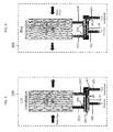
- the valve member 30 in FIG. 3 defines the two combined flow paths 301, which are identified by the dashed arrows in FIG. 3 , as being substantially parallel with each other except for the lateral portion 302 of the one of the second combined flow paths 301.
- the valve member 30 of the reconfigurable valve 10 may be positioned in the second position by the controller 60 prior to installation. Subsequently, the reconfigurable valve 10 may be disposed in the aircraft 20 to fluidly couple the compressor outlet 103 with the right condenser inlet 1012 and to fluidly couple the right condenser outlet 1014 with the receiver inlet 102. As such, the valve member 30 in FIG. 4 defines the two combined flow paths 300, which are identified by the dashed arrows in FIG. 4 , as crisscrossing with each other.
- VCP condensers 101 shown in FIGS 3 and 4 are constructed in similar manners but have opposing functionalities. That is, the left condenser outlet 1011 of FIG. 3 in which RAM flow proceeds in the first direction from left-to-right is similar in construction and relative position to the right condenser inlet 1012 of FIG. 4 in which the RAM flow proceeds in the second direction from right-to-left. Concurrently, the left condenser inlet 1013 of FIG. 3 in which RAM flow proceeds again in the first direction from left-to-right is similar in construction and relative position as the right condenser outlet 1014 of FIG. 4 in which the RAM flow proceeds again in the second direction from right-to-left.
Landscapes
- Engineering & Computer Science (AREA)
- General Engineering & Computer Science (AREA)
- Mechanical Engineering (AREA)
- Valve Housings (AREA)
Abstract
Description
- The subject matter disclosed herein relates to a valve, more particularly a reconfigurable valve and, more particularly, to an aircraft including a reconfigurable valve.
- For an aircraft that uses a vapor cycle cooling system, the vapor cycle cooling system typically requires two ram cooled vapor cycle packs (VCPs). The direction of refrigerant flow through the VCP is dependent on which side of the aircraft the VCP is installed. Each VCP includes two independently actuated three-way valves that enable the refrigerant flow through a multi-pass condenser to be reconfigured in order to accommodate RAM flow from opposite sides of the aircraft.
- According to a first aspect of the invention, a valve is provided. The valve includes a body defining an interior and apertures, additional bodies each having opposed, open ends and being respectively coupled to each of the apertures at one of the respective open ends to define a flow path through each of the additional bodies and into the interior and a valve member. The valve member is disposable in first and second positions in the interior. In the first position, the valve member fluidly couples pairs of the additional bodies with one another via first combined flow paths that crisscross through the interior. In the second position, the valve member fluidly couples different pairs of the additional bodies with one another via second combined flow paths that are substantially parallel through the interior.
- According to another aspect of the invention, an aircraft is provided and includes a receiver inlet, a compressor outlet, left and right condenser inlets, left and right condenser outlets and a reconfigurable valve disposable to fluidly couple the compressor outlet with the right condenser inlet and the right condenser outlet with the receiver inlet or to fluidly couple the compressor outlet with the left condenser inlet and the left condenser outlet with the receiver inlet. The reconfigurable valve may be a valve according to the first aspect of the invention.
- According to yet another aspect of the invention, a method of valve installation for an aircraft is provided. The method includes disposing a reconfigurable valve to fluidly couple one of a compressor outlet with a right condenser inlet and a right condenser outlet with a receiver inlet and the compressor outlet with a left condenser inlet and a left condenser outlet with the receiver inlet, reconfiguring the reconfigurable valve and disposing the reconfigurable valve to fluidly couple the other of the compressor outlet with a left condenser inlet and a left condenser outlet with the receiver inlet and the compressor outlet with the right condenser inlet and the right condenser outlet with the receiver inlet.
- These and other advantages and features will become more apparent from the following description taken in conjunction with the drawings.
- The subject matter, which is regarded as the invention, is particularly pointed out and distinctly claimed in the claims at the conclusion of the specification. The foregoing and other features, and advantages of the invention are apparent from the following detailed description taken in conjunction with the accompanying drawings in which:
-
FIG. 1 is a perspective view of a reconfigurable valve in accordance with embodiments; -
FIG. 2 is an axial view of the reconfigurable valve ofFIG. 1 ; -
FIG. 3 is a plan view of the reconfigurable valve ofFIG. 1 disposed for left side installation; and -
FIG. 4 is a plan view of the reconfigurable valve ofFIG. 1 disposed for right side installation. - The detailed description explains embodiments of the invention, together with advantages and features, by way of example with reference to the drawings.
- A reconfigurable valve, as described herein, may be employed to replace the two independently actuated three-way valves normally included in a VCP in an aircraft. The reconfigurable valve enables refrigerant flow to be reversed through the condenser to thereby allow for a single vapor cycle cooling system (VCS) to be used in symmetric aircraft installations (otherwise the multiple valves or handed packs as noted above would be required). The use of the reconfigurable valve avoids the need for asymmetric RAM circuits, which can impact system performance, and fewer parts and thus increased reliability. In addition, the reconfigurable valve may provide a visual RH/LH position indication for mechanics to confirm the pack has been properly configured to operate on the side of the aircraft that it is installed in.
- With reference to
FIGS. 1 and 2 , areconfigurable valve 10 is provided. Thereconfigurable valve 10 includes abody 11 that is formed to define aninterior 12 and a set ofapertures 13. In accordance with embodiments, thebody 11 may be provided as atubular element 110 with closed,long ends apertures 13 as fourapertures 13 along sides of thetubular element 110 in, for example, a 2X2 staggered formation (seeFIG. 1 ). - The
reconfigurable valve 10 further includesadditional bodies 20 and avalve member 30. Where thebody 11 defines fourapertures 13, theadditional bodies 20 may be provided in a set of fouradditional bodies 20 as well. Eachadditional body 20 has opposed,open ends apertures 13 at one of the respective open ends (i.e.,end 21, which is formed to fit onto thebody 11. The fouradditional bodies 20 thus define fourrespective flow paths 40 through theadditional bodies 20 and into theinterior 12. In an embodiment where thereconfigurable valve 10 is provided in an aircraft, the fouradditional bodies 20 may each be coupled to a compressor outlet, a VCP condenser inlet (left or right side), a VCP condenser outlet (left or right side) and a receiver inlet as will be described below. - The
valve member 30 is disposable in theinterior 12 in a first position or a second position. In the first position, thevalve member 30 fluidly couples pairs of theadditional bodies 20 with one another via first combined flow paths 300 (see the dashed arrows inFIG. 4 ) that crisscross with each other through theinterior 12. In the second position, thevalve member 30 fluidly couples different pairs of theadditional bodies 20 with one another via second combined flow paths 301 (see the dashed arrows inFIG. 3 ) that are substantially parallel with each other through theinterior 12 though it is to be understood that alateral portion 302 of one of the second combinedflow paths 301 is defined through but is insulated from the other of the second combinedflow paths 301. In the case of fourapertures 13 and fouradditional bodies 20, thevalve member 30 fluidly couples two pairs of the fouradditional bodies 20 with one another via theinterior 12 in the first position and fluidly couples two different pairs of the fouradditional bodies 20 with one another via theinterior 12 in the second position such that, in each case, thevalve member 30 forms two combined flow paths 300 (in the case where thevalve member 30 is in the first position) and 301 (in the case where thevalve member 30 is in the second position). - As shown in
FIG. 1 , thevalve member 30 may have a dumbbell shape with a hollow,central shaft 31 andvalve portions 32 at opposite, distal ends of the hollow,central shaft 31. The hollow,central shaft 31 has a smaller dimension than the body 11 (i.e., the hollow,central shaft 31 has a smaller diameter than the tubular element 110) while thevalve portions 32 have certain similar dimensions as the body 11 (i.e., outer diameters of thevalve portions 32 are similar to the diameter of the tubular element 110). Thevalve member 30 is disposable in theinterior 12 of thebody 11 such that the hollow,central shaft 31 defines an annulus 33 between an exterior surface thereof, an interior surface of thebody 11 and interior, axial surfaces of thevalve portions 32. Thevalve portions 32 isolate the annulus 33 from fluid communication with aninterior 34 of the hollow,central shaft 31. - In accordance with embodiment,
seal elements 50 may be disposed on outer diameters of thevalve portions 32 such that theseal elements 50 are interposed between thevalve portions 32 and the interior surface of thebody 11. Theseal portions 50 may include O-rings or another similar feature. - The
reconfigurable valve 10 may further include acontroller 60. Thecontroller 60 is configured to selectively position thevalve member 30 in one of the first portion or the second position. In accordance with embodiments, thecontroller 60 and thevalve member 30 may each include ferromagnetic materials such that thecontroller 60 may electromagnetically position thevalve member 30. That is, thecontroller 60 may be slidably coupled to a side of thebody 11, which is adjacent to the sides theadditional bodies 20 are coupled to (seeFIG. 2 ). When thecontroller 60 is slid along the side of thebody 11, thecontroller 60 causes thevalve member 30 to correspondingly translate in position. - In accordance with embodiments of the invention, the
valve member 30 should be maintained in the first or the second position until it is to be serviced, repaired or replaced. Thus, movement from the first to the second position and vice versa should not occur under normal circumstances. However, it is possible that thereconfigurable valve 10 may be employed in certain applications where reversed flows occur. In these cases, thecontroller 60 may be configured to selectively position thevalve member 30 in an active state. That is, thecontroller 60 may position thevalve member 30 in the first position and then reposition thevalve member 30 in the second position during an operation of thereconfigurable valve 10. Similarly, thecontroller 60 may position thevalve member 30 in the second position and then reposition thevalve member 30 in the first position during an operation of thereconfigurable valve 10. - With reference to
FIGS 3 and 4 , thereconfigurable valve 10 may be provided for use in anaircraft 100 in a left side installation (seeFIG. 3 ), in which RAM air flow would be expected to flow in a first direction, or a right side installation (seeFIG. 4 ), in which the RAM air flow would be expected to flow a second direction opposite the first direction. As shown inFIGS. 3 and 4 , theaircraft 100 includes aVCP condenser 101, areceiver inlet 102, acompressor outlet 103, a left condenser outlet 1011 (seeFIG. 3 ), a right condenser inlet 1012 (seeFIG. 4 ), a left condenser inlet 1013 (seeFIG. 3 ) and a right condenser outlet 1014 (seeFIG. 4 ). - For the left side installation of
FIG. 3 , thevalve member 30 of thereconfigurable valve 10 may be positioned in the first position by thecontroller 60 prior to installation. Subsequently, thereconfigurable valve 10 may be disposed in theaircraft 20 to fluidly couple thecompressor outlet 103 with theleft condenser inlet 1013 and to fluidly couple theleft condenser outlet 1011 with thereceiver inlet 102. As such, thevalve member 30 inFIG. 3 defines the two combinedflow paths 301, which are identified by the dashed arrows inFIG. 3 , as being substantially parallel with each other except for thelateral portion 302 of the one of the second combinedflow paths 301. By contrast, for the right side installation ofFIG. 4 , thevalve member 30 of thereconfigurable valve 10 may be positioned in the second position by thecontroller 60 prior to installation. Subsequently, thereconfigurable valve 10 may be disposed in theaircraft 20 to fluidly couple thecompressor outlet 103 with theright condenser inlet 1012 and to fluidly couple theright condenser outlet 1014 with thereceiver inlet 102. As such, thevalve member 30 inFIG. 4 defines the two combinedflow paths 300, which are identified by the dashed arrows inFIG. 4 , as crisscrossing with each other. - It is to be understood that the
VCP condensers 101 shown inFIGS 3 and 4 are constructed in similar manners but have opposing functionalities. That is, theleft condenser outlet 1011 ofFIG. 3 in which RAM flow proceeds in the first direction from left-to-right is similar in construction and relative position to theright condenser inlet 1012 ofFIG. 4 in which the RAM flow proceeds in the second direction from right-to-left. Concurrently, theleft condenser inlet 1013 ofFIG. 3 in which RAM flow proceeds again in the first direction from left-to-right is similar in construction and relative position as theright condenser outlet 1014 ofFIG. 4 in which the RAM flow proceeds again in the second direction from right-to-left. - Thus, it may be understood that the
aircraft 100 may be provided with tworeconfigurable valves 10 with one disposed in the left side installation (and thevalve member 30 disposed in the first position by the controller 60) and one disposed in the right side installation (and thevalve member 30 disposed in the second position by the controller 60). In such a case, the tworeconfigurable valves 10 may be interchangeable with one another. Thus, during servicing, repair or replacement, thereconfigurable valves 10 may be removed from theaircraft 100, reconfigured and re-installed. This installation requires that the position of thevalve member 30 be determined such that thereconfigurable valve 10 can be installed in the correct side. - While the invention has been described in detail in connection with only a limited number of embodiments, it should be readily understood that the invention is not limited to such disclosed embodiments. Rather, the invention can be modified to incorporate any number of variations, alterations, substitutions or equivalent arrangements not heretofore described, but which are commensurate with the scope of the invention. Additionally, while various embodiments of the invention have been described, it is to be understood that aspects of the invention may include only some of the described embodiments. Accordingly, the invention is not to be seen as limited by the foregoing description, but is only limited by the scope of the appended claims.
Claims (15)
- A valve (10), comprising:a body (11) defining an interior (12) and apertures (13);additional bodies (20) each having opposed, open ends and being respectively coupled to each of the apertures at one of the respective open ends (21,22) to define a flow path (40) through each of the additional bodies (20) and into the interior (12); anda valve member (30), which is disposable in first and second positions in the interior (12), wherein:in the first position, the valve member (30) fluidly couples pairs of the additional bodies (20) with one another via first combined flow paths that crisscross through the interior (12), andin the second position, the valve member (30) fluidly couples different pairs of the additional bodies (20) with one another via second combined flow paths that are substantially parallel through the interior (12).
- The valve according to claim 1, wherein the apertures (13) are provided as four apertures (13) and the additional bodies (20) are correspondingly provided as four additional bodies (20).
- The valve according to claim 2, wherein the valve member (30) fluidly couples two pairs of the four additional bodies (20) with one another via the interior (12) in the first position and fluidly couples two different pairs of the four additional bodies (20) with one another via the interior (12) in the second position.
- The valve according to any preceding claim, wherein the body (11) comprises a tubular element (110) with closed, long ends (111,112).
- The valve according to claim 4, wherein the apertures (13) are defined along sides of the tubular element (110).
- The valve according to claim 4 or 5, wherein the apertures (13) are defined in a staggered formation along sides of the tubular element (110).
- The valve according to any preceding claim, wherein the valve member (30) comprises:a hollow, central shaft (31); andvalve portions (32) at distal ends of the hollow, central shaft (31),the hollow, central shaft (31) defining an annulus (33) between an exterior surface thereof, an interior surface of the body (11) and interior surfaces of the valve portions (32), andthe valve portions isolating the annulus (33) from fluid communication with an interior (34) of the hollow, central shaft (31).
- The valve according to any preceding claim, further comprising a controller (60) configured to selectively position the valve member (30) in one of the first or second positions.
- The valve according to claim 8, wherein the controller (60) is slidably coupled to a side of the body (11).
- The valve according to claim 8 or 9, wherein the controller (60) is configured to selectively position the valve member (30) in an active state.
- An aircraft, comprising:a receiver inlet (102);a compressor outlet (103);left and right condenser inlets (1013,1012);left and right condenser outlets (1011,1014); anda reconfigurable valve (30) disposable to fluidly couple the compressor outlet (103) with the right condenser inlet (1012) and the right condenser outlet (1014) with the receiver inlet (102) or to fluidly couple the compressor outlet (103) with the left condenser inlet (1013) and the left condenser outlet (1011) with the receiver inlet (102).
- The aircraft according to claim 11, wherein the reconfigurable valve (30) is reconfigurable and configured for left or right side aircraft installation.
- The aircraft according to claim 11 or 12, further comprising a controller (60) configured to re-configure the reconfigurable valve (30).
- The aircraft according to claim 13, wherein the controller (60) electromagnetically re-configures the reconfigurable valve (30).
- The aircraft according to any of claims 11 to 14, wherein the reconfigurable valve (30) is provided as first and second reconfigurable valves, which are interchangeable.
Applications Claiming Priority (1)
| Application Number | Priority Date | Filing Date | Title |
|---|---|---|---|
| US13/856,153 US9255645B2 (en) | 2013-04-03 | 2013-04-03 | Reconfigurable valve |
Publications (2)
| Publication Number | Publication Date |
|---|---|
| EP2787258A1 true EP2787258A1 (en) | 2014-10-08 |
| EP2787258B1 EP2787258B1 (en) | 2017-05-03 |
Family
ID=50396997
Family Applications (1)
| Application Number | Title | Priority Date | Filing Date |
|---|---|---|---|
| EP14162831.3A Active EP2787258B1 (en) | 2013-04-03 | 2014-03-31 | Reconfigurable valve |
Country Status (2)
| Country | Link |
|---|---|
| US (1) | US9255645B2 (en) |
| EP (1) | EP2787258B1 (en) |
Families Citing this family (3)
| Publication number | Priority date | Publication date | Assignee | Title |
|---|---|---|---|---|
| DE102020101031B4 (en) | 2020-01-17 | 2022-11-03 | Hanon Systems | Device for controlling a flow and distributing a fluid in a fluid circuit |
| DE102020101030B4 (en) | 2020-01-17 | 2022-11-03 | Hanon Systems | Device for controlling a flow and distributing a fluid in a fluid circuit |
| US11454134B2 (en) * | 2020-08-05 | 2022-09-27 | General Electric Company | Damper control valve for a turbomachine |
Citations (5)
| Publication number | Priority date | Publication date | Assignee | Title |
|---|---|---|---|---|
| FR1506181A (en) * | 1965-12-28 | 1967-12-15 | Hermetic double deflection valve to control the reversal of cycles in refrigeration installations, functioning in particular as a heat pump | |
| JPS55100753U (en) * | 1978-12-30 | 1980-07-14 | ||
| US4361121A (en) * | 1980-04-17 | 1982-11-30 | Robert Bosch Gmbh | Control device for shutting off a diesel engine |
| JPS61192974A (en) * | 1985-02-20 | 1986-08-27 | Matsushita Refrig Co | Four way type valve for refrigerating cycle |
| JPS61181167U (en) * | 1985-04-30 | 1986-11-12 |
Family Cites Families (17)
| Publication number | Priority date | Publication date | Assignee | Title |
|---|---|---|---|---|
| US3719199A (en) * | 1971-10-01 | 1973-03-06 | Hydromation Syst Inc | Spool valve construction of modular parts |
| US3937253A (en) * | 1973-11-08 | 1976-02-10 | Lilja Duane F | Multiple fluid dispensing apparatus |
| US6415595B1 (en) | 2000-08-22 | 2002-07-09 | Hamilton Sundstrand Corporation | Integrated thermal management and coolant system for an aircraft |
| WO2005095874A1 (en) | 2004-03-31 | 2005-10-13 | Daikin Industries, Ltd. | Humidity controller |
| US7631661B2 (en) | 2004-08-23 | 2009-12-15 | Zhejiang Sanhua Co Ltd. | Straight flow reversing valve |
| US7124777B2 (en) | 2004-09-03 | 2006-10-24 | Ranco Incorporated Of Delaware | Reversing valve with flowsplitter |
| US7152416B2 (en) | 2004-09-08 | 2006-12-26 | Carrier Corporation | Hot gas bypass through four-way reversing valve |
| US7197890B2 (en) | 2004-09-10 | 2007-04-03 | Carrier Corporation | Valve for preventing unpowered reverse run at shutdown |
| US7272948B2 (en) | 2004-09-16 | 2007-09-25 | Carrier Corporation | Heat pump with reheat and economizer functions |
| US7275384B2 (en) | 2004-09-16 | 2007-10-02 | Carrier Corporation | Heat pump with reheat circuit |
| MX2007001452A (en) | 2005-06-03 | 2008-03-11 | Carrier Corp | Refrigerant charge control in a heat pump system with water heating. |
| CN100575818C (en) | 2005-06-03 | 2009-12-30 | 开利公司 | Heat pump system with auxiliary water heating |
| US7491037B2 (en) | 2005-08-05 | 2009-02-17 | Edwards Thomas C | Reversible valving system for use in pumps and compressing devices |
| WO2007121540A2 (en) | 2006-04-20 | 2007-11-01 | Springer Carrier Ltda | Heat pump system having auxiliary water heating and heat exchanger bypass |
| US8419512B2 (en) | 2006-10-10 | 2013-04-16 | Hdt Tactical Systems, Inc. | Vehicle cabin heating cooling and ventilation system |
| CN101668973B (en) * | 2007-03-31 | 2013-03-13 | 盾安美斯泰克公司(美国) | Pilot operated spool valve |
| CN101796355A (en) | 2007-08-28 | 2010-08-04 | 开利公司 | Thermally activated high efficiency heat pump |
-
2013
- 2013-04-03 US US13/856,153 patent/US9255645B2/en active Active
-
2014
- 2014-03-31 EP EP14162831.3A patent/EP2787258B1/en active Active
Patent Citations (5)
| Publication number | Priority date | Publication date | Assignee | Title |
|---|---|---|---|---|
| FR1506181A (en) * | 1965-12-28 | 1967-12-15 | Hermetic double deflection valve to control the reversal of cycles in refrigeration installations, functioning in particular as a heat pump | |
| JPS55100753U (en) * | 1978-12-30 | 1980-07-14 | ||
| US4361121A (en) * | 1980-04-17 | 1982-11-30 | Robert Bosch Gmbh | Control device for shutting off a diesel engine |
| JPS61192974A (en) * | 1985-02-20 | 1986-08-27 | Matsushita Refrig Co | Four way type valve for refrigerating cycle |
| JPS61181167U (en) * | 1985-04-30 | 1986-11-12 |
Also Published As
| Publication number | Publication date |
|---|---|
| US9255645B2 (en) | 2016-02-09 |
| US20140299199A1 (en) | 2014-10-09 |
| EP2787258B1 (en) | 2017-05-03 |
Similar Documents
| Publication | Publication Date | Title |
|---|---|---|
| EP2806244B1 (en) | Heat exchanger distribution assembly and method | |
| EP2787258B1 (en) | Reconfigurable valve | |
| EP2578967A2 (en) | Pressure Correcting Distributor for Heating and Cooling Systems | |
| RU2474771C2 (en) | Valve unit with inbuilt collector | |
| EP2956697B1 (en) | Modulating balance ported three way valve | |
| JP2008533415A (en) | Co-current heat exchanger with crimped channel inlet | |
| US9097364B2 (en) | Flow straightening seat ring and control valve having flow straightening seat ring | |
| US20130186604A1 (en) | Micro-channel heat exchanger including independent heat exchange circuits and method | |
| WO2019122462A1 (en) | Flow control valve | |
| US8505580B2 (en) | Reversing valve | |
| EP3690335A1 (en) | Improved high pressure water extraction device with shave off edge that feeds a low pressure chamber to improve water collection and drainage | |
| US9644905B2 (en) | Valve with flow modulation device for heat exchanger | |
| EP3054201A1 (en) | Self-acting pressure drain valve | |
| JP5442213B2 (en) | 3-way selector valve | |
| JP5275948B2 (en) | Four-way selector valve | |
| DE102020101031A1 (en) | Device for regulating a flow rate and distributing a fluid in a fluid circuit | |
| JP5275947B2 (en) | Four-way selector valve | |
| CN106895179B (en) | Electronic expansion device | |
| EP3719419B1 (en) | Multi-port variable expansion plunger valve | |
| US9909822B2 (en) | Channel guide distributor | |
| CN106949676A (en) | A kind of bidirectional throttling valve of unidirectional variable restrictor | |
| WO2016113898A1 (en) | Pressure reducing device for cooling system and cooling system | |
| EP3444554A1 (en) | Heat exchanger assembly | |
| US9372019B2 (en) | Dual circuit refrigerant condenser | |
| EP2817572B1 (en) | An accumulator for a refrigerant recovery and recharge device |
Legal Events
| Date | Code | Title | Description |
|---|---|---|---|
| PUAI | Public reference made under article 153(3) epc to a published international application that has entered the european phase |
Free format text: ORIGINAL CODE: 0009012 |
|
| 17P | Request for examination filed |
Effective date: 20140331 |
|
| AK | Designated contracting states |
Kind code of ref document: A1 Designated state(s): AL AT BE BG CH CY CZ DE DK EE ES FI FR GB GR HR HU IE IS IT LI LT LU LV MC MK MT NL NO PL PT RO RS SE SI SK SM TR |
|
| AX | Request for extension of the european patent |
Extension state: BA ME |
|
| R17P | Request for examination filed (corrected) |
Effective date: 20150407 |
|
| RBV | Designated contracting states (corrected) |
Designated state(s): AL AT BE BG CH CY CZ DE DK EE ES FI FR GB GR HR HU IE IS IT LI LT LU LV MC MK MT NL NO PL PT RO RS SE SI SK SM TR |
|
| RIC1 | Information provided on ipc code assigned before grant |
Ipc: F25B 41/04 20060101ALI20160909BHEP Ipc: F16K 11/07 20060101AFI20160909BHEP Ipc: F28F 27/02 20060101ALI20160909BHEP Ipc: B64D 13/06 20060101ALI20160909BHEP Ipc: F16K 31/08 20060101ALI20160909BHEP |
|
| GRAP | Despatch of communication of intention to grant a patent |
Free format text: ORIGINAL CODE: EPIDOSNIGR1 |
|
| INTG | Intention to grant announced |
Effective date: 20161118 |
|
| GRAS | Grant fee paid |
Free format text: ORIGINAL CODE: EPIDOSNIGR3 |
|
| GRAA | (expected) grant |
Free format text: ORIGINAL CODE: 0009210 |
|
| AK | Designated contracting states |
Kind code of ref document: B1 Designated state(s): AL AT BE BG CH CY CZ DE DK EE ES FI FR GB GR HR HU IE IS IT LI LT LU LV MC MK MT NL NO PL PT RO RS SE SI SK SM TR |
|
| REG | Reference to a national code |
Ref country code: GB Ref legal event code: FG4D |
|
| REG | Reference to a national code |
Ref country code: AT Ref legal event code: REF Ref document number: 890366 Country of ref document: AT Kind code of ref document: T Effective date: 20170515 Ref country code: CH Ref legal event code: EP |
|
| REG | Reference to a national code |
Ref country code: IE Ref legal event code: FG4D |
|
| REG | Reference to a national code |
Ref country code: DE Ref legal event code: R096 Ref document number: 602014009213 Country of ref document: DE |
|
| REG | Reference to a national code |
Ref country code: NL Ref legal event code: MP Effective date: 20170503 |
|
| REG | Reference to a national code |
Ref country code: AT Ref legal event code: MK05 Ref document number: 890366 Country of ref document: AT Kind code of ref document: T Effective date: 20170503 |
|
| REG | Reference to a national code |
Ref country code: LT Ref legal event code: MG4D |
|
| PG25 | Lapsed in a contracting state [announced via postgrant information from national office to epo] |
Ref country code: HR Free format text: LAPSE BECAUSE OF FAILURE TO SUBMIT A TRANSLATION OF THE DESCRIPTION OR TO PAY THE FEE WITHIN THE PRESCRIBED TIME-LIMIT Effective date: 20170503 Ref country code: GR Free format text: LAPSE BECAUSE OF FAILURE TO SUBMIT A TRANSLATION OF THE DESCRIPTION OR TO PAY THE FEE WITHIN THE PRESCRIBED TIME-LIMIT Effective date: 20170804 Ref country code: ES Free format text: LAPSE BECAUSE OF FAILURE TO SUBMIT A TRANSLATION OF THE DESCRIPTION OR TO PAY THE FEE WITHIN THE PRESCRIBED TIME-LIMIT Effective date: 20170503 Ref country code: LT Free format text: LAPSE BECAUSE OF FAILURE TO SUBMIT A TRANSLATION OF THE DESCRIPTION OR TO PAY THE FEE WITHIN THE PRESCRIBED TIME-LIMIT Effective date: 20170503 Ref country code: AT Free format text: LAPSE BECAUSE OF FAILURE TO SUBMIT A TRANSLATION OF THE DESCRIPTION OR TO PAY THE FEE WITHIN THE PRESCRIBED TIME-LIMIT Effective date: 20170503 Ref country code: FI Free format text: LAPSE BECAUSE OF FAILURE TO SUBMIT A TRANSLATION OF THE DESCRIPTION OR TO PAY THE FEE WITHIN THE PRESCRIBED TIME-LIMIT Effective date: 20170503 Ref country code: NO Free format text: LAPSE BECAUSE OF FAILURE TO SUBMIT A TRANSLATION OF THE DESCRIPTION OR TO PAY THE FEE WITHIN THE PRESCRIBED TIME-LIMIT Effective date: 20170803 |
|
| PG25 | Lapsed in a contracting state [announced via postgrant information from national office to epo] |
Ref country code: SE Free format text: LAPSE BECAUSE OF FAILURE TO SUBMIT A TRANSLATION OF THE DESCRIPTION OR TO PAY THE FEE WITHIN THE PRESCRIBED TIME-LIMIT Effective date: 20170503 Ref country code: BG Free format text: LAPSE BECAUSE OF FAILURE TO SUBMIT A TRANSLATION OF THE DESCRIPTION OR TO PAY THE FEE WITHIN THE PRESCRIBED TIME-LIMIT Effective date: 20170803 Ref country code: NL Free format text: LAPSE BECAUSE OF FAILURE TO SUBMIT A TRANSLATION OF THE DESCRIPTION OR TO PAY THE FEE WITHIN THE PRESCRIBED TIME-LIMIT Effective date: 20170503 Ref country code: RS Free format text: LAPSE BECAUSE OF FAILURE TO SUBMIT A TRANSLATION OF THE DESCRIPTION OR TO PAY THE FEE WITHIN THE PRESCRIBED TIME-LIMIT Effective date: 20170503 Ref country code: LV Free format text: LAPSE BECAUSE OF FAILURE TO SUBMIT A TRANSLATION OF THE DESCRIPTION OR TO PAY THE FEE WITHIN THE PRESCRIBED TIME-LIMIT Effective date: 20170503 Ref country code: IS Free format text: LAPSE BECAUSE OF FAILURE TO SUBMIT A TRANSLATION OF THE DESCRIPTION OR TO PAY THE FEE WITHIN THE PRESCRIBED TIME-LIMIT Effective date: 20170903 Ref country code: PL Free format text: LAPSE BECAUSE OF FAILURE TO SUBMIT A TRANSLATION OF THE DESCRIPTION OR TO PAY THE FEE WITHIN THE PRESCRIBED TIME-LIMIT Effective date: 20170503 |
|
| PG25 | Lapsed in a contracting state [announced via postgrant information from national office to epo] |
Ref country code: DK Free format text: LAPSE BECAUSE OF FAILURE TO SUBMIT A TRANSLATION OF THE DESCRIPTION OR TO PAY THE FEE WITHIN THE PRESCRIBED TIME-LIMIT Effective date: 20170503 Ref country code: SK Free format text: LAPSE BECAUSE OF FAILURE TO SUBMIT A TRANSLATION OF THE DESCRIPTION OR TO PAY THE FEE WITHIN THE PRESCRIBED TIME-LIMIT Effective date: 20170503 Ref country code: EE Free format text: LAPSE BECAUSE OF FAILURE TO SUBMIT A TRANSLATION OF THE DESCRIPTION OR TO PAY THE FEE WITHIN THE PRESCRIBED TIME-LIMIT Effective date: 20170503 Ref country code: RO Free format text: LAPSE BECAUSE OF FAILURE TO SUBMIT A TRANSLATION OF THE DESCRIPTION OR TO PAY THE FEE WITHIN THE PRESCRIBED TIME-LIMIT Effective date: 20170503 Ref country code: CZ Free format text: LAPSE BECAUSE OF FAILURE TO SUBMIT A TRANSLATION OF THE DESCRIPTION OR TO PAY THE FEE WITHIN THE PRESCRIBED TIME-LIMIT Effective date: 20170503 |
|
| REG | Reference to a national code |
Ref country code: DE Ref legal event code: R097 Ref document number: 602014009213 Country of ref document: DE |
|
| REG | Reference to a national code |
Ref country code: FR Ref legal event code: PLFP Year of fee payment: 5 |
|
| PG25 | Lapsed in a contracting state [announced via postgrant information from national office to epo] |
Ref country code: IT Free format text: LAPSE BECAUSE OF FAILURE TO SUBMIT A TRANSLATION OF THE DESCRIPTION OR TO PAY THE FEE WITHIN THE PRESCRIBED TIME-LIMIT Effective date: 20170503 Ref country code: SM Free format text: LAPSE BECAUSE OF FAILURE TO SUBMIT A TRANSLATION OF THE DESCRIPTION OR TO PAY THE FEE WITHIN THE PRESCRIBED TIME-LIMIT Effective date: 20170503 |
|
| PLBE | No opposition filed within time limit |
Free format text: ORIGINAL CODE: 0009261 |
|
| STAA | Information on the status of an ep patent application or granted ep patent |
Free format text: STATUS: NO OPPOSITION FILED WITHIN TIME LIMIT |
|
| 26N | No opposition filed |
Effective date: 20180206 |
|
| PG25 | Lapsed in a contracting state [announced via postgrant information from national office to epo] |
Ref country code: SI Free format text: LAPSE BECAUSE OF FAILURE TO SUBMIT A TRANSLATION OF THE DESCRIPTION OR TO PAY THE FEE WITHIN THE PRESCRIBED TIME-LIMIT Effective date: 20170503 |
|
| REG | Reference to a national code |
Ref country code: DE Ref legal event code: R119 Ref document number: 602014009213 Country of ref document: DE |
|
| REG | Reference to a national code |
Ref country code: CH Ref legal event code: PL |
|
| PG25 | Lapsed in a contracting state [announced via postgrant information from national office to epo] |
Ref country code: MC Free format text: LAPSE BECAUSE OF FAILURE TO SUBMIT A TRANSLATION OF THE DESCRIPTION OR TO PAY THE FEE WITHIN THE PRESCRIBED TIME-LIMIT Effective date: 20170503 |
|
| REG | Reference to a national code |
Ref country code: BE Ref legal event code: MM Effective date: 20180331 |
|
| REG | Reference to a national code |
Ref country code: IE Ref legal event code: MM4A |
|
| PG25 | Lapsed in a contracting state [announced via postgrant information from national office to epo] |
Ref country code: LU Free format text: LAPSE BECAUSE OF NON-PAYMENT OF DUE FEES Effective date: 20180331 |
|
| PG25 | Lapsed in a contracting state [announced via postgrant information from national office to epo] |
Ref country code: IE Free format text: LAPSE BECAUSE OF NON-PAYMENT OF DUE FEES Effective date: 20180331 Ref country code: DE Free format text: LAPSE BECAUSE OF NON-PAYMENT OF DUE FEES Effective date: 20181002 |
|
| PG25 | Lapsed in a contracting state [announced via postgrant information from national office to epo] |
Ref country code: CH Free format text: LAPSE BECAUSE OF NON-PAYMENT OF DUE FEES Effective date: 20180331 Ref country code: LI Free format text: LAPSE BECAUSE OF NON-PAYMENT OF DUE FEES Effective date: 20180331 Ref country code: BE Free format text: LAPSE BECAUSE OF NON-PAYMENT OF DUE FEES Effective date: 20180331 |
|
| PG25 | Lapsed in a contracting state [announced via postgrant information from national office to epo] |
Ref country code: MT Free format text: LAPSE BECAUSE OF NON-PAYMENT OF DUE FEES Effective date: 20180331 |
|
| PG25 | Lapsed in a contracting state [announced via postgrant information from national office to epo] |
Ref country code: TR Free format text: LAPSE BECAUSE OF FAILURE TO SUBMIT A TRANSLATION OF THE DESCRIPTION OR TO PAY THE FEE WITHIN THE PRESCRIBED TIME-LIMIT Effective date: 20170503 |
|
| PG25 | Lapsed in a contracting state [announced via postgrant information from national office to epo] |
Ref country code: HU Free format text: LAPSE BECAUSE OF FAILURE TO SUBMIT A TRANSLATION OF THE DESCRIPTION OR TO PAY THE FEE WITHIN THE PRESCRIBED TIME-LIMIT; INVALID AB INITIO Effective date: 20140331 Ref country code: PT Free format text: LAPSE BECAUSE OF FAILURE TO SUBMIT A TRANSLATION OF THE DESCRIPTION OR TO PAY THE FEE WITHIN THE PRESCRIBED TIME-LIMIT Effective date: 20170503 |
|
| PG25 | Lapsed in a contracting state [announced via postgrant information from national office to epo] |
Ref country code: MK Free format text: LAPSE BECAUSE OF NON-PAYMENT OF DUE FEES Effective date: 20170503 Ref country code: CY Free format text: LAPSE BECAUSE OF FAILURE TO SUBMIT A TRANSLATION OF THE DESCRIPTION OR TO PAY THE FEE WITHIN THE PRESCRIBED TIME-LIMIT Effective date: 20170503 |
|
| PG25 | Lapsed in a contracting state [announced via postgrant information from national office to epo] |
Ref country code: AL Free format text: LAPSE BECAUSE OF FAILURE TO SUBMIT A TRANSLATION OF THE DESCRIPTION OR TO PAY THE FEE WITHIN THE PRESCRIBED TIME-LIMIT Effective date: 20170503 |
|
| P01 | Opt-out of the competence of the unified patent court (upc) registered |
Effective date: 20230522 |
|
| PGFP | Annual fee paid to national office [announced via postgrant information from national office to epo] |
Ref country code: GB Payment date: 20260220 Year of fee payment: 13 |
|
| PGFP | Annual fee paid to national office [announced via postgrant information from national office to epo] |
Ref country code: FR Payment date: 20260219 Year of fee payment: 13 |