EP2787234A1 - Pièce mécanique pour applications horlogères ou microtechniques - Google Patents
Pièce mécanique pour applications horlogères ou microtechniques Download PDFInfo
- Publication number
- EP2787234A1 EP2787234A1 EP14162501.2A EP14162501A EP2787234A1 EP 2787234 A1 EP2787234 A1 EP 2787234A1 EP 14162501 A EP14162501 A EP 14162501A EP 2787234 A1 EP2787234 A1 EP 2787234A1
- Authority
- EP
- European Patent Office
- Prior art keywords
- mechanical part
- rings
- sleeve
- ceramic
- part according
- Prior art date
- Legal status (The legal status is an assumption and is not a legal conclusion. Google has not performed a legal analysis and makes no representation as to the accuracy of the status listed.)
- Granted
Links
Images



Classifications
-
- F—MECHANICAL ENGINEERING; LIGHTING; HEATING; WEAPONS; BLASTING
- F16—ENGINEERING ELEMENTS AND UNITS; GENERAL MEASURES FOR PRODUCING AND MAINTAINING EFFECTIVE FUNCTIONING OF MACHINES OR INSTALLATIONS; THERMAL INSULATION IN GENERAL
- F16C—SHAFTS; FLEXIBLE SHAFTS; ELEMENTS OR CRANKSHAFT MECHANISMS; ROTARY BODIES OTHER THAN GEARING ELEMENTS; BEARINGS
- F16C19/00—Bearings with rolling contact, for exclusively rotary movement
- F16C19/02—Bearings with rolling contact, for exclusively rotary movement with bearing balls essentially of the same size in one or more circular rows
- F16C19/14—Bearings with rolling contact, for exclusively rotary movement with bearing balls essentially of the same size in one or more circular rows for both radial and axial load
- F16C19/16—Bearings with rolling contact, for exclusively rotary movement with bearing balls essentially of the same size in one or more circular rows for both radial and axial load with a single row of balls
- F16C19/163—Bearings with rolling contact, for exclusively rotary movement with bearing balls essentially of the same size in one or more circular rows for both radial and axial load with a single row of balls with angular contact
- F16C19/166—Four-point-contact ball bearings
-
- F—MECHANICAL ENGINEERING; LIGHTING; HEATING; WEAPONS; BLASTING
- F16—ENGINEERING ELEMENTS AND UNITS; GENERAL MEASURES FOR PRODUCING AND MAINTAINING EFFECTIVE FUNCTIONING OF MACHINES OR INSTALLATIONS; THERMAL INSULATION IN GENERAL
- F16C—SHAFTS; FLEXIBLE SHAFTS; ELEMENTS OR CRANKSHAFT MECHANISMS; ROTARY BODIES OTHER THAN GEARING ELEMENTS; BEARINGS
- F16C35/00—Rigid support of bearing units; Housings, e.g. caps, covers
- F16C35/04—Rigid support of bearing units; Housings, e.g. caps, covers in the case of ball or roller bearings
- F16C35/042—Housings for rolling element bearings for rotary movement
-
- F—MECHANICAL ENGINEERING; LIGHTING; HEATING; WEAPONS; BLASTING
- F16—ENGINEERING ELEMENTS AND UNITS; GENERAL MEASURES FOR PRODUCING AND MAINTAINING EFFECTIVE FUNCTIONING OF MACHINES OR INSTALLATIONS; THERMAL INSULATION IN GENERAL
- F16C—SHAFTS; FLEXIBLE SHAFTS; ELEMENTS OR CRANKSHAFT MECHANISMS; ROTARY BODIES OTHER THAN GEARING ELEMENTS; BEARINGS
- F16C35/00—Rigid support of bearing units; Housings, e.g. caps, covers
- F16C35/04—Rigid support of bearing units; Housings, e.g. caps, covers in the case of ball or roller bearings
- F16C35/06—Mounting or dismounting of ball or roller bearings; Fixing them onto shaft or in housing
- F16C35/07—Fixing them on the shaft or housing with interposition of an element
- F16C35/077—Fixing them on the shaft or housing with interposition of an element between housing and outer race ring
-
- G—PHYSICS
- G04—HOROLOGY
- G04B—MECHANICALLY-DRIVEN CLOCKS OR WATCHES; MECHANICAL PARTS OF CLOCKS OR WATCHES IN GENERAL; TIME PIECES USING THE POSITION OF THE SUN, MOON OR STARS
- G04B31/00—Bearings; Point suspensions or counter-point suspensions; Pivot bearings; Single parts therefor
- G04B31/004—Bearings; Point suspensions or counter-point suspensions; Pivot bearings; Single parts therefor characterised by the material used
-
- G—PHYSICS
- G04—HOROLOGY
- G04B—MECHANICALLY-DRIVEN CLOCKS OR WATCHES; MECHANICAL PARTS OF CLOCKS OR WATCHES IN GENERAL; TIME PIECES USING THE POSITION OF THE SUN, MOON OR STARS
- G04B5/00—Automatic winding up
- G04B5/02—Automatic winding up by self-winding caused by the movement of the watch
- G04B5/18—Supports, suspensions or guide arrangements, for oscillating weights
- G04B5/19—Suspension of the oscillating weight at its centre of rotation
-
- F—MECHANICAL ENGINEERING; LIGHTING; HEATING; WEAPONS; BLASTING
- F16—ENGINEERING ELEMENTS AND UNITS; GENERAL MEASURES FOR PRODUCING AND MAINTAINING EFFECTIVE FUNCTIONING OF MACHINES OR INSTALLATIONS; THERMAL INSULATION IN GENERAL
- F16C—SHAFTS; FLEXIBLE SHAFTS; ELEMENTS OR CRANKSHAFT MECHANISMS; ROTARY BODIES OTHER THAN GEARING ELEMENTS; BEARINGS
- F16C2206/00—Materials with ceramics, cermets, hard carbon or similar non-metallic hard materials as main constituents
- F16C2206/40—Ceramics, e.g. carbides, nitrides, oxides, borides of a metal
- F16C2206/42—Ceramics, e.g. carbides, nitrides, oxides, borides of a metal based on ceramic oxides
- F16C2206/48—Ceramics, e.g. carbides, nitrides, oxides, borides of a metal based on ceramic oxides based on zirconia (ZrO2)
-
- F—MECHANICAL ENGINEERING; LIGHTING; HEATING; WEAPONS; BLASTING
- F16—ENGINEERING ELEMENTS AND UNITS; GENERAL MEASURES FOR PRODUCING AND MAINTAINING EFFECTIVE FUNCTIONING OF MACHINES OR INSTALLATIONS; THERMAL INSULATION IN GENERAL
- F16C—SHAFTS; FLEXIBLE SHAFTS; ELEMENTS OR CRANKSHAFT MECHANISMS; ROTARY BODIES OTHER THAN GEARING ELEMENTS; BEARINGS
- F16C2300/00—Application independent of particular apparatuses
- F16C2300/10—Application independent of particular apparatuses related to size
- F16C2300/12—Small applications, e.g. miniature bearings
-
- F—MECHANICAL ENGINEERING; LIGHTING; HEATING; WEAPONS; BLASTING
- F16—ENGINEERING ELEMENTS AND UNITS; GENERAL MEASURES FOR PRODUCING AND MAINTAINING EFFECTIVE FUNCTIONING OF MACHINES OR INSTALLATIONS; THERMAL INSULATION IN GENERAL
- F16C—SHAFTS; FLEXIBLE SHAFTS; ELEMENTS OR CRANKSHAFT MECHANISMS; ROTARY BODIES OTHER THAN GEARING ELEMENTS; BEARINGS
- F16C2316/00—Apparatus in health or amusement
- F16C2316/10—Apparatus in health or amusement in medical appliances, e.g. in diagnosis, dentistry, instruments, prostheses, medical imaging appliances
- F16C2316/13—Dental machines
-
- F—MECHANICAL ENGINEERING; LIGHTING; HEATING; WEAPONS; BLASTING
- F16—ENGINEERING ELEMENTS AND UNITS; GENERAL MEASURES FOR PRODUCING AND MAINTAINING EFFECTIVE FUNCTIONING OF MACHINES OR INSTALLATIONS; THERMAL INSULATION IN GENERAL
- F16C—SHAFTS; FLEXIBLE SHAFTS; ELEMENTS OR CRANKSHAFT MECHANISMS; ROTARY BODIES OTHER THAN GEARING ELEMENTS; BEARINGS
- F16C2370/00—Apparatus relating to physics, e.g. instruments
Definitions
- the present invention relates to a mechanical part, in particular a mechanical part for horological or microtechnical applications, in the medical field, or in any other industry.
- the present invention relates more particularly to a mechanical part comprising a ball bearing.
- the ball bearing described in this document has the advantage of a very high durability while eliminating the need for lubrication through the use of hard ceramic balls.
- the ring external and steel inner rings eventually wear out due to friction with very hard balls.
- An object of the present invention is to provide a mechanical part equipped with a ball bearing with three or four contact points for watchmaking or microtechnical applications, in the medical or industrial field, which comprises balls and ceramic rings, and which is free from the problems of the prior art.
- the socket can be made for example of steel or other machinable metal with high accuracy.
- the ring or rings are held without glue, in a precisely defined location.
- This outer sleeve may be provided with a toothing.
- the outer sleeve is made of steel which offers the advantage of being able to be machined with a very high precision to make a precision toothing, while the ring inside this sleeve is ceramic to reduce friction in the rolling and increase their resistance.
- the bearing comprises a fixed inner ring and two rotating outer rings held by the sleeve.
- This construction is particularly suitable for a ball bearing for the oscillating weight of a watch movement for a mechanical watch with automatic winding.
- a cage can be provided between the outer rings to separate the balls.
- the outer peripheral portion of the sleeve may be at least partially threaded, to allow to screw an external nut screwed on the thread. This nut keeps the winding mass in position.
- the peripheral portion of the sleeve may comprise a peripheral toothing for transmitting the oscillatory movement of the oscillating mass to the winding mechanism of the movement.
- the claimed construction can, however, also be applied to different bearings, including bearings having two inner rings and an outer ring, and / or bearings having one or more rotating inner rings and one or more fixed outer rings.
- the present invention also relates to the attachment of an oscillating mass to a bearing.
- the mechanical part illustrated by way of example on Figures 1 to 3 is intended for the automatic winding of a mechanical watch thanks to the oscillations of an oscillating mass 7.
- the solution of the present invention can however be applied to other mechanical parts in watchmaking and microtechnology, particularly in the medical or industry sectors.
- the mechanical part comprises a ball bearing with a fixed inner ring (or core) 2 and two rotating outer rings 4.
- Reference 40 designates the upper outer ring and the lower outer ring.
- the rings 2, 40, 41 are preferably ceramic, for example zirconium oxide (ZrO 2), and produced by molding, sintering and then rectification. The use of ceramics for the rings reduces their wear and reduces friction while making lubrication superfluous.
- the bearing further comprises ceramic balls 5, for example spherical balls of zirconium oxide, or balls of other shape.
- ceramic balls for example spherical balls of zirconium oxide, or balls of other shape.
- the use of ceramic also for the balls reduces their wear, and reduce friction while making lubrication superfluous.
- these different components dilate in the same proportions in case of temperature variation, so that the clearances between these components vary only slightly when the temperature changes.
- the inner and outer rings define a raceway 50 for the balls 5, preferably having four points of contact between the balls 5 and the rings 2, 40, 41.
- An optional cage 3 is advantageously provided between the upper and lower outer rings. and between the balls, to separate the balls 5 from each other.
- the spatial position of the outer rings 40, 41 is defined by a sleeve 1 in which the rings are driven.
- the sleeve 1 is advantageously made of steel or another precision-machined metal.
- the thickness of the sleeve in the direction perpendicular to the plane of rotation is substantially equal to or slightly greater than the total thickness of the outer rings, in order to hold these rings firmly, parallel to each other, without creating a useless overthickness.
- the outer periphery of the sleeve 1 comprises a peripheral toothing 11 in order to transmit the rotations of the sleeve 1 to the movement of the watch, in order to raise the mainspring of this movement.
- the sleeve 1 further comprises an external thread 10 at the outer periphery, on which a nut 6 is screwed.
- the nut 6 makes it possible to maintain the oscillating mass 7 by screwing it into openings 60.
- the oscillations of the oscillating mass 7 produced by the movements of the wearer of the watch are transmitted to the outer rings 4.
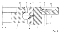
- FIGS. 4 and 5 illustrate a second variant of mechanical part according to the invention, wherein the outer periphery of the sleeve comprises a support 12 for a lock 8 for locking the oscillating mass 7 when the latch 8 is locked by turning a few degrees so as to block the oscillating weight.
- the figure 6 illustrates an alternative mechanical part according to the invention, wherein the oscillating mass 7 is crimped or driven around the sleeve 1.
- the sleeve 1 is thus constituted by a single piece of metal which fulfills three distinct functions: holding the outer rings 40, 41 in a precise position; allow the attachment of the oscillating mass 7 through the nut 6, or the lock 8, or by crimping; and meshing with the cog of the watch movement, through the toothing 11.
- the claimed solution could also be used in watchmaking as a mobile bearing, deflection bearing, roller bearing etc.
- the outer sleeve may be devoid of peripheral toothing, or provided with such toothing.
Landscapes
- Engineering & Computer Science (AREA)
- General Engineering & Computer Science (AREA)
- Mechanical Engineering (AREA)
- Physics & Mathematics (AREA)
- General Physics & Mathematics (AREA)
- Rolling Contact Bearings (AREA)
Abstract
Description
- La présente invention concerne une pièce mécanique, notamment une pièce mécanique pour applications horlogères ou microtechniques, dans le domaine médical, ou dans toute autre industrie. La présente invention concerne plus particulièrement une pièce mécanique comportant un roulement à billes.
- L'usage des roulements à billes ne cesse de se répandre et de s'appliquer à différentes technologies. On connait ainsi dans l'état de la technique des pièces mécaniques de très petites dimensions utilisées par exemple en horlogerie, notamment dans les montres bracelets, et dans des dispositifs médicaux ou industriels, et munies de roulements de billes.
- Afin d'assurer un frottement réduit, une usure minimale et une diminution du bruit, les roulements à billes de qualité sont les plus souvent isostatiques, c'est-à-dire que chaque bille est en contact avec les bagues internes et externes en trois points de contact uniquement. D'excellents roulements à billes à deux ou quatre points de contacts sont également connus.
- Le brevet
EP1520111 B2 au nom de la demanderesse décrit un exemple de roulement à billes subminiature à trois ou quatre points de contact, pour applications dans le domaine de l'horlogerie. Ce roulement comporte une bague extérieure et deux bagues intérieures, ainsi que des corps roulants réalisés en une céramique d'oxyde de zirconium. Le contenu de ce document est inclus ici par référence. - Le roulement à billes décrit dans ce document présente l'avantage d'une très grande durabilité tout en supprimant la nécessite d'une lubrification grâce à l'usage de billes en céramique dures. La bague externe et les bagues internes en acier finissent cependant par s'user suite au frottement avec les billes très dures. Ce document mentionne certes la possibilité de réaliser les bagues intérieures ou extérieures en céramique, mais sans donner d'exemple concret d'une telle mise en oeuvre.
- Des essais de construction ont démontré que la réalisation de roulements à billes subminiatures avec des bagues en céramique selon l'enseignement de
EP1520111 B2 , bien que possible, pose de grandes difficultés. En effet, il est extrêmement difficile de fabriquer avec la précision requise les bagues en céramique qui sont habituellement produites par moulage. Par conséquent, il subsiste souvent un jeu entre les bagues, ce qui conduit à un chemin de roulement pour les billes à l'intérieur du roulement dont les dimensions sont mal contrôlées. L'efficacité d'un tel roulement à billes réalisé avec des bagues en céramique est donc affectée, en sorte qu'en pratique l'homme du métier qui souhaite réaliser un roulement à billes selon l'enseignement de ce document préférera le plus souvent des bagues en acier ou dans un autre métal. - Un but de la présente invention est de proposer une pièce mécanique munie d'un roulement à billes à trois ou quatre points de contact pour application horlogères ou microtechniques, dans le domaine médical ou industriel, qui comporte des billes et des bagues en céramique, et qui soit exempt des problèmes de l'art antérieur.
- Selon l'invention, ces buts sont atteints notamment au moyen d'une pièce mécanique comportant un roulement à billes à trois ou quatre points de contact, ledit roulement comportant :
- une pluralité de billes en céramique ;
- au moins une bague interne en céramique et au moins une bague externe en céramique, lesdites bagues internes et externes définissant entre elles un chemin de roulement pour lesdites billes de manière à ce que chaque bille soit en contact avec lesdites bagues en trois ou quatre points,
- une douille externe dans lequel est logée ladite bague externe.
- Cette construction permet de maintenir la ou les bagues externes contre la surface interne de la douille. La douille peut être réalisée par exemple en acier ou dans un autre métal usinable avec une grande précision. Ainsi, la ou les bagues sont maintenues sans colle, en un emplacement précisément défini.
- Cette douille externe peut être munie d'une denture. Ainsi, la douille externe est en acier qui offre l'avantage de pouvoir être usiné avec une très grande précision pour fabriquer une denture de précision, tandis que la bague à l'intérieur de cette douille est en céramique afin de réduire les frottements dans le roulement et d'augmenter leur résistance.
- Dans un mode de réalisation, le roulement comporte une bague interne fixe et deux bagues externes rotatives maintenues par la douille. Cette construction est en particulier adaptée à un roulement à billes destiné à la masse oscillante d'un mouvement horloger pour montre mécanique à remontage automatique. Une cage peut être prévue entre les bagues externes pour séparer les billes. La portion périphérique externe de la douille peut être au moins partiellement filetée, afin de permettre d'y visser un écrou externe vissé sur ce filetage. Cet écrou permet de maintenir en position la masse de remontage. La portion périphérique de la douille peut comporter une denture périphérique pour transmettre le mouvement oscillatoire de la masse oscillante au mécanisme de remontage du mouvement.
- La construction revendiquée peut cependant aussi être appliquée à des roulements différents, notamment des roulements comportant deux bagues internes et une bague externe, et/ou des roulements comportant une ou plusieurs bagues internes rotatives et une ou plusieurs bagues externes fixes.
- Selon un aspect, la présente invention concerne aussi la fixation d'une masse oscillante à un roulement.
- Des exemples de mise en oeuvre de l'invention sont indiqués dans la description illustrée par les figures annexées dans lesquelles :
- La
figure 1 illustre une vue de dessus d'une pièce mécanique selon une première variante de l'invention (sans écrou et sans la masse oscillante). - La
figure 2 illustre une vue de dessus d'une pièce mécanique selon l'invention (avec l'écrou et sans la masse oscillante). - La
figure 3 illustre une vue selon la coupe A-A d'une pièce mécanique selon la première variante de l'invention. - La
figure 4 illustre une vue de dessus d'une version de pièce mécanique selon une autre deuxième variante de l'invention, comprenant un verrou pour la fixation de la masse oscillante - La
figure 5 illustre une vue selon la coupe A-A d'une pièce mécanique selon lafigure 4 . - La
figure 6 illustre une vue en coupe d'une pièce mécanique selon une troisième variante de l'invention. - La pièce mécanique illustrée à titre d'exemple sur les
figures 1 à 3 est destinée au remontage automatique d'une montre mécanique grâce aux oscillations d'une masse oscillante 7. La solution de la présente invention peut cependant s'appliquer à d'autres pièces mécaniques dans l'horlogerie et la microtechnique, notamment dans le domaine médical ou celui de l'industrie. - La pièce mécanique comporte un roulement à billes avec une bague interne (ou noyau) 2 fixe et deux bagues externes 4 rotatives. La référence 40 désigne la bague externe supérieure et 41 la bague externe inférieure. Les bagues 2, 40, 41 sont préférablement en céramique, par exemple en oxyde de zirconium (ZrO2), et produites par moulage, frittage puis rectification. L'usage de céramique pour les bagues permet de réduire leur usure, et de réduire le frottement tout en rendant la lubrification superflue.
- Le roulement comporte en outre des billes 5 en céramique, par exemple des billes sphériques en oxyde de zirconium, ou des billes d'autre forme. L'usage de céramique également pour les billes permet de réduire leur usure, et de réduire le frottement tout en rendant la lubrification superflue. Par ailleurs, comme le même matériau est utilisé pour les bagues et pour les billes, ces différents composants se dilatent dans les mêmes proportions en cas de variation de température, en sorte que les jeux entre ces composants ne varient que peu lorsque la température change.
- Les bagues internes et externes définissent un chemin de roulement 50 pour les billes 5, comportant de préférence quatre points de contact entre les billes 5 et les bagues 2, 40, 41. Une cage 3 optionnelle est avantageusement prévue entre les bagues externes supérieures et inférieures et entre les billes, afin de séparer les billes 5 les unes des autres.
- La position spatiale des bagues externes 40, 41 est définie par une douille 1 dans laquelle les bagues sont chassées. La douille 1 est avantageusement réalisée en acier ou dans un autre métal usiné avec précision. L'épaisseur de la douille dans la direction perpendiculaire au plan de rotation est sensiblement égale voir légèrement supérieure à l'épaisseur totale des bagues externes, afin de tenir ces bagues fermement, parallèles l'une à l'autre, sans pour autant créer une surépaisseur inutile.
- La périphérie externe de la douille 1 comporte une denture périphérique 11 afin de transmettre les rotations de la douille 1 au mouvement de la montre, afin de remonter le ressort de barillet de ce mouvement.
- Dans la variante des
figures 1 à 3 , la douille 1 comporte en outre un filetage externe 10 à la périphérie externe, sur lequel un écrou 6 est vissé. L'écrou 6 permet de maintenir la masse oscillante 7 en la vissant dans des ouvertures 60. Les oscillations de la masse oscillante 7 produites par les mouvements du porteur de la montre sont transmises aux bagues externes 4. - Les
figures 4 et5 illustrent une deuxième variante de pièce mécanique selon l'invention, dans laquelle la périphérie externe de la douille comporte un appui 12 pour un verrou 8 permettant de bloquer la masse oscillante 7 lorsque le verrou 8 est verrouillé en le tournant de quelques degrés de manière à bloquer la masse oscillante. - La
figure 6 illustre une variante de pièce mécanique selon l'invention, dans laquelle la masse oscillante 7 est sertie ou chassée autour de la douille 1. - La douille 1 est ainsi constituée par une seule pièce en métal qui remplit trois fonctions distinctes : tenir les bagues externes 40, 41 en une position précise ; permettre la fixation de la masse oscillante 7 au travers de l'écrou 6, ou du verrou 8, ou par sertissage ; et engrener avec le rouage du mouvement de montre, au travers de la denture 11.
- Dans la solution décrite, toutes les pièces 2, 4, 5 du roulement en frottement permanent lorsque le roulement tourne sont ainsi réalisées dans le même matériau, c'est-à-dire en céramique, de préférence en oxyde de zirconium. Le frottement est ainsi réduit au minimum, ainsi que l'usure puisque cette céramique est très dure et qu'elle frotte uniquement contre des pièces de dureté égale.
- La solution revendiquée pourrait aussi être utilisée en horlogerie comme roulement de mobile, roulement de renvoi, roulement de galet etc. Dans le cas d'un roulement de mobile, de renvoi ou de galet, la douille externe pourrait être dépourvue de denture périphérique, ou munie d'une telle denture.
-
- 1
- Douille
- 10
- Filetage de la douille
- 11
- Denture périphérique de la douille
- 12
- Appui latéral sur la périphérie externe de la douille
- 2
- Bague interne (noyau)
- 3
- Cage
- 4
- Bague externe (cône)
- 40
- Bague externe supérieure
- 41
- Bague externe inférieure
- 5
- Billes
- 50
- Chemin de roulement
- 6
- Ecrou
- 60
- Trou pour outil de serrage
- 7
- Masse de remontage oscillante
- 8
- Verrou
Claims (9)
- Pièce mécanique comportant un roulement à billes à trois ou quatre points de contact, ledit roulement comportant :une pluralité de billes (5) en céramique ;au moins une bague interne (2) en céramique et au moins une bague externe (4) en céramique, lesdites bagues internes et externes définissant entre elles un chemin de roulement (50) pour lesdites billes (5) de manière à ce que chaque bille soit en contact avec lesdites bagues en trois ou quatre points,caractérisée parune douille externe (1) dans lequel est logée ladite bague externe.
- Pièce mécanique selon la revendication 1, la douille externe étant munie d'une denture périphérique (11) sur sa périphérie externe.
- Pièce mécanique selon l'une des revendications 1 ou 2, comportant une bague interne (2) fixe et deux bagues externes (40, 41) pouvant être mises en rotation et maintenues par ladite douille.
- Pièce mécanique selon la revendication 3, comportant une cage (3) entre lesdites bagues externes (40, 41).
- Pièce mécanique selon l'une des revendications 1 à 4, la portion périphérique externe (10) de ladite douille (1) étant au moins partiellement filetée, ledit roulement comportant un écrou (6) externe vissé sur ledit filetage.
- Pièce mécanique selon la revendication 5, comportant une masse oscillante (7) vissée sur ledit écrou (6).
- Pièce mécanique selon l'une des revendications 1 à 4, comportant un verrou pour fixer une masse oscillante (7) sur ladite douille (1).
- Pièce mécanique selon l'une des revendications 1 à 4, comportant un une masse oscillante (7) sertie ou chassée sur ladite douille (1).
- Pièce mécanique selon l'une des revendications 1 à 8, comportant deux bagues internes et une bague externe.
Applications Claiming Priority (1)
| Application Number | Priority Date | Filing Date | Title |
|---|---|---|---|
| CH00701/13A CH707859A1 (fr) | 2013-04-02 | 2013-04-02 | Pièce mécanique à roulement à billes pour applications horlogères ou microtechniques. |
Publications (2)
| Publication Number | Publication Date |
|---|---|
| EP2787234A1 true EP2787234A1 (fr) | 2014-10-08 |
| EP2787234B1 EP2787234B1 (fr) | 2016-08-31 |
Family
ID=48095467
Family Applications (1)
| Application Number | Title | Priority Date | Filing Date |
|---|---|---|---|
| EP14162501.2A Active EP2787234B1 (fr) | 2013-04-02 | 2014-03-28 | Pièce mécanique pour applications horlogères |
Country Status (2)
| Country | Link |
|---|---|
| EP (1) | EP2787234B1 (fr) |
| CH (1) | CH707859A1 (fr) |
Cited By (2)
| Publication number | Priority date | Publication date | Assignee | Title |
|---|---|---|---|---|
| CN110826162A (zh) * | 2019-12-16 | 2020-02-21 | 中国航发哈尔滨轴承有限公司 | 双半内圈球轴承内外双锁结构保持架设计方法 |
| US11243497B2 (en) | 2017-09-25 | 2022-02-08 | Rolex Sa | Timepiece bearing |
Families Citing this family (1)
| Publication number | Priority date | Publication date | Assignee | Title |
|---|---|---|---|---|
| EP3418594A1 (fr) * | 2017-06-22 | 2018-12-26 | ETA SA Manufacture Horlogère Suisse | Pièce mécanique modulaire |
Citations (4)
| Publication number | Priority date | Publication date | Assignee | Title |
|---|---|---|---|---|
| US6318899B1 (en) * | 1998-12-14 | 2001-11-20 | Ceramic Engineering Consulting, Inc. | Non-lubricated rolling element ball bearing |
| EP1520111B1 (fr) | 2002-05-15 | 2006-01-11 | MPS Micro Precision Systems AG | Roulement |
| EP1617093A1 (fr) * | 2004-07-16 | 2006-01-18 | Ab Skf | Palier en métal léger et matériau céramique |
| FR2886995A1 (fr) * | 2005-06-08 | 2006-12-15 | Seiko Instr Inc | Dispositif de roulement a billes, structure de masse oscillante pour remontage automatique et montre a remontage automatique equipees de celui-ci |
-
2013
- 2013-04-02 CH CH00701/13A patent/CH707859A1/fr not_active Application Discontinuation
-
2014
- 2014-03-28 EP EP14162501.2A patent/EP2787234B1/fr active Active
Patent Citations (4)
| Publication number | Priority date | Publication date | Assignee | Title |
|---|---|---|---|---|
| US6318899B1 (en) * | 1998-12-14 | 2001-11-20 | Ceramic Engineering Consulting, Inc. | Non-lubricated rolling element ball bearing |
| EP1520111B1 (fr) | 2002-05-15 | 2006-01-11 | MPS Micro Precision Systems AG | Roulement |
| EP1617093A1 (fr) * | 2004-07-16 | 2006-01-18 | Ab Skf | Palier en métal léger et matériau céramique |
| FR2886995A1 (fr) * | 2005-06-08 | 2006-12-15 | Seiko Instr Inc | Dispositif de roulement a billes, structure de masse oscillante pour remontage automatique et montre a remontage automatique equipees de celui-ci |
Cited By (3)
| Publication number | Priority date | Publication date | Assignee | Title |
|---|---|---|---|---|
| US11243497B2 (en) | 2017-09-25 | 2022-02-08 | Rolex Sa | Timepiece bearing |
| CN110826162A (zh) * | 2019-12-16 | 2020-02-21 | 中国航发哈尔滨轴承有限公司 | 双半内圈球轴承内外双锁结构保持架设计方法 |
| CN110826162B (zh) * | 2019-12-16 | 2023-04-07 | 中国航发哈尔滨轴承有限公司 | 双半内圈球轴承内外双锁结构保持架设计方法 |
Also Published As
| Publication number | Publication date |
|---|---|
| EP2787234B1 (fr) | 2016-08-31 |
| CH707859A1 (fr) | 2014-10-15 |
| HK1198198A1 (en) | 2015-03-13 |
Similar Documents
| Publication | Publication Date | Title |
|---|---|---|
| EP3796104B1 (fr) | Sous-ensemble d'habillage pour pièce d'horlogerie ou montre ou bijou | |
| CH712740A2 (fr) | Sous-ensemble d'habillage pour pièce d'horlogerie, notamment une montre, ou pour bijou. | |
| EP2787234B1 (fr) | Pièce mécanique pour applications horlogères | |
| EP3250075B1 (fr) | Éléments décoratifs mobiles | |
| EP2746870A1 (fr) | Couronne démontable | |
| EP2462829B1 (fr) | Bracelet à maillons articulés et utilisation de ce bracelet | |
| EP2780605B2 (fr) | Système d'assemblage fileté autobloquant | |
| EP4105735A1 (fr) | Element d'habillage actionnable | |
| CH708959B1 (fr) | Boîte de montre comprenant une lunette tournante. | |
| EP3460275B1 (fr) | Roulement horloger | |
| EP2730981B1 (fr) | Palier et axe de balancier pour une pièce d'horlogerie | |
| CH719691B1 (fr) | Boîte de montre. | |
| CH719535B1 (fr) | Procédé de fabrication d'un dispositif de guidage à corps roulants pour mécanisme horloger | |
| CH707186A2 (fr) | Elément d'habillage bimétallique pour pièce d'horlogerie et son procédé de fabrication. | |
| EP4733859A1 (fr) | Boîte de montre munie d'une lunette tournante | |
| CH720313B1 (fr) | Coiffe de couronne de remontoir ou de poussoir. | |
| EP4190202A1 (fr) | Chaton de sertissage et procede de sertissage d'un ensemble decoratif | |
| CH720691A2 (fr) | Roulement pour mécanisme horloger | |
| EP0964318B1 (fr) | Elément de construction en matériau dur pour montre-bracelet | |
| EP3428738B1 (fr) | Système d'entraînement et de positionnement et sautoir pour la mise en oeuvre dudit système | |
| EP4250020A1 (fr) | Boîte de montre à lunette tournante | |
| CH714001B1 (fr) | Organe réglant pour mouvement d'horlogerie. | |
| CH713718A2 (fr) | Dispositif de freinage mécanique pour mobile horloger. | |
| CH719189A2 (fr) | Chaton de sertissage et procédé de sertissage d'un ensemble décoratif. | |
| CH719486B1 (fr) | Assemblage horloger d'un arbre sur une ébauche. |
Legal Events
| Date | Code | Title | Description |
|---|---|---|---|
| PUAI | Public reference made under article 153(3) epc to a published international application that has entered the european phase |
Free format text: ORIGINAL CODE: 0009012 |
|
| 17P | Request for examination filed |
Effective date: 20140328 |
|
| AK | Designated contracting states |
Kind code of ref document: A1 Designated state(s): AL AT BE BG CH CY CZ DE DK EE ES FI FR GB GR HR HU IE IS IT LI LT LU LV MC MK MT NL NO PL PT RO RS SE SI SK SM TR |
|
| AX | Request for extension of the european patent |
Extension state: BA ME |
|
| R17P | Request for examination filed (corrected) |
Effective date: 20141201 |
|
| RBV | Designated contracting states (corrected) |
Designated state(s): AL AT BE BG CH CY CZ DE DK EE ES FI FR GB GR HR HU IE IS IT LI LT LU LV MC MK MT NL NO PL PT RO RS SE SI SK SM TR |
|
| REG | Reference to a national code |
Ref country code: HK Ref legal event code: DE Ref document number: 1198198 Country of ref document: HK |
|
| GRAP | Despatch of communication of intention to grant a patent |
Free format text: ORIGINAL CODE: EPIDOSNIGR1 |
|
| RIC1 | Information provided on ipc code assigned before grant |
Ipc: G04B 5/19 20060101ALI20160322BHEP Ipc: F16C 35/04 20060101ALI20160322BHEP Ipc: F16C 19/16 20060101ALI20160322BHEP Ipc: G04B 31/004 20060101ALI20160322BHEP Ipc: F16C 35/077 20060101AFI20160322BHEP |
|
| INTG | Intention to grant announced |
Effective date: 20160411 |
|
| GRAS | Grant fee paid |
Free format text: ORIGINAL CODE: EPIDOSNIGR3 |
|
| GRAA | (expected) grant |
Free format text: ORIGINAL CODE: 0009210 |
|
| AK | Designated contracting states |
Kind code of ref document: B1 Designated state(s): AL AT BE BG CH CY CZ DE DK EE ES FI FR GB GR HR HU IE IS IT LI LT LU LV MC MK MT NL NO PL PT RO RS SE SI SK SM TR |
|
| REG | Reference to a national code |
Ref country code: CH Ref legal event code: EP Ref country code: GB Ref legal event code: FG4D Free format text: NOT ENGLISH |
|
| REG | Reference to a national code |
Ref country code: CH Ref legal event code: NV Representative=s name: P&TS SA, CH |
|
| REG | Reference to a national code |
Ref country code: IE Ref legal event code: FG4D Free format text: LANGUAGE OF EP DOCUMENT: FRENCH |
|
| REG | Reference to a national code |
Ref country code: AT Ref legal event code: REF Ref document number: 825273 Country of ref document: AT Kind code of ref document: T Effective date: 20161015 |
|
| REG | Reference to a national code |
Ref country code: DE Ref legal event code: R096 Ref document number: 602014003341 Country of ref document: DE |
|
| REG | Reference to a national code |
Ref country code: LT Ref legal event code: MG4D |
|
| REG | Reference to a national code |
Ref country code: NL Ref legal event code: MP Effective date: 20160831 |
|
| REG | Reference to a national code |
Ref country code: AT Ref legal event code: MK05 Ref document number: 825273 Country of ref document: AT Kind code of ref document: T Effective date: 20160831 |
|
| PG25 | Lapsed in a contracting state [announced via postgrant information from national office to epo] |
Ref country code: NO Free format text: LAPSE BECAUSE OF FAILURE TO SUBMIT A TRANSLATION OF THE DESCRIPTION OR TO PAY THE FEE WITHIN THE PRESCRIBED TIME-LIMIT Effective date: 20161130 Ref country code: LT Free format text: LAPSE BECAUSE OF FAILURE TO SUBMIT A TRANSLATION OF THE DESCRIPTION OR TO PAY THE FEE WITHIN THE PRESCRIBED TIME-LIMIT Effective date: 20160831 Ref country code: FI Free format text: LAPSE BECAUSE OF FAILURE TO SUBMIT A TRANSLATION OF THE DESCRIPTION OR TO PAY THE FEE WITHIN THE PRESCRIBED TIME-LIMIT Effective date: 20160831 Ref country code: RS Free format text: LAPSE BECAUSE OF FAILURE TO SUBMIT A TRANSLATION OF THE DESCRIPTION OR TO PAY THE FEE WITHIN THE PRESCRIBED TIME-LIMIT Effective date: 20160831 Ref country code: HR Free format text: LAPSE BECAUSE OF FAILURE TO SUBMIT A TRANSLATION OF THE DESCRIPTION OR TO PAY THE FEE WITHIN THE PRESCRIBED TIME-LIMIT Effective date: 20160831 |
|
| PG25 | Lapsed in a contracting state [announced via postgrant information from national office to epo] |
Ref country code: GR Free format text: LAPSE BECAUSE OF FAILURE TO SUBMIT A TRANSLATION OF THE DESCRIPTION OR TO PAY THE FEE WITHIN THE PRESCRIBED TIME-LIMIT Effective date: 20161201 Ref country code: LV Free format text: LAPSE BECAUSE OF FAILURE TO SUBMIT A TRANSLATION OF THE DESCRIPTION OR TO PAY THE FEE WITHIN THE PRESCRIBED TIME-LIMIT Effective date: 20160831 Ref country code: SE Free format text: LAPSE BECAUSE OF FAILURE TO SUBMIT A TRANSLATION OF THE DESCRIPTION OR TO PAY THE FEE WITHIN THE PRESCRIBED TIME-LIMIT Effective date: 20160831 Ref country code: NL Free format text: LAPSE BECAUSE OF FAILURE TO SUBMIT A TRANSLATION OF THE DESCRIPTION OR TO PAY THE FEE WITHIN THE PRESCRIBED TIME-LIMIT Effective date: 20160831 Ref country code: AT Free format text: LAPSE BECAUSE OF FAILURE TO SUBMIT A TRANSLATION OF THE DESCRIPTION OR TO PAY THE FEE WITHIN THE PRESCRIBED TIME-LIMIT Effective date: 20160831 Ref country code: ES Free format text: LAPSE BECAUSE OF FAILURE TO SUBMIT A TRANSLATION OF THE DESCRIPTION OR TO PAY THE FEE WITHIN THE PRESCRIBED TIME-LIMIT Effective date: 20160831 |
|
| REG | Reference to a national code |
Ref country code: FR Ref legal event code: PLFP Year of fee payment: 4 |
|
| PG25 | Lapsed in a contracting state [announced via postgrant information from national office to epo] |
Ref country code: RO Free format text: LAPSE BECAUSE OF FAILURE TO SUBMIT A TRANSLATION OF THE DESCRIPTION OR TO PAY THE FEE WITHIN THE PRESCRIBED TIME-LIMIT Effective date: 20160831 Ref country code: EE Free format text: LAPSE BECAUSE OF FAILURE TO SUBMIT A TRANSLATION OF THE DESCRIPTION OR TO PAY THE FEE WITHIN THE PRESCRIBED TIME-LIMIT Effective date: 20160831 |
|
| PG25 | Lapsed in a contracting state [announced via postgrant information from national office to epo] |
Ref country code: CZ Free format text: LAPSE BECAUSE OF FAILURE TO SUBMIT A TRANSLATION OF THE DESCRIPTION OR TO PAY THE FEE WITHIN THE PRESCRIBED TIME-LIMIT Effective date: 20160831 Ref country code: SK Free format text: LAPSE BECAUSE OF FAILURE TO SUBMIT A TRANSLATION OF THE DESCRIPTION OR TO PAY THE FEE WITHIN THE PRESCRIBED TIME-LIMIT Effective date: 20160831 Ref country code: SM Free format text: LAPSE BECAUSE OF FAILURE TO SUBMIT A TRANSLATION OF THE DESCRIPTION OR TO PAY THE FEE WITHIN THE PRESCRIBED TIME-LIMIT Effective date: 20160831 Ref country code: PL Free format text: LAPSE BECAUSE OF FAILURE TO SUBMIT A TRANSLATION OF THE DESCRIPTION OR TO PAY THE FEE WITHIN THE PRESCRIBED TIME-LIMIT Effective date: 20160831 Ref country code: DK Free format text: LAPSE BECAUSE OF FAILURE TO SUBMIT A TRANSLATION OF THE DESCRIPTION OR TO PAY THE FEE WITHIN THE PRESCRIBED TIME-LIMIT Effective date: 20160831 Ref country code: PT Free format text: LAPSE BECAUSE OF FAILURE TO SUBMIT A TRANSLATION OF THE DESCRIPTION OR TO PAY THE FEE WITHIN THE PRESCRIBED TIME-LIMIT Effective date: 20170102 Ref country code: BG Free format text: LAPSE BECAUSE OF FAILURE TO SUBMIT A TRANSLATION OF THE DESCRIPTION OR TO PAY THE FEE WITHIN THE PRESCRIBED TIME-LIMIT Effective date: 20161130 |
|
| REG | Reference to a national code |
Ref country code: DE Ref legal event code: R097 Ref document number: 602014003341 Country of ref document: DE |
|
| PG25 | Lapsed in a contracting state [announced via postgrant information from national office to epo] |
Ref country code: IT Free format text: LAPSE BECAUSE OF FAILURE TO SUBMIT A TRANSLATION OF THE DESCRIPTION OR TO PAY THE FEE WITHIN THE PRESCRIBED TIME-LIMIT Effective date: 20160831 |
|
| PLBE | No opposition filed within time limit |
Free format text: ORIGINAL CODE: 0009261 |
|
| STAA | Information on the status of an ep patent application or granted ep patent |
Free format text: STATUS: NO OPPOSITION FILED WITHIN TIME LIMIT |
|
| 26N | No opposition filed |
Effective date: 20170601 |
|
| REG | Reference to a national code |
Ref country code: HK Ref legal event code: GR Ref document number: 1198198 Country of ref document: HK |
|
| PG25 | Lapsed in a contracting state [announced via postgrant information from national office to epo] |
Ref country code: SI Free format text: LAPSE BECAUSE OF FAILURE TO SUBMIT A TRANSLATION OF THE DESCRIPTION OR TO PAY THE FEE WITHIN THE PRESCRIBED TIME-LIMIT Effective date: 20160831 |
|
| PG25 | Lapsed in a contracting state [announced via postgrant information from national office to epo] |
Ref country code: MC Free format text: LAPSE BECAUSE OF FAILURE TO SUBMIT A TRANSLATION OF THE DESCRIPTION OR TO PAY THE FEE WITHIN THE PRESCRIBED TIME-LIMIT Effective date: 20160831 |
|
| REG | Reference to a national code |
Ref country code: IE Ref legal event code: MM4A |
|
| PG25 | Lapsed in a contracting state [announced via postgrant information from national office to epo] |
Ref country code: LU Free format text: LAPSE BECAUSE OF NON-PAYMENT OF DUE FEES Effective date: 20170328 |
|
| PG25 | Lapsed in a contracting state [announced via postgrant information from national office to epo] |
Ref country code: IE Free format text: LAPSE BECAUSE OF NON-PAYMENT OF DUE FEES Effective date: 20170328 |
|
| REG | Reference to a national code |
Ref country code: FR Ref legal event code: PLFP Year of fee payment: 5 |
|
| PG25 | Lapsed in a contracting state [announced via postgrant information from national office to epo] |
Ref country code: MT Free format text: LAPSE BECAUSE OF FAILURE TO SUBMIT A TRANSLATION OF THE DESCRIPTION OR TO PAY THE FEE WITHIN THE PRESCRIBED TIME-LIMIT Effective date: 20160831 |
|
| PG25 | Lapsed in a contracting state [announced via postgrant information from national office to epo] |
Ref country code: AL Free format text: LAPSE BECAUSE OF FAILURE TO SUBMIT A TRANSLATION OF THE DESCRIPTION OR TO PAY THE FEE WITHIN THE PRESCRIBED TIME-LIMIT Effective date: 20160831 |
|
| PG25 | Lapsed in a contracting state [announced via postgrant information from national office to epo] |
Ref country code: HU Free format text: LAPSE BECAUSE OF FAILURE TO SUBMIT A TRANSLATION OF THE DESCRIPTION OR TO PAY THE FEE WITHIN THE PRESCRIBED TIME-LIMIT; INVALID AB INITIO Effective date: 20140328 |
|
| PG25 | Lapsed in a contracting state [announced via postgrant information from national office to epo] |
Ref country code: CY Free format text: LAPSE BECAUSE OF FAILURE TO SUBMIT A TRANSLATION OF THE DESCRIPTION OR TO PAY THE FEE WITHIN THE PRESCRIBED TIME-LIMIT Effective date: 20160831 |
|
| PG25 | Lapsed in a contracting state [announced via postgrant information from national office to epo] |
Ref country code: MK Free format text: LAPSE BECAUSE OF FAILURE TO SUBMIT A TRANSLATION OF THE DESCRIPTION OR TO PAY THE FEE WITHIN THE PRESCRIBED TIME-LIMIT Effective date: 20160831 |
|
| REG | Reference to a national code |
Ref country code: DE Ref legal event code: R082 Ref document number: 602014003341 Country of ref document: DE Representative=s name: BECK & ROESSIG EUROPEAN PATENT ATTORNEYS, DE Ref country code: DE Ref legal event code: R082 Ref document number: 602014003341 Country of ref document: DE Representative=s name: BECK & ROESSIG - EUROPEAN PATENT ATTORNEYS, DE |
|
| PG25 | Lapsed in a contracting state [announced via postgrant information from national office to epo] |
Ref country code: TR Free format text: LAPSE BECAUSE OF FAILURE TO SUBMIT A TRANSLATION OF THE DESCRIPTION OR TO PAY THE FEE WITHIN THE PRESCRIBED TIME-LIMIT Effective date: 20160831 |
|
| PG25 | Lapsed in a contracting state [announced via postgrant information from national office to epo] |
Ref country code: IS Free format text: LAPSE BECAUSE OF FAILURE TO SUBMIT A TRANSLATION OF THE DESCRIPTION OR TO PAY THE FEE WITHIN THE PRESCRIBED TIME-LIMIT Effective date: 20161231 |
|
| PGFP | Annual fee paid to national office [announced via postgrant information from national office to epo] |
Ref country code: GB Payment date: 20220321 Year of fee payment: 9 |
|
| PGFP | Annual fee paid to national office [announced via postgrant information from national office to epo] |
Ref country code: FR Payment date: 20220322 Year of fee payment: 9 Ref country code: BE Payment date: 20220321 Year of fee payment: 9 |
|
| GBPC | Gb: european patent ceased through non-payment of renewal fee |
Effective date: 20230328 |
|
| REG | Reference to a national code |
Ref country code: BE Ref legal event code: MM Effective date: 20230331 |
|
| PG25 | Lapsed in a contracting state [announced via postgrant information from national office to epo] |
Ref country code: GB Free format text: LAPSE BECAUSE OF NON-PAYMENT OF DUE FEES Effective date: 20230328 |
|
| PG25 | Lapsed in a contracting state [announced via postgrant information from national office to epo] |
Ref country code: GB Free format text: LAPSE BECAUSE OF NON-PAYMENT OF DUE FEES Effective date: 20230328 Ref country code: FR Free format text: LAPSE BECAUSE OF NON-PAYMENT OF DUE FEES Effective date: 20230331 |
|
| PG25 | Lapsed in a contracting state [announced via postgrant information from national office to epo] |
Ref country code: BE Free format text: LAPSE BECAUSE OF NON-PAYMENT OF DUE FEES Effective date: 20230331 |
|
| PGFP | Annual fee paid to national office [announced via postgrant information from national office to epo] |
Ref country code: CH Payment date: 20250401 Year of fee payment: 12 |
|
| REG | Reference to a national code |
Ref country code: CH Ref legal event code: U11 Free format text: ST27 STATUS EVENT CODE: U-0-0-U10-U11 (AS PROVIDED BY THE NATIONAL OFFICE) Effective date: 20260401 |
|
| PGFP | Annual fee paid to national office [announced via postgrant information from national office to epo] |
Ref country code: DE Payment date: 20260319 Year of fee payment: 13 |