EP2787091A1 - Sealing device of driving section - Google Patents
Sealing device of driving section Download PDFInfo
- Publication number
- EP2787091A1 EP2787091A1 EP12853778.4A EP12853778A EP2787091A1 EP 2787091 A1 EP2787091 A1 EP 2787091A1 EP 12853778 A EP12853778 A EP 12853778A EP 2787091 A1 EP2787091 A1 EP 2787091A1
- Authority
- EP
- European Patent Office
- Prior art keywords
- driving part
- sealing device
- rings
- part fixing
- ring
- Prior art date
- Legal status (The legal status is an assumption and is not a legal conclusion. Google has not performed a legal analysis and makes no representation as to the accuracy of the status listed.)
- Granted
Links
Images



Classifications
-
- C—CHEMISTRY; METALLURGY
- C22—METALLURGY; FERROUS OR NON-FERROUS ALLOYS; TREATMENT OF ALLOYS OR NON-FERROUS METALS
- C22B—PRODUCTION AND REFINING OF METALS; PRETREATMENT OF RAW MATERIALS
- C22B1/00—Preliminary treatment of ores or scrap
- C22B1/14—Agglomerating; Briquetting; Binding; Granulating
- C22B1/16—Sintering; Agglomerating
-
- F—MECHANICAL ENGINEERING; LIGHTING; HEATING; WEAPONS; BLASTING
- F27—FURNACES; KILNS; OVENS; RETORTS
- F27D—DETAILS OR ACCESSORIES OF FURNACES, KILNS, OVENS OR RETORTS, IN SO FAR AS THEY ARE OF KINDS OCCURRING IN MORE THAN ONE KIND OF FURNACE
- F27D99/00—Subject matter not provided for in other groups of this subclass
-
- C—CHEMISTRY; METALLURGY
- C21—METALLURGY OF IRON
- C21B—MANUFACTURE OF IRON OR STEEL
- C21B13/00—Making spongy iron or liquid steel, by direct processes
- C21B13/0006—Making spongy iron or liquid steel, by direct processes obtaining iron or steel in a molten state
- C21B13/0013—Making spongy iron or liquid steel, by direct processes obtaining iron or steel in a molten state introduction of iron oxide into a bath of molten iron containing a carbon reductant
-
- C—CHEMISTRY; METALLURGY
- C21—METALLURGY OF IRON
- C21B—MANUFACTURE OF IRON OR STEEL
- C21B13/00—Making spongy iron or liquid steel, by direct processes
- C21B13/0046—Making spongy iron or liquid steel, by direct processes making metallised agglomerates or iron oxide
-
- C—CHEMISTRY; METALLURGY
- C21—METALLURGY OF IRON
- C21B—MANUFACTURE OF IRON OR STEEL
- C21B13/00—Making spongy iron or liquid steel, by direct processes
- C21B13/0066—Preliminary conditioning of the solid carbonaceous reductant
-
- C—CHEMISTRY; METALLURGY
- C21—METALLURGY OF IRON
- C21B—MANUFACTURE OF IRON OR STEEL
- C21B13/00—Making spongy iron or liquid steel, by direct processes
- C21B13/0086—Conditioning, transformation of reduced iron ores
-
- C—CHEMISTRY; METALLURGY
- C21—METALLURGY OF IRON
- C21B—MANUFACTURE OF IRON OR STEEL
- C21B13/00—Making spongy iron or liquid steel, by direct processes
- C21B13/14—Multi-stage processes processes carried out in different vessels or furnaces
- C21B13/143—Injection of partially reduced ore into a molten bath
-
- F—MECHANICAL ENGINEERING; LIGHTING; HEATING; WEAPONS; BLASTING
- F27—FURNACES; KILNS; OVENS; RETORTS
- F27B—FURNACES, KILNS, OVENS OR RETORTS IN GENERAL; OPEN SINTERING OR LIKE APPARATUS
- F27B19/00—Combinations of different kinds of furnaces that are not all covered by any single one of main groups F27B1/00 - F27B17/00
-
- F—MECHANICAL ENGINEERING; LIGHTING; HEATING; WEAPONS; BLASTING
- F27—FURNACES; KILNS; OVENS; RETORTS
- F27D—DETAILS OR ACCESSORIES OF FURNACES, KILNS, OVENS OR RETORTS, IN SO FAR AS THEY ARE OF KINDS OCCURRING IN MORE THAN ONE KIND OF FURNACE
- F27D3/00—Charging; Discharging; Manipulation of charge
- F27D3/08—Screw feeders; Screw dischargers
-
- F—MECHANICAL ENGINEERING; LIGHTING; HEATING; WEAPONS; BLASTING
- F27—FURNACES; KILNS; OVENS; RETORTS
- F27D—DETAILS OR ACCESSORIES OF FURNACES, KILNS, OVENS OR RETORTS, IN SO FAR AS THEY ARE OF KINDS OCCURRING IN MORE THAN ONE KIND OF FURNACE
- F27D99/00—Subject matter not provided for in other groups of this subclass
- F27D99/0073—Seals
Definitions
- the present disclosure relates to a driving part sealing device for sealing a structure (container) into which a driving shaft is inserted, and more particularly, to a driving part sealing device for effectively sealing a structure (container) such as a bin or hopper into which a driving shaft of a screw feeder is inserted, while absorbing vibrations (shaking) of the driving shaft and suppressing abrasion thereof by absorbing rotations (rotational force) and providing sealing through an alternately arranged ring structure.
- blast furnace method To produce molten iron.
- sintered iron ore is inserted into a blast furnace together with coke made of bituminous coal and is reduced to iron.
- the blast furnace method requires raw-material pretreatment equipment such as sintering equipment, incurring considerable equipment construction and maintenance costs.
- separate equipment is required for the treatment of contaminants.
- US Patent No. 5,534,046 discloses an apparatus for producing molten iron using steam coal and fine iron ore.
- the apparatus includes: multistage fluidized reduction furnaces in which bubble fluidized beds are formed; and a melter-gasifier connected to the fluidized reduction furnaces. While fine iron ore and sub raw materials kept at room temperature are inserted into the first fluidized reduction furnace and transferred to the following fluidized reduction furnaces, a high-temperature reducing gas is supplied to the fluidized reduction furnaces from the melter-gasifier so as to heat, fire, and reduce the fine iron ore and sub raw materials, and then the reduced fine iron ore and sub raw materials are supplied to the melter-gasifier.
- the fine iron ore and sub raw materials reduced in the fluidized reduction furnace may be agglomerated into lumps before being supplied to the melter-gasifier to improve the air and liquid permeability of a coal layer of the melter-gasifier.
- US Patent No. 5,666,638 discloses an apparatus in which reduced fine iron ore and sub raw materials are agglomerated into lumps (briquettes) and then supplied to a melter-gasifier.
- a screw feeder is disposed in a bin (or hopper) so that desired amounts of reduced iron ore and sub raw materials can be supplied from the bin to a lump iron ore manufacturing apparatus using the screw feeder, and a sealing structure is formed on a bin structure in which a driving shaft of the screw feeder is inserted for sealing of the inside of the bin and thus keeping the inside of the bin under high-pressure, high-temperature conditions.
- a shaft of a screw feeder of a bin of the lump iron manufacturing unit may be sealed with a sealing member such as an O-ring.
- a sealing member such as an O-ring.
- the O-ring is a line-contact sealing member, sealing may not be stably maintained.
- the sealing member when the shaft of the screw feeder is rotated by an external driving unit such as a motor, the sealing member may be considerably vibrated (shaken) and thus may be damaged and shortened in lifespan, thereby causing problems such as poor sealing, frequent replacement of the sealing member, and a low operational rate of the screw feeder.
- An aspect of the present disclosure may provide a driving part sealing device for effectively sealing a structure (container) such as a bin or hopper into which a driving shaft of a screw feeder is inserted, while absorbing vibrations (shaking) of the driving shaft and suppressing abrasion by absorbing rotations (rotational force) and providing sealing through an alternately arranged ring structure.
- a structure such as a bin or hopper into which a driving shaft of a screw feeder is inserted
- a sealing device for a driving part may include: a structure mounting member mounted on a structure and receiving the driving part therein; a driving part fixing member disposed on the structure mounting member and fixed to the driving part for sealing the driving part inserted thereinto; and a rotation absorbing part provided between the driving part fixing member and the structure mounting member for absorbing rotations using a relational structure.
- the structure mounting member may be a structure mounting ring coupled to the structure.
- the driving part fixing member may include a plurality of driving part fixing rings assembled to transmit rotational force through a rotation transmitting part.
- the rotation transmitting part may include at least one of: a first rotation transmitting part including a pin inserted into at least one pin hole formed in the driving part fixing rings; and a second rotation transmitting part including a protrusion inserted into at least one recess formed in the driving part fixing rings.
- the first and second rotation transmitting parts may be sequentially arranged on the driving part fixing rings.
- the sealing device may further include a guide groove and a guide ring provided on the driving part fixing rings, or stepped portions formed on edge portions of the driving part fixing rings making contact with each other.
- the rotation absorbing part may include rings arranged alternately on the driving part fixing member and the structure mounting member so as to absorb rotation of the driving part.
- the rings of the rotation absorbing part may include at least one convex ring and at least one concave ring arranged at corresponding positions, and the convex ring and the concave ring may be correspondingly arranged on one of the driving part fixing rings of the driving part fixing member and the structure mounting ring adjacent to the driving part fixing ring.
- the sealing device may further include a vibration absorbing part disposed between the driving part fixing rings to absorb vibrations or shaking when the driving part is rotated.
- the vibration absorbing part may be a coil spring disposed in a hole formed in the driving part fixing rings, and the coil spring may be adjusted in elasticity by using a pressing bolt inserted into the driving part fixing rings.
- the sealing device may further include a clamping part connected between the driving part fixing member and the structure mounting member or the structure for being used when the sealing device is installed on the structure.
- the clamping part may include: a clamping bar horizontally fixed to an upper side of the driving part fixing member; and a clamping bolt inserted into the clamping bar and coupled to the clamping bar and the structure mounting member or the structure.
- a fastener fixed to the driving part may be coupled to at least one of the driving part fixing rings of the driving part fixing member, and at least one sealing member may be provided on at least one of the structure mounting member and the driving part fixing member for sealing between the driving part and the sealing device.
- the sealing device may further include at least one of a lubricant supply unit and a gas supply unit connected to the rotation absorbing part for suppressing abrasion or maintaining sealing.
- the structure may be a bin or hopper including a screw feeder, and the driving part may be a driving shaft of the screw feeder.
- the sealing device may effectively seal a structure to which a driving part such as a driving shaft is connected and may reduce abrasion of sealing components to increase the lifespan of the sealing device or the structure.
- the sealing device may be used in a container such as a bin or hopper including a screw feeder or a pressure-resistant structure in which a large amount of dust is generated at high temperature, so as to provide stable sealing between the container or structure and a screw feeder driving part (shaft) inserted into the container or structure.
- a container such as a bin or hopper including a screw feeder or a pressure-resistant structure in which a large amount of dust is generated at high temperature
- the sealing device may absorb operational vibrations and suppress abrasion by absorbing rotations using an alternately arranged ring structure.
- the sealing device of the present disclosure may provide improved sealing and abrasion-suppressing effects.
- FIGS. 1 to 3 are schematic views illustrating a molten iron producing apparatus 100 for producing molten iron using steam coal and fine iron ore.
- the molten iron producing apparatus 100 includes a lump iron ore manufacturing unit 130, and a driving part sealing device 1 (refer to portion A of FIG. 3 ) of the present disclosure is installed on a screw feeder 136 of a bin 138 of the lump iron ore manufacturing unit 130.
- the molten iron producing apparatus 100 for producing molten iron using steam coal and fine iron ore may include a plurality of reducing furnaces 110, the lump iron ore manufacturing unit 130, a lump iron ore storage tank 150, and a melting furnace 170.
- the structure of the molten iron producing apparatus 100 is known in the related art.
- iron reduced in the reducing furnaces 110 is agglomerated into lumps 130a (refer to FIG. 2 ) in the lump iron ore manufacturing unit 130 so as to improve gas permeability in the melting furnace 170.
- the lump iron ore manufacturing unit 130 includes: a storage tank 132 into which fine iron ore reduced in the reducing furnaces 110 is transferred by a pressure difference; an agglomeration machine 134 configured to agglomerate fine iron ore into lumps 130a by pressing the fine iron ore; the bin 138 disposed above the agglomeration machine 134 and including the screw feeder 136 to uniformly feed fine iron ore to the agglomeration machine 134; and a crusher 140 configured to crush lumps 130a into desired sizes.
- iron ore lumps 130a are transferred from the agglomeration machine 134 to a conveyer 143 through a distributor 141 and a screen 142.
- fine iron ore is transferred by a high-pressure gas within a temperature range of 600°C to 700°C along the reducing furnaces 110, the lump iron ore manufacturing unit 130, the lump iron ore storage tank 150, and the melting furnace 170.
- the lump iron ore storage tank 150 temporarily stores iron ore lumps and supplies the iron ore lumps to the melting furnace 170.
- the molten iron producing apparatus 100 may further include a dust collecting unit 190.
- FIG. 3 illustrates the bin 138 and the agglomeration machine 134.
- the screw feeder 136 is disposed in the bin 138.
- the driving part sealing device 1 is disposed in a structural part (for example, portion A in FIG. 3 ) of the bin 138 into which a driving shaft 136a of the screw feeder 136 is inserted.
- the driving part sealing device 1 will be described in detail with reference to FIGS. 4 to 6 .
- the driving part sealing device 1 of the embodiment of the present disclosure is disposed in a portion of the bin 138 into which the driving shaft 136a of the screw feeder 136 is inserted, so as to provide sealing against high-pressure and high-temperature environments.
- the driving part sealing device 1 may absorb vibrations or shaking (chattering) of the driving shaft 136a and may effectively absorb the rotations of the driving shaft 136a to reduce wearing.
- the driving part sealing device 1 will now be described in more detail with reference to FIGS. 4 to 6 according to the embodiment of the present disclosure.
- the driving part sealing device 1 is disposed on the driving shaft 136a of the screw feeder 136 installed in the bin 138 of the lump iron ore manufacturing unit 130 of the molten iron producing apparatus 100 so as to seal the bin 138.
- the driving part sealing device 1 of the embodiment of the present disclosure is not limited thereto.
- the driving part sealing device 1 may be used to seal a (airtight) container such as a bin or hopper into which a screw feeder is installed to uniformly discharge a stock such as powder or grain by using compressed air or gas.
- a (airtight) container such as a bin or hopper into which a screw feeder is installed to uniformly discharge a stock such as powder or grain by using compressed air or gas.
- the driving part sealing device 1 of the embodiment of the present embodiment is not limited as being disposed on a driving shaft of a screw feeder.
- the driving part sealing device 1 of the embodiment of the present disclosure may be disposed on a structural part of an airtight container into which a driving unit (driving shaft) is inserted, so as to seal an internal gas or powder atmosphere of the container.
- the driving part sealing device 1 is used to seal a structure 10 in which a driving part 12 is disposed.
- the structure 10 is the bin 138
- the driving part 12 is the driving shaft 136a of the screw feeder 136.
- the driving part sealing device 1 of the embodiment of the present disclosure may include: a structure mounting member 20 through which the driving part 12 shaped like a rod or pipe may be inserted; a driving part fixing member 30 placed on the structure mounting member 20 to fix and seal the driving part 12 inserted thereinto; and a rotation absorbing part 40 disposed between the structure mounting member 20 and the driving part fixing member 30 to absorb the rotation of the driving part 12.
- the driving part fixing member 30 is fixed to the driving part 12 inserted into the structure 10 and is rotated together with the driving part 12 when the driving part 12 is rotated.
- the structure mounting member 20 is mounted on the structure 10, and the rotation absorbing part 40 is formed between the structure mounting member 20 and the driving part fixing member 30 to absorb the rotation of the driving part 12 and the driving part fixing member 30 while providing stable sealing.
- the rotation absorbing part 40 has an alternating structure (described later in detail) for providing stable sealing while reducing abrasion.
- the structure mounting member 20 of the driving part sealing device 1 is detachably mounted on the structure 10 such as the bin 138 as shown in FIGS. 4 to 6 .
- the structure mounting member 20 may be a mounting ring having a driving part opening 22 through which the driving part 12 is inserted.
- the structure mounting member 20 is taken as a structure mounting ring.
- the structure mounting ring 20 has a circular ring shape with the driving part opening 22, and the driving part 12 such as the driving shaft 136a of the screw feeder 136 is inserted into the opening 22 and a driving part opening 14 formed in the structure 10.
- a plurality of bolt holes 20a are formed along the circumference of the structure mounting ring 20, and thus bolts 24 may be inserted into the bolt holes 20a and coupled to a bracket or base 10a of the structure 10 to detachably fix the structure mounting ring 20 to the structure 10.
- the driving part fixing member 30 of the driving part sealing device 1 may include a plurality of driving part fixing rings by which rotational force can be transmitted through a rotation transmitting part 50 (described later).
- the driving part fixing member 30 may include first, second, and third fixing rings 32, 34, and 36 sequentially arranged in a downward direction along the driving part 12.
- the number of the first to third fixing rings 32, 34, and 36 may be varied.
- the driving part fixing member 30 includes the first to third fixing rings 32, 34, and 36.
- the third fixing ring 36 may not be used, or may be formed of a material different from a material used to form the structure mounting ring 20.
- first and second fixing rings 32 and 34 may be provided to install a vibration absorbing part 60 (described later).
- second and third fixing rings 34 and 36 may be provided as a single part.
- the third fixing ring 36 is formed of the same material as that used to form the structure mounting ring 20, when the driving part sealing device 1 of the embodiment is used in the bin 138 of the lump iron ore manufacturing unit 130 of the molten iron producing apparatus 100 shown in FIGS. 1 to 3 , the third fixing ring 36 and the structure mounting ring 20 may be easily affected by a high temperature environment inside the bin 138 because the third fixing ring 36 and the structure mounting ring 20 have the same melting point. Therefore, the third fixing ring 36 may be formed of a material capable of easily dissipating heat such as copper, and the structure mounting ring 20 may be formed of a material different from the material of the third fixing ring 36. In this case, the second and third fixing rings 34 and 36 may be provided as individual parts.
- the driving part fixing member 30 may include the first and second fixing rings 32 and 34 in which the vibration absorbing part 60 is disposed, and may further include the third fixing ring 36 formed of a material different from a material of the structure mounting ring 20.
- the rotation transmitting part 50 may include a first rotation transmitting part 52, and if the driving part fixing member 30 includes all the first to third fixing rings 32, 34, and 36, the rotation transmitting part 50 may include first and second rotation transmitting parts 52 and 54.
- the driving part fixing member 30 of the embodiment of the present disclosure may include only the first and second fixing rings 32 and 34 or all the first to third fixing rings 32, 34, and 36.
- the first to third fixing rings 32, 34, and 36 of the driving part fixing member 30 may include cooling structures for circulating a coolant.
- the driving part fixing member 30 includes all the first to third fixing rings 32, 34, and 34.
- the first to third fixing rings 32, 34, and 36 are brought into contact with each other and are fixed.
- the first and second fixing rings 32 and 34 or the first to third fixing rings 32, 34, and 36 are brought into contact with each other and assembled as shown in FIG. 4 .
- fasteners such as set bolts 16 are inserted into screw holes 32b formed at regular intervals in a ridge of the first fixing ring 32 and fixed to the driving part 12 such as the driving shaft 136a inserted into the first to third fixing rings 32, 34, and 36.
- the first to third fixing rings 32, 34, and 36 are sequentially brought into contact with each other and assembled, and the third fixing ring 36 is disposed on the structure mounting ring 20.
- This contact state (assembled state) of the structure mounting ring 20 and the first to third fixing rings (driving part fixing rings) 32, 34, and 36 may be maintained because the position of the driving part 12 such as the driving shaft 136a is fixed in the structure 10.
- the structure mounting ring 20 and the fixing rings 32, 34, and 36 of the driving part sealing device 1 may be easily assembled and mounted on the structure 10 by using a clamping part 70 (to be described later).
- the rotation transmitting part 50 may include the first rotation transmitting part 52, and the first rotation transmitting part 52 may include pins 52b inserted into pin holes 52a formed in the first and second fixing rings 32 and 34 of the driving part fixing member 30.
- the rotation transmitting part 50 may include the second rotation transmitting part 54, and the second rotation transmitting part 54 may include protrusions 54a and recesses 54b formed at positions corresponding to those of the second and third fixing rings 34 and 36.
- the number of the first and second rotation transmitting parts 52 and 54 may be varied according to the number of the first to third fixing rings 32, 34, and 36.
- the rotation transmitting part 50 may include only one of the first and second rotation transmitting parts 52 and 54 or more rotation transmitting parts.
- the rotation transmitting part 50 may include only one of the first and second rotation transmitting parts 52 and 54. In this case, if the vibration absorbing part 60 is considered, the rotation transmitting part 50 may only include the first rotation transmitting part 52 having a predetermined length.
- Penetration openings 38 are formed in inner center portions of the first to third fixing rings 32, 34 and 36 so that the driving part 12 such as the driving shaft 136a may be inserted into the penetration openings 38.
- the first fixing ring 32 is rotated together with the driving part 12. At this time, the rotation of the first fixing ring 32 is transmitted to the second fixing ring 34 because the second fixing ring 34 is connected to the first fixing ring 32 through the pins 52b.
- the rotation of the second fixing ring 34 is also transmitted to the third fixing ring 36 because the protrusions 54a formed at regular intervals on the bottom side of the second fixing ring 34 are inserted into the recesses 54b formed on the topside of the third fixing ring 36 as shown in FIGS. 5 and 6 .
- the driving part 12 such as the driving shaft 136a of the screw feeder 136 is rotated, the rotation of the driving part 12 is sequentially transmitted to the first and second fixing rings 32 and 34 or the first to third fixing rings 34 and 36 of the driving part fixing member 30, and thus the driving part 12 and the driving part fixing member 30 may be rotated together.
- a guide groove 38a may be formed in the bottom side of the first fixing ring 32, and a guide ring 38b may be formed on the topside of the second fixing ring 34.
- stepped portions may be formed on edge portions of the first and second fixing rings 32 and 34 (a stepped portion 33 of the second fixing ring 34 is shown in FIG. 5 ).
- a packing 80' may be disposed between peripheral portions of the first and second fixing rings 32 and 34 to block contaminants such as dust.
- Sealing members 80 such as O-rings may be disposed in the penetration opening 38 of the third fixing ring 36, and O-ring grooves 82 may be formed in the third fixing ring 36 as shown in FIG. 5 .
- sealing may be stably maintained to hermetically keep the structure 10 without the leakage of high-pressure gas or dust from the inside of the structure 10.
- sealing members 80 such as O-rings may be disposed between the structure mounting ring 20 and the base (or bracket) 10a welded to the structure 10.
- the vibration absorbing part 60 may be disposed between at least the first and second fixing rings 32 and 34 of the first to third fixing rings 34 and 36 so as to absorb vibrations or shaking while the driving part 12 is rotated.
- the vibration absorbing part 60 may include a plurality of coil springs arranged along the circumference of the second fixing ring 34.
- the vibration absorbing part 60 may include support plates 60a fixed to the topsides of the coil springs, and the elasticity of the coil springs may be adjusted by using pressing bolts 64 inserted into coupling holes 32c formed at regular intervals along the circumference of the first fixing ring 32.
- the elasticity of the coil springs may be adjusted by tightening or loosening the pressing bolts 64, so as to control vibration (shaking) absorbing ability of the first and second fixing rings 32 and 34.
- the driving part 12 such as the driving shaft 136a of the screw feeder 136 installed in the bin 138
- fine iron ore may be discharged from the bin 138 by the rotation of the screw feeder 136, and while the fine iron ore is discharged, the driving shaft 136a may be vibrated (shaken).
- the coil springs of the vibration absorbing part 60 disposed between the first and second fixing rings 32 and 34 may absorb the vibrations. Therefore, problems of the related art such as vibration or sealing errors caused by vibration may be prevented. That is, the driving part sealing device 1 of the embodiment of the present disclosure may effectively prevent sealing errors caused by vibration of a driving shaft or may effectively protect a driving shaft or a structure.
- the driving part sealing device 1 of the embodiment of the present disclosure may further include the clamping part 70.
- the clamping part 70 may be used to maintain the assembled state of the structure mounting ring 20 and the first to third fixing rings 34 and 36 of the driving part fixing member 30 when the driving part sealing device 1 is installed on the structure 10.
- the clamping part 70 fixes the first fixing ring 32 to the driving part 12, the driving part sealing device 1 may be easily installed on the structure 10.
- clamping part 70 may be coupled between the driving part fixing member 30 and the structure mounting ring 20 to be mounted on the structure 10 to maintain the assembled state of the driving part sealing device 1 until the first fixing ring 32 is fixed to the driving part 12.
- the clamping part 70 may include: horizontally extending clamping members (bars) 72 coupled to some of the pressing bolts 64 fixed to the first fixing ring 32; and clamping bolts 74 inserted into ends of the clamping members 72 and vertically coupled to the structure mounting ring 20 (or the structure 10).
- the clamping bolts 74 inserted into the clamping members 72 may be screwed in the structure mounting ring 20, and the clamping members 72 may be fixed to the first fixing ring 32 by the pressing bolts 64. Therefore, the first to third fixing rings 34 and 36 may be clamped to the structure mounting ring 20 in a tightly contact (assembled) state.
- the clamping part 70 may be easily detached from the driving part sealing device 1 by separating the clamping members 72 after slightly loosening the pressing bolts 64 and unscrewing the clamping bolts 74.
- the rotation absorbing part 40 of the driving part sealing device 1 may include one or more convex rings 42 and one or more concave rings 44 that are alternately arranged at corresponding positions on the bottom side of the third fixing ring 36 of the driving part fixing member 30 and the topside of the structure mounting ring 20, so that the rotation of the third fixing ring 36 may not be transmitted to the structure mounting ring 20.
- the convex rings 42 and the concave rings 44 may be rings and grooves in which the rings are insertable, and rotation may not be transmitted therebetween.
- rings are arranged at predetermined intervals on the bottom side of the third fixing ring 36 in one piece with the third fixing ring 36, and rings are arranged at predetermined intervals on a central projection 26 of the structure mounting ring 20 in one piece with the central projection 26.
- the convex rings 42 formed on the bottom side of the third fixing ring 36 are separate from the concave rings 44 formed on the topside of the structure mounting member (ring) 20, rotation may not be transmitted therebetween.
- the convex rings 42 and the concave rings 44 are sequentially arranged in radial directions with regard to the third fixing ring 36 and the structure mounting ring 20, sealing between the convex rings 42 and the concave rings 44 may be reliable.
- the rotation absorbing part 40 may include at least one of a lubricant supply inlet 90 and a gas supply inlet 92 in the central projection 26 of the structure mounting ring 20 (the lubricant supply inlet 90 may be favored), so as to reduce friction between the convex rings 42 and the concave rings 44 and improve sealing.
- a lubricant such as grease may be supplied through the lubricant supply inlet 90 to an innermost region between the convex rings 42 and the concave rings 44, and then the lubricant be smoothly distributed to the outermost convex ring 42 and concave ring 44 by pressure.
- the lubricant such as grease may be uniformly distributed between the convex rings 42 and the concave rings 44 of the rotation absorbing part 40, and thus the interface between the convex rings 42 and the concave rings 44 may be sealed.
- the convex rings 42 and the concave rings 44 may be worn or damaged less when the driving part 12 rotates.
- the lubricant such as grease may block a gap between the convex rings 42 and the concave rings 44 of the rotation absorbing part 40 for sealing therebetween.
- inert gas such as nitrogen gas may be supplied through the gas supply inlet 92 to form a gas curtain layer for effectively preventing the leakage of gas or dust.
- the sealing members 80 may be disposed between the lowermost fixing ring of the driving part fixing member 30 (that is, the second or third fixing ring 34 or 36) and the structure 10 or the base 10a. In this way, a gap between metal plates may be sealed.
- An aspect of the present disclosure provides a driving part sealing device capable of absorbing vibration (shaking) and effectively sealing a structure such as a bin or hopper through which a driving shaft (of a screw feeder) is inserted.
- alternating ring structures additionally included in the driving part sealing device may prevent transmission of rotation and may provide improved sealing while reducing abrasion.
Landscapes
- Engineering & Computer Science (AREA)
- Chemical & Material Sciences (AREA)
- Manufacturing & Machinery (AREA)
- Materials Engineering (AREA)
- Metallurgy (AREA)
- Organic Chemistry (AREA)
- Mechanical Engineering (AREA)
- General Engineering & Computer Science (AREA)
- Life Sciences & Earth Sciences (AREA)
- Environmental & Geological Engineering (AREA)
- General Life Sciences & Earth Sciences (AREA)
- Geochemistry & Mineralogy (AREA)
- Geology (AREA)
- Filling Or Emptying Of Bunkers, Hoppers, And Tanks (AREA)
- Sealing Devices (AREA)
Abstract
Description
- The present disclosure relates to a driving part sealing device for sealing a structure (container) into which a driving shaft is inserted, and more particularly, to a driving part sealing device for effectively sealing a structure (container) such as a bin or hopper into which a driving shaft of a screw feeder is inserted, while absorbing vibrations (shaking) of the driving shaft and suppressing abrasion thereof by absorbing rotations (rotational force) and providing sealing through an alternately arranged ring structure.
- Most ironworks use a blast furnace method to produce molten iron. In the blast furnace method, sintered iron ore is inserted into a blast furnace together with coke made of bituminous coal and is reduced to iron. However, the blast furnace method requires raw-material pretreatment equipment such as sintering equipment, incurring considerable equipment construction and maintenance costs. In addition, separate equipment is required for the treatment of contaminants.
- Therefore, research has been conducted to develop processes for producing molten iron using steam coal as a fuel and reductant and fine iron ore accounting for 80% or more of the global output of iron ore as an iron source without pre-treating the fine iron ore, and many efforts have been made to put the processes to practical use and improve the efficiency of the processes.
- For example,
US Patent No. 5,534,046 discloses an apparatus for producing molten iron using steam coal and fine iron ore. In short, the apparatus includes: multistage fluidized reduction furnaces in which bubble fluidized beds are formed; and a melter-gasifier connected to the fluidized reduction furnaces. While fine iron ore and sub raw materials kept at room temperature are inserted into the first fluidized reduction furnace and transferred to the following fluidized reduction furnaces, a high-temperature reducing gas is supplied to the fluidized reduction furnaces from the melter-gasifier so as to heat, fire, and reduce the fine iron ore and sub raw materials, and then the reduced fine iron ore and sub raw materials are supplied to the melter-gasifier. - Here, the fine iron ore and sub raw materials reduced in the fluidized reduction furnace may be agglomerated into lumps before being supplied to the melter-gasifier to improve the air and liquid permeability of a coal layer of the melter-gasifier.
- For example,
US Patent No. 5,666,638 discloses an apparatus in which reduced fine iron ore and sub raw materials are agglomerated into lumps (briquettes) and then supplied to a melter-gasifier. - In detail, a screw feeder is disposed in a bin (or hopper) so that desired amounts of reduced iron ore and sub raw materials can be supplied from the bin to a lump iron ore manufacturing apparatus using the screw feeder, and a sealing structure is formed on a bin structure in which a driving shaft of the screw feeder is inserted for sealing of the inside of the bin and thus keeping the inside of the bin under high-pressure, high-temperature conditions.
- In a molten iron producing apparatus including a lump iron ore manufacturing unit (not shown), a shaft of a screw feeder of a bin of the lump iron manufacturing unit may be sealed with a sealing member such as an O-ring. However, since the O-ring is a line-contact sealing member, sealing may not be stably maintained.
- Particularly, when the shaft of the screw feeder is rotated by an external driving unit such as a motor, the sealing member may be considerably vibrated (shaken) and thus may be damaged and shortened in lifespan, thereby causing problems such as poor sealing, frequent replacement of the sealing member, and a low operational rate of the screw feeder.
- An aspect of the present disclosure may provide a driving part sealing device for effectively sealing a structure (container) such as a bin or hopper into which a driving shaft of a screw feeder is inserted, while absorbing vibrations (shaking) of the driving shaft and suppressing abrasion by absorbing rotations (rotational force) and providing sealing through an alternately arranged ring structure.
- According to an aspect of the present disclosure, a sealing device for a driving part may include: a structure mounting member mounted on a structure and receiving the driving part therein; a driving part fixing member disposed on the structure mounting member and fixed to the driving part for sealing the driving part inserted thereinto; and a rotation absorbing part provided between the driving part fixing member and the structure mounting member for absorbing rotations using a relational structure.
- The structure mounting member may be a structure mounting ring coupled to the structure.
- The driving part fixing member may include a plurality of driving part fixing rings assembled to transmit rotational force through a rotation transmitting part.
- The rotation transmitting part may include at least one of: a first rotation transmitting part including a pin inserted into at least one pin hole formed in the driving part fixing rings; and a second rotation transmitting part including a protrusion inserted into at least one recess formed in the driving part fixing rings.
- The first and second rotation transmitting parts may be sequentially arranged on the driving part fixing rings.
- The sealing device may further include a guide groove and a guide ring provided on the driving part fixing rings, or stepped portions formed on edge portions of the driving part fixing rings making contact with each other.
- The rotation absorbing part may include rings arranged alternately on the driving part fixing member and the structure mounting member so as to absorb rotation of the driving part.
- The rings of the rotation absorbing part may include at least one convex ring and at least one concave ring arranged at corresponding positions, and the convex ring and the concave ring may be correspondingly arranged on one of the driving part fixing rings of the driving part fixing member and the structure mounting ring adjacent to the driving part fixing ring.
- The sealing device may further include a vibration absorbing part disposed between the driving part fixing rings to absorb vibrations or shaking when the driving part is rotated.
- The vibration absorbing part may be a coil spring disposed in a hole formed in the driving part fixing rings, and the coil spring may be adjusted in elasticity by using a pressing bolt inserted into the driving part fixing rings.
- The sealing device may further include a clamping part connected between the driving part fixing member and the structure mounting member or the structure for being used when the sealing device is installed on the structure.
- The clamping part may include: a clamping bar horizontally fixed to an upper side of the driving part fixing member; and a clamping bolt inserted into the clamping bar and coupled to the clamping bar and the structure mounting member or the structure.
- A fastener fixed to the driving part may be coupled to at least one of the driving part fixing rings of the driving part fixing member, and at least one sealing member may be provided on at least one of the structure mounting member and the driving part fixing member for sealing between the driving part and the sealing device.
- The sealing device may further include at least one of a lubricant supply unit and a gas supply unit connected to the rotation absorbing part for suppressing abrasion or maintaining sealing.
- The structure may be a bin or hopper including a screw feeder, and the driving part may be a driving shaft of the screw feeder.
- Additional aspects will be set forth in part in the description which follows and, in part, will be apparent from the description, or may be learned by practice of the embodiments.
- According to embodiments of the present disclosure, the sealing device may effectively seal a structure to which a driving part such as a driving shaft is connected and may reduce abrasion of sealing components to increase the lifespan of the sealing device or the structure.
- For example, the sealing device may be used in a container such as a bin or hopper including a screw feeder or a pressure-resistant structure in which a large amount of dust is generated at high temperature, so as to provide stable sealing between the container or structure and a screw feeder driving part (shaft) inserted into the container or structure.
- In addition, the sealing device may absorb operational vibrations and suppress abrasion by absorbing rotations using an alternately arranged ring structure.
- Therefore, the sealing device of the present disclosure may provide improved sealing and abrasion-suppressing effects.
-
-
FIG. 1 is a view illustrating a molten iron producing apparatus including a lump iron ore manufacturing unit as an exemplary unit in which a driving part sealing device is installed according to an embodiment of the present disclosure. -
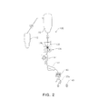
FIG. 2 is a view illustrating a bin (hopper) including a screw feeder and disposed in the lump iron ore manufacturing unit shown inFIG. 1 , the driving part sealing device of the embodiment of the present disclosure being installed on the screw feeder. -
FIG. 3 is a view illustrating the driving part sealing device installed on the screw feeder of the bin according to the embodiment of the present disclosure. -
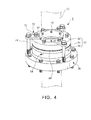
FIG. 4 is a perspective view illustrating an assembled state of the driving part sealing device according to the embodiment of the present disclosure. -
FIG. 5 is an exploded perspective view illustrating the driving part sealing device shown inFIG. 4 according to the embodiment of the present disclosure. -
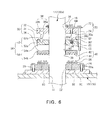
FIG. 6 is a cross-sectional view illustrating the driving part sealing device shown inFIG. 4 according to the embodiment of the present disclosure. - Hereinafter, embodiments of the present disclosure will be described with reference to the accompanying drawings.
-
FIGS. 1 to 3 are schematic views illustrating a molteniron producing apparatus 100 for producing molten iron using steam coal and fine iron ore. The molteniron producing apparatus 100 includes a lump ironore manufacturing unit 130, and a driving part sealing device 1 (refer to portion A ofFIG. 3 ) of the present disclosure is installed on ascrew feeder 136 of abin 138 of the lump ironore manufacturing unit 130. - For example, as shown in
FIG. 1 , the molteniron producing apparatus 100 for producing molten iron using steam coal and fine iron ore may include a plurality of reducingfurnaces 110, the lump ironore manufacturing unit 130, a lump ironore storage tank 150, and amelting furnace 170. The structure of the molteniron producing apparatus 100 is known in the related art. - As described above, iron reduced in the reducing
furnaces 110 is agglomerated intolumps 130a (refer toFIG. 2 ) in the lump ironore manufacturing unit 130 so as to improve gas permeability in themelting furnace 170. - As shown in
FIGS. 2 and3 , the lump ironore manufacturing unit 130 includes: astorage tank 132 into which fine iron ore reduced in the reducingfurnaces 110 is transferred by a pressure difference; anagglomeration machine 134 configured to agglomerate fine iron ore intolumps 130a by pressing the fine iron ore; thebin 138 disposed above theagglomeration machine 134 and including thescrew feeder 136 to uniformly feed fine iron ore to theagglomeration machine 134; and acrusher 140 configured tocrush lumps 130a into desired sizes. In the lump ironore manufacturing unit 130,iron ore lumps 130a are transferred from theagglomeration machine 134 to aconveyer 143 through adistributor 141 and ascreen 142. - Referring to
FIG. 1 , fine iron ore is transferred by a high-pressure gas within a temperature range of 600°C to 700°C along the reducingfurnaces 110, the lump ironore manufacturing unit 130, the lump ironore storage tank 150, and themelting furnace 170. - The lump iron
ore storage tank 150 temporarily stores iron ore lumps and supplies the iron ore lumps to themelting furnace 170. In addition, the molteniron producing apparatus 100 may further include adust collecting unit 190. -
FIG. 3 illustrates thebin 138 and theagglomeration machine 134. Thescrew feeder 136 is disposed in thebin 138. - The driving
part sealing device 1 is disposed in a structural part (for example, portion A inFIG. 3 ) of thebin 138 into which adriving shaft 136a of thescrew feeder 136 is inserted. The drivingpart sealing device 1 will be described in detail with reference toFIGS. 4 to 6 . - Since (fine) iron ore and steam coal are transferred in the molten
iron producing apparatus 100 by a difference in gas pressure, the drivingpart sealing device 1 of the embodiment of the present disclosure is disposed in a portion of thebin 138 into which the drivingshaft 136a of thescrew feeder 136 is inserted, so as to provide sealing against high-pressure and high-temperature environments. Particularly, the drivingpart sealing device 1 may absorb vibrations or shaking (chattering) of the drivingshaft 136a and may effectively absorb the rotations of the drivingshaft 136a to reduce wearing. - The driving
part sealing device 1 will now be described in more detail with reference toFIGS. 4 to 6 according to the embodiment of the present disclosure. - In the following description of the embodiment of the present disclosure given with reference to
FIGS. 1 to 3 , the drivingpart sealing device 1 is disposed on the drivingshaft 136a of thescrew feeder 136 installed in thebin 138 of the lump ironore manufacturing unit 130 of the molteniron producing apparatus 100 so as to seal thebin 138. However, the drivingpart sealing device 1 of the embodiment of the present disclosure is not limited thereto. - For example, the driving
part sealing device 1 may be used to seal a (airtight) container such as a bin or hopper into which a screw feeder is installed to uniformly discharge a stock such as powder or grain by using compressed air or gas. - The driving
part sealing device 1 of the embodiment of the present embodiment is not limited as being disposed on a driving shaft of a screw feeder. For example, the drivingpart sealing device 1 of the embodiment of the present disclosure may be disposed on a structural part of an airtight container into which a driving unit (driving shaft) is inserted, so as to seal an internal gas or powder atmosphere of the container. - That is, it may be understood that the driving
part sealing device 1 is used to seal astructure 10 in which a drivingpart 12 is disposed. In the following description, thestructure 10 is thebin 138, and the drivingpart 12 is the drivingshaft 136a of thescrew feeder 136. - Referring to
FIGS. 4 to 6 , the drivingpart sealing device 1 of the embodiment of the present disclosure may include: astructure mounting member 20 through which the drivingpart 12 shaped like a rod or pipe may be inserted; a drivingpart fixing member 30 placed on thestructure mounting member 20 to fix and seal the drivingpart 12 inserted thereinto; and arotation absorbing part 40 disposed between thestructure mounting member 20 and the drivingpart fixing member 30 to absorb the rotation of the drivingpart 12. - According to the embodiment of the present disclosure, the driving
part fixing member 30 is fixed to the drivingpart 12 inserted into thestructure 10 and is rotated together with the drivingpart 12 when the drivingpart 12 is rotated. Thestructure mounting member 20 is mounted on thestructure 10, and therotation absorbing part 40 is formed between thestructure mounting member 20 and the drivingpart fixing member 30 to absorb the rotation of the drivingpart 12 and the drivingpart fixing member 30 while providing stable sealing. Particularly, therotation absorbing part 40 has an alternating structure (described later in detail) for providing stable sealing while reducing abrasion. - According to the embodiment of the present disclosure, the
structure mounting member 20 of the drivingpart sealing device 1 is detachably mounted on thestructure 10 such as thebin 138 as shown inFIGS. 4 to 6 . Thestructure mounting member 20 may be a mounting ring having a drivingpart opening 22 through which the drivingpart 12 is inserted. - In the following description, the
structure mounting member 20 is taken as a structure mounting ring. - The
structure mounting ring 20 has a circular ring shape with the drivingpart opening 22, and the drivingpart 12 such as the drivingshaft 136a of thescrew feeder 136 is inserted into theopening 22 and a drivingpart opening 14 formed in thestructure 10. - A plurality of
bolt holes 20a are formed along the circumference of thestructure mounting ring 20, and thusbolts 24 may be inserted into the bolt holes 20a and coupled to a bracket or base 10a of thestructure 10 to detachably fix thestructure mounting ring 20 to thestructure 10. - As shown in
FIGS. 4 to 6 , the drivingpart fixing member 30 of the drivingpart sealing device 1 may include a plurality of driving part fixing rings by which rotational force can be transmitted through a rotation transmitting part 50 (described later). - In detail, for example, the driving
part fixing member 30 may include first, second, and third fixing rings 32, 34, and 36 sequentially arranged in a downward direction along the drivingpart 12. The number of the first to third fixing rings 32, 34, and 36 may be varied. - In the embodiment shown in
FIGS. 4 to 6 , the drivingpart fixing member 30 includes the first to third fixing rings 32, 34, and 36. However, thethird fixing ring 36 may not be used, or may be formed of a material different from a material used to form thestructure mounting ring 20. - For example, the first and second fixing rings 32 and 34 may be provided to install a vibration absorbing part 60 (described later). In addition, the second and third fixing rings 34 and 36 may be provided as a single part.
- If the
third fixing ring 36 is formed of the same material as that used to form thestructure mounting ring 20, when the drivingpart sealing device 1 of the embodiment is used in thebin 138 of the lump ironore manufacturing unit 130 of the molteniron producing apparatus 100 shown inFIGS. 1 to 3 , thethird fixing ring 36 and thestructure mounting ring 20 may be easily affected by a high temperature environment inside thebin 138 because thethird fixing ring 36 and thestructure mounting ring 20 have the same melting point. Therefore, thethird fixing ring 36 may be formed of a material capable of easily dissipating heat such as copper, and thestructure mounting ring 20 may be formed of a material different from the material of thethird fixing ring 36. In this case, the second and third fixing rings 34 and 36 may be provided as individual parts. - That is, in the embodiment of the present disclosure, the driving
part fixing member 30 may include the first and second fixing rings 32 and 34 in which thevibration absorbing part 60 is disposed, and may further include thethird fixing ring 36 formed of a material different from a material of thestructure mounting ring 20. - If the driving
part fixing member 30 includes only the first and second fixing rings 32 and 34, the rotation transmitting part 50 (described later in more detail) may include a firstrotation transmitting part 52, and if the drivingpart fixing member 30 includes all the first to third fixing rings 32, 34, and 36, therotation transmitting part 50 may include first and secondrotation transmitting parts - In other words, the driving
part fixing member 30 of the embodiment of the present disclosure may include only the first and second fixing rings 32 and 34 or all the first to third fixing rings 32, 34, and 36. - In the case in which the driving
part sealing device 1 is used for thebin 138 of the molteniron producing apparatus 100 shown inFIGS. 1 to 3 , the first to third fixing rings 32, 34, and 36 of the drivingpart fixing member 30 may include cooling structures for circulating a coolant. - The following description of the embodiment of the present disclosure will be given for the case in which the driving
part fixing member 30 includes all the first to third fixing rings 32, 34, and 34. - The first to third fixing rings 32, 34, and 36 are brought into contact with each other and are fixed. For example, the first and second fixing rings 32 and 34 or the first to third fixing rings 32, 34, and 36 are brought into contact with each other and assembled as shown in
FIG. 4 . In this state, fasteners such as setbolts 16 are inserted intoscrew holes 32b formed at regular intervals in a ridge of thefirst fixing ring 32 and fixed to the drivingpart 12 such as the drivingshaft 136a inserted into the first to third fixing rings 32, 34, and 36. - After the
first fixing ring 32 is fixed to the drivingpart 12, the first to third fixing rings 32, 34, and 36 are sequentially brought into contact with each other and assembled, and thethird fixing ring 36 is disposed on thestructure mounting ring 20. This contact state (assembled state) of thestructure mounting ring 20 and the first to third fixing rings (driving part fixing rings) 32, 34, and 36 may be maintained because the position of the drivingpart 12 such as the drivingshaft 136a is fixed in thestructure 10. - At this time, while inserting the driving
part 12 into thestructure 10, thestructure mounting ring 20 and the fixing rings 32, 34, and 36 of the drivingpart sealing device 1 may be easily assembled and mounted on thestructure 10 by using a clamping part 70 (to be described later). - As shown in
FIGS. 4 to 6 , in the embodiment of the present disclosure, therotation transmitting part 50 may include the firstrotation transmitting part 52, and the firstrotation transmitting part 52 may includepins 52b inserted intopin holes 52a formed in the first and second fixing rings 32 and 34 of the drivingpart fixing member 30. - In addition, the
rotation transmitting part 50 may include the secondrotation transmitting part 54, and the secondrotation transmitting part 54 may includeprotrusions 54a and recesses 54b formed at positions corresponding to those of the second and third fixing rings 34 and 36. - The number of the first and second
rotation transmitting parts rotation transmitting part 50 may include only one of the first and secondrotation transmitting parts - For example, if the driving
part fixing member 30 includes only the first and second fixing rings 32 and 34, therotation transmitting part 50 may include only one of the first and secondrotation transmitting parts vibration absorbing part 60 is considered, therotation transmitting part 50 may only include the firstrotation transmitting part 52 having a predetermined length. -
Penetration openings 38 are formed in inner center portions of the first to third fixing rings 32, 34 and 36 so that the drivingpart 12 such as the drivingshaft 136a may be inserted into thepenetration openings 38. - In the embodiment of the present disclosure, if the driving
part 12 to which thefirst fixing ring 32 is fixed using the setbolts 16 as shown inFIGS. 5 and6 is rotated, thefirst fixing ring 32 is rotated together with the drivingpart 12. At this time, the rotation of thefirst fixing ring 32 is transmitted to thesecond fixing ring 34 because thesecond fixing ring 34 is connected to thefirst fixing ring 32 through thepins 52b. - In addition, the rotation of the
second fixing ring 34 is also transmitted to thethird fixing ring 36 because theprotrusions 54a formed at regular intervals on the bottom side of thesecond fixing ring 34 are inserted into therecesses 54b formed on the topside of thethird fixing ring 36 as shown inFIGS. 5 and6 . - Therefore, as shown in
FIGS. 4 and6 , if the drivingpart 12 such as the drivingshaft 136a of thescrew feeder 136 is rotated, the rotation of the drivingpart 12 is sequentially transmitted to the first and second fixing rings 32 and 34 or the first to third fixing rings 34 and 36 of the drivingpart fixing member 30, and thus the drivingpart 12 and the drivingpart fixing member 30 may be rotated together. - In addition, a
guide groove 38a may be formed in the bottom side of thefirst fixing ring 32, and aguide ring 38b may be formed on the topside of thesecond fixing ring 34. Alternatively, stepped portions may be formed on edge portions of the first and second fixing rings 32 and 34 (a stepped portion 33 of thesecond fixing ring 34 is shown inFIG. 5 ). In addition, a packing 80' may be disposed between peripheral portions of the first and second fixing rings 32 and 34 to block contaminants such as dust. -
Sealing members 80 such as O-rings may be disposed in the penetration opening 38 of thethird fixing ring 36, and O-ring grooves 82 may be formed in thethird fixing ring 36 as shown inFIG. 5 . - Owing to the packing 80' disposed between the first and second fixing rings 32 and 34, the sealing
members 80 disposed between thethird fixing ring 36 and the drivingpart 12, and surface contact between the second and third fixing rings 34 and 36, sealing may be stably maintained to hermetically keep thestructure 10 without the leakage of high-pressure gas or dust from the inside of thestructure 10. - In addition, sealing
members 80 such as O-rings may be disposed between thestructure mounting ring 20 and the base (or bracket) 10a welded to thestructure 10. - As shown in
FIGS. 4 to 6 , in the drivingpart sealing device 1 of the embodiment of the present disclosure, thevibration absorbing part 60 may be disposed between at least the first and second fixing rings 32 and 34 of the first to third fixing rings 34 and 36 so as to absorb vibrations or shaking while the drivingpart 12 is rotated. - For example, the
vibration absorbing part 60 may include a plurality of coil springs arranged along the circumference of thesecond fixing ring 34. - In addition, the
vibration absorbing part 60 may includesupport plates 60a fixed to the topsides of the coil springs, and the elasticity of the coil springs may be adjusted by usingpressing bolts 64 inserted intocoupling holes 32c formed at regular intervals along the circumference of thefirst fixing ring 32. - That is, the elasticity of the coil springs may be adjusted by tightening or loosening the
pressing bolts 64, so as to control vibration (shaking) absorbing ability of the first and second fixing rings 32 and 34. - For example, when the driving
part 12 such as the drivingshaft 136a of thescrew feeder 136 installed in thebin 138 is rotated as shown inFIG. 3 , fine iron ore may be discharged from thebin 138 by the rotation of thescrew feeder 136, and while the fine iron ore is discharged, the drivingshaft 136a may be vibrated (shaken). At this time, the coil springs of thevibration absorbing part 60 disposed between the first and second fixing rings 32 and 34 may absorb the vibrations. Therefore, problems of the related art such as vibration or sealing errors caused by vibration may be prevented. That is, the drivingpart sealing device 1 of the embodiment of the present disclosure may effectively prevent sealing errors caused by vibration of a driving shaft or may effectively protect a driving shaft or a structure. - As shown in
FIGS. 4 and5 , the drivingpart sealing device 1 of the embodiment of the present disclosure may further include the clampingpart 70. The clampingpart 70 may be used to maintain the assembled state of thestructure mounting ring 20 and the first to third fixing rings 34 and 36 of the drivingpart fixing member 30 when the drivingpart sealing device 1 is installed on thestructure 10. In addition, since the clampingpart 70 fixes thefirst fixing ring 32 to the drivingpart 12, the drivingpart sealing device 1 may be easily installed on thestructure 10. - For example, the clamping
part 70 may be coupled between the drivingpart fixing member 30 and thestructure mounting ring 20 to be mounted on thestructure 10 to maintain the assembled state of the drivingpart sealing device 1 until thefirst fixing ring 32 is fixed to the drivingpart 12. - The clamping
part 70 may include: horizontally extending clamping members (bars) 72 coupled to some of thepressing bolts 64 fixed to thefirst fixing ring 32; and clampingbolts 74 inserted into ends of the clampingmembers 72 and vertically coupled to the structure mounting ring 20 (or the structure 10). - The clamping
bolts 74 inserted into the clampingmembers 72 may be screwed in thestructure mounting ring 20, and the clampingmembers 72 may be fixed to thefirst fixing ring 32 by thepressing bolts 64. Therefore, the first to third fixing rings 34 and 36 may be clamped to thestructure mounting ring 20 in a tightly contact (assembled) state. - After the driving
part sealing device 1 is installed on the structure 10 (in this state, the drivingpart 12 protrudes from thestructure 10 through the drivingpart sealing device 1, and thefirst fixing ring 32 is fixed to the drivingpart 12 using the set bolts 16), the clampingpart 70 may be easily detached from the drivingpart sealing device 1 by separating the clampingmembers 72 after slightly loosening thepressing bolts 64 and unscrewing the clampingbolts 74. - Next, as shown in
FIGS. 5 and6 , therotation absorbing part 40 of the drivingpart sealing device 1 may include one or moreconvex rings 42 and one or more concave rings 44 that are alternately arranged at corresponding positions on the bottom side of thethird fixing ring 36 of the drivingpart fixing member 30 and the topside of thestructure mounting ring 20, so that the rotation of thethird fixing ring 36 may not be transmitted to thestructure mounting ring 20. - The convex rings 42 and the concave rings 44 may be rings and grooves in which the rings are insertable, and rotation may not be transmitted therebetween.
- In the embodiment of the present disclosure, the terms "convex rings" and "concave rings" are used to denote alternately insertable structures. Referring to an actual structure shown in
FIG. 6 , rings are arranged at predetermined intervals on the bottom side of thethird fixing ring 36 in one piece with thethird fixing ring 36, and rings are arranged at predetermined intervals on acentral projection 26 of thestructure mounting ring 20 in one piece with thecentral projection 26. - Since the
convex rings 42 formed on the bottom side of thethird fixing ring 36 are separate from the concave rings 44 formed on the topside of the structure mounting member (ring) 20, rotation may not be transmitted therebetween. In addition, since theconvex rings 42 and the concave rings 44 are sequentially arranged in radial directions with regard to thethird fixing ring 36 and thestructure mounting ring 20, sealing between theconvex rings 42 and the concave rings 44 may be reliable. - As shown in
FIGS. 5 and6 , therotation absorbing part 40 may include at least one of alubricant supply inlet 90 and agas supply inlet 92 in thecentral projection 26 of the structure mounting ring 20 (thelubricant supply inlet 90 may be favored), so as to reduce friction between theconvex rings 42 and the concave rings 44 and improve sealing. - Referring to
FIG. 6 , a lubricant such as grease may be supplied through thelubricant supply inlet 90 to an innermost region between theconvex rings 42 and the concave rings 44, and then the lubricant be smoothly distributed to the outermostconvex ring 42 and concave ring 44 by pressure. - In this way, the lubricant such as grease may be uniformly distributed between the
convex rings 42 and the concave rings 44 of therotation absorbing part 40, and thus the interface between theconvex rings 42 and the concave rings 44 may be sealed. In addition, theconvex rings 42 and the concave rings 44 may be worn or damaged less when the drivingpart 12 rotates. - In this way, the lubricant such as grease may block a gap between the
convex rings 42 and the concave rings 44 of therotation absorbing part 40 for sealing therebetween. - Along with this, inert gas such as nitrogen gas may be supplied through the
gas supply inlet 92 to form a gas curtain layer for effectively preventing the leakage of gas or dust. - In addition, as shown in
FIG. 6 , when thestructure mounting ring 20 of the embodiment of the present disclosure is mounted on the structure 10 (such as the bin 138) or the base 10a attached to an outer wall of thebin 138, the sealingmembers 80 may be disposed between the lowermost fixing ring of the driving part fixing member 30 (that is, the second or third fixingring 34 or 36) and thestructure 10 or the base 10a. In this way, a gap between metal plates may be sealed. - An aspect of the present disclosure provides a driving part sealing device capable of absorbing vibration (shaking) and effectively sealing a structure such as a bin or hopper through which a driving shaft (of a screw feeder) is inserted. In addition, alternating ring structures additionally included in the driving part sealing device may prevent transmission of rotation and may provide improved sealing while reducing abrasion.
Claims (15)
- A sealing device for a driving part, the sealing device comprising:a structure mounting member mounted on a structure and receiving the driving part therein;a driving part fixing member disposed on the structure mounting member and fixed to the driving part for sealing the driving part inserted thereinto; anda rotation absorbing part provided between the driving part fixing member and the structure mounting member for absorbing rotation using a relational structure.
- The sealing device of claim 1, wherein the structure mounting member is a structure mounting ring coupled to the structure.
- The sealing device of claim 1, wherein the driving part fixing member comprises a plurality of driving part fixing rings assembled to transmit rotational force through a rotation transmitting part.
- The sealing device of claim 3, wherein the rotation transmitting part comprises at least one of:a first rotation transmitting part comprising a pin inserted into at least one pin hole formed in the driving part fixing rings; anda second rotation transmitting part comprising a protrusion inserted into at least one recess formed in the driving part fixing rings.
- The sealing device of claim 4, wherein the first and second rotation transmitting parts are sequentially arranged on the driving part fixing rings.
- The sealing device of claim 3, further comprising a guide groove and a guide ring provided on the driving part fixing rings, or stepped portions formed on edge portions of the driving part fixing rings making contact with each other.
- The sealing device of any one of claims 1 to 6, wherein the rotation absorbing part comprises rings arranged alternately on the driving part fixing member and the structure mounting member so as to absorb rotation of the driving part.
- The sealing device of claim 7, wherein the rings of the rotation absorbing part comprise at least one convex ring and at least one concave ring arranged at corresponding positions, and
the convex ring and the concave ring are correspondingly arranged on one of the driving part fixing rings of the driving part fixing member and a structure mounting ring, the structure mounting ring being the structure mounting member and adjacent to the driving part fixing ring. - The sealing device of claim 3, further comprising a vibration absorbing part disposed between the driving part fixing rings to absorb vibrations or shaking when the driving part is rotated.
- The sealing device of claim 9, wherein the vibration absorbing part is a coil spring disposed in a hole formed in the driving part fixing rings, and the coil spring is adjusted in elasticity by using a pressing bolt inserted into the driving part fixing rings.
- The sealing device of any one of claims 1 to 6, further comprising a clamping part connected between the driving part fixing member and the structure mounting member or the structure for being used when the sealing device is installed on the structure.
- The sealing device of claim 11, wherein the clamping part comprises:a clamping bar horizontally fixed to an upper side of the driving part fixing member; anda clamping bolt inserted into the clamping bar and coupled to the clamping bar and the structure mounting member or the structure.
- The sealing device of any one of claims 1 to 6, wherein a fastener fixed to the driving part is coupled to at least one of the driving part fixing rings of the driving part fixing member, and
at least one sealing member is provided on at least one of the structure mounting member and the driving part fixing member for sealing between the driving part and the sealing device. - The sealing device of any one of claims 1 to 6, further comprising at least one of a lubricant supply unit and a gas supply unit connected to the rotation absorbing part for suppressing abrasion or maintaining sealing.
- The sealing device of any one of claims 1 to 6, wherein the structure is a bin or hopper comprising a screw feeder, and
the driving part is a driving shaft of the screw feeder.
Applications Claiming Priority (2)
| Application Number | Priority Date | Filing Date | Title |
|---|---|---|---|
| KR1020110124863A KR101304791B1 (en) | 2011-11-28 | 2011-11-28 | Device for Sealing Driving Shaft |
| PCT/KR2012/010109 WO2013081350A1 (en) | 2011-11-28 | 2012-11-27 | Sealing device of driving section |
Publications (3)
| Publication Number | Publication Date |
|---|---|
| EP2787091A1 true EP2787091A1 (en) | 2014-10-08 |
| EP2787091A4 EP2787091A4 (en) | 2015-08-05 |
| EP2787091B1 EP2787091B1 (en) | 2017-07-26 |
Family
ID=48535744
Family Applications (1)
| Application Number | Title | Priority Date | Filing Date |
|---|---|---|---|
| EP12853778.4A Active EP2787091B1 (en) | 2011-11-28 | 2012-11-27 | Sealing device of driving section |
Country Status (4)
| Country | Link |
|---|---|
| EP (1) | EP2787091B1 (en) |
| KR (1) | KR101304791B1 (en) |
| CN (1) | CN103975083B (en) |
| WO (1) | WO2013081350A1 (en) |
Families Citing this family (5)
| Publication number | Priority date | Publication date | Assignee | Title |
|---|---|---|---|---|
| US9957447B2 (en) * | 2015-12-22 | 2018-05-01 | Cameron Solutions, Inc. | Electrostatic technology system and process to dehydrate crude oil in a crude oil storage tank of a floating production storage and offloading installation |
| US11220635B2 (en) * | 2017-04-07 | 2022-01-11 | Schmidt + Clemens Gmbh + Co. Kg | Pipe and device for thermally cleaving hydrocarbons |
| KR102362800B1 (en) * | 2021-04-26 | 2022-02-15 | (주)에코크레이션 | Apparatus for restoring waste plastic to oil |
| KR200496606Y1 (en) * | 2022-11-01 | 2023-03-10 | 한전케이피에스 주식회사 | Sealing device for 1st wicket gate housing |
| KR102795954B1 (en) * | 2023-12-20 | 2025-04-16 | (주)에코크레이션 | Airtight device for waste plastic restore system |
Family Cites Families (16)
| Publication number | Priority date | Publication date | Assignee | Title |
|---|---|---|---|---|
| AT404735B (en) | 1992-10-22 | 1999-02-25 | Voest Alpine Ind Anlagen | METHOD AND INSTALLATION FOR THE PRODUCTION OF LIQUID PIPE IRON OR LIQUID STEEL PRE-PRODUCTS |
| US5666638A (en) | 1993-09-30 | 1997-09-09 | Maschinenfabrik Koppern Gmbh & Co. Kg | Process for producing sponge iron briquettes from fine ore |
| JPH08104416A (en) * | 1994-10-04 | 1996-04-23 | Mitsubishi Heavy Ind Ltd | Screw feeder |
| JPH08104415A (en) * | 1994-10-04 | 1996-04-23 | Mitsubishi Heavy Ind Ltd | Screw feeder |
| JPH08156888A (en) * | 1994-12-09 | 1996-06-18 | Kiipaa Kk | Shaft sealing device for ship propeller shaft |
| CN2229580Y (en) * | 1995-08-24 | 1996-06-19 | 朱雨秀 | Double-buffer structure rotary axle end-face sealing apparatus |
| CN2280154Y (en) * | 1996-12-12 | 1998-04-29 | 张家港市钻机厂 | Main shaft sealing device of built-in type in drilling machine |
| KR100356502B1 (en) * | 2000-01-31 | 2002-10-18 | 주식회사 신원기계부품 | A sealing devices for axis of rotation material |
| JP2003227570A (en) * | 2002-02-05 | 2003-08-15 | Sumitomo Heavy Ind Ltd | Shaft sealing device |
| KR100496990B1 (en) * | 2003-04-11 | 2005-06-23 | 주식회사 신원기계부품 | a sealing unit for a rotary device |
| KR200354025Y1 (en) * | 2004-03-09 | 2004-06-23 | 홍지호 | axis sealing apparatus for a pump |
| KR100709960B1 (en) * | 2004-12-17 | 2007-04-25 | 심선희 | Mechanical seal |
| JP2008240837A (en) * | 2007-03-27 | 2008-10-09 | Kubota Corp | Mechanical seal device |
| CN201363424Y (en) * | 2009-02-20 | 2009-12-16 | 上海世邦机器有限公司 | Vertical shaft sealing device of vertical shaft impact crusher |
| CN201461527U (en) * | 2009-08-21 | 2010-05-12 | 石家庄强大密封有限公司 | Immobile compensation type pump shaft sealing device |
| KR101044346B1 (en) * | 2010-12-07 | 2011-06-29 | 박영섭 | Stern Tube Sealing Device |
-
2011
- 2011-11-28 KR KR1020110124863A patent/KR101304791B1/en active Active
-
2012
- 2012-11-27 WO PCT/KR2012/010109 patent/WO2013081350A1/en not_active Ceased
- 2012-11-27 CN CN201280058579.6A patent/CN103975083B/en active Active
- 2012-11-27 EP EP12853778.4A patent/EP2787091B1/en active Active
Also Published As
| Publication number | Publication date |
|---|---|
| CN103975083B (en) | 2016-04-06 |
| KR101304791B1 (en) | 2013-09-05 |
| EP2787091B1 (en) | 2017-07-26 |
| CN103975083A (en) | 2014-08-06 |
| EP2787091A4 (en) | 2015-08-05 |
| KR20130058876A (en) | 2013-06-05 |
| WO2013081350A1 (en) | 2013-06-06 |
Similar Documents
| Publication | Publication Date | Title |
|---|---|---|
| EP2787091B1 (en) | Sealing device of driving section | |
| RU2219244C2 (en) | System of unloading of iron produced by a method of its direct reduction | |
| JPH06292835A (en) | Roller mill | |
| WO2021243912A1 (en) | Material conveying device | |
| CN102296133A (en) | Feeding device for receiving tank of blast furnace | |
| JP6331607B2 (en) | How to charge the bellless blast furnace | |
| EP1178276A2 (en) | Discharge apparatus for movable hearth type heat-treatment furnace, its operation method, and method and apparatus for manufacturing molten iron using the same | |
| CN103127883B (en) | Heat treatment apparatus for powder material | |
| EP2749530A1 (en) | Calcium carbide granules, process for producing calcium carbide granules, and system for producing calcium carbide granules | |
| US6544468B1 (en) | Method for cooling a shaft furnace loading device | |
| KR20140062227A (en) | Ceramic chute liner and manufacturing method thereof | |
| JP2017020092A (en) | Seal mechanism and blast furnace | |
| CN1842606B (en) | Apparatus for manufacturing compacted irons of reduced materials containing fine direct reduced irons and apparatus for manufacturing molten irons using the same | |
| CN104399565A (en) | High-low-high split type lining board for semi-autogenous mill barrel and operation method | |
| WO2022128725A1 (en) | Screw flight system, replacement kit, a vertical grinding mill, and method of mounting the same | |
| JP2009068721A (en) | Sealing device for sinter cooler | |
| RU2354721C2 (en) | Unit for manufacturing of compressed iron from recycled materials, containing fine-grained directly reduced iron, and facility for manufacturing of molten cast iron, in which this facility is used | |
| EP2479295B1 (en) | Apparatus for manufacturing compacted iron, and apparatus for manufacturing molten iron comprising the apparatus | |
| EP1877715B1 (en) | Means for conveying material | |
| EP0656516B1 (en) | Alloy material addition method and apparatus for smelting and melting furnaces | |
| JP2014201747A (en) | Furnace top bunker of bell-less type blast furnace | |
| KR101419391B1 (en) | Blast furnace having temporary tapping hole and method of performing iron tapping of blast furnace using the same | |
| EP2586877B1 (en) | Furnace having even distribution of gas | |
| KR101853766B1 (en) | Material Feeding Apparatus | |
| JP5884158B2 (en) | Protective structure for contact surface of powdered mass |
Legal Events
| Date | Code | Title | Description |
|---|---|---|---|
| PUAI | Public reference made under article 153(3) epc to a published international application that has entered the european phase |
Free format text: ORIGINAL CODE: 0009012 |
|
| 17P | Request for examination filed |
Effective date: 20140625 |
|
| AK | Designated contracting states |
Kind code of ref document: A1 Designated state(s): AL AT BE BG CH CY CZ DE DK EE ES FI FR GB GR HR HU IE IS IT LI LT LU LV MC MK MT NL NO PL PT RO RS SE SI SK SM TR |
|
| RIN1 | Information on inventor provided before grant (corrected) |
Inventor name: CHO, MYUNG-HO Inventor name: CHOI, SEUNG-HO Inventor name: JEON, SANG-JIN |
|
| DAX | Request for extension of the european patent (deleted) | ||
| RA4 | Supplementary search report drawn up and despatched (corrected) |
Effective date: 20150708 |
|
| RIC1 | Information provided on ipc code assigned before grant |
Ipc: C22B 1/16 20060101AFI20150702BHEP Ipc: F27B 21/08 20060101ALI20150702BHEP |
|
| GRAP | Despatch of communication of intention to grant a patent |
Free format text: ORIGINAL CODE: EPIDOSNIGR1 |
|
| STAA | Information on the status of an ep patent application or granted ep patent |
Free format text: STATUS: GRANT OF PATENT IS INTENDED |
|
| INTG | Intention to grant announced |
Effective date: 20161109 |
|
| RIN1 | Information on inventor provided before grant (corrected) |
Inventor name: JEON, SANG-JIN Inventor name: CHOI, SEUNG-HO Inventor name: CHO, MYUNG-HO |
|
| GRAS | Grant fee paid |
Free format text: ORIGINAL CODE: EPIDOSNIGR3 |
|
| GRAJ | Information related to disapproval of communication of intention to grant by the applicant or resumption of examination proceedings by the epo deleted |
Free format text: ORIGINAL CODE: EPIDOSDIGR1 |
|
| GRAL | Information related to payment of fee for publishing/printing deleted |
Free format text: ORIGINAL CODE: EPIDOSDIGR3 |
|
| STAA | Information on the status of an ep patent application or granted ep patent |
Free format text: STATUS: REQUEST FOR EXAMINATION WAS MADE |
|
| RAP1 | Party data changed (applicant data changed or rights of an application transferred) |
Owner name: POSCO |
|
| INTC | Intention to grant announced (deleted) | ||
| GRAR | Information related to intention to grant a patent recorded |
Free format text: ORIGINAL CODE: EPIDOSNIGR71 |
|
| STAA | Information on the status of an ep patent application or granted ep patent |
Free format text: STATUS: GRANT OF PATENT IS INTENDED |
|
| GRAA | (expected) grant |
Free format text: ORIGINAL CODE: 0009210 |
|
| STAA | Information on the status of an ep patent application or granted ep patent |
Free format text: STATUS: THE PATENT HAS BEEN GRANTED |
|
| AK | Designated contracting states |
Kind code of ref document: B1 Designated state(s): AL AT BE BG CH CY CZ DE DK EE ES FI FR GB GR HR HU IE IS IT LI LT LU LV MC MK MT NL NO PL PT RO RS SE SI SK SM TR |
|
| INTG | Intention to grant announced |
Effective date: 20170616 |
|
| REG | Reference to a national code |
Ref country code: GB Ref legal event code: FG4D |
|
| REG | Reference to a national code |
Ref country code: CH Ref legal event code: EP |
|
| REG | Reference to a national code |
Ref country code: AT Ref legal event code: REF Ref document number: 912456 Country of ref document: AT Kind code of ref document: T Effective date: 20170815 |
|
| REG | Reference to a national code |
Ref country code: IE Ref legal event code: FG4D |
|
| REG | Reference to a national code |
Ref country code: DE Ref legal event code: R096 Ref document number: 602012035151 Country of ref document: DE |
|
| REG | Reference to a national code |
Ref country code: FR Ref legal event code: PLFP Year of fee payment: 6 |
|
| REG | Reference to a national code |
Ref country code: NL Ref legal event code: MP Effective date: 20170726 |
|
| REG | Reference to a national code |
Ref country code: LT Ref legal event code: MG4D |
|
| REG | Reference to a national code |
Ref country code: AT Ref legal event code: MK05 Ref document number: 912456 Country of ref document: AT Kind code of ref document: T Effective date: 20170726 |
|
| PG25 | Lapsed in a contracting state [announced via postgrant information from national office to epo] |
Ref country code: NL Free format text: LAPSE BECAUSE OF FAILURE TO SUBMIT A TRANSLATION OF THE DESCRIPTION OR TO PAY THE FEE WITHIN THE PRESCRIBED TIME-LIMIT Effective date: 20170726 Ref country code: HR Free format text: LAPSE BECAUSE OF FAILURE TO SUBMIT A TRANSLATION OF THE DESCRIPTION OR TO PAY THE FEE WITHIN THE PRESCRIBED TIME-LIMIT Effective date: 20170726 Ref country code: NO Free format text: LAPSE BECAUSE OF FAILURE TO SUBMIT A TRANSLATION OF THE DESCRIPTION OR TO PAY THE FEE WITHIN THE PRESCRIBED TIME-LIMIT Effective date: 20171026 Ref country code: FI Free format text: LAPSE BECAUSE OF FAILURE TO SUBMIT A TRANSLATION OF THE DESCRIPTION OR TO PAY THE FEE WITHIN THE PRESCRIBED TIME-LIMIT Effective date: 20170726 Ref country code: SE Free format text: LAPSE BECAUSE OF FAILURE TO SUBMIT A TRANSLATION OF THE DESCRIPTION OR TO PAY THE FEE WITHIN THE PRESCRIBED TIME-LIMIT Effective date: 20170726 Ref country code: LT Free format text: LAPSE BECAUSE OF FAILURE TO SUBMIT A TRANSLATION OF THE DESCRIPTION OR TO PAY THE FEE WITHIN THE PRESCRIBED TIME-LIMIT Effective date: 20170726 Ref country code: AT Free format text: LAPSE BECAUSE OF FAILURE TO SUBMIT A TRANSLATION OF THE DESCRIPTION OR TO PAY THE FEE WITHIN THE PRESCRIBED TIME-LIMIT Effective date: 20170726 |
|
| PG25 | Lapsed in a contracting state [announced via postgrant information from national office to epo] |
Ref country code: RS Free format text: LAPSE BECAUSE OF FAILURE TO SUBMIT A TRANSLATION OF THE DESCRIPTION OR TO PAY THE FEE WITHIN THE PRESCRIBED TIME-LIMIT Effective date: 20170726 Ref country code: LV Free format text: LAPSE BECAUSE OF FAILURE TO SUBMIT A TRANSLATION OF THE DESCRIPTION OR TO PAY THE FEE WITHIN THE PRESCRIBED TIME-LIMIT Effective date: 20170726 Ref country code: GR Free format text: LAPSE BECAUSE OF FAILURE TO SUBMIT A TRANSLATION OF THE DESCRIPTION OR TO PAY THE FEE WITHIN THE PRESCRIBED TIME-LIMIT Effective date: 20171027 Ref country code: BG Free format text: LAPSE BECAUSE OF FAILURE TO SUBMIT A TRANSLATION OF THE DESCRIPTION OR TO PAY THE FEE WITHIN THE PRESCRIBED TIME-LIMIT Effective date: 20171026 Ref country code: PL Free format text: LAPSE BECAUSE OF FAILURE TO SUBMIT A TRANSLATION OF THE DESCRIPTION OR TO PAY THE FEE WITHIN THE PRESCRIBED TIME-LIMIT Effective date: 20170726 Ref country code: ES Free format text: LAPSE BECAUSE OF FAILURE TO SUBMIT A TRANSLATION OF THE DESCRIPTION OR TO PAY THE FEE WITHIN THE PRESCRIBED TIME-LIMIT Effective date: 20170726 Ref country code: IS Free format text: LAPSE BECAUSE OF FAILURE TO SUBMIT A TRANSLATION OF THE DESCRIPTION OR TO PAY THE FEE WITHIN THE PRESCRIBED TIME-LIMIT Effective date: 20171126 |
|
| PG25 | Lapsed in a contracting state [announced via postgrant information from national office to epo] |
Ref country code: RO Free format text: LAPSE BECAUSE OF FAILURE TO SUBMIT A TRANSLATION OF THE DESCRIPTION OR TO PAY THE FEE WITHIN THE PRESCRIBED TIME-LIMIT Effective date: 20170726 Ref country code: CZ Free format text: LAPSE BECAUSE OF FAILURE TO SUBMIT A TRANSLATION OF THE DESCRIPTION OR TO PAY THE FEE WITHIN THE PRESCRIBED TIME-LIMIT Effective date: 20170726 Ref country code: DK Free format text: LAPSE BECAUSE OF FAILURE TO SUBMIT A TRANSLATION OF THE DESCRIPTION OR TO PAY THE FEE WITHIN THE PRESCRIBED TIME-LIMIT Effective date: 20170726 |
|
| REG | Reference to a national code |
Ref country code: DE Ref legal event code: R097 Ref document number: 602012035151 Country of ref document: DE |
|
| PG25 | Lapsed in a contracting state [announced via postgrant information from national office to epo] |
Ref country code: IT Free format text: LAPSE BECAUSE OF FAILURE TO SUBMIT A TRANSLATION OF THE DESCRIPTION OR TO PAY THE FEE WITHIN THE PRESCRIBED TIME-LIMIT Effective date: 20170726 Ref country code: EE Free format text: LAPSE BECAUSE OF FAILURE TO SUBMIT A TRANSLATION OF THE DESCRIPTION OR TO PAY THE FEE WITHIN THE PRESCRIBED TIME-LIMIT Effective date: 20170726 Ref country code: SK Free format text: LAPSE BECAUSE OF FAILURE TO SUBMIT A TRANSLATION OF THE DESCRIPTION OR TO PAY THE FEE WITHIN THE PRESCRIBED TIME-LIMIT Effective date: 20170726 Ref country code: SM Free format text: LAPSE BECAUSE OF FAILURE TO SUBMIT A TRANSLATION OF THE DESCRIPTION OR TO PAY THE FEE WITHIN THE PRESCRIBED TIME-LIMIT Effective date: 20170726 |
|
| PLBE | No opposition filed within time limit |
Free format text: ORIGINAL CODE: 0009261 |
|
| STAA | Information on the status of an ep patent application or granted ep patent |
Free format text: STATUS: NO OPPOSITION FILED WITHIN TIME LIMIT |
|
| PG25 | Lapsed in a contracting state [announced via postgrant information from national office to epo] |
Ref country code: MC Free format text: LAPSE BECAUSE OF FAILURE TO SUBMIT A TRANSLATION OF THE DESCRIPTION OR TO PAY THE FEE WITHIN THE PRESCRIBED TIME-LIMIT Effective date: 20170726 |
|
| 26N | No opposition filed |
Effective date: 20180430 |
|
| GBPC | Gb: european patent ceased through non-payment of renewal fee |
Effective date: 20171127 |
|
| PG25 | Lapsed in a contracting state [announced via postgrant information from national office to epo] |
Ref country code: LI Free format text: LAPSE BECAUSE OF NON-PAYMENT OF DUE FEES Effective date: 20171130 Ref country code: CH Free format text: LAPSE BECAUSE OF NON-PAYMENT OF DUE FEES Effective date: 20171130 |
|
| PG25 | Lapsed in a contracting state [announced via postgrant information from national office to epo] |
Ref country code: SI Free format text: LAPSE BECAUSE OF FAILURE TO SUBMIT A TRANSLATION OF THE DESCRIPTION OR TO PAY THE FEE WITHIN THE PRESCRIBED TIME-LIMIT Effective date: 20170726 Ref country code: LU Free format text: LAPSE BECAUSE OF NON-PAYMENT OF DUE FEES Effective date: 20171127 |
|
| REG | Reference to a national code |
Ref country code: BE Ref legal event code: MM Effective date: 20171130 |
|
| REG | Reference to a national code |
Ref country code: IE Ref legal event code: MM4A |
|
| PG25 | Lapsed in a contracting state [announced via postgrant information from national office to epo] |
Ref country code: MT Free format text: LAPSE BECAUSE OF NON-PAYMENT OF DUE FEES Effective date: 20171127 |
|
| PG25 | Lapsed in a contracting state [announced via postgrant information from national office to epo] |
Ref country code: IE Free format text: LAPSE BECAUSE OF NON-PAYMENT OF DUE FEES Effective date: 20171127 |
|
| PG25 | Lapsed in a contracting state [announced via postgrant information from national office to epo] |
Ref country code: BE Free format text: LAPSE BECAUSE OF NON-PAYMENT OF DUE FEES Effective date: 20171130 Ref country code: GB Free format text: LAPSE BECAUSE OF NON-PAYMENT OF DUE FEES Effective date: 20171127 |
|
| PG25 | Lapsed in a contracting state [announced via postgrant information from national office to epo] |
Ref country code: HU Free format text: LAPSE BECAUSE OF FAILURE TO SUBMIT A TRANSLATION OF THE DESCRIPTION OR TO PAY THE FEE WITHIN THE PRESCRIBED TIME-LIMIT; INVALID AB INITIO Effective date: 20121127 |
|
| PG25 | Lapsed in a contracting state [announced via postgrant information from national office to epo] |
Ref country code: CY Free format text: LAPSE BECAUSE OF FAILURE TO SUBMIT A TRANSLATION OF THE DESCRIPTION OR TO PAY THE FEE WITHIN THE PRESCRIBED TIME-LIMIT Effective date: 20170726 |
|
| PG25 | Lapsed in a contracting state [announced via postgrant information from national office to epo] |
Ref country code: MK Free format text: LAPSE BECAUSE OF FAILURE TO SUBMIT A TRANSLATION OF THE DESCRIPTION OR TO PAY THE FEE WITHIN THE PRESCRIBED TIME-LIMIT Effective date: 20170726 |
|
| PG25 | Lapsed in a contracting state [announced via postgrant information from national office to epo] |
Ref country code: TR Free format text: LAPSE BECAUSE OF FAILURE TO SUBMIT A TRANSLATION OF THE DESCRIPTION OR TO PAY THE FEE WITHIN THE PRESCRIBED TIME-LIMIT Effective date: 20170726 |
|
| PG25 | Lapsed in a contracting state [announced via postgrant information from national office to epo] |
Ref country code: PT Free format text: LAPSE BECAUSE OF FAILURE TO SUBMIT A TRANSLATION OF THE DESCRIPTION OR TO PAY THE FEE WITHIN THE PRESCRIBED TIME-LIMIT Effective date: 20170726 |
|
| PG25 | Lapsed in a contracting state [announced via postgrant information from national office to epo] |
Ref country code: AL Free format text: LAPSE BECAUSE OF FAILURE TO SUBMIT A TRANSLATION OF THE DESCRIPTION OR TO PAY THE FEE WITHIN THE PRESCRIBED TIME-LIMIT Effective date: 20170726 |
|
| REG | Reference to a national code |
Ref country code: DE Ref legal event code: R081 Ref document number: 602012035151 Country of ref document: DE Owner name: POSCO CO., LTD, POHANG-SI, KR Free format text: FORMER OWNER: POSCO, POHANG-SI, GYEONGSANGBUK-DO, KR Ref country code: DE Ref legal event code: R081 Ref document number: 602012035151 Country of ref document: DE Owner name: POSCO CO., LTD, POHANG- SI, KR Free format text: FORMER OWNER: POSCO, POHANG-SI, GYEONGSANGBUK-DO, KR Ref country code: DE Ref legal event code: R081 Ref document number: 602012035151 Country of ref document: DE Owner name: POSCO HOLDINGS INC., KR Free format text: FORMER OWNER: POSCO, POHANG-SI, GYEONGSANGBUK-DO, KR |
|
| REG | Reference to a national code |
Ref country code: DE Ref legal event code: R081 Ref document number: 602012035151 Country of ref document: DE Owner name: POSCO CO., LTD, POHANG-SI, KR Free format text: FORMER OWNER: POSCO HOLDINGS INC., SEOUL, KR Ref country code: DE Ref legal event code: R081 Ref document number: 602012035151 Country of ref document: DE Owner name: POSCO CO., LTD, POHANG- SI, KR Free format text: FORMER OWNER: POSCO HOLDINGS INC., SEOUL, KR |
|
| PGFP | Annual fee paid to national office [announced via postgrant information from national office to epo] |
Ref country code: FR Payment date: 20250925 Year of fee payment: 14 |
|
| PGFP | Annual fee paid to national office [announced via postgrant information from national office to epo] |
Ref country code: DE Payment date: 20250922 Year of fee payment: 14 |