EP2786935A1 - Ram air channel assembly and method for operating a ram air channel assembly - Google Patents
Ram air channel assembly and method for operating a ram air channel assembly Download PDFInfo
- Publication number
- EP2786935A1 EP2786935A1 EP13161947.0A EP13161947A EP2786935A1 EP 2786935 A1 EP2786935 A1 EP 2786935A1 EP 13161947 A EP13161947 A EP 13161947A EP 2786935 A1 EP2786935 A1 EP 2786935A1
- Authority
- EP
- European Patent Office
- Prior art keywords
- ram air
- air inlet
- section
- aircraft
- outer skin
- Prior art date
- Legal status (The legal status is an assumption and is not a legal conclusion. Google has not performed a legal analysis and makes no representation as to the accuracy of the status listed.)
- Granted
Links
- 238000000034 method Methods 0.000 title claims description 7
- 238000011144 upstream manufacturing Methods 0.000 claims abstract description 11
- 239000003570 air Substances 0.000 claims description 395
- 239000012080 ambient air Substances 0.000 claims description 19
- 238000004378 air conditioning Methods 0.000 claims description 9
- 230000006641 stabilisation Effects 0.000 claims description 9
- 238000011105 stabilization Methods 0.000 claims description 9
- 238000009423 ventilation Methods 0.000 claims description 8
- 238000006073 displacement reaction Methods 0.000 description 7
- 238000001816 cooling Methods 0.000 description 2
- 230000008878 coupling Effects 0.000 description 2
- 238000010168 coupling process Methods 0.000 description 2
- 238000005859 coupling reaction Methods 0.000 description 2
- 230000000712 assembly Effects 0.000 description 1
- 238000000429 assembly Methods 0.000 description 1
- QVGXLLKOCUKJST-UHFFFAOYSA-N atomic oxygen Chemical compound [O] QVGXLLKOCUKJST-UHFFFAOYSA-N 0.000 description 1
- 230000005662 electromechanics Effects 0.000 description 1
- 230000002349 favourable effect Effects 0.000 description 1
- 239000000446 fuel Substances 0.000 description 1
- 229910052760 oxygen Inorganic materials 0.000 description 1
- 239000001301 oxygen Substances 0.000 description 1
Images




Classifications
-
- B—PERFORMING OPERATIONS; TRANSPORTING
- B64—AIRCRAFT; AVIATION; COSMONAUTICS
- B64D—EQUIPMENT FOR FITTING IN OR TO AIRCRAFT; FLIGHT SUITS; PARACHUTES; ARRANGEMENT OR MOUNTING OF POWER PLANTS OR PROPULSION TRANSMISSIONS IN AIRCRAFT
- B64D13/00—Arrangements or adaptations of air-treatment apparatus for aircraft crew or passengers, or freight space
-
- B—PERFORMING OPERATIONS; TRANSPORTING
- B64—AIRCRAFT; AVIATION; COSMONAUTICS
- B64D—EQUIPMENT FOR FITTING IN OR TO AIRCRAFT; FLIGHT SUITS; PARACHUTES; ARRANGEMENT OR MOUNTING OF POWER PLANTS OR PROPULSION TRANSMISSIONS IN AIRCRAFT
- B64D13/00—Arrangements or adaptations of air-treatment apparatus for aircraft crew or passengers, or freight space
- B64D13/06—Arrangements or adaptations of air-treatment apparatus for aircraft crew or passengers, or freight space the air being conditioned
- B64D2013/0603—Environmental Control Systems
- B64D2013/0611—Environmental Control Systems combined with auxiliary power units (APU's)
-
- B—PERFORMING OPERATIONS; TRANSPORTING
- B64—AIRCRAFT; AVIATION; COSMONAUTICS
- B64D—EQUIPMENT FOR FITTING IN OR TO AIRCRAFT; FLIGHT SUITS; PARACHUTES; ARRANGEMENT OR MOUNTING OF POWER PLANTS OR PROPULSION TRANSMISSIONS IN AIRCRAFT
- B64D13/00—Arrangements or adaptations of air-treatment apparatus for aircraft crew or passengers, or freight space
- B64D13/06—Arrangements or adaptations of air-treatment apparatus for aircraft crew or passengers, or freight space the air being conditioned
- B64D2013/0603—Environmental Control Systems
- B64D2013/0618—Environmental Control Systems with arrangements for reducing or managing bleed air, using another air source, e.g. ram air
-
- B—PERFORMING OPERATIONS; TRANSPORTING
- B64—AIRCRAFT; AVIATION; COSMONAUTICS
- B64D—EQUIPMENT FOR FITTING IN OR TO AIRCRAFT; FLIGHT SUITS; PARACHUTES; ARRANGEMENT OR MOUNTING OF POWER PLANTS OR PROPULSION TRANSMISSIONS IN AIRCRAFT
- B64D2241/00—NACA type air intakes
-
- Y—GENERAL TAGGING OF NEW TECHNOLOGICAL DEVELOPMENTS; GENERAL TAGGING OF CROSS-SECTIONAL TECHNOLOGIES SPANNING OVER SEVERAL SECTIONS OF THE IPC; TECHNICAL SUBJECTS COVERED BY FORMER USPC CROSS-REFERENCE ART COLLECTIONS [XRACs] AND DIGESTS
- Y02—TECHNOLOGIES OR APPLICATIONS FOR MITIGATION OR ADAPTATION AGAINST CLIMATE CHANGE
- Y02T—CLIMATE CHANGE MITIGATION TECHNOLOGIES RELATED TO TRANSPORTATION
- Y02T50/00—Aeronautics or air transport
- Y02T50/50—On board measures aiming to increase energy efficiency
Definitions
- the present invention relates to a ram air channel assembly for use in an aircraft and to a method for operating the ram air channel assembly.
- ambient air consuming systems typically employ a number of ambient air consuming systems in order to provide a high level of comfort and safety for the crew and the passengers on board the aircraft.
- One prominent example of such an ambient air consuming system is the air conditioning system of the aircraft. It allows for cooling the air in the aircraft cabin, which could else be heated by sun irradiance, body heat of the passengers, and on-board devices to an uncomfortable level.
- the air conditioning system supplies the passenger cabin with fresh air in order to ensure a sufficiently high oxygen concentration therein.
- An exemplary air conditioning system is described in documents DE 10 2011 014 565 A1 and US 2012/240599 A1 .
- Further examples for ambient air consuming systems are ventilation systems, such as systems for unpressurized bay ventilation.
- the feeding of ambient air consuming systems with ambient air typically occurs via ram air inlet channels.
- an air flow that passes a section of the aircraft outer skin enters the ram air inlet channel via a ram air inlet and thereafter is guided to the respective ambient air consuming system.
- the air flow guided to the ambient air consuming system is limited by the number of ram air inlets provided in the aircraft outer skin and the cross sectional area of the respective ram air inlet channels.
- the heated air flow exits the aircraft through ram air outlets or is supplied to the cabin.
- Documents DE 10 2008 026 117 A1 and US 2011/0136425 A1 describe a ram air inlet assembly featuring a first ram air inlet and a secondary air inlet that is spaced apart from the first ram air inlet.
- the assembly further comprises a movably mounted flap, which can be moved into a first position and into a second position. In the first position, the flap essentially covers the secondary air inlet. In the second position, the flap at least partially opens the secondary air inlet and at least in certain areas extends into the air flow directed toward the first ram air inlet in order to shield the first ram air inlet from foreign matter.
- the present invention is directed to the object to provide a light-weight and aerodynamically optimized ram air channel assembly which can be operated in a particularly reliable manner. Further, the invention is directed to the object to provide a method of operating a ram air channel assembly of this kind.
- a ram air channel assembly for an aircraft comprises a first ram air inlet having a protruding portion which protrudes from an outer surface of a section of an aircraft outer skin.
- the first ram air inlet is coupled to a first ram air inlet channel.
- the protruding portion may comprise a deflector adapted to guide an air flow that passes the section of the aircraft outer skin during flight operation of an aircraft equipped with the ram air channel assembly into the first ram air inlet channel.
- the ram air inlet channel assembly further comprises a second ram air inlet having a cross-sectional area arranged flush with the section of the outer skin of the aircraft.
- the second ram air inlet is coupled to a second ram air inlet channel, and is arranged proximate to the first ram air inlet at a predetermined distance from the first ram air inlet upstream of the first ram air inlet.
- the second ram air inlet When the ram air channel assembly is mounted in an aircraft, the second ram air inlet preferably is arranged at a predetermined distance from the first ram air inlet in a direction along a longitudinal axis of the aircraft.
- upstream and downstream are used with reference to a direction of flow of the air flow that passes the section of the aircraft outer skin during flight operation of an aircraft equipped with the ram air channel assembly.
- the air flow follows the contour of the aircraft outer skin in a general direction which, during flight operation of an aircraft, is opposed to the flight direction of the aircraft.
- the second ram air inlet is arranged at a predetermined distance from the first ram air inlet in a direction of a nose of the aircraft
- the ram air channel assembly further comprises a flap, which, at least in sections, is pivotable about an axis relative to the section of the aircraft outer skin between a first and a second operating position.
- the axis is arranged upstream of the first and the second ram air inlet and extends in a direction substantially perpendicular to the direction of flow of the air flow passing the section of the aircraft outer skin.
- the entire flap may be pivotable about the axis relative to the section of the aircraft outer skin. It is, however, also conceivable that the flap comprises plural sections, wherein only one section, typically the section disposed adjacent to the axis, is pivotable about the axis relative to the section of the aircraft outer skin.
- the flap In its first operating position, the flap projects into the second ram air inlet channel, in order to control the air flow through the second ram air inlet into the second ram air inlet channel. In its second operating position, the flap projects into the air flow passing the section of the aircraft outer skin, in order to prevent foreign objects from entering the first and the second ram air inlet opening.
- the flap When the flap is arranged in its first or second operating position and projects into the second ram air inlet or into the air flow passing the section of the aircraft outer skin, respectively, the flap may be inclined with respect to the section of the aircraft outer skin and may define an inclination angle with the section of the aircraft outer skin. Specifically, in its first operating position, the flap may define a positive inclination angle with the section of the aircraft outer skin, whereas the flap being disposed in its second operation position may define a negative inclination angle with the section of the aircraft outer skin.
- the flap In its first operating position, the flap may define various inclination angles with the section of the aircraft outer skin, in order to control the air flow through the second ram air inlet into the second ram air inlet channel.
- the maximum inclination angle which is defined between the flap being disposed in its first operation position and the section of the aircraft outer skin does not exceed approximately 10°.
- the flap In its first operating position, defines its maximum inclination angle with the aircraft outer skin, the flap allows a maximum air flow into the second ram air channel.
- the flap In its first operating position, defines an inclination angle of less than the maximum inclination angle with the aircraft outer skin, the flap lowers the air flow into the second ram air channel.
- the flap in its first operating position, may extend flush with the section of the aircraft outer skin and hence close the second ram air inlet, while still allowing ram air to enter the first ram air inlet.
- the inclination angle which is defined between the flap being disposed in its second operation position and the section of the aircraft outer skin advantageously may be larger than approximately -45°.
- the flap fulfills the double function to control the air flow through the second ram air inlet into the second ram air inlet channel in its first operating position, and to protect the first and the second ram air inlet from foreign object damage in its second operating position.
- the ram air inlet channel assembly can be operated in a safe and reliable manner and, at the same time, can be of a particularly lightweight design.
- the flap since the flap, in its first operating position, projects into the second ram air inlet channel, the flap allows ram air to enter the first ram air channel, but adds to the aerodynamic drag and thus the additional fuel consumption of the aircraft only to a limited extent.
- the width of the second ram air inlet in the direction perpendicular to the direction of flow of the air flow passing the section of the aircraft outer skin is equal to or exceeds the width of the first ram air inlet.
- the width of the first ram air inlet in the direction perpendicular to the direction of flow of the air flow passing the section of the aircraft outer skin may alternatively exceed the width of the second ram air inlet.
- the width of the second ram air inlet in the direction perpendicular to the direction of flow of the air flow passing the section of the aircraft outer skin and perpendicular to the longitudinal axis of the aircraft may exceed the width of the first ram air inlet opening by more than approximately 10 %.
- the length of the first ram air inlet in the direction of flow of the air flow passing the section of the aircraft outer skin and along the longitudinal axis of the aircraft may exceed the length of the second ram air inlet.
- This design allows both, the first and the second ram air inlet channel, to be supplied with a sufficient amount of ram air, while still maintaining a compact design and a low weight of the ram air channel assembly.
- the first ram air inlet channel is coupled to a first ambient air consuming system of the aircraft and the second ram air inlet channel is coupled to a second ambient air consuming system of the aircraft.
- both ram air inlet channels may be coupled to the same ambient air consuming system.
- the first and the second ram air inlet channel are formed separate from each other.
- the first and the second ram air inlet channel may be designed so as to be independent from each other without a connection being provided between the first and the second ram air inlet channel.
- ambient air consuming systems connected to the first and the second ram air inlet channel, respectively can be supplied with ambient air independent from each other.
- the first and the second ambient air consuming system may be selected from the group of a fresh air generation system of an aircraft air conditioning system, an emergency ventilation system, a system for unpressurized bay ventilation, a heat exchanger, and an auxiliary power unit.
- the second ram air channel is associated with a heat exchanger for cooling purposes, while the first ram air channel may be utilized as a fresh air supply for the aircraft cabin.
- one of the first and the second ram air inlet channel is associated with a fresh air generation system of an air conditioning system of the aircraft and the other ram air inlet channel is associated with a system for unpressurized bay ventilation.
- the first ram air channel is associated with a system for unpressurized bay ventilation
- the second ram air channel is associated with a fresh air generation system of an aircraft air conditioning system.
- the unpressurized bay can be constantly ventilated, as it is generally desired for ideal pressure conditions within the aircraft, while the volume flow of ram air supplied to the fresh air generation system of the aircraft air conditioning system can be flexibly adapted in dependence on the operational state of the aircraft air conditioning system.
- the first ram air inlet channel, in an inlet region thereof, may be provided with a linearly inclined wall portion.
- the second ram air inlet channel, in an inlet region thereof may be provided with a linearly inclined wall portion.
- the linearly inclined wall portion of the first and/or the second ram air inlet channel may define an inclination angle with the section of the aircraft outer skin which may be selected in dependence on the maximum inclination angle, the flap defines with the section of the aircraft outer skin, in particular in its first operating position.
- the inclination angle between the linearly inclined wall portion of the second ram air inlet channel and the section of the aircraft outer skin may be larger than the maximum inclination angle defined between the flap in its first operating position and the section of the aircraft outer skin.
- the inclination angle between the linearly inclined wall portion of the second ram air inlet channel and the section of the aircraft outer skin may be approximately 15°, wherein the maximum inclination angle defined between the flap in its first operating position and the section of the aircraft outer skin may be approximately 10°. Further, the inclination angle between the linearly inclined wall portion of the first ram air inlet channel and the section of the aircraft outer skin may be smaller than the inclination angle defined between the linearly inclined wall portion of the second ram air inlet channel and the section of the aircraft outer skin.
- the protruding portion of the first ram air inlet may have the shape of a scoop air inlet, allowing an efficient supply of ram air into the first ram air inlet channel.
- the first ram air inlet may be designed in the form of a NACA (National Advisory Committee for Aeronautics) inlet.
- the ram air channel assembly may further comprise a ram air outlet having a cross-sectional area arranged flush with the section of the aircraft outer skin.
- the ram air outlet may be coupled to a ram air outlet channel which may serve to discharge ram air supplied to the aircraft via at least one ram air inlet channel, for example the first and/or the second ram air inlet channel, from the aircraft back into the environment.
- the ram air outlet is arranged proximate to the first ram air inlet at a predetermined distance from the first ram air inlet opening downstream of the first ram air inlet opening.
- the ram air outlet When the ram air channel assembly is mounted in an aircraft, the ram air outlet preferably is arranged at a predetermined distance from the first ram air inlet channel in a direction along a longitudinal axis of the aircraft and in a direction of a tail of the aircraft.
- a ram air channel assembly which may be claimed in independent form comprises a first ram air inlet having a protruding portion which protrudes from an outer surface of a section of an aircraft outer skin.
- the first ram air inlet may be coupled to a first ram air inlet channel.
- the protruding portion may comprise a deflector adapted to guide an air flow that passes the section of the aircraft outer skin during flight operation of an aircraft equipped with the ram air channel assembly into the first ram air inlet channel.
- This ram air inlet channel assembly further comprises a ram air outlet having a cross-sectional area arranged flush with the section of the aircraft outer skin.
- the ram air outlet may be coupled to a ram air outlet channel which may serve to discharge ram air supplied to the aircraft via at least one ram air inlet channel, for example the first ram air inlet channel, from the aircraft back into the environment.
- the ram air outlet is arranged proximate to the first ram air inlet at a predetermined distance from the first ram air inlet opening downstream of the first ram air inlet opening.
- the ram air outlet preferably is arranged at a predetermined distance from the first ram air inlet channel in a direction along a longitudinal axis of the aircraft and in a direction of a tail of the aircraft.
- a ram air inlet channel assembly comprising a first ram air inlet having a protruding portion which protrudes from an outer surface of a section of an aircraft outer skin and a ram air outlet may further comprise some or all of the features of the ram air inlet channel assembly provided with a first and a second ram air inlet. These features, however, are not essential for this ram air inlet channel assembly.
- the ram air outlet channel in an outlet region thereof, may be provided with a linearly inclined wall portion.
- the inclined wall portion of the ram air outlet channel may define an inclination angle with the section of the aircraft outer skin which is larger than the inclination angle defined between the inclined wall portion of the first or the second ram air inlet channel and the section of the aircraft outer skin.
- the inclination angle defined between the inclined wall portion of the ram air outlet channel and the section of the aircraft outer skin may be in the range of approximately 25° to approximately 45°.
- the inclination angle defined between the inclined wall portion of the ram air outlet channel and the section of the aircraft outer skin is approximately 30°.
- the ram air channel assembly may further comprise at least one elongated stabilization rod.
- the stabilization rod may be pivotably coupled to the flap and/or to a rail system.
- the stabilization rod and the rail system are adapted to interact with each other in order to set an inclination angle of the flap relative to the section of the aircraft outer skin.
- the rail system may be arranged in the second ram air inlet channel and, in particular, may be fastened to the inclined wall portion of the second ram air inlet channel.
- the section of the aircraft outer skin accommodating the first ram air inlet and the second ram air inlet may be curved in the direction substantially perpendicular to the direction of flow of the air flow passing the section of the aircraft outer skin.
- the section of the aircraft outer skin accommodating the first ram air inlet and the second ram air inlet may comprise a lowered portion which is lowered relative to the aircraft outer skin surrounding the ram air channel assembly.
- the lowered portion of the section of the aircraft outer skin may be disposed between the first and the second ram air inlet so as to separate the first and the second ram air inlet from each other.
- the protruding portion of first ram air inlet may protrude from the lowered portion of the section of the aircraft outer skin.
- An outer surface of the protruding portion of first ram air inlet may be arranged flush with the aircraft outer skin surrounding the ram air channel assembly. Consequently, the protruding portion of the first ram air inlet does not protrude relative to the aircraft outer skin surrounding the ram air channel allowing the additional aerodynamic drag caused by the ram air channel assembly to be further reduced.
- the cross-sectional area of the second ram air inlet may be lowered and inclined relative to the aircraft outer skin surrounding the ram air channel assembly.
- the cross-sectional area of the second ram air inlet may be inclined starting from a level of the aircraft outer skin adjacent to the ram air channel assembly upstream of the ram air channel assembly in the direction of the first ram air inlet until reaching the lowered portion of the section of the aircraft outer skin separating the first and the second ram air inlet.
- the flap may comprise a first section that is preferably arranged adjacent to the axis about which the flap is pivotable.
- the flap may further comprise a second section that may be arranged downstream of the first section.
- the second section may be joined to the first section.
- the second section may be pivotably coupled to the first section, for example by a hinge. In such a configuration, an end of the second section which faces the first section is preferably pivotably coupled to the end of the first section which faces the second section by the hinge.
- the second section projects into the second ram air inlet channel independent of the operating position of the flap. Therefore, with respect to the section of the aircraft outer skin, the first and the second section of the flap may be inclined in opposite directions. For example, when the flap is in its first operating position with its first section projecting into the air flow passing the section of the aircraft outer skin, the second section may still project into the second ram air inlet channel.
- the ram air channel assembly may further comprise an actuating device which is adapted to interact with the first and/or the second section of the flap in order to set an inclination angle of the first and/or the second section of the flap relative to the section of the aircraft outer skin.
- the actuating device is adapted to pivot the second section of the flap about an axis which is arranged in the region of an end of the second section which faces away from the first section in order to set an inclination angle of the front section of the flap relative to the section of the aircraft outer skin.
- the actuating device may be coupled to the hinge and may comprise the elongated stabilization rod and/or the rail system.
- the actuating device may comprise a drive, which may be an electro-mechanic, a hydraulic, or a pneumatic drive.
- the drive may cause a linear or rotational displacement of a deflection mechanism, which in turn may cause a movement of the second section of the flap.
- the deflection mechanism may be adapted to convert the direction and magnitude of a force vector or a displacement vector provided by the drive.
- the deflection mechanism may comprise at least one pivot axis and may be pivotably coupled to the second section of the flap. When the first section is coupled to the second section by the hinge, the displacement of the second section may result in a displacement of the first section.
- the ram air channel assembly may further comprise a control unit for controlling an operation of the flap.
- the control unit may be adapted to control the flap into its first operating position when the aircraft is flying at cruising altitude, and to control the flap into its second operating position during take-off and/or landing of the aircraft.
- the first and the second ram air inlet thus can be protected from foreign object damage in a particularly effective manner.
- the flap is used to control the ram air flow into the second ram air inlet channel when the aircraft is flying at cruising altitude, wherein the flap projects in an aerodynamically favorable manner into the second ram channel.
- the flap is controlled into its first operating position when the aircraft is flying at cruising altitude. Furthermore, the flap is controlled into its second operating position during take-off and/or landing of the aircraft.
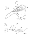
- FIGS 1, 2 and 3 show a first embodiment of a ram air channel assembly 10.
- the ram air channel assembly 10 comprises a first ram air inlet 12, a second ram air inlet 14 that is arranged at a distance from the first ram air inlet 12, and a flap 16.
- the second ram air inlet 14 is arranged at a predetermined distance from the first ram air inlet 12 in a direction along a longitudinal axis of the aircraft towards a nose of the aircraft.
- the second ram air inlet 14 is arranged upstream of the first ram air inlet 12.
- the width of the second ram air inlet 14 exceeds the width of the first ram air inlet 12 by about 5%.
- the first ram air inlet 12 comprises a protruding portion 18 which is designed in the form of a scoop air inlet and protrudes from an outer surface 20 of a section 22 of the aircraft outer skin.
- the first ram air inlet 12 is coupled to a first ram air inlet channel 24, which, at an inlet region thereof, has a linearly inclined wall portion 26.
- the first ram air channel 24 serves to supply ram air to a first ambient air consuming system (not shown) of the aircraft.
- the protruding portion 18 comprises a deflector 36 adapted to guide an air flow that passes the section 22 of the aircraft outer skin into the first ram air inlet channel 24.
- the second ram air inlet 14 has a cross-sectional area that is arranged flush with the section 22 of the outer skin of the aircraft and is coupled to a second ram air inlet channel 28, which, at an inlet region thereof, has a linearly inclined wall portion 30.
- the second ram air channel 28 serves to supply ram air to a second ambient air consuming system (not shown) of the aircraft.
- the first and the second ram air inlet channel 24, 28 are formed separate from each other, thus allowing the first and the second ambient air consuming system to be independently supplied with ram air.
- the flap 16 is pivotable about a flap axis 32 relative to the section 22 of the aircraft outer skin between a first and a second operating position, wherein the flap axis 32 is arranged upstream of the second ram air inlet 14 and extends in a direction substantially perpendicular to the direction of flow 34 of the air flow passing the section 22 of the aircraft outer skin during flight operation of the aircraft.
- the direction of flow 34 is substantially opposed to the flight direction of the aircraft.
- the flap 16 is shown in its first operating position, in which it projects into the second ram air channel 28 in order to control the air flow through the second ram air inlet 14 into the second ram air channel 28.
- the flap 16 When the flap 16 is disposed in its first operating position, the air flow passing the section 22 of the aircraft outer skin follows an outer surface of the flap 16 into the second ram air channel 28.
- the flap 16 In its first operating position, the flap 16 defines a maximum inclination angle of approximately 10° with the section 22 of the aircraft outer skin.
- the maximum inclination angle defined between the flap 16 and the section 22 of the aircraft outer skin in the first operating position of the flap 16 is smaller than an inclination angle between the linearly inclined wall portion 30 of the second ram air inlet channel 28 and the section 22 of the aircraft outer skin, which is set to approximately 15°, in order to ensure proper operation of the flap 16.
- the flap 16 When the flap 16 is arranged in its second operating position and projects into the air flow passing the section 22 of the aircraft outer skin as shown in Figure 3 , the flap 16 prevents foreign objects from entering the first and the second ram air inlet 12, 14. In its second operating position, the flap 16 defines an inclination angle of approximately -30° with the section 22 of the aircraft outer skin. As shown in Figure 3 , the flap 16 projects deeply enough into the air flow passing the section 22 of the aircraft outer skin that both, the first and the second ram air inlet 12, 14 are entirely shielded.
- the ram air channel assembly 10 further comprises a control unit 38 for controlling the operation of the flap 16.
- the control unit 38 may control a drive unit such as, for example an electric drive motor (not shown) which serves to drive the flap 16 into the desired operating position.
- the control unit 38 controls the flap 16 into its first operating position when the aircraft is flying at cruising altitude.
- the flap 16 is used to control the ram air flow into the second ram air inlet channel 28.
- the flap 16 under the control of the control unit 38, may be moved from the first operating position shown in Figures 1 and 2 , wherein the flap 16 defines a maximum inclination angle of approximately 10° with the section 22 of the aircraft outer skin into a modified first operating position, wherein the flap 16 defines an inclination angle of less than 10° with the section 22 of the aircraft outer skin, in order to lower the air flow into the second ram air channel 28.
- a further modified first operating position wherein the flap 16 extends flush with the section 22 of the aircraft outer skin and hence closes the second ram air inlet 14.
- control unit 38 controls the flap 16 into its second operating position.
- the flap 16 protects the first and the second ram air inlet 12, 14 from foreign object damage.
- Figures 4 and 5 show a second embodiment of a ram air channel assembly 50 which differs from the first embodiment according to Figures 1 to 3 in that the ram air channel assembly 50 comprises an additional ram air outlet 52 that is arranged downstream of the first ram air inlet 12.
- the ram air outlet 52 is arranged at a predetermined distance from the first ram air inlet 12 in a direction along a longitudinal axis of the aircraft and in a direction of a tail of the aircraft.
- a cross-sectional area of the ram air outlet 52 is arranged flush with the section of the aircraft outer skin 22.
- the ram air outlet 52 is coupled to a ram air outlet channel 53, which serves to discharge ram air supplied to the aircraft via at least one ram air inlet channel, in particular the first and/or the second ram air inlet channel 24, 28, from the aircraft back into the environment.
- the ram air outlet channel 53 in an outlet region thereof, is provided with a linearly inclined wall portion 54 which defines an inclination angle of approximately 30° with the section 22 of the aircraft outer skin.
- the structure and the function of the ram air channel assembly 50 according to Figures 4 and 5 correspond to the structure and the function of the ram air channel assembly 10 according to Figures 1 to 3 .
- a ram air channel assembly 70 comprises an elongated stabilization rod 72, which is pivotably coupled to the flap 16 and to a rail system 74.
- the pivotable coupling to the flap 16 is implemented by a first bearing 76
- the pivotable coupling to the rail system 74 is implemented by a second bearing 78.
- the stabilization rod 72 and the rail system 74 are adapted to interact with each other in order to set an inclination angle of the flap 16.
- the rail system 74 is arranged in the second ram air channel 28 and fastened to the inclined wall portion 30 of the second ram air inlet channel 28.
- the structure and the function of the ram air channel assembly 70 according to Figure 6 correspond to the structure and the function of the ram air channel assembly 10 according to Figures 1 to 3 .
- Figures 7 to 10 show a fourth embodiment of a ram air channel assembly 90, wherein the section 22 of the aircraft outer skin accommodating the first ram air inlet 12 and the second ram air inlet 14 is be curved in the direction substantially perpendicular to the direction of flow 34 of the air flow passing the section 22 of the aircraft outer skin, i.e. in a direction perpendicular to a longitudinal axis of an aircraft equipped with the ram air channel assembly 90. Further, the section 22 of the aircraft outer skin accommodating the first ram air inlet 12 and the second ram air inlet 14 comprises a lowered portion 40 which is lowered relative to the aircraft outer skin surrounding the ram air channel assembly 90.
- the lowered portion 40 of the section 22 of the aircraft outer skin is disposed between the first and the second ram air inlet 12, 14 so as to separate the first and the second ram air inlet 12, 14 from each other.
- the protruding portion 18 of first ram air inlet 12 protrudes from the lowered portion 40 of the section 22 of the aircraft outer skin.
- An outer surface of the protruding portion 18 of first ram air inlet 12, however, is arranged flush with the aircraft outer skin surrounding the ram air channel assembly 90.
- the cross-sectional area of the second ram air inlet 14 is lowered and inclined relative to the aircraft outer skin surrounding the ram air channel assembly 90. Specifically, the cross-sectional area of the second ram air inlet 14 is inclined starting from a level of the aircraft outer skin adjacent to the ram air channel assembly 90 upstream of the ram air channel assembly 90 in the direction of the first ram air inlet 14 until reaching the lowered portion 40 of the section 22 of the aircraft outer skin separating the first and the second ram air inlet 12, 14.
- the flap 16 of the ram air channel assembly 90 shown in Figures 7 to 10 in its first operating position, defines a maximum inclination angle of approximately 10° with the aircraft outer skin surrounding the ram air channel assembly 90, in order to allow a maximum volume flow of ram air entering the second ram air channel 28.
- the flap 16 In order to close the second ram air inlet 14, the flap 16, however, no longer is arranged flush with the section 22 of the aircraft outer skin accommodating the ram air channel assembly 90 and the aircraft outer skin surrounding the ram air channel assembly 90, but still defines a positive inclination angle of, for example, approximately 5° with the aircraft outer skin surrounding the ram air channel assembly 90 (see position of the flap 16 indicated as a dashed line in Figure 8 ).
- the flap 16 When the flap 16 is arranged in its second operating position and projects into the air flow passing the section 22 of the aircraft outer skin as shown in Figures 9 and 10 , in order to prevent foreign objects from entering the first and the second ram air inlet 12, 14, the flap 16 extends substantially flush with the aircraft outer skin surrounding the ram air channel assembly 90 or defines a small inclination angle of approximately -5° with the aircraft outer skin surrounding the ram air channel assembly 90. Hence, the flap 16, in its second operating position shields the first and the second ram air inlet 12, 14, but does not significantly add to the aerodynamic drag of the aircraft.
- the structure and the function of the ram air channel assembly 90 according to Figures 7 to 10 correspond to the structure and the function of the ram air channel assembly 10 according to Figures 1 to 3 .
- FIG 11 shows a fifth embodiment of a ram air channel assembly 110.
- the flap 16 is movable between a first operating position (shown in solid lines in Figure 11 ) and a second operating position (shown in dashed lines in Figure 11 ).
- the flap 16 comprises a first section 118 arranged adjacent to the axis 32, and a second section 120 arranged downstream of the first section.
- An end 124 of the second section 120 which faces the first section 118 is pivotably coupled to an end 126 of the first section 118 which faces the second section 120 by a hinge 122.
- the second section 120 projects into the second ram air inlet channel 28 independent of the operating position of the flap 16.
- An actuating device 128 serves to interact with the second section 120 of the flap 16, in order to set an inclination angle of the first section 118 of the flap 16 relative to the section 22 of the aircraft outer skin.
- the actuating device 128 is pivotably coupled to the second section 120 of the flap 16, and comprises a hydraulic drive 130.
- the hydraulic drive 130 causes a linear or rotational displacement of a deflection mechanism 132, which in turn causes a displacement of the second section 120 of the flap 16.
- the deflection mechanism 132 converts the direction and magnitude of a force vector and a displacement vector provided by the hydraulic drive 130 by five pivot axes 134, 136, 138, 140, 142 and is pivotably coupled to the second section 120 of the flap 16.
- the structure and the function of the ram air channel assembly 110 according to Figure 11 correspond to the structure and the function of the ram air channel assembly 10 according to Figures 1 to 3 .
- ram air channel assembly 90 may be equipped with an elongated stabilization rod 72 and a rail system 74 as depicted in Figure 6 .
Landscapes
- Health & Medical Sciences (AREA)
- General Health & Medical Sciences (AREA)
- Pulmonology (AREA)
- Engineering & Computer Science (AREA)
- Aviation & Aerospace Engineering (AREA)
- Air-Flow Control Members (AREA)
- Cooling, Air Intake And Gas Exhaust, And Fuel Tank Arrangements In Propulsion Units (AREA)
- Body Structure For Vehicles (AREA)
Abstract
Description
- The present invention relates to a ram air channel assembly for use in an aircraft and to a method for operating the ram air channel assembly.
- Commercial aircraft typically employ a number of ambient air consuming systems in order to provide a high level of comfort and safety for the crew and the passengers on board the aircraft. One prominent example of such an ambient air consuming system is the air conditioning system of the aircraft. It allows for cooling the air in the aircraft cabin, which could else be heated by sun irradiance, body heat of the passengers, and on-board devices to an uncomfortable level. Moreover, the air conditioning system supplies the passenger cabin with fresh air in order to ensure a sufficiently high oxygen concentration therein. An exemplary air conditioning system is described in
documents DE 10 2011 014 565 A1 andUS 2012/240599 A1 . Further examples for ambient air consuming systems are ventilation systems, such as systems for unpressurized bay ventilation. - The feeding of ambient air consuming systems with ambient air typically occurs via ram air inlet channels. In general, an air flow that passes a section of the aircraft outer skin enters the ram air inlet channel via a ram air inlet and thereafter is guided to the respective ambient air consuming system. The air flow guided to the ambient air consuming system is limited by the number of ram air inlets provided in the aircraft outer skin and the cross sectional area of the respective ram air inlet channels. The heated air flow exits the aircraft through ram air outlets or is supplied to the cabin.
-
Documents DE 10 2008 026 117 A1 andUS 2011/0136425 A1 describe a ram air inlet assembly featuring a first ram air inlet and a secondary air inlet that is spaced apart from the first ram air inlet. The assembly further comprises a movably mounted flap, which can be moved into a first position and into a second position. In the first position, the flap essentially covers the secondary air inlet. In the second position, the flap at least partially opens the secondary air inlet and at least in certain areas extends into the air flow directed toward the first ram air inlet in order to shield the first ram air inlet from foreign matter. - The present invention is directed to the object to provide a light-weight and aerodynamically optimized ram air channel assembly which can be operated in a particularly reliable manner. Further, the invention is directed to the object to provide a method of operating a ram air channel assembly of this kind.
- This problem is solved by a ram air channel assembly having the features of claim 1 and by a method of operating a ram air channel assembly according to claim 13.
- A ram air channel assembly for an aircraft comprises a first ram air inlet having a protruding portion which protrudes from an outer surface of a section of an aircraft outer skin. The first ram air inlet is coupled to a first ram air inlet channel. The protruding portion may comprise a deflector adapted to guide an air flow that passes the section of the aircraft outer skin during flight operation of an aircraft equipped with the ram air channel assembly into the first ram air inlet channel. The ram air inlet channel assembly further comprises a second ram air inlet having a cross-sectional area arranged flush with the section of the outer skin of the aircraft. The second ram air inlet is coupled to a second ram air inlet channel, and is arranged proximate to the first ram air inlet at a predetermined distance from the first ram air inlet upstream of the first ram air inlet.
- When the ram air channel assembly is mounted in an aircraft, the second ram air inlet preferably is arranged at a predetermined distance from the first ram air inlet in a direction along a longitudinal axis of the aircraft. Within the context of this application, the terms "upstream" and "downstream" are used with reference to a direction of flow of the air flow that passes the section of the aircraft outer skin during flight operation of an aircraft equipped with the ram air channel assembly. Typically, the air flow follows the contour of the aircraft outer skin in a general direction which, during flight operation of an aircraft, is opposed to the flight direction of the aircraft. Hence, when the ram air channel assembly is mounted in an aircraft, the second ram air inlet is arranged at a predetermined distance from the first ram air inlet in a direction of a nose of the aircraft
- The ram air channel assembly further comprises a flap, which, at least in sections, is pivotable about an axis relative to the section of the aircraft outer skin between a first and a second operating position. The axis is arranged upstream of the first and the second ram air inlet and extends in a direction substantially perpendicular to the direction of flow of the air flow passing the section of the aircraft outer skin. In the ram air channel assembly, the entire flap may be pivotable about the axis relative to the section of the aircraft outer skin. It is, however, also conceivable that the flap comprises plural sections, wherein only one section, typically the section disposed adjacent to the axis, is pivotable about the axis relative to the section of the aircraft outer skin. In its first operating position, the flap projects into the second ram air inlet channel, in order to control the air flow through the second ram air inlet into the second ram air inlet channel. In its second operating position, the flap projects into the air flow passing the section of the aircraft outer skin, in order to prevent foreign objects from entering the first and the second ram air inlet opening.
- When the flap is arranged in its first or second operating position and projects into the second ram air inlet or into the air flow passing the section of the aircraft outer skin, respectively, the flap may be inclined with respect to the section of the aircraft outer skin and may define an inclination angle with the section of the aircraft outer skin. Specifically, in its first operating position, the flap may define a positive inclination angle with the section of the aircraft outer skin, whereas the flap being disposed in its second operation position may define a negative inclination angle with the section of the aircraft outer skin.
- In its first operating position, the flap may define various inclination angles with the section of the aircraft outer skin, in order to control the air flow through the second ram air inlet into the second ram air inlet channel. Preferably, however, the maximum inclination angle which is defined between the flap being disposed in its first operation position and the section of the aircraft outer skin does not exceed approximately 10°. When the flap, in its first operating position, defines its maximum inclination angle with the aircraft outer skin, the flap allows a maximum air flow into the second ram air channel. When the flap, in its first operating position, defines an inclination angle of less than the maximum inclination angle with the aircraft outer skin, the flap lowers the air flow into the second ram air channel. Finally, the flap, in its first operating position, may extend flush with the section of the aircraft outer skin and hence close the second ram air inlet, while still allowing ram air to enter the first ram air inlet. The inclination angle which is defined between the flap being disposed in its second operation position and the section of the aircraft outer skin advantageously may be larger than approximately -45°.
- In the ram air channel assembly, the flap fulfills the double function to control the air flow through the second ram air inlet into the second ram air inlet channel in its first operating position, and to protect the first and the second ram air inlet from foreign object damage in its second operating position. Hence, the ram air inlet channel assembly can be operated in a safe and reliable manner and, at the same time, can be of a particularly lightweight design. Further, since the flap, in its first operating position, projects into the second ram air inlet channel, the flap allows ram air to enter the first ram air channel, but adds to the aerodynamic drag and thus the additional fuel consumption of the aircraft only to a limited extent.
- Preferably, the width of the second ram air inlet in the direction perpendicular to the direction of flow of the air flow passing the section of the aircraft outer skin is equal to or exceeds the width of the first ram air inlet. However, the width of the first ram air inlet in the direction perpendicular to the direction of flow of the air flow passing the section of the aircraft outer skin may alternatively exceed the width of the second ram air inlet. For example, the width of the second ram air inlet in the direction perpendicular to the direction of flow of the air flow passing the section of the aircraft outer skin and perpendicular to the longitudinal axis of the aircraft may exceed the width of the first ram air inlet opening by more than approximately 10 %. Advantageously, the length of the first ram air inlet in the direction of flow of the air flow passing the section of the aircraft outer skin and along the longitudinal axis of the aircraft may exceed the length of the second ram air inlet. This design allows both, the first and the second ram air inlet channel, to be supplied with a sufficient amount of ram air, while still maintaining a compact design and a low weight of the ram air channel assembly.
- In a preferred embodiment of the invention, the first ram air inlet channel is coupled to a first ambient air consuming system of the aircraft and the second ram air inlet channel is coupled to a second ambient air consuming system of the aircraft. Alternatively, both ram air inlet channels may be coupled to the same ambient air consuming system.
- Preferably, the first and the second ram air inlet channel are formed separate from each other. In particular, the first and the second ram air inlet channel may be designed so as to be independent from each other without a connection being provided between the first and the second ram air inlet channel. Hence, ambient air consuming systems connected to the first and the second ram air inlet channel, respectively, can be supplied with ambient air independent from each other.
- The first and the second ambient air consuming system may be selected from the group of a fresh air generation system of an aircraft air conditioning system, an emergency ventilation system, a system for unpressurized bay ventilation, a heat exchanger, and an auxiliary power unit. Preferably, the second ram air channel is associated with a heat exchanger for cooling purposes, while the first ram air channel may be utilized as a fresh air supply for the aircraft cabin. Alternatively, one of the first and the second ram air inlet channel is associated with a fresh air generation system of an air conditioning system of the aircraft and the other ram air inlet channel is associated with a system for unpressurized bay ventilation. In another alternative, the first ram air channel is associated with a system for unpressurized bay ventilation, and the second ram air channel is associated with a fresh air generation system of an aircraft air conditioning system. In such a configuration, the unpressurized bay can be constantly ventilated, as it is generally desired for ideal pressure conditions within the aircraft, while the volume flow of ram air supplied to the fresh air generation system of the aircraft air conditioning system can be flexibly adapted in dependence on the operational state of the aircraft air conditioning system.
- The first ram air inlet channel, in an inlet region thereof, may be provided with a linearly inclined wall portion. Alternatively or additionally thereto, the second ram air inlet channel, in an inlet region thereof, may be provided with a linearly inclined wall portion. The linearly inclined wall portion of the first and/or the second ram air inlet channel may define an inclination angle with the section of the aircraft outer skin which may be selected in dependence on the maximum inclination angle, the flap defines with the section of the aircraft outer skin, in particular in its first operating position. Specifically, the inclination angle between the linearly inclined wall portion of the second ram air inlet channel and the section of the aircraft outer skin may be larger than the maximum inclination angle defined between the flap in its first operating position and the section of the aircraft outer skin. For example, the inclination angle between the linearly inclined wall portion of the second ram air inlet channel and the section of the aircraft outer skin may be approximately 15°, wherein the maximum inclination angle defined between the flap in its first operating position and the section of the aircraft outer skin may be approximately 10°. Further, the inclination angle between the linearly inclined wall portion of the first ram air inlet channel and the section of the aircraft outer skin may be smaller than the inclination angle defined between the linearly inclined wall portion of the second ram air inlet channel and the section of the aircraft outer skin.
- The protruding portion of the first ram air inlet may have the shape of a scoop air inlet, allowing an efficient supply of ram air into the first ram air inlet channel. The first ram air inlet may be designed in the form of a NACA (National Advisory Committee for Aeronautics) inlet.
- The ram air channel assembly may further comprise a ram air outlet having a cross-sectional area arranged flush with the section of the aircraft outer skin. The ram air outlet may be coupled to a ram air outlet channel which may serve to discharge ram air supplied to the aircraft via at least one ram air inlet channel, for example the first and/or the second ram air inlet channel, from the aircraft back into the environment. Preferably, the ram air outlet is arranged proximate to the first ram air inlet at a predetermined distance from the first ram air inlet opening downstream of the first ram air inlet opening. When the ram air channel assembly is mounted in an aircraft, the ram air outlet preferably is arranged at a predetermined distance from the first ram air inlet channel in a direction along a longitudinal axis of the aircraft and in a direction of a tail of the aircraft.
- A ram air channel assembly which may be claimed in independent form comprises a first ram air inlet having a protruding portion which protrudes from an outer surface of a section of an aircraft outer skin. The first ram air inlet may be coupled to a first ram air inlet channel. The protruding portion may comprise a deflector adapted to guide an air flow that passes the section of the aircraft outer skin during flight operation of an aircraft equipped with the ram air channel assembly into the first ram air inlet channel. This ram air inlet channel assembly further comprises a ram air outlet having a cross-sectional area arranged flush with the section of the aircraft outer skin. The ram air outlet may be coupled to a ram air outlet channel which may serve to discharge ram air supplied to the aircraft via at least one ram air inlet channel, for example the first ram air inlet channel, from the aircraft back into the environment. The ram air outlet is arranged proximate to the first ram air inlet at a predetermined distance from the first ram air inlet opening downstream of the first ram air inlet opening. When the ram air channel assembly is mounted in an aircraft, the ram air outlet preferably is arranged at a predetermined distance from the first ram air inlet channel in a direction along a longitudinal axis of the aircraft and in a direction of a tail of the aircraft.
- A ram air inlet channel assembly comprising a first ram air inlet having a protruding portion which protrudes from an outer surface of a section of an aircraft outer skin and a ram air outlet may further comprise some or all of the features of the ram air inlet channel assembly provided with a first and a second ram air inlet. These features, however, are not essential for this ram air inlet channel assembly.
- The ram air outlet channel, in an outlet region thereof, may be provided with a linearly inclined wall portion. The inclined wall portion of the ram air outlet channel may define an inclination angle with the section of the aircraft outer skin which is larger than the inclination angle defined between the inclined wall portion of the first or the second ram air inlet channel and the section of the aircraft outer skin. For example, the inclination angle defined between the inclined wall portion of the ram air outlet channel and the section of the aircraft outer skin may be in the range of approximately 25° to approximately 45°. Preferably, the inclination angle defined between the inclined wall portion of the ram air outlet channel and the section of the aircraft outer skin is approximately 30°.
- The ram air channel assembly may further comprise at least one elongated stabilization rod. Advantageously, the stabilization rod may be pivotably coupled to the flap and/or to a rail system. Preferably, the stabilization rod and the rail system are adapted to interact with each other in order to set an inclination angle of the flap relative to the section of the aircraft outer skin. The rail system may be arranged in the second ram air inlet channel and, in particular, may be fastened to the inclined wall portion of the second ram air inlet channel.
- The section of the aircraft outer skin accommodating the first ram air inlet and the second ram air inlet may be curved in the direction substantially perpendicular to the direction of flow of the air flow passing the section of the aircraft outer skin. Such an arrangement allows for utilizing the available space within the aircraft in a particularly efficient manner.
- The section of the aircraft outer skin accommodating the first ram air inlet and the second ram air inlet may comprise a lowered portion which is lowered relative to the aircraft outer skin surrounding the ram air channel assembly. The lowered portion of the section of the aircraft outer skin may be disposed between the first and the second ram air inlet so as to separate the first and the second ram air inlet from each other. In this configuration of the ram air channel assembly, the protruding portion of first ram air inlet may protrude from the lowered portion of the section of the aircraft outer skin. An outer surface of the protruding portion of first ram air inlet, however, may be arranged flush with the aircraft outer skin surrounding the ram air channel assembly. Consequently, the protruding portion of the first ram air inlet does not protrude relative to the aircraft outer skin surrounding the ram air channel allowing the additional aerodynamic drag caused by the ram air channel assembly to be further reduced.
- In particular in a ram air channel assembly which comprises a first ram air inlet, the protruding portion of which protrudes from a lowered portion of the section of the aircraft outer skin, the cross-sectional area of the second ram air inlet may be lowered and inclined relative to the aircraft outer skin surrounding the ram air channel assembly. Specifically, the cross-sectional area of the second ram air inlet may be inclined starting from a level of the aircraft outer skin adjacent to the ram air channel assembly upstream of the ram air channel assembly in the direction of the first ram air inlet until reaching the lowered portion of the section of the aircraft outer skin separating the first and the second ram air inlet.
- The flap may comprise a first section that is preferably arranged adjacent to the axis about which the flap is pivotable. Advantageously, the flap may further comprise a second section that may be arranged downstream of the first section. In order to reduce turbulences arising at an end of the first section of the flap which faces the second section of the flap when the air flow passes the section of the aircraft outer skin, which is particularly the case when the flap is disposed in its second operating position, the second section may be joined to the first section. In particular, the second section may be pivotably coupled to the first section, for example by a hinge. In such a configuration, an end of the second section which faces the first section is preferably pivotably coupled to the end of the first section which faces the second section by the hinge.
- Preferably, the second section projects into the second ram air inlet channel independent of the operating position of the flap. Therefore, with respect to the section of the aircraft outer skin, the first and the second section of the flap may be inclined in opposite directions. For example, when the flap is in its first operating position with its first section projecting into the air flow passing the section of the aircraft outer skin, the second section may still project into the second ram air inlet channel.
- The ram air channel assembly may further comprise an actuating device which is adapted to interact with the first and/or the second section of the flap in order to set an inclination angle of the first and/or the second section of the flap relative to the section of the aircraft outer skin. Preferably, the actuating device is adapted to pivot the second section of the flap about an axis which is arranged in the region of an end of the second section which faces away from the first section in order to set an inclination angle of the front section of the flap relative to the section of the aircraft outer skin. The actuating device may be coupled to the hinge and may comprise the elongated stabilization rod and/or the rail system.
- In a preferred embodiment of the invention, the actuating device may comprise a drive, which may be an electro-mechanic, a hydraulic, or a pneumatic drive. Advantageously, the drive may cause a linear or rotational displacement of a deflection mechanism, which in turn may cause a movement of the second section of the flap. The deflection mechanism may be adapted to convert the direction and magnitude of a force vector or a displacement vector provided by the drive. Furthermore, the deflection mechanism may comprise at least one pivot axis and may be pivotably coupled to the second section of the flap. When the first section is coupled to the second section by the hinge, the displacement of the second section may result in a displacement of the first section.
- The ram air channel assembly may further comprise a control unit for controlling an operation of the flap. Specifically, the control unit may be adapted to control the flap into its first operating position when the aircraft is flying at cruising altitude, and to control the flap into its second operating position during take-off and/or landing of the aircraft. During take-off and/or landing of the aircraft, the first and the second ram air inlet thus can be protected from foreign object damage in a particularly effective manner. Contrary thereto, the flap is used to control the ram air flow into the second ram air inlet channel when the aircraft is flying at cruising altitude, wherein the flap projects in an aerodynamically favorable manner into the second ram channel.
- In a method for operating a ram air channel assembly as described above, the flap is controlled into its first operating position when the aircraft is flying at cruising altitude. Furthermore, the flap is controlled into its second operating position during take-off and/or landing of the aircraft.
- Preferred embodiments of a ram air channel assembly in the following are described in greater detail with reference to the attached schematic drawings, wherein
- Figure 1
- shows a perspective view of a first embodiment of a ram air channel assembly, wherein a flap of the ram air channel assembly is arranged in a first operating position,
- Figure 2
- shows a cross-sectional view of the ram air channel assembly according to
Figure 1 , - Figure 3
- shows a cross-sectional view of the ram air channel assembly according to
Figure 2 , wherein the flap of the ram air channel assembly is arranged in a second operating position, - Figure 4
- shows a perspective view of a second embodiment of a ram air channel assembly, wherein a flap of the ram air channel assembly is arranged in a first operating position,
- Figure 5
- shows a cross-sectional view of the ram air channel assembly according to
Figure 4 , - Figure 6
- shows a cross-sectional view of a third embodiment of a ram air channel assembly, wherein a flap of the ram air channel assembly is arranged in a second operating position,
- Figure 7
- shows a perspective view of a fourth embodiment of a ram air channel assembly, wherein a flap of the ram air channel assembly is arranged in a first operating position,
- Figure 8
- shows a cross-sectional view of the ram air channel assembly according to
Figure 7 , - Figure 9
- shows a perspective view of the ram air channel assembly according to
Figure 7 , wherein the flap of the ram air channel assembly is arranged in a second operating position, - Figure 10
- shows a cross-sectional view of the ram air channel assembly according to
Figure 9 , and - Figure 11
- shows a cross-sectional view of a fifth embodiment of a ram air channel assembly.
-
Figures 1, 2 and3 show a first embodiment of a ramair channel assembly 10. The ramair channel assembly 10 comprises a firstram air inlet 12, a secondram air inlet 14 that is arranged at a distance from the firstram air inlet 12, and aflap 16. When the ramair channel assembly 10 is mounted in an aircraft, the secondram air inlet 14 is arranged at a predetermined distance from the firstram air inlet 12 in a direction along a longitudinal axis of the aircraft towards a nose of the aircraft. Hence, with reference to a direction offlow 34 of an air flow that passes an outer skin of the aircraft during flight operation of the aircraft, the secondram air inlet 14 is arranged upstream of the firstram air inlet 12. In a direction perpendicular to the direction offlow 34 of the air flow that passes the outer skin of the aircraft during flight operation of an aircraft, the width of the secondram air inlet 14 exceeds the width of the firstram air inlet 12 by about 5%. - The first
ram air inlet 12 comprises a protrudingportion 18 which is designed in the form of a scoop air inlet and protrudes from anouter surface 20 of asection 22 of the aircraft outer skin. The firstram air inlet 12 is coupled to a first ramair inlet channel 24, which, at an inlet region thereof, has a linearlyinclined wall portion 26. The firstram air channel 24 serves to supply ram air to a first ambient air consuming system (not shown) of the aircraft. The protrudingportion 18 comprises adeflector 36 adapted to guide an air flow that passes thesection 22 of the aircraft outer skin into the first ramair inlet channel 24. - The second
ram air inlet 14 has a cross-sectional area that is arranged flush with thesection 22 of the outer skin of the aircraft and is coupled to a second ramair inlet channel 28, which, at an inlet region thereof, has a linearlyinclined wall portion 30. The secondram air channel 28 serves to supply ram air to a second ambient air consuming system (not shown) of the aircraft. The first and the second ramair inlet channel - The
flap 16 is pivotable about aflap axis 32 relative to thesection 22 of the aircraft outer skin between a first and a second operating position, wherein theflap axis 32 is arranged upstream of the secondram air inlet 14 and extends in a direction substantially perpendicular to the direction offlow 34 of the air flow passing thesection 22 of the aircraft outer skin during flight operation of the aircraft. The direction offlow 34 is substantially opposed to the flight direction of the aircraft. - In
Figures 1 and 2 , theflap 16 is shown in its first operating position, in which it projects into the secondram air channel 28 in order to control the air flow through the secondram air inlet 14 into the secondram air channel 28. When theflap 16 is disposed in its first operating position, the air flow passing thesection 22 of the aircraft outer skin follows an outer surface of theflap 16 into the secondram air channel 28. In its first operating position, theflap 16 defines a maximum inclination angle of approximately 10° with thesection 22 of the aircraft outer skin. The maximum inclination angle defined between theflap 16 and thesection 22 of the aircraft outer skin in the first operating position of theflap 16 is smaller than an inclination angle between the linearlyinclined wall portion 30 of the second ramair inlet channel 28 and thesection 22 of the aircraft outer skin, which is set to approximately 15°, in order to ensure proper operation of theflap 16. - When the
flap 16 is arranged in its second operating position and projects into the air flow passing thesection 22 of the aircraft outer skin as shown inFigure 3 , theflap 16 prevents foreign objects from entering the first and the secondram air inlet flap 16 defines an inclination angle of approximately -30° with thesection 22 of the aircraft outer skin. As shown inFigure 3 , theflap 16 projects deeply enough into the air flow passing thesection 22 of the aircraft outer skin that both, the first and the secondram air inlet - The ram
air channel assembly 10 further comprises acontrol unit 38 for controlling the operation of theflap 16. For example, thecontrol unit 38 may control a drive unit such as, for example an electric drive motor (not shown) which serves to drive theflap 16 into the desired operating position. Specifically, thecontrol unit 38 controls theflap 16 into its first operating position when the aircraft is flying at cruising altitude. Hence, when the aircraft is flying at cruising altitude, theflap 16 is used to control the ram air flow into the second ramair inlet channel 28. Of course, theflap 16, under the control of thecontrol unit 38, may be moved from the first operating position shown inFigures 1 and 2 , wherein theflap 16 defines a maximum inclination angle of approximately 10° with thesection 22 of the aircraft outer skin into a modified first operating position, wherein theflap 16 defines an inclination angle of less than 10° with thesection 22 of the aircraft outer skin, in order to lower the air flow into the secondram air channel 28. Further, it conceivable to control theflap 16 into a further modified first operating position, wherein theflap 16 extends flush with thesection 22 of the aircraft outer skin and hence closes the secondram air inlet 14. - During take-off and landing of the aircraft, the
control unit 38 controls theflap 16 into its second operating position. Hence, during take-off and landing of the aircraft, theflap 16 protects the first and the secondram air inlet -
Figures 4 and5 show a second embodiment of a ramair channel assembly 50 which differs from the first embodiment according toFigures 1 to 3 in that the ramair channel assembly 50 comprises an additionalram air outlet 52 that is arranged downstream of the firstram air inlet 12. When the ramair channel assembly 50 is mounted in an aircraft, theram air outlet 52 is arranged at a predetermined distance from the firstram air inlet 12 in a direction along a longitudinal axis of the aircraft and in a direction of a tail of the aircraft. A cross-sectional area of theram air outlet 52 is arranged flush with the section of the aircraftouter skin 22. Theram air outlet 52 is coupled to a ramair outlet channel 53, which serves to discharge ram air supplied to the aircraft via at least one ram air inlet channel, in particular the first and/or the second ramair inlet channel air outlet channel 53, in an outlet region thereof, is provided with a linearlyinclined wall portion 54 which defines an inclination angle of approximately 30° with thesection 22 of the aircraft outer skin. - Otherwise, the structure and the function of the ram
air channel assembly 50 according toFigures 4 and5 correspond to the structure and the function of the ramair channel assembly 10 according toFigures 1 to 3 . - In a third embodiment which is shown in
Figure 6 , a ram air channel assembly 70 comprises anelongated stabilization rod 72, which is pivotably coupled to theflap 16 and to arail system 74. The pivotable coupling to theflap 16 is implemented by afirst bearing 76, and the pivotable coupling to therail system 74 is implemented by asecond bearing 78. Thestabilization rod 72 and therail system 74 are adapted to interact with each other in order to set an inclination angle of theflap 16. In the ram air channel assembly 70 ofFigure 6 , therail system 74 is arranged in the secondram air channel 28 and fastened to theinclined wall portion 30 of the second ramair inlet channel 28. - Otherwise, the structure and the function of the ram air channel assembly 70 according to
Figure 6 correspond to the structure and the function of the ramair channel assembly 10 according toFigures 1 to 3 . -
Figures 7 to 10 show a fourth embodiment of a ramair channel assembly 90, wherein thesection 22 of the aircraft outer skin accommodating the firstram air inlet 12 and the secondram air inlet 14 is be curved in the direction substantially perpendicular to the direction offlow 34 of the air flow passing thesection 22 of the aircraft outer skin, i.e. in a direction perpendicular to a longitudinal axis of an aircraft equipped with the ramair channel assembly 90. Further, thesection 22 of the aircraft outer skin accommodating the firstram air inlet 12 and the secondram air inlet 14 comprises a loweredportion 40 which is lowered relative to the aircraft outer skin surrounding the ramair channel assembly 90. The loweredportion 40 of thesection 22 of the aircraft outer skin is disposed between the first and the secondram air inlet ram air inlet portion 18 of firstram air inlet 12 protrudes from the loweredportion 40 of thesection 22 of the aircraft outer skin. An outer surface of the protrudingportion 18 of firstram air inlet 12, however, is arranged flush with the aircraft outer skin surrounding the ramair channel assembly 90. - Further, the cross-sectional area of the second
ram air inlet 14 is lowered and inclined relative to the aircraft outer skin surrounding the ramair channel assembly 90. Specifically, the cross-sectional area of the secondram air inlet 14 is inclined starting from a level of the aircraft outer skin adjacent to the ramair channel assembly 90 upstream of the ramair channel assembly 90 in the direction of the firstram air inlet 14 until reaching the loweredportion 40 of thesection 22 of the aircraft outer skin separating the first and the secondram air inlet - Like in the ram
air channel assemblies Figures 1 to 6 , theflap 16 of the ramair channel assembly 90 shown inFigures 7 to 10 , in its first operating position, defines a maximum inclination angle of approximately 10° with the aircraft outer skin surrounding the ramair channel assembly 90, in order to allow a maximum volume flow of ram air entering the secondram air channel 28. In order to close the secondram air inlet 14, theflap 16, however, no longer is arranged flush with thesection 22 of the aircraft outer skin accommodating the ramair channel assembly 90 and the aircraft outer skin surrounding the ramair channel assembly 90, but still defines a positive inclination angle of, for example, approximately 5° with the aircraft outer skin surrounding the ram air channel assembly 90 (see position of theflap 16 indicated as a dashed line inFigure 8 ). - When the
flap 16 is arranged in its second operating position and projects into the air flow passing thesection 22 of the aircraft outer skin as shown inFigures 9 and 10 , in order to prevent foreign objects from entering the first and the secondram air inlet flap 16 extends substantially flush with the aircraft outer skin surrounding the ramair channel assembly 90 or defines a small inclination angle of approximately -5° with the aircraft outer skin surrounding the ramair channel assembly 90. Hence, theflap 16, in its second operating position shields the first and the secondram air inlet - Otherwise, the structure and the function of the ram
air channel assembly 90 according toFigures 7 to 10 correspond to the structure and the function of the ramair channel assembly 10 according toFigures 1 to 3 . -
Figure 11 shows a fifth embodiment of a ramair channel assembly 110. Again, theflap 16 is movable between a first operating position (shown in solid lines inFigure 11 ) and a second operating position (shown in dashed lines inFigure 11 ). Theflap 16 comprises a first section 118 arranged adjacent to theaxis 32, and asecond section 120 arranged downstream of the first section. Anend 124 of thesecond section 120 which faces the first section 118 is pivotably coupled to an end 126 of the first section 118 which faces thesecond section 120 by ahinge 122. Thesecond section 120 projects into the second ramair inlet channel 28 independent of the operating position of theflap 16. - An
actuating device 128 serves to interact with thesecond section 120 of theflap 16, in order to set an inclination angle of the first section 118 of theflap 16 relative to thesection 22 of the aircraft outer skin. Theactuating device 128 is pivotably coupled to thesecond section 120 of theflap 16, and comprises ahydraulic drive 130. Thehydraulic drive 130 causes a linear or rotational displacement of adeflection mechanism 132, which in turn causes a displacement of thesecond section 120 of theflap 16. Thedeflection mechanism 132 converts the direction and magnitude of a force vector and a displacement vector provided by thehydraulic drive 130 by fivepivot axes second section 120 of theflap 16. - Otherwise, the structure and the function of the ram
air channel assembly 110 according toFigure 11 correspond to the structure and the function of the ramair channel assembly 10 according toFigures 1 to 3 . - Features described above in connection with only one embodiment of a ram air channel assembly may be employed also in other embodiments. For example, the ram
air channel assembly 90 according toFigures 7 to 10 may be equipped with anelongated stabilization rod 72 and arail system 74 as depicted inFigure 6 .
Claims (15)
- A ram air channel assembly (10; 50; 70; 90; 110) for an aircraft, comprising:- a first ram air inlet (12) having a protruding portion (18) which protrudes from an outer surface (20) of a section (22) of an aircraft outer skin, wherein the first ram air inlet (12) is coupled to a first ram air inlet channel (24),- a second ram air inlet (14) having a cross-sectional area arranged flush with the section (22) of the aircraft outer skin, wherein the second ram air inlet (14) is coupled to a second ram air inlet channel (28) and arranged proximate to the first ram air inlet (12) at a predetermined distance from the first ram air inlet (12) upstream of the first ram air inlet (12), and- a flap (16) which, at least in sections, is pivotable about an axis (32) relative to the section (22) of the aircraft outer skin between a first and a second operating position, wherein the axis (32) is arranged upstream of the first and the second ram air inlet (12, 14) and extends in a direction substantially perpendicular to a direction of flow of an air flow (34) passing the section (22) of the aircraft outer skin, and wherein
the flap (16) in its first operating position projects into the second ram air inlet channel (28) in order to control the air flow through the second ram air inlet (14) into the second ram air inlet channel (28), and in its second operating position projects into the air flow (34) passing the section (22) of the aircraft outer skin in order to prevent foreign objects from entering the first and the second ram air inlet (12, 14). - The ram air channel assembly according to claim 1,
wherein the width of the second ram air inlet (14) in the direction perpendicular to the direction of flow of the air flow (34) passing the section (22) of the aircraft outer skin exceeds the width of the first ram air inlet (12) by more than 10 %. - The ram air channel assembly according to any of the preceding claims, wherein the first ram air inlet channel (24) is coupled to a first ambient air consuming system of the aircraft and the second ram air inlet channel (28) is coupled to a second ambient air consuming system of the aircraft, and wherein the first and the second ambient air consuming system in particular are selected from the group of a fresh air generation system of an aircraft air conditioning system, an emergency ventilation system, a system for unpressurized bay ventilation, a heat exchanger, and an auxiliary power unit.
- The ram air channel assembly according to any of the preceding claims, wherein the first and the second ram air inlet channel (24, 28) are formed separate from each other.
- The ram air channel assembly according to any of the preceding claims, wherein at least one of the first and the second ram air inlet channel (24, 28), in an inlet region thereof, is provided with a linearly inclined wall portion (26, 30).
- The ram air channel assembly according to any of the preceding claims, wherein the protruding portion (18) of the first ram air inlet (12) has the shape of a scoop air inlet.
- The ram air channel assembly according to any of the preceding claims, further comprising a ram air outlet (52) having a cross-sectional area arranged flush with the section (22) of the aircraft outer skin, wherein the ram air outlet (52) is coupled to a ram air outlet channel (53) and arranged proximate to the first ram air inlet (12) at a predetermined distance from the first ram air inlet (12) downstream of the first ram air inlet (12).
- The ram air channel assembly according to claim 7,
wherein the ram air outlet channel (53), in an outlet region thereof, is provided with a linearly inclined wall portion (54). - The ram air channel assembly according to any of the preceding claims, further comprising at least one elongated stabilization rod (72), which is pivotably coupled to the flap (16, 116) and to a rail system (74), wherein the stabilization rod (72) and the rail system (74) are adapted to interact with each other in order to set an inclination angle of the flap (16, 116) relative to the section (22) of the aircraft outer skin.
- The ram air channel assembly according to any of the preceding claims, wherein the section (22) of the aircraft outer skin is curved in the direction substantially perpendicular to the direction of flow (34) of the air flow passing the section (22) of the aircraft outer skin.
- The ram air channel assembly according to any of the preceding claims, wherein the section (22) of the aircraft outer skin comprises a lowered portion (40) which is disposed between the first and the second ram air inlet (12, 14) and which is lowered relative to the aircraft outer skin surrounding the ram air channel assembly (10), and wherein the protruding portion (18) of first ram air inlet (12) protrudes from the lowered portion (40) of the section (22) of the aircraft outer skin.
- The ram air channel assembly according to any of the preceding claims, wherein the cross-sectional area of the second ram air inlet (14) is lowered and inclined relative to the aircraft outer skin surrounding the ram air channel assembly (10).
- The ram air channel assembly according to any of the preceding claims, wherein the flap (16) comprises a first section (118) arranged adjacent to the axis (32), and a second section (120) arranged downstream of the first section (118), wherein the second section (120) preferably is pivotably coupled to the first section (118), and wherein the ram air channel assembly (110) in particular further comprises an actuating device (124) which is adapted to interact with the second section (120) of the flap (16) in order to set an inclination angle of the first section (118) and the second section (120) of the flap (16) relative to the section (22) of the aircraft outer skin.
- The ram air channel assembly according to any of the preceding claims, further comprising a control unit (38) for controlling an operation of the flap (16), the control unit (38) being adapted to control the flap (16) into its first operating position when the aircraft is flying at cruising altitude, and to control the flap (16) into its second operating position during take-off and/or landing of the aircraft.
- A method for operating a ram air channel assembly according to one of claims 1 to 14, the method comprising the steps:- controlling the flap (16) into its first operating position when the aircraft is flying at cruising altitude, and- controlling the flap (16) into its second operating position during take-off and/or landing of the aircraft.
Priority Applications (4)
| Application Number | Priority Date | Filing Date | Title |
|---|---|---|---|
| EP13161947.0A EP2786935B1 (en) | 2013-04-02 | 2013-04-02 | Ram air channel assembly and method for operating a ram air channel assembly |
| CN201410123950.3A CN104097777B (en) | 2013-04-02 | 2014-03-28 | Ram air channel assembly and method for operating a ram air channel assembly |
| US14/231,993 US10035601B2 (en) | 2013-04-02 | 2014-04-01 | Ram air channel assembly and method for operating a ram air channel assembly |
| US16/049,012 US10196148B1 (en) | 2013-04-02 | 2018-07-30 | Ram air channel assembly and method for operating a ram air channel assembly |
Applications Claiming Priority (1)
| Application Number | Priority Date | Filing Date | Title |
|---|---|---|---|
| EP13161947.0A EP2786935B1 (en) | 2013-04-02 | 2013-04-02 | Ram air channel assembly and method for operating a ram air channel assembly |
Publications (2)
| Publication Number | Publication Date |
|---|---|
| EP2786935A1 true EP2786935A1 (en) | 2014-10-08 |
| EP2786935B1 EP2786935B1 (en) | 2016-09-07 |
Family
ID=47998319
Family Applications (1)
| Application Number | Title | Priority Date | Filing Date |
|---|---|---|---|
| EP13161947.0A Not-in-force EP2786935B1 (en) | 2013-04-02 | 2013-04-02 | Ram air channel assembly and method for operating a ram air channel assembly |
Country Status (3)
| Country | Link |
|---|---|
| US (2) | US10035601B2 (en) |
| EP (1) | EP2786935B1 (en) |
| CN (1) | CN104097777B (en) |
Cited By (3)
| Publication number | Priority date | Publication date | Assignee | Title |
|---|---|---|---|---|
| DE102015223548A1 (en) * | 2015-11-27 | 2017-06-01 | Airbus Operations Gmbh | Aircraft air conditioning system with ambient air supply and method for operating such an aircraft air conditioning system |
| DE102016204911A1 (en) | 2016-03-24 | 2017-09-28 | Airbus Operations Gmbh | An aircraft air conditioning system having an electrically driven ambient air compressor and method of operating such an aircraft air conditioning system |
| EP3524524B1 (en) * | 2018-02-13 | 2022-09-21 | Liebherr-Aerospace Toulouse SAS | Dynamic air intake, environmental control device, engine and vehicle equipped with such an intake |
Families Citing this family (10)
| Publication number | Priority date | Publication date | Assignee | Title |
|---|---|---|---|---|
| PL3129720T3 (en) * | 2014-04-07 | 2021-01-11 | Prihoda S.R.O. | Air-conditioning diffuser for air distribution |
| CN105644789B (en) * | 2014-12-05 | 2017-10-13 | 石家庄飞机工业有限责任公司 | Aircraft preshoot is pressed into gas heat-exchange device |
| DE102015219286A1 (en) * | 2015-10-06 | 2017-04-06 | Airbus Operations Gmbh | Device for determining an opening degree of an air opening and / or a cross section of an air duct adjoining the opening |
| FR3065438A1 (en) * | 2017-04-25 | 2018-10-26 | Airbus Operations | MULTIPOSITION AIR INTAKE SYSTEM FOR AN AIRCRAFT |
| EP3466811B1 (en) * | 2017-10-09 | 2023-06-21 | Airbus Operations GmbH | Vertical tail unit for flow control |
| ES2927476T3 (en) * | 2017-10-09 | 2022-11-07 | Airbus Operations Gmbh | Vertical tail unit for flow control |
| FR3095639B1 (en) * | 2019-04-30 | 2021-04-02 | Airbus Helicopters | Rotorcraft equipped with an aerodynamic device comprising a fairing with an air inlet |
| EP4292941A1 (en) * | 2022-06-15 | 2023-12-20 | Zero Emissions Aerospace Limited | Aircraft fuel cell air supply anti contamination system |
| US12466548B2 (en) * | 2023-11-17 | 2025-11-11 | Rtx Corporation | Aircraft vertical stabilizer with air system |
| CN119508065B (en) * | 2024-10-14 | 2025-11-25 | 中国商用飞机有限责任公司 | Aircraft engine fan air intake structure and aircraft including such structure |
Citations (8)
| Publication number | Priority date | Publication date | Assignee | Title |
|---|---|---|---|---|
| US4174083A (en) * | 1977-04-29 | 1979-11-13 | The Boeing Company | Flow deflector for fluid inlet |
| US4836473A (en) * | 1985-06-14 | 1989-06-06 | Messerschmitt-Boelkow-Blohm Gmbh | Apparatus for influencing a boundary layer on the surface of a body moving through a medium |
| US20080099631A1 (en) * | 2006-10-26 | 2008-05-01 | Parikh Pradip G | Tandem air inlet apparatus and method for an airborne mobile platform |
| DE102007052817A1 (en) * | 2007-11-06 | 2009-05-07 | Liebherr-Aerospace Lindenberg Gmbh | Device for supplying air to airplane air conditioning unit, has adjustable damper to block inlet channel in position and unblock in another position, and stands in area before inlet opening of another air inlet channel in third position |
| WO2009064288A1 (en) * | 2007-11-13 | 2009-05-22 | The Boeing Company | Cabin air and heat exchanger ram air inlets for aircraft environmental control systems, and associated method of use |
| DE102008026117A1 (en) | 2008-05-30 | 2009-12-10 | Airbus Deutschland Gmbh | Fresh air intake for an aircraft |
| US20110073716A1 (en) * | 2009-09-30 | 2011-03-31 | Airbus Operations Gmbh | Ram Air Duct Flap Arrangement And Ram Air Duct |
| DE102011014565A1 (en) | 2011-03-21 | 2012-09-27 | Airbus Operations Gmbh | Air conditioning system for an aircraft |
Family Cites Families (2)
| Publication number | Priority date | Publication date | Assignee | Title |
|---|---|---|---|---|
| DE10201426B8 (en) * | 2002-01-16 | 2004-09-02 | Liebherr-Aerospace Lindenberg Gmbh | Cooling system |
| DE10301465B4 (en) * | 2003-01-16 | 2007-07-12 | Liebherr-Aerospace Lindenberg Gmbh | Cooling system |
-
2013
- 2013-04-02 EP EP13161947.0A patent/EP2786935B1/en not_active Not-in-force
-
2014
- 2014-03-28 CN CN201410123950.3A patent/CN104097777B/en active Active
- 2014-04-01 US US14/231,993 patent/US10035601B2/en active Active
-
2018
- 2018-07-30 US US16/049,012 patent/US10196148B1/en active Active
Patent Citations (10)
| Publication number | Priority date | Publication date | Assignee | Title |
|---|---|---|---|---|
| US4174083A (en) * | 1977-04-29 | 1979-11-13 | The Boeing Company | Flow deflector for fluid inlet |
| US4836473A (en) * | 1985-06-14 | 1989-06-06 | Messerschmitt-Boelkow-Blohm Gmbh | Apparatus for influencing a boundary layer on the surface of a body moving through a medium |
| US20080099631A1 (en) * | 2006-10-26 | 2008-05-01 | Parikh Pradip G | Tandem air inlet apparatus and method for an airborne mobile platform |
| DE102007052817A1 (en) * | 2007-11-06 | 2009-05-07 | Liebherr-Aerospace Lindenberg Gmbh | Device for supplying air to airplane air conditioning unit, has adjustable damper to block inlet channel in position and unblock in another position, and stands in area before inlet opening of another air inlet channel in third position |
| WO2009064288A1 (en) * | 2007-11-13 | 2009-05-22 | The Boeing Company | Cabin air and heat exchanger ram air inlets for aircraft environmental control systems, and associated method of use |
| DE102008026117A1 (en) | 2008-05-30 | 2009-12-10 | Airbus Deutschland Gmbh | Fresh air intake for an aircraft |
| US20110136425A1 (en) | 2008-05-30 | 2011-06-09 | Airbus Operations Gmbh | Fresh air inlet for an aircraft |
| US20110073716A1 (en) * | 2009-09-30 | 2011-03-31 | Airbus Operations Gmbh | Ram Air Duct Flap Arrangement And Ram Air Duct |
| DE102011014565A1 (en) | 2011-03-21 | 2012-09-27 | Airbus Operations Gmbh | Air conditioning system for an aircraft |
| US20120240599A1 (en) | 2011-03-21 | 2012-09-27 | Airbus Operations Gmbh | Air conditioning system for an aircraft |
Cited By (5)
| Publication number | Priority date | Publication date | Assignee | Title |
|---|---|---|---|---|
| DE102015223548A1 (en) * | 2015-11-27 | 2017-06-01 | Airbus Operations Gmbh | Aircraft air conditioning system with ambient air supply and method for operating such an aircraft air conditioning system |
| US10435160B2 (en) | 2015-11-27 | 2019-10-08 | Airbus Operations Gmbh | Aircraft air conditioning system with ambient air supply and method for operating such an aircraft air conditioning system |
| DE102016204911A1 (en) | 2016-03-24 | 2017-09-28 | Airbus Operations Gmbh | An aircraft air conditioning system having an electrically driven ambient air compressor and method of operating such an aircraft air conditioning system |
| US10202197B2 (en) | 2016-03-24 | 2019-02-12 | Airbus Operations Gmbh | Aircraft air conditioning system with an electrically driven ambient air compressor and method for operating such an aircraft air conditioning system |
| EP3524524B1 (en) * | 2018-02-13 | 2022-09-21 | Liebherr-Aerospace Toulouse SAS | Dynamic air intake, environmental control device, engine and vehicle equipped with such an intake |
Also Published As
| Publication number | Publication date |
|---|---|
| CN104097777A (en) | 2014-10-15 |
| US20190023404A1 (en) | 2019-01-24 |
| US20140295747A1 (en) | 2014-10-02 |
| US10196148B1 (en) | 2019-02-05 |
| CN104097777B (en) | 2017-04-12 |
| EP2786935B1 (en) | 2016-09-07 |
| US10035601B2 (en) | 2018-07-31 |
Similar Documents
| Publication | Publication Date | Title |
|---|---|---|
| US10196148B1 (en) | Ram air channel assembly and method for operating a ram air channel assembly | |
| US8973867B2 (en) | Fresh air inlet for an aircraft | |
| US7861968B2 (en) | Air inlet and method for a highspeed mobile platform | |
| US8196861B2 (en) | Rear propulsion system with lateral air inlets for an aircraft with such system | |
| US8794571B2 (en) | Cooler for an aircraft cooling system, aircraft cooling system and method for operating an aircraft cooling system | |
| US8915776B2 (en) | Air outlet valve as well as a system and method for emergency ventilation of an aircraft cabin | |
| CA2958411C (en) | Actuated outlet door for aircraft high-temperature exhaust | |
| US6293494B1 (en) | Aircraft air inlet with airflow guide to prevent flow separation | |
| US11486306B2 (en) | Flush fluid inlet designs for aero-acoustic tone mitigation of aircraft | |
| EP3048048B1 (en) | An aircraft | |
| EP3733519A1 (en) | A system for an aircraft | |
| US9701399B1 (en) | Parasitic drag induced boundary layer reduction system and method | |
| US20130168045A1 (en) | Ram air channel arrangement and aircraft air conditioning system | |
| EP2272758B1 (en) | Ram door assemblies | |
| US7624944B2 (en) | Tandem air inlet apparatus and method for an airborne mobile platform | |
| US8459588B2 (en) | Attachment pylon for an aircraft turbo-shaft engine with concentric hot air channels | |
| EP1699686B1 (en) | Method and device for suctioning the boundary layer | |
| US5480110A (en) | Transport plane with stub tail | |
| US12630300B1 (en) | Blended wing aircraft | |
| CN115892470B (en) | Built-in equipment separation safety protection system | |
| CN115806046A (en) | Household small airplane |
Legal Events
| Date | Code | Title | Description |
|---|---|---|---|
| PUAI | Public reference made under article 153(3) epc to a published international application that has entered the european phase |
Free format text: ORIGINAL CODE: 0009012 |
|
| 17P | Request for examination filed |
Effective date: 20130402 |
|
| AK | Designated contracting states |
Kind code of ref document: A1 Designated state(s): AL AT BE BG CH CY CZ DE DK EE ES FI FR GB GR HR HU IE IS IT LI LT LU LV MC MK MT NL NO PL PT RO RS SE SI SK SM TR |
|
| AX | Request for extension of the european patent |
Extension state: BA ME |
|
| R17P | Request for examination filed (corrected) |
Effective date: 20150209 |
|
| RBV | Designated contracting states (corrected) |
Designated state(s): AL AT BE BG CH CY CZ DE DK EE ES FI FR GB GR HR HU IE IS IT LI LT LU LV MC MK MT NL NO PL PT RO RS SE SI SK SM TR |
|
| GRAP | Despatch of communication of intention to grant a patent |
Free format text: ORIGINAL CODE: EPIDOSNIGR1 |
|
| RIC1 | Information provided on ipc code assigned before grant |
Ipc: B64D 13/06 20060101ALN20160310BHEP Ipc: B64D 13/00 20060101AFI20160310BHEP |
|
| RIC1 | Information provided on ipc code assigned before grant |
Ipc: B64D 13/00 20060101AFI20160315BHEP Ipc: B64D 13/06 20060101ALN20160315BHEP |
|
| INTG | Intention to grant announced |
Effective date: 20160330 |
|
| GRAS | Grant fee paid |
Free format text: ORIGINAL CODE: EPIDOSNIGR3 |
|
| GRAA | (expected) grant |
Free format text: ORIGINAL CODE: 0009210 |
|
| AK | Designated contracting states |
Kind code of ref document: B1 Designated state(s): AL AT BE BG CH CY CZ DE DK EE ES FI FR GB GR HR HU IE IS IT LI LT LU LV MC MK MT NL NO PL PT RO RS SE SI SK SM TR |
|
| REG | Reference to a national code |
Ref country code: GB Ref legal event code: FG4D |
|
| REG | Reference to a national code |
Ref country code: CH Ref legal event code: EP |
|
| REG | Reference to a national code |
Ref country code: IE Ref legal event code: FG4D |
|
| REG | Reference to a national code |
Ref country code: AT Ref legal event code: REF Ref document number: 826590 Country of ref document: AT Kind code of ref document: T Effective date: 20161015 |
|
| REG | Reference to a national code |
Ref country code: DE Ref legal event code: R096 Ref document number: 602013011029 Country of ref document: DE |
|
| REG | Reference to a national code |
Ref country code: LT Ref legal event code: MG4D |
|
| REG | Reference to a national code |
Ref country code: NL Ref legal event code: MP Effective date: 20160907 |
|
| PG25 | Lapsed in a contracting state [announced via postgrant information from national office to epo] |
Ref country code: HR Free format text: LAPSE BECAUSE OF FAILURE TO SUBMIT A TRANSLATION OF THE DESCRIPTION OR TO PAY THE FEE WITHIN THE PRESCRIBED TIME-LIMIT Effective date: 20160907 Ref country code: LT Free format text: LAPSE BECAUSE OF FAILURE TO SUBMIT A TRANSLATION OF THE DESCRIPTION OR TO PAY THE FEE WITHIN THE PRESCRIBED TIME-LIMIT Effective date: 20160907 Ref country code: FI Free format text: LAPSE BECAUSE OF FAILURE TO SUBMIT A TRANSLATION OF THE DESCRIPTION OR TO PAY THE FEE WITHIN THE PRESCRIBED TIME-LIMIT Effective date: 20160907 Ref country code: NO Free format text: LAPSE BECAUSE OF FAILURE TO SUBMIT A TRANSLATION OF THE DESCRIPTION OR TO PAY THE FEE WITHIN THE PRESCRIBED TIME-LIMIT Effective date: 20161207 Ref country code: RS Free format text: LAPSE BECAUSE OF FAILURE TO SUBMIT A TRANSLATION OF THE DESCRIPTION OR TO PAY THE FEE WITHIN THE PRESCRIBED TIME-LIMIT Effective date: 20160907 |
|
| REG | Reference to a national code |
Ref country code: AT Ref legal event code: MK05 Ref document number: 826590 Country of ref document: AT Kind code of ref document: T Effective date: 20160907 |
|
| PG25 | Lapsed in a contracting state [announced via postgrant information from national office to epo] |
Ref country code: GR Free format text: LAPSE BECAUSE OF FAILURE TO SUBMIT A TRANSLATION OF THE DESCRIPTION OR TO PAY THE FEE WITHIN THE PRESCRIBED TIME-LIMIT Effective date: 20161208 Ref country code: LV Free format text: LAPSE BECAUSE OF FAILURE TO SUBMIT A TRANSLATION OF THE DESCRIPTION OR TO PAY THE FEE WITHIN THE PRESCRIBED TIME-LIMIT Effective date: 20160907 Ref country code: ES Free format text: LAPSE BECAUSE OF FAILURE TO SUBMIT A TRANSLATION OF THE DESCRIPTION OR TO PAY THE FEE WITHIN THE PRESCRIBED TIME-LIMIT Effective date: 20160907 Ref country code: NL Free format text: LAPSE BECAUSE OF FAILURE TO SUBMIT A TRANSLATION OF THE DESCRIPTION OR TO PAY THE FEE WITHIN THE PRESCRIBED TIME-LIMIT Effective date: 20160907 Ref country code: SE Free format text: LAPSE BECAUSE OF FAILURE TO SUBMIT A TRANSLATION OF THE DESCRIPTION OR TO PAY THE FEE WITHIN THE PRESCRIBED TIME-LIMIT Effective date: 20160907 |
|
| PG25 | Lapsed in a contracting state [announced via postgrant information from national office to epo] |
Ref country code: RO Free format text: LAPSE BECAUSE OF FAILURE TO SUBMIT A TRANSLATION OF THE DESCRIPTION OR TO PAY THE FEE WITHIN THE PRESCRIBED TIME-LIMIT Effective date: 20160907 Ref country code: EE Free format text: LAPSE BECAUSE OF FAILURE TO SUBMIT A TRANSLATION OF THE DESCRIPTION OR TO PAY THE FEE WITHIN THE PRESCRIBED TIME-LIMIT Effective date: 20160907 |
|
| PG25 | Lapsed in a contracting state [announced via postgrant information from national office to epo] |
Ref country code: BE Free format text: LAPSE BECAUSE OF FAILURE TO SUBMIT A TRANSLATION OF THE DESCRIPTION OR TO PAY THE FEE WITHIN THE PRESCRIBED TIME-LIMIT Effective date: 20160907 Ref country code: IS Free format text: LAPSE BECAUSE OF FAILURE TO SUBMIT A TRANSLATION OF THE DESCRIPTION OR TO PAY THE FEE WITHIN THE PRESCRIBED TIME-LIMIT Effective date: 20170107 Ref country code: PT Free format text: LAPSE BECAUSE OF FAILURE TO SUBMIT A TRANSLATION OF THE DESCRIPTION OR TO PAY THE FEE WITHIN THE PRESCRIBED TIME-LIMIT Effective date: 20170109 Ref country code: SM Free format text: LAPSE BECAUSE OF FAILURE TO SUBMIT A TRANSLATION OF THE DESCRIPTION OR TO PAY THE FEE WITHIN THE PRESCRIBED TIME-LIMIT Effective date: 20160907 Ref country code: SK Free format text: LAPSE BECAUSE OF FAILURE TO SUBMIT A TRANSLATION OF THE DESCRIPTION OR TO PAY THE FEE WITHIN THE PRESCRIBED TIME-LIMIT Effective date: 20160907 Ref country code: PL Free format text: LAPSE BECAUSE OF FAILURE TO SUBMIT A TRANSLATION OF THE DESCRIPTION OR TO PAY THE FEE WITHIN THE PRESCRIBED TIME-LIMIT Effective date: 20160907 Ref country code: BG Free format text: LAPSE BECAUSE OF FAILURE TO SUBMIT A TRANSLATION OF THE DESCRIPTION OR TO PAY THE FEE WITHIN THE PRESCRIBED TIME-LIMIT Effective date: 20161207 Ref country code: AT Free format text: LAPSE BECAUSE OF FAILURE TO SUBMIT A TRANSLATION OF THE DESCRIPTION OR TO PAY THE FEE WITHIN THE PRESCRIBED TIME-LIMIT Effective date: 20160907 Ref country code: CZ Free format text: LAPSE BECAUSE OF FAILURE TO SUBMIT A TRANSLATION OF THE DESCRIPTION OR TO PAY THE FEE WITHIN THE PRESCRIBED TIME-LIMIT Effective date: 20160907 |
|
| REG | Reference to a national code |
Ref country code: DE Ref legal event code: R097 Ref document number: 602013011029 Country of ref document: DE |
|
| PG25 | Lapsed in a contracting state [announced via postgrant information from national office to epo] |
Ref country code: IT Free format text: LAPSE BECAUSE OF FAILURE TO SUBMIT A TRANSLATION OF THE DESCRIPTION OR TO PAY THE FEE WITHIN THE PRESCRIBED TIME-LIMIT Effective date: 20160907 |
|
| PLBE | No opposition filed within time limit |
Free format text: ORIGINAL CODE: 0009261 |
|
| STAA | Information on the status of an ep patent application or granted ep patent |
Free format text: STATUS: NO OPPOSITION FILED WITHIN TIME LIMIT |
|
| PG25 | Lapsed in a contracting state [announced via postgrant information from national office to epo] |
Ref country code: DK Free format text: LAPSE BECAUSE OF FAILURE TO SUBMIT A TRANSLATION OF THE DESCRIPTION OR TO PAY THE FEE WITHIN THE PRESCRIBED TIME-LIMIT Effective date: 20160907 |
|
| 26N | No opposition filed |
Effective date: 20170608 |
|
| PG25 | Lapsed in a contracting state [announced via postgrant information from national office to epo] |
Ref country code: SI Free format text: LAPSE BECAUSE OF FAILURE TO SUBMIT A TRANSLATION OF THE DESCRIPTION OR TO PAY THE FEE WITHIN THE PRESCRIBED TIME-LIMIT Effective date: 20160907 |
|
| REG | Reference to a national code |
Ref country code: DE Ref legal event code: R119 Ref document number: 602013011029 Country of ref document: DE |
|
| REG | Reference to a national code |
Ref country code: CH Ref legal event code: PL |
|
| GBPC | Gb: european patent ceased through non-payment of renewal fee |
Effective date: 20170402 |
|
| REG | Reference to a national code |
Ref country code: IE Ref legal event code: MM4A |
|
| REG | Reference to a national code |
Ref country code: FR Ref legal event code: ST Effective date: 20171229 |
|
| PG25 | Lapsed in a contracting state [announced via postgrant information from national office to epo] |
Ref country code: FR Free format text: LAPSE BECAUSE OF NON-PAYMENT OF DUE FEES Effective date: 20170502 Ref country code: DE Free format text: LAPSE BECAUSE OF NON-PAYMENT OF DUE FEES Effective date: 20171103 Ref country code: MC Free format text: LAPSE BECAUSE OF FAILURE TO SUBMIT A TRANSLATION OF THE DESCRIPTION OR TO PAY THE FEE WITHIN THE PRESCRIBED TIME-LIMIT Effective date: 20160907 |
|
| PG25 | Lapsed in a contracting state [announced via postgrant information from national office to epo] |
Ref country code: GB Free format text: LAPSE BECAUSE OF NON-PAYMENT OF DUE FEES Effective date: 20170402 Ref country code: CH Free format text: LAPSE BECAUSE OF NON-PAYMENT OF DUE FEES Effective date: 20170430 Ref country code: LU Free format text: LAPSE BECAUSE OF NON-PAYMENT OF DUE FEES Effective date: 20170402 Ref country code: LI Free format text: LAPSE BECAUSE OF NON-PAYMENT OF DUE FEES Effective date: 20170430 |
|
| PG25 | Lapsed in a contracting state [announced via postgrant information from national office to epo] |
Ref country code: IE Free format text: LAPSE BECAUSE OF NON-PAYMENT OF DUE FEES Effective date: 20170402 |
|
| PG25 | Lapsed in a contracting state [announced via postgrant information from national office to epo] |
Ref country code: MT Free format text: LAPSE BECAUSE OF NON-PAYMENT OF DUE FEES Effective date: 20170402 |
|
| PG25 | Lapsed in a contracting state [announced via postgrant information from national office to epo] |
Ref country code: AL Free format text: LAPSE BECAUSE OF FAILURE TO SUBMIT A TRANSLATION OF THE DESCRIPTION OR TO PAY THE FEE WITHIN THE PRESCRIBED TIME-LIMIT Effective date: 20160907 |
|
| PG25 | Lapsed in a contracting state [announced via postgrant information from national office to epo] |
Ref country code: HU Free format text: LAPSE BECAUSE OF FAILURE TO SUBMIT A TRANSLATION OF THE DESCRIPTION OR TO PAY THE FEE WITHIN THE PRESCRIBED TIME-LIMIT; INVALID AB INITIO Effective date: 20130402 |
|
| PG25 | Lapsed in a contracting state [announced via postgrant information from national office to epo] |
Ref country code: CY Free format text: LAPSE BECAUSE OF FAILURE TO SUBMIT A TRANSLATION OF THE DESCRIPTION OR TO PAY THE FEE WITHIN THE PRESCRIBED TIME-LIMIT Effective date: 20160907 |
|
| PG25 | Lapsed in a contracting state [announced via postgrant information from national office to epo] |
Ref country code: MK Free format text: LAPSE BECAUSE OF FAILURE TO SUBMIT A TRANSLATION OF THE DESCRIPTION OR TO PAY THE FEE WITHIN THE PRESCRIBED TIME-LIMIT Effective date: 20160907 |
|
| PG25 | Lapsed in a contracting state [announced via postgrant information from national office to epo] |
Ref country code: TR Free format text: LAPSE BECAUSE OF FAILURE TO SUBMIT A TRANSLATION OF THE DESCRIPTION OR TO PAY THE FEE WITHIN THE PRESCRIBED TIME-LIMIT Effective date: 20160907 |