EP2786894A1 - Seat operating device and vehicle seat - Google Patents
Seat operating device and vehicle seat Download PDFInfo
- Publication number
- EP2786894A1 EP2786894A1 EP14162691.1A EP14162691A EP2786894A1 EP 2786894 A1 EP2786894 A1 EP 2786894A1 EP 14162691 A EP14162691 A EP 14162691A EP 2786894 A1 EP2786894 A1 EP 2786894A1
- Authority
- EP
- European Patent Office
- Prior art keywords
- seat
- clutch member
- main body
- engaging portion
- selector
- Prior art date
- Legal status (The legal status is an assumption and is not a legal conclusion. Google has not performed a legal analysis and makes no representation as to the accuracy of the status listed.)
- Withdrawn
Links
- 230000007246 mechanism Effects 0.000 claims abstract description 81
- 230000007935 neutral effect Effects 0.000 description 7
- 239000007769 metal material Substances 0.000 description 4
- 230000002093 peripheral effect Effects 0.000 description 4
- 230000000694 effects Effects 0.000 description 3
- 230000008094 contradictory effect Effects 0.000 description 2
- 239000000463 material Substances 0.000 description 2
- 238000010276 construction Methods 0.000 description 1
- 239000011347 resin Substances 0.000 description 1
- 229920005989 resin Polymers 0.000 description 1
- 238000004904 shortening Methods 0.000 description 1
- 239000007787 solid Substances 0.000 description 1
- 230000000153 supplemental effect Effects 0.000 description 1
Images



Classifications
-
- B—PERFORMING OPERATIONS; TRANSPORTING
- B60—VEHICLES IN GENERAL
- B60N—SEATS SPECIALLY ADAPTED FOR VEHICLES; VEHICLE PASSENGER ACCOMMODATION NOT OTHERWISE PROVIDED FOR
- B60N2/00—Seats specially adapted for vehicles; Arrangement or mounting of seats in vehicles
- B60N2/02—Seats specially adapted for vehicles; Arrangement or mounting of seats in vehicles the seat or part thereof being movable, e.g. adjustable
-
- B—PERFORMING OPERATIONS; TRANSPORTING
- B60—VEHICLES IN GENERAL
- B60N—SEATS SPECIALLY ADAPTED FOR VEHICLES; VEHICLE PASSENGER ACCOMMODATION NOT OTHERWISE PROVIDED FOR
- B60N2/00—Seats specially adapted for vehicles; Arrangement or mounting of seats in vehicles
- B60N2/02—Seats specially adapted for vehicles; Arrangement or mounting of seats in vehicles the seat or part thereof being movable, e.g. adjustable
- B60N2/20—Seats specially adapted for vehicles; Arrangement or mounting of seats in vehicles the seat or part thereof being movable, e.g. adjustable the back-rest being tiltable, e.g. to permit easy access
-
- B—PERFORMING OPERATIONS; TRANSPORTING
- B60—VEHICLES IN GENERAL
- B60N—SEATS SPECIALLY ADAPTED FOR VEHICLES; VEHICLE PASSENGER ACCOMMODATION NOT OTHERWISE PROVIDED FOR
- B60N2/00—Seats specially adapted for vehicles; Arrangement or mounting of seats in vehicles
- B60N2/02—Seats specially adapted for vehicles; Arrangement or mounting of seats in vehicles the seat or part thereof being movable, e.g. adjustable
- B60N2/0296—Central command actuator to selectively switch on or engage one of several special purpose circuits or mechanisms
-
- B—PERFORMING OPERATIONS; TRANSPORTING
- B60—VEHICLES IN GENERAL
- B60N—SEATS SPECIALLY ADAPTED FOR VEHICLES; VEHICLE PASSENGER ACCOMMODATION NOT OTHERWISE PROVIDED FOR
- B60N2/00—Seats specially adapted for vehicles; Arrangement or mounting of seats in vehicles
- B60N2/02—Seats specially adapted for vehicles; Arrangement or mounting of seats in vehicles the seat or part thereof being movable, e.g. adjustable
- B60N2/04—Seats specially adapted for vehicles; Arrangement or mounting of seats in vehicles the seat or part thereof being movable, e.g. adjustable the whole seat being movable
- B60N2/06—Seats specially adapted for vehicles; Arrangement or mounting of seats in vehicles the seat or part thereof being movable, e.g. adjustable the whole seat being movable slidable
-
- B—PERFORMING OPERATIONS; TRANSPORTING
- B60—VEHICLES IN GENERAL
- B60N—SEATS SPECIALLY ADAPTED FOR VEHICLES; VEHICLE PASSENGER ACCOMMODATION NOT OTHERWISE PROVIDED FOR
- B60N2/00—Seats specially adapted for vehicles; Arrangement or mounting of seats in vehicles
- B60N2/02—Seats specially adapted for vehicles; Arrangement or mounting of seats in vehicles the seat or part thereof being movable, e.g. adjustable
- B60N2/04—Seats specially adapted for vehicles; Arrangement or mounting of seats in vehicles the seat or part thereof being movable, e.g. adjustable the whole seat being movable
- B60N2/06—Seats specially adapted for vehicles; Arrangement or mounting of seats in vehicles the seat or part thereof being movable, e.g. adjustable the whole seat being movable slidable
- B60N2/08—Seats specially adapted for vehicles; Arrangement or mounting of seats in vehicles the seat or part thereof being movable, e.g. adjustable the whole seat being movable slidable characterised by the locking device
-
- B—PERFORMING OPERATIONS; TRANSPORTING
- B60—VEHICLES IN GENERAL
- B60N—SEATS SPECIALLY ADAPTED FOR VEHICLES; VEHICLE PASSENGER ACCOMMODATION NOT OTHERWISE PROVIDED FOR
- B60N2/00—Seats specially adapted for vehicles; Arrangement or mounting of seats in vehicles
- B60N2/02—Seats specially adapted for vehicles; Arrangement or mounting of seats in vehicles the seat or part thereof being movable, e.g. adjustable
- B60N2/04—Seats specially adapted for vehicles; Arrangement or mounting of seats in vehicles the seat or part thereof being movable, e.g. adjustable the whole seat being movable
- B60N2/16—Seats specially adapted for vehicles; Arrangement or mounting of seats in vehicles the seat or part thereof being movable, e.g. adjustable the whole seat being movable height-adjustable
-
- B—PERFORMING OPERATIONS; TRANSPORTING
- B60—VEHICLES IN GENERAL
- B60N—SEATS SPECIALLY ADAPTED FOR VEHICLES; VEHICLE PASSENGER ACCOMMODATION NOT OTHERWISE PROVIDED FOR
- B60N2/00—Seats specially adapted for vehicles; Arrangement or mounting of seats in vehicles
- B60N2/02—Seats specially adapted for vehicles; Arrangement or mounting of seats in vehicles the seat or part thereof being movable, e.g. adjustable
- B60N2/04—Seats specially adapted for vehicles; Arrangement or mounting of seats in vehicles the seat or part thereof being movable, e.g. adjustable the whole seat being movable
- B60N2/16—Seats specially adapted for vehicles; Arrangement or mounting of seats in vehicles the seat or part thereof being movable, e.g. adjustable the whole seat being movable height-adjustable
- B60N2/1605—Seats specially adapted for vehicles; Arrangement or mounting of seats in vehicles the seat or part thereof being movable, e.g. adjustable the whole seat being movable height-adjustable characterised by the cinematic
- B60N2/161—Rods
- B60N2/1615—Parallelogram-like structure
-
- B—PERFORMING OPERATIONS; TRANSPORTING
- B60—VEHICLES IN GENERAL
- B60N—SEATS SPECIALLY ADAPTED FOR VEHICLES; VEHICLE PASSENGER ACCOMMODATION NOT OTHERWISE PROVIDED FOR
- B60N2/00—Seats specially adapted for vehicles; Arrangement or mounting of seats in vehicles
- B60N2/02—Seats specially adapted for vehicles; Arrangement or mounting of seats in vehicles the seat or part thereof being movable, e.g. adjustable
- B60N2/04—Seats specially adapted for vehicles; Arrangement or mounting of seats in vehicles the seat or part thereof being movable, e.g. adjustable the whole seat being movable
- B60N2/16—Seats specially adapted for vehicles; Arrangement or mounting of seats in vehicles the seat or part thereof being movable, e.g. adjustable the whole seat being movable height-adjustable
- B60N2/1635—Seats specially adapted for vehicles; Arrangement or mounting of seats in vehicles the seat or part thereof being movable, e.g. adjustable the whole seat being movable height-adjustable characterised by the drive mechanism
- B60N2/167—Ratchet mechanism
-
- B—PERFORMING OPERATIONS; TRANSPORTING
- B60—VEHICLES IN GENERAL
- B60N—SEATS SPECIALLY ADAPTED FOR VEHICLES; VEHICLE PASSENGER ACCOMMODATION NOT OTHERWISE PROVIDED FOR
- B60N2/00—Seats specially adapted for vehicles; Arrangement or mounting of seats in vehicles
- B60N2/02—Seats specially adapted for vehicles; Arrangement or mounting of seats in vehicles the seat or part thereof being movable, e.g. adjustable
- B60N2/04—Seats specially adapted for vehicles; Arrangement or mounting of seats in vehicles the seat or part thereof being movable, e.g. adjustable the whole seat being movable
- B60N2/16—Seats specially adapted for vehicles; Arrangement or mounting of seats in vehicles the seat or part thereof being movable, e.g. adjustable the whole seat being movable height-adjustable
- B60N2/169—Stepwise movement mechanisms, e.g. ratchets
-
- B—PERFORMING OPERATIONS; TRANSPORTING
- B60—VEHICLES IN GENERAL
- B60N—SEATS SPECIALLY ADAPTED FOR VEHICLES; VEHICLE PASSENGER ACCOMMODATION NOT OTHERWISE PROVIDED FOR
- B60N2/00—Seats specially adapted for vehicles; Arrangement or mounting of seats in vehicles
- B60N2/02—Seats specially adapted for vehicles; Arrangement or mounting of seats in vehicles the seat or part thereof being movable, e.g. adjustable
- B60N2/04—Seats specially adapted for vehicles; Arrangement or mounting of seats in vehicles the seat or part thereof being movable, e.g. adjustable the whole seat being movable
- B60N2/16—Seats specially adapted for vehicles; Arrangement or mounting of seats in vehicles the seat or part thereof being movable, e.g. adjustable the whole seat being movable height-adjustable
- B60N2/18—Seats specially adapted for vehicles; Arrangement or mounting of seats in vehicles the seat or part thereof being movable, e.g. adjustable the whole seat being movable height-adjustable the front or the rear portion of the seat being adjustable, e.g. independently of each other
- B60N2/1807—Seats specially adapted for vehicles; Arrangement or mounting of seats in vehicles the seat or part thereof being movable, e.g. adjustable the whole seat being movable height-adjustable the front or the rear portion of the seat being adjustable, e.g. independently of each other characterised by the cinematic
- B60N2/181—Rods
- B60N2/1814—Parallelogram-like structure
-
- B—PERFORMING OPERATIONS; TRANSPORTING
- B60—VEHICLES IN GENERAL
- B60N—SEATS SPECIALLY ADAPTED FOR VEHICLES; VEHICLE PASSENGER ACCOMMODATION NOT OTHERWISE PROVIDED FOR
- B60N2/00—Seats specially adapted for vehicles; Arrangement or mounting of seats in vehicles
- B60N2/02—Seats specially adapted for vehicles; Arrangement or mounting of seats in vehicles the seat or part thereof being movable, e.g. adjustable
- B60N2/04—Seats specially adapted for vehicles; Arrangement or mounting of seats in vehicles the seat or part thereof being movable, e.g. adjustable the whole seat being movable
- B60N2/16—Seats specially adapted for vehicles; Arrangement or mounting of seats in vehicles the seat or part thereof being movable, e.g. adjustable the whole seat being movable height-adjustable
- B60N2/18—Seats specially adapted for vehicles; Arrangement or mounting of seats in vehicles the seat or part thereof being movable, e.g. adjustable the whole seat being movable height-adjustable the front or the rear portion of the seat being adjustable, e.g. independently of each other
- B60N2/185—Seats specially adapted for vehicles; Arrangement or mounting of seats in vehicles the seat or part thereof being movable, e.g. adjustable the whole seat being movable height-adjustable the front or the rear portion of the seat being adjustable, e.g. independently of each other characterised by the drive mechanism
- B60N2/1882—Ratchet mechanism
-
- B—PERFORMING OPERATIONS; TRANSPORTING
- B60—VEHICLES IN GENERAL
- B60N—SEATS SPECIALLY ADAPTED FOR VEHICLES; VEHICLE PASSENGER ACCOMMODATION NOT OTHERWISE PROVIDED FOR
- B60N2/00—Seats specially adapted for vehicles; Arrangement or mounting of seats in vehicles
- B60N2/02—Seats specially adapted for vehicles; Arrangement or mounting of seats in vehicles the seat or part thereof being movable, e.g. adjustable
- B60N2/22—Seats specially adapted for vehicles; Arrangement or mounting of seats in vehicles the seat or part thereof being movable, e.g. adjustable the back-rest being adjustable
- B60N2/224—Stepwise movement mechanisms, e.g. ratchets
-
- B—PERFORMING OPERATIONS; TRANSPORTING
- B60—VEHICLES IN GENERAL
- B60N—SEATS SPECIALLY ADAPTED FOR VEHICLES; VEHICLE PASSENGER ACCOMMODATION NOT OTHERWISE PROVIDED FOR
- B60N2/00—Seats specially adapted for vehicles; Arrangement or mounting of seats in vehicles
- B60N2/90—Details or parts not otherwise provided for
- B60N2/919—Positioning and locking mechanisms
- B60N2/933—Positioning and locking mechanisms rotatable
Definitions
- the present invention relates to a seat operating device for operating adjusting mechanisms provided at a vehicle seat, and to a vehicle seat.
- a seat adjusting device disclosed in Japanese Patent No. 4758779 includes: an operation lever to which operational force is applied due to operation of a seated person; a lifter plate for transmitting operational force of the operation lever to a height adjusting mechanism of a seat cushion; a reclining plate for transmitting operational force of the operation lever to an angle adjusting mechanism of a seat back; and a switching mechanism able to selectively transmit operational force of the operation lever to the lifter plate to the reclining plate.
- the aforementioned switching mechanism is structured so as to, in accordance with the operation of a switching knob that is mounted to the operation lever, switch between a first engaged state in which a switching pin engages with an engaging groove of the lifter plate, and a second engaged state in which the switching pin engages with an engaging groove of the reclining plate. Due thereto, two adjusting mechanisms can be operated selectively by one operation lever.
- a subject of the present invention is to provide a seat operating device that can selectively transmit operational force of one operation member to plural adjusting mechanisms provided at a seat main body and that can reduce the sizes of structural members, and a vehicle seat at which the seat operating device is provided.
- a seat operating device of a first aspect of the present invention has: an operation member that is mounted to a seat main body of a vehicle seat so as to be rotatingly operated; a first clutch member that is mounted to the seat main body so as to rotate around a rotational center of the operation member, and that is connected to an adjusting mechanism that the seat main body is equipped with, and in which is formed a first cut-out portion that opens outwardly in a rotation radial direction of the first clutch member; a second clutch member that is mounted to the seat main body so as to rotate around the rotational center of the operation member, and that is connected to another adjusting mechanism that the seat main body is equipped with, and in which a second cut-out portion, that opens outwardly in a rotation radial direction of the second clutch member, is formed at an opposite side of the first cut-out portion across the rotational center; and a switching member that is mounted to the operation member so as to be movingly operated in a rotation radial direction of the operation member, and that has a first engaging portion and a
- the operation member is mounted to the seat main body of a vehicle seat so as to be rotatingly operated.
- the first clutch member and an adjusting mechanism that the seat main body is equipped with are connected, and the second clutch member and another adjusting mechanism that the seat main body is equipped with are connected.
- the switching member is mounted to the operation member so as to move in the rotation radial direction of the operation member.
- the first engaging portion that is provided at the switching member engages with the first cut-out portion of the first clutch member.
- the first clutch member rotates integrally with the operation member, and the operational force of the operation member is transmitted to the adjusting mechanism that is connected to the first clutch member.
- the second engaging portion that is provided at the switching member engages with the second cut-out portion of the second clutch member.
- the second clutch member rotates integrally with the operation member, and the operational force of the operation member is transmitted to the other adjusting mechanism that is connected to the second clutch member.
- the first engaging portion and the second engaging portion of the switching member are positioned at mutually opposite sides across the center of rotation of the first clutch member and the second clutch member. Further, the first cut-out portion of the first clutch member, with which the first engaging portion engages, and the second cut-out portion of the second clutch member, with which the second engaging portion engages, respectively open outwardly in the rotation radial directions of the respective clutch members.
- the one clutch member can be made to be compact.
- the shapes and the sizes of the first engaging portion and the second engaging portion can respectively be selected individually in accordance with the needed operational forces of the adjusting mechanism that is connected to the first clutch member and the other adjusting mechanism that is connected to the second clutch member. Therefore, the flexibility for design can be improved.
- a seat operating device of a second aspect of the present invention further has, in the first aspect, a pair of erroneous operation preventing portions that are provided so as to be unable to be displaced with respect to the seat main body and that face one another in a direction of rotation of the operation member, and, in a state in which the switching member is positioned intermediately in the range of movement, one of the first engaging portion and the second engaging portion is disposed between the pair of erroneous operation preventing portions.
- one of the first engaging portion and the second engaging portion that are provided at the switching member is disposed between the pair of erroneous operation preventing portions that are provided so as to be unable to be displaced with respect to the seat main body.
- rotational operation of the operation member is restricted, as the one of the engaging portions abuts the pair of erroneous operation preventing portions in the direction of rotation of the operation member. Due thereto, erroneous operation that is caused by rotatingly operating the operation member in the midst of operation of the switching member can be prevented.
- a seat operating device of a third aspect of the present invention further has, in the second aspect, a base bracket, wherein the operation member and the first clutch member are mounted to the seat main body via the base bracket, and the pair of erroneous operation preventing portions are provided at the base bracket.
- the base bracket that is provided for mounting the operation member and the first clutch member to the seat main body, also has the function of restricting the rotational operation of the operation member in the midst of operation of the switching member. Therefore, the number of parts can be reduced.
- a dimension, along a direction of movement of the switching member, of one of the first engaging portion and the second engaging portion is set to be smaller than a dimension of another of the first engaging portion and the second engaging portion.
- one of the first engaging portion and the second engaging portion is disposed between the pair of erroneous operation preventing portions that are provided so as to be unable to be displaced with respect to the seat main body.
- the dimension, along the direction of the movement of the switching member, of one of these first engaging portion and second engaging portion is set to be smaller than the dimension of the other of the first engaging portion and the second engaging portion.
- the amount of movement (the operation stroke) of the switching member that is needed in order for the one of the first engaging portion and second engaging portion to pass-through between the pair of erroneous operation preventing portions, can be set to be short, and therefore, the operability of the switching member can be improved.
- a vehicle seat of a fifth aspect of the present invention has: a seat main body that is for seating of a passenger and at which plural adjusting mechanisms are provided; and the seat operating device of any one of the first aspect through the fourth aspect at which the operating member, the first clutch member and the second clutch member are mounted to the seat main body, and the adjusting mechanisms are connected to the first clutch member and the second clutch member respectively.
- the seat operating device of any one of the first aspect through the fourth aspect is mounted to the seat main body. Therefore, operation and effects that are similar to those of the invention of any one of the first aspect through the fourth aspect are achieved.
- operational force of single operation member can selectively be transmitted to plural adjusting mechanisms that are provided at a seat main body, and the sizes of the structural members of the seat operating device can be reduced.
- a seat operating device 10 and a vehicle seat 12 relating to an embodiment of the present invention are described hereinafter with reference to Fig. 1 through Fig. 5 .
- arrow FR that is shown appropriately in the respective drawings indicates the front direction of the vehicle seat 12
- arrow UP indicates the upward direction of the vehicle seat 12.
- the front-rear direction, the up-down direction and the width direction of the vehicle seat 12 coincide with the front-rear direction, the up-down direction and the width direction of the vehicle.
- the vehicle seat relating to the present embodiment is structured by a seat main body 14 and the seat operating device 10.
- the seat main body 14 is set on a top surface of an unillustrated vehicle body floor portion.
- the seat main body 14 has a seat cushion frame 16 that structures the skeleton of a seat cushion, and a seat back frame 18 that structures the skeleton of a seat back.
- Respective seat pads that are not illustrated are mounted to the seat cushion frame 16 and the seat back frame 18, and surfaces of the respective seat pads are covered by seat skins that are not illustrated.
- a sliding mechanism 20, a reclining mechanism 22, and a lifter mechanism 24 (all of which are adjusting mechanisms) are provided at this seat main body 14.
- the sliding mechanism 20 is an adjusting mechanism for adjusting the front-rear position of the seat main body 14 with respect to the vehicle body floor portion, and is structured to include slide rails 28 that are disposed beneath a lower frame 26.
- slide rail 28 At the slide rail 28, an upper rail 30, that is fixed to the lower end portion of the lower frame 26 that is provided at the seat main body 14, is supported so as to be slidable in the seat front-rear direction by a lower rail 32 that is fixed to the vehicle body floor portion.
- the above-described sliding mechanism 20 is a locking-type adjusting mechanism, and has a lock mechanism that is not illustrated and that restricts the sliding of the upper rails 30 with respect to the lower rails 32.
- the aforementioned restricting (locking) is released due to a lock releasing lever 34, that is axially-supported at the upper rail 30, being rotated in a lock releasing direction (the arrow A direction in Fig. 1 ). Due thereto, there becomes a state in which the upper rails 30 can slide with respect to the lower rails 32, i.e., adjustment of the front-rear position of the seat main body 14 with respect to the vehicle body floor portion is possible.
- the reclining mechanism 22 is an angle adjusting mechanism that inclinably connects the seat back to the seat cushion.
- the reclining mechanism 22 is provided between the rear end portion of the seat cushion frame 16 and the lower end portion of the seat back frame 18.
- This reclining mechanism 22 is a locking-type adjusting mechanism, and has a lock mechanism that is not illustrated and that restricts inclining of the seat back frame 18 with respect to the seat cushion frame 16.
- the aforementioned restricting (locking) is released due to a lock releasing lever 36 being rotated in a lock releasing direction (the arrow B direction in Fig. 1 ). Due thereto, there becomes a state in which the reclining angle of the seat back frame 18 with respect to the seat cushion frame 16 can be adjusted in plural stages.
- a spiral spring 38 that urges the seat back frame 18 in a direction of inclining forward, is provided between the seat cushion frame 16 and the seat back frame 18. Therefore, when load is not applied to the seat back frame 18 in the lock released state of the reclining mechanism 22, the seat back frame 18 inclines forward to a predetermined position with respect to the seat cushion frame 16. On the other hand, when load of a predetermined value or greater in rear direction is applied to the seat back frame 18 in the lock released state of the reclining mechanism 22, the seat back frame 18 inclines rearward with respect to the seat cushion frame 16. Further, when the operational force of the lock releasing lever 36 is released at an arbitrary angle of inclination, the reclining mechanism 22 reverts back to the locked state, and the seat back frame 18 is restrained such that inclining thereof is restricted.
- the lifter mechanism 24 is an adjusting mechanism for adjusting the seat surface height of the seat cushion, and is interposed between the seat cushion frame 16 and the lower frame 26, and connects the both.
- This lifter mechanism 24 has a front side link 40 and a rear side link 42 that are connected to the seat cushion frame 16 and the lower frame 26 so as to rotate freely.
- the front side link 40 and the rear side link 42, together with the seat cushion frame 16 and the lower frame 26, structure a four-link construction.
- the above-described lifter mechanism 24 is an operation-type adjusting mechanism, and has a pump-type lifter device (not illustrated) that is conventionally known.
- This pump-type lifter device is mounted to the side surface at the vehicle width direction outer side of the seat cushion frame 16, and has an input shaft whose axial direction runs along the seat width direction.
- the rotational force of this input shaft is transmitted to the rear side link 42 via a pinion and lifter gears (not illustrated) that are mounted to the seat cushion frame 16. Due thereto, the rear side link 42 and the front side link 40 rotate, and the height at which the seat cushion frame 16 is disposed with respect to the lower frame 26 is adjusted.
- the operational force that is needed in order to adjust the lifter mechanism 24 is set to be higher than the operational force that is needed in order to release the locking of the sliding mechanism 20 and the reclining mechanism 22.
- the seat operating device 10 is described next.
- the seat operating device 10 is structured by a base bracket 46, an operation lever 48 (operation member), a first clutch member 50, a second clutch member 52, and a selector 54 (switching member).
- operation member operation member
- first clutch member 50 first clutch member
- second clutch member 52 second clutch member
- selector 54 switching member
- the base bracket 46 is formed from a sheet metal material, and is mounted to the surface at outer side in the vehicle width direction of the seat cushion frame 16 in a state of covering the aforementioned pump-type lifter device from the seat width direction outer side.
- the base bracket 46 has a side wall portion 46A that faces the seat cushion frame 16 with a gap therebetween, and an upper wall portion 46B and a lower wall portion 46C that extend toward the seat width direction inner side from the upper and lower ends of the side wall portion 46A.
- the side wall portion 46A is formed in a substantially circular shape as viewed from the seat width direction, and the upper wall portion 46B and the lower wall portion 46C are curved in circular arc shapes along the outer periphery of the side wall portion 46A.
- an upper flange portion 46D extends toward the upper side from the end portion at the inner side in the seat width direction of the upper wall portion 46B.
- a lower flange portion 46E extends toward the lower side from the end portion at the inner side in the seat width direction of the lower wall portion 46C.
- Bolt holes 56 are formed in the upper flange portion 46D and lower flange portion 46E. Unillustrated bolts, that are inserted through these bolt holes 56, are passed-through the seat cushion frame 16 and are screwed-together with unillustrated nuts. Due thereto, the base bracket 46 is fastened and fixed to the seat cushion frame 16.
- a T-shaped groove 58 that is substantially T-shaped is formed in the rear end portion of the side wall portion 46A of the above-described base bracket 46. Due to this T-shaped groove 58 being formed, a pair of stopper portions 60, 62 that are a pair of erroneous operation preventing portions are formed at the rear end portion of the side wall portion 46A. These stopper portions 60, 62 cannot be displaced with respect to the seat cushion frame 16, and face one another in the direction of rotation of the operation lever 48 that is described later. The end portions, at the sides that face one another, of these stopper portions 60, 62 are curved in circular arc shapes as seen from the seat width direction, and a gap is formed between these end portions.
- a boss portion 64 that is shaped as a cylindrical tube is provided concentrically at the central portion of the side wall portion 46A of the above-described base bracket 46.
- a supporting shaft 68 is inserted-through the inner side of this boss portion 64.
- the supporting shaft 68 is fixed to the boss portion 64, and projects-out inner side and outer side in the seat width direction of the side wall portion 46A.
- the supporting shaft 68 is disposed coaxially with the input shaft of the aforementioned pump-type lifter device.
- the operation lever 48 is mounted to a portion of the supporting shaft 68 which portion is further toward outer side in the seat width direction from the side wall portion 46A.
- the operation lever 48 is formed in an elongated shape of a resin material, and is structured by a base portion 48A that is shaped as a cylindrical tube having a bottom and that opens toward inner side in the seat width direction, and an arm portion 48B that is tubular and extends toward the seat front side from the base portion 48A.
- the tube interior of this arm portion 48B communicates with the inner side of the base portion 48A.
- the supporting shaft 68 is rotatably inserted within an unillustrated boss portion that is provided at the base portion 48A. Due thereto, the operation lever 48 is rotatably supported at the supporting shaft 68, and is mounted to the seat cushion frame 16 via the supporting shaft 68 and the base bracket 46.
- An unillustrated spring for returning spans between the above-described operation lever 48 and the seat cushion frame 16.
- the operation lever 48 is maintained at the neutral position illustrated in Fig. 1 by the urging force of the spring for returning.
- the first clutch member 50 is mounted to a portion of the supporting shaft 68 which portion is further toward the inner side in the seat width direction from the side wall portion 46A.
- the first clutch member 50 is formed of a sheet metal material, and has a main body portion 50A that is formed in a substantial disc shape.
- the main body portion 50A is disposed between the side wall portion 46A and the pump-type lifter device, in a state in which the plate thickness direction of the main body portion 50A runs along the seat width direction.
- a circular through-hole is formed in the central portion of the main body portion 50A, and the supporting shaft 68 is inserted-through this through-hole. Due thereto, the first clutch member 50 can rotate around the supporting shaft 68 that is the center of rotation of the operation lever 48, and is mounted to the seat cushion frame 16 via the supporting shaft 68 and the base bracket 46.
- a connecting portion 50B extends from the rear end portion of the main body portion 50A toward the seat rear side and lower side.
- a lower side connecting member 74 that is formed in an elongated shape by a rod, spans between the long hole 72 and the lock releasing lever 34 of the above-described sliding mechanism 20.
- One end portion 74A and another end portion 74B in the longitudinal direction of this lower side connecting member 74 are bent toward the inner side in the seat width direction.
- the end portion 74A is inserted into the long hole 72 so as to be able to rotate in the long hole 72 and so as to be able to slide in the longitudinal direction of the long hole 72.
- the other end portion 74B is rotatably inserted in a circular hole that is formed in the upper end portion of the lock releasing lever 34.
- the end portion 74A of the lower side connecting member 74 is positioned at the front end portion of the long hole 72 at usual times.
- An upper side connecting member 76 that is formed in an elongated shape by a rod, spans between the long hole 70 and the lock releasing lever 36 of the above-described reclining mechanism 22.
- One end portion 76A and another end portion 76B in the longitudinal direction of this upper side connecting member 76 are bent toward the inner side in the seat width direction.
- the end portion 76A is inserted into the long hole 70 so as to be able to rotate in the long hole 70 and so as to be able to slide in the longitudinal direction of the long hole 70.
- the end portion 76B is rotatably inserted in a circular hole that is formed in one end portion of the lock releasing lever 36.
- the end portion 76A of the upper side connecting member 76 is positioned at the rear end portion of the long hole 70 at usual times.
- a first cut-out portion 80 is formed in the rear end portion of the main body portion 50A, in a vicinity of the upper side of the connecting portion 50B.
- This first cut-out portion 80 opens toward the outer side in the rotation radial direction of the first clutch member 50 (here, the seat rear side that is opposite to the supporting shaft 68). At usual times, the first cut-out portion 80 faces the gap between the above-described pair of stopper portions 60, 62.
- the first cut-out portion 80 corresponds to a first selector pin 86 of the selector 54 that is described later.
- the second clutch member 52 is provided between the main body portion 50A of the above-described first clutch member 50 and the pump-type lifter device.
- the second clutch member 52 is formed in a disc shape of a sheet metal material, and is disposed in a state of being coaxial to the supporting shaft 68 and such that the plate thickness direction runs along the seat width direction.
- the second clutch member 52 is connected coaxially with and so as to be rotate integrally with the input shaft of the pump-type lifter device. Therefore, when the second clutch member 52 is rotated, the height at which the seat cushion frame 16 is disposed with respect to the lower frame 26 is adjusted. In this case, when the second clutch member 52 is rotated in the arrow C direction in Fig. 2 , the seat cushion frame 16 is displaced toward the upper side, and, when the second clutch member 52 is rotated in the arrow D direction in Fig. 2 , the seat cushion frame 16 is displaced toward the lower side.
- a peripheral wall portion 52A that extends toward outer side in the seat width direction, is provided at the front end portion of the second clutch member 52.
- a second cut-out portion 82 is formed in the front end portion of the second clutch member 52. This second cut-out portion 82 opens toward the outer side in the rotation radial direction of the second clutch member 52 (here, the seat front side that is opposite to the supporting shaft 68).
- the second cut-out portion 82 corresponds to a second selector pin 88 of the selector 54 that is described later.
- the selector 54 is formed in an elongated shape of, for example, a metal material, and is accommodated at the interior of the operation lever 48 along the longitudinal direction of the operation lever 48.
- the selector 54 engages with plural supporting portions, not shown in the drawings, that are provided at the operation lever 48, and is supported so as to be able to be operationally moved (so as to be able to be operationally slid) in an longitudinal direction (the rotation radial direction) of the operation lever 48.
- the selector 54 has a rod portion 54A that is formed in an elongated shape.
- a plate portion 54B that is plate-shaped is provided at one end portion in a longitudinal direction (the end portion at the seat rear side) of this rod portion 54A.
- an operation button portion 54C that is solid cylindrical is provided at the other end portion in the longitudinal direction (the end portion at the seat front side) of the rod portion 54A.
- This operation button portion 54C is inserted-through a circular opening, that is formed in the distal end portion (the end portion at the seat front side) of an arm portion 48B, and projects-out further toward the seat front side than the arm portion 48B.
- the plate portion 54B is positioned at the outer side in the seat width direction from the base bracket 46.
- a long hole 84 that is long along the longitudinal direction of the selector 54, is formed at a central portion in the longitudinal direction of the plate portion 54B.
- the supporting shaft 68 is inserted through this long hole 84. Due thereto, the selector 54 is supported so as to be able to slide within a range of the long hole 84 with respect to the supporting shaft 68.
- the first selector pin 86 (first engaging portion) and the second selector pin 88 (second engaging portion), that project-out toward inner side in the seat width direction, are provided at the plate portion 54B.
- the first selector pin 86 and the second selector pin 88 are positioned at mutually opposite sides across the supporting shaft 68 that is the center of rotation of the operation lever 48.
- the side wall portion 46A of the base bracket 46, the first clutch member 50 and the second clutch member 52 are disposed between the first selector pin 86 and the second selector pin 88.
- the first selector pin 86 is formed in the shape of a long circle whose longitudinal direction runs substantially along the vertical direction. Both longitudinal direction end portions of the first selector pin 86 (the both end portions along the direction of rotation of the operation lever 48) are made to be circular arc shaped curved surfaces as seen from the seat width direction.
- the first selector pin 86 is provided such that, in the state in which the selector 54 is positioned at a first operation position (the position shown in Fig. 2 ) that is one end in the range of movement of the selector 54 with respect to the operation lever 48, the first selector pin 86 fits-together (engages) with the first cut-out portion 80 of the first clutch member 50. Further, the vertical direction dimension of the first selector pin 86 is set to be slightly smaller than the gap between the pair of stopper portions 60, 62, and the first selector pin 86 can pass-through between the pair of stopper portions 60, 62.
- the second selector pin 88 is formed in a rectangular shape whose longitudinal direction runs substantially along the vertical direction, and the both longitudinal direction end portions thereof (the both end portions along the direction of rotation of the operation lever 48) are formed in the shapes of flat surfaces. Note that the four corner portions of the second selector pin 88 are chamfered.
- the second selector pin 88 is provided at the plate portion 54B such that, in the state in which the selector 54 is positioned at the first operation position shown in Fig. 2 , the second selector pin 88 is disposed so as to be apart, toward the seat front side, from the second cut-out portion 82.
- An unillustrated coil spring spans between the selector 54 and the operation lever 48 that are structured as described above.
- the selector 54 is urged toward the front end side of the operation lever 48 by this coil spring. Therefore, the selector 54 is usually maintained at the first operation position (one end of the range of movement) that is shown in Fig. 1 and Fig. 2 .
- the selector 54 when the selector 54 is moved toward a second operation position that is the other end of the range of movement of the selector 54 due to the operation button portion 54C being pushed-in toward the operation lever 48 side, as shown in Fig. 4 , the first selector pin 86 passes-through between the pair of stopper portions 60, 62 and is displaced toward the seat rear side, and the fit-together state of the first selector pin 86 with the first cut-out portion 80 is released. Further, at this time, the second selector pin 88 fits-together (engages) with the second cut-out portion 82 of the second clutch member 52. In this fit-together state, the planar surfaces of the upper and lower ends of the second selector pin 86 face the peripheral wall portion 52A of the second clutch member 52.
- the second clutch member 52 at which the second selector pin 88 is fit-together with the second cut-out portion 82, is rotated in the arrow D direction in Fig. 4 integrally with the input shaft of the pump-type lifter device. Due thereto, the rotational force of this input shaft is transmitted to the rear side link 42 via the pinion and lifter gears, and the seat cushion frame 16 is displaced toward the lower side with respect to the lower frame 26 (the seat height is adjusted lower).
- a pair of upper and lower load receiving portions 92, 94 that are provided at the front end portion of the side wall portion 46A of the base bracket 46, and abutment portions, not illustrated in the drawings, that are provided at the operation lever 48, abut one another. Due thereto, further operation of the operation lever 48 is restricted.
- the shapes of the T-shaped groove 58 and the pair of stopper portions 60, 62 are set such that interference between the first selector pin 86 and the base bracket 46 is prevented at this time as well.
- the first selector pin 86 is disposed between the pair of stopper portions 60, 62.
- rotational operation of the operation lever 48 is restricted due to the first selector pin 86 abutting the pair of stopper portions 60, 62 in the direction of rotation of the operation lever 48.
- a dimension, that runs along the longitudinal direction (the moving operation direction) of the selector 54, of the first selector pin 86, that fits-together with the first cut-out portion 80 of the first clutch member 50, is set to be smaller than a dimension of the second selector pin 88 that fits-together with the second cut-out portion 82 of the second clutch member 52.
- the strength of the first selector pin 86 is set on the basis of the operational force needed in order to release the locking of the sliding mechanism 20 and the reclining mechanism 22, and is set to be lower than the strength of the second selector pin 88 that is set on the basis of the operational force needed in order to adjust the lifter mechanism 24. Note that the strengths of the first selector pin 86 and the second selector pin 88 are set by the sectional moduli (the shape, thickness and the like) thereof and the materials thereof.
- the operation lever 48 is mounted to the seat main body 14 so as to be able to be rotatingly operated, and the selector 54 is mounted to the operation lever 48 so as to be able to move in the rotation radial direction of the operation lever 48.
- the selector 54 is positioned at the first operation position
- the first selector pin 86 that is provided at the selector 54 is fit-together with the first cut-out portion 80 of the first clutch member 50 (the state shown in Fig. 2 and Fig. 3 ).
- the operation lever 48 is rotatingly operated, the first clutch member 50 rotates integrally with the operation lever 48, and the operational force of the operation lever 48 is transmitted to the sliding mechanism 20 or the reclining mechanism 22 that are connected to the first clutch member 50.
- the second selector pin 88 that is provided at the selector 54 is engaged with the second cut-out portion 82 of the second clutch member 52 (the state shown in Fig. 4 ).
- the operation lever 48 is rotatingly operated, the second clutch member 52 rotates integrally with the operation lever 48, and the operational force of the operation lever 48 is transmitted to the lifter mechanism 24 that is connected to the second clutch member 52.
- first selector pin 86 and the second selector pin 88 of the selector 54 are positioned at mutually opposite sides across the supporting shaft 68 that is the center of rotation of the first clutch member 50 and the second clutch member 52. Further, the first cut-out portion 80 of the first clutch member 50, with which the first selector pin 86 fits-together, and the second cut-out portion 82 of the second clutch member 52, with which the second selector pin 88 fits-together, respectively open outwardly in the rotation radial directions of the respective clutch members 50, 52.
- the one clutch member can be made to be compact.
- the shapes and the sizes of the first selector pin 86 and the second selector pin 88 can respectively be selected individually in accordance with the needed operational forces of the sliding mechanism 20 and the reclining mechanism 22 that are connected to the first clutch member 50, and the lifter mechanism 24 that is connected to the second clutch member 52. Therefore, the flexibility for design can be improved.
- the first selector pin 86 that is provided at the selector 54 is disposed between the pair of stopper portions 60, 62 that are provided so as to be unable to be displaced with respect to the seat cushion frame 16.
- rotational operation of operation lever 48 is restricted due to the first selector pin 86 abutting the pair of stopper portions 60, 62 in the direction of rotation of the operation lever 48. Due thereto, erroneous operation which is caused by rotationally operating the operation lever 48 in the midst of operation of the selector 54 can be prevented.
- the operation lever 48 and the first clutch member 50 are mounted to the seat cushion frame 16 via the base bracket 46, and the pair of stopper portions 60, 62 are provided at the base bracket 46.
- the base bracket 46 that is provided for mounting the operation lever 48 and the first clutch member to the seat main body 14, also has the function of restricting the rotational operation of the operation lever 48 in the midst of the operation of the selector 54. Therefore, the number of parts can be reduced.
- the dimension, along the direction of the moving operation of the selector 54, of the first selector pin 86, that is disposed between the pair of stopper portions 60, 62 in the state in which the selector 54 is in the midst of being operated, is set to be smaller than that of the second selector pin 88. Due thereto, the amount of movement (the operation stroke) of the selector 54 that is needed in order for the first selector pin 86 to pass-through between the pair of stopper portions 60, 62 can be set to be short. Therefore, the operability of the selector 54 can be improved.
- the conventional example it is preferable to provide a stopper for preventing erroneous operation so as to restrict operation of the operation lever in the midst of operation of the switching knob.
- a stopper for preventing erroneous operation is disposed between the reclining plate and the lifter plate in the conventional example, the operation stroke of the switching knob becomes long. Namely, when the stopper for preventing erroneous operation is formed to be small in order to make the stroke of the switching knob short, the strength of the stopper for preventing erroneous operation is insufficient. Therefore, the operation stroke of the switching knob must be made to be long.
- the above-described embodiment is structured such that the pair of stopper portions 60, 62 are provided at the side of the first selector pin 86.
- the present invention is not limited to this, and may be structured such that a pair of stopper portions are provided at the side of the second selector pin 88 (the second engaging portion).
- the above-described embodiment is structured such that the sliding mechanism 20 and the reclining mechanism 22 that serve as locking-type adjusting mechanisms are connected to the first clutch member 50, and the lifter mechanism 24 that serves as an operation-type adjusting mechanism is connected to the second clutch member 52.
- the present invention is not limited to this, and the types and numbers of the adjusting mechanisms that are connected to the first clutch member and the second clutch member can be changed appropriately.
- adjusting mechanisms other than those described above for example a lumbar support mechanism, a tilting mechanism, an ottoman mechanism, a side support mechanism, or the like, are included among the adjusting mechanisms that are connected to the first clutch member and the second clutch member.
- the above-described embodiment is structured such that the operation lever 48 (operation member) is mounted to the seat main body 14 so as to be able to rotate around an axis that runs along the seat width direction.
- the present invention is not limited to this. It suffices for the operation lever to be a member that is mounted to the seat main body so as to be able to be rotatingly operated, and the direction of the rotational operation of the operation lever can be changed appropriately.
- the present invention is not limited to this, and may be structured such that the pair of stopper portions are fixed to the seat main body separately from the base bracket. Further, there may be a structure in which the pair of stopper portions 60, 62 are omitted from the above-described embodiment.
- the present invention can be implemented by being modified in various ways within a scope that does not deviate from the gist thereof. Further, the scope of the present invention is, of course, not limited to the above-described embodiment.
Landscapes
- Engineering & Computer Science (AREA)
- Aviation & Aerospace Engineering (AREA)
- Transportation (AREA)
- Mechanical Engineering (AREA)
- Seats For Vehicles (AREA)
Abstract
Description
- The present invention relates to a seat operating device for operating adjusting mechanisms provided at a vehicle seat, and to a vehicle seat.
- A seat adjusting device disclosed in Japanese Patent No.
4758779 - The aforementioned switching mechanism is structured so as to, in accordance with the operation of a switching knob that is mounted to the operation lever, switch between a first engaged state in which a switching pin engages with an engaging groove of the lifter plate, and a second engaged state in which the switching pin engages with an engaging groove of the reclining plate. Due thereto, two adjusting mechanisms can be operated selectively by one operation lever.
- However, in the adjusting device disclosed in Japanese Patent No.
4758779 - In consideration of the above-described circumstances, a subject of the present invention is to provide a seat operating device that can selectively transmit operational force of one operation member to plural adjusting mechanisms provided at a seat main body and that can reduce the sizes of structural members, and a vehicle seat at which the seat operating device is provided.
- A seat operating device of a first aspect of the present invention has: an operation member that is mounted to a seat main body of a vehicle seat so as to be rotatingly operated; a first clutch member that is mounted to the seat main body so as to rotate around a rotational center of the operation member, and that is connected to an adjusting mechanism that the seat main body is equipped with, and in which is formed a first cut-out portion that opens outwardly in a rotation radial direction of the first clutch member; a second clutch member that is mounted to the seat main body so as to rotate around the rotational center of the operation member, and that is connected to another adjusting mechanism that the seat main body is equipped with, and in which a second cut-out portion, that opens outwardly in a rotation radial direction of the second clutch member, is formed at an opposite side of the first cut-out portion across the rotational center; and a switching member that is mounted to the operation member so as to be movingly operated in a rotation radial direction of the operation member, and that has a first engaging portion and a second engaging portion that are positioned at mutually opposite sides across the rotational center, and, in a state in which the switching member is positioned at one end of a range of movement of the switching member, the first engaging portion engages with the first cut-out portion, and, in a state in which the switching member is positioned at another end of the range of movement of the switching member, the second engaging portion engages with the second cut-out portion.
- In the first aspect, the operation member is mounted to the seat main body of a vehicle seat so as to be rotatingly operated. The first clutch member and an adjusting mechanism that the seat main body is equipped with are connected, and the second clutch member and another adjusting mechanism that the seat main body is equipped with are connected. The switching member is mounted to the operation member so as to move in the rotation radial direction of the operation member.
- In a state in which the switching member is positioned at one end of a range of movement of the switching member, the first engaging portion that is provided at the switching member engages with the first cut-out portion of the first clutch member. In this state, when the operation member is rotatingly operated, the first clutch member rotates integrally with the operation member, and the operational force of the operation member is transmitted to the adjusting mechanism that is connected to the first clutch member.
- In a state in which the switching member is positioned at the other end of the range of movement of the switching member, the second engaging portion that is provided at the switching member engages with the second cut-out portion of the second clutch member. When the operation member is rotatingly operated in this state, the second clutch member rotates integrally with the operation member, and the operational force of the operation member is transmitted to the other adjusting mechanism that is connected to the second clutch member.
- Here, in the present invention, the first engaging portion and the second engaging portion of the switching member are positioned at mutually opposite sides across the center of rotation of the first clutch member and the second clutch member. Further, the first cut-out portion of the first clutch member, with which the first engaging portion engages, and the second cut-out portion of the second clutch member, with which the second engaging portion engages, respectively open outwardly in the rotation radial directions of the respective clutch members. Because of such a structure, as compared with a structure in which a cut-out portion, that opens inwardly in the rotation radial direction, is formed in one of the first clutch member and the second clutch member, and one engaging portion is moved between this inwardly-facing cut-out portion and an outwardly-facing cut-out portion that is formed in the other clutch member, the one clutch member can be made to be compact.
- Moreover, in the present invention, the shapes and the sizes of the first engaging portion and the second engaging portion can respectively be selected individually in accordance with the needed operational forces of the adjusting mechanism that is connected to the first clutch member and the other adjusting mechanism that is connected to the second clutch member. Therefore, the flexibility for design can be improved.
- A seat operating device of a second aspect of the present invention further has, in the first aspect, a pair of erroneous operation preventing portions that are provided so as to be unable to be displaced with respect to the seat main body and that face one another in a direction of rotation of the operation member, and, in a state in which the switching member is positioned intermediately in the range of movement, one of the first engaging portion and the second engaging portion is disposed between the pair of erroneous operation preventing portions.
- In the second aspect, in a state in which the switching member is positioned intermediately in the range of movement with respect to the operation member, i.e., in a state in the midst of operation of the switching member, one of the first engaging portion and the second engaging portion that are provided at the switching member is disposed between the pair of erroneous operation preventing portions that are provided so as to be unable to be displaced with respect to the seat main body. In this state, rotational operation of the operation member is restricted, as the one of the engaging portions abuts the pair of erroneous operation preventing portions in the direction of rotation of the operation member. Due thereto, erroneous operation that is caused by rotatingly operating the operation member in the midst of operation of the switching member can be prevented.
- A seat operating device of a third aspect of the present invention further has, in the second aspect, a base bracket, wherein the operation member and the first clutch member are mounted to the seat main body via the base bracket, and the pair of erroneous operation preventing portions are provided at the base bracket.
- In the invention of the third aspect, the base bracket, that is provided for mounting the operation member and the first clutch member to the seat main body, also has the function of restricting the rotational operation of the operation member in the midst of operation of the switching member. Therefore, the number of parts can be reduced.
- In a seat operating device of a fourth aspect of the present invention, in the second aspect or the third aspect, a dimension, along a direction of movement of the switching member, of one of the first engaging portion and the second engaging portion is set to be smaller than a dimension of another of the first engaging portion and the second engaging portion.
- In the fourth aspect, in a state in which the switching member is positioned intermediately in the range of movement with respect to the operation member (a state in the midst of operation of the switching member), one of the first engaging portion and the second engaging portion is disposed between the pair of erroneous operation preventing portions that are provided so as to be unable to be displaced with respect to the seat main body. The dimension, along the direction of the movement of the switching member, of one of these first engaging portion and second engaging portion is set to be smaller than the dimension of the other of the first engaging portion and the second engaging portion. Due thereto, the amount of movement (the operation stroke) of the switching member, that is needed in order for the one of the first engaging portion and second engaging portion to pass-through between the pair of erroneous operation preventing portions, can be set to be short, and therefore, the operability of the switching member can be improved.
- A vehicle seat of a fifth aspect of the present invention has: a seat main body that is for seating of a passenger and at which plural adjusting mechanisms are provided; and the seat operating device of any one of the first aspect through the fourth aspect at which the operating member, the first clutch member and the second clutch member are mounted to the seat main body, and the adjusting mechanisms are connected to the first clutch member and the second clutch member respectively.
- In the fifth aspect, the seat operating device of any one of the first aspect through the fourth aspect is mounted to the seat main body. Therefore, operation and effects that are similar to those of the invention of any one of the first aspect through the fourth aspect are achieved.
- As described above, in the vehicle seat relating to the present invention, operational force of single operation member can selectively be transmitted to plural adjusting mechanisms that are provided at a seat main body, and the sizes of the structural members of the seat operating device can be reduced.
- Embodiments of the present invention will be described in detail based on the following figures, wherein:
-
Fig. 1 is a side view showing the structure of main portions of a vehicle seat relating to an embodiment of the present invention; -
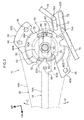
Fig. 2 is a side view showing the structure of main portions of a seat operating device that is provided at the vehicle seat, and is a drawing of a state in which a selector is positioned at one end of a range of movement; -
Fig. 3 is a side view showing a portion of the structure illustrated inFig. 2 ; -
Fig. 4 is a side view that corresponds toFig. 3 and shows a state in which the selector is positioned at another end of the range of movement; and -
Fig. 5 is a side view that corresponds toFig. 3 andFig. 4 and shows a state in which the selector is positioned intermediately in the range of movement. - A
seat operating device 10 and avehicle seat 12 relating to an embodiment of the present invention are described hereinafter with reference toFig. 1 through Fig. 5 . Note that arrow FR that is shown appropriately in the respective drawings indicates the front direction of thevehicle seat 12, and arrow UP indicates the upward direction of thevehicle seat 12. Further, in the present embodiment, the front-rear direction, the up-down direction and the width direction of thevehicle seat 12 coincide with the front-rear direction, the up-down direction and the width direction of the vehicle. - As shown in
Fig. 1 , the vehicle seat relating to the present embodiment is structured by a seatmain body 14 and theseat operating device 10. The seatmain body 14 is set on a top surface of an unillustrated vehicle body floor portion. The seatmain body 14 has aseat cushion frame 16 that structures the skeleton of a seat cushion, and aseat back frame 18 that structures the skeleton of a seat back. Respective seat pads that are not illustrated are mounted to theseat cushion frame 16 and theseat back frame 18, and surfaces of the respective seat pads are covered by seat skins that are not illustrated. A sliding mechanism 20, areclining mechanism 22, and a lifter mechanism 24 (all of which are adjusting mechanisms) are provided at this seatmain body 14. - The sliding mechanism 20 is an adjusting mechanism for adjusting the front-rear position of the seat
main body 14 with respect to the vehicle body floor portion, and is structured to includeslide rails 28 that are disposed beneath alower frame 26. At theslide rail 28, anupper rail 30, that is fixed to the lower end portion of thelower frame 26 that is provided at the seatmain body 14, is supported so as to be slidable in the seat front-rear direction by alower rail 32 that is fixed to the vehicle body floor portion. - The above-described sliding mechanism 20 is a locking-type adjusting mechanism, and has a lock mechanism that is not illustrated and that restricts the sliding of the
upper rails 30 with respect to thelower rails 32. At this lock mechanism, the aforementioned restricting (locking) is released due to alock releasing lever 34, that is axially-supported at theupper rail 30, being rotated in a lock releasing direction (the arrow A direction inFig. 1 ). Due thereto, there becomes a state in which theupper rails 30 can slide with respect to thelower rails 32, i.e., adjustment of the front-rear position of the seatmain body 14 with respect to the vehicle body floor portion is possible. - The reclining
mechanism 22 is an angle adjusting mechanism that inclinably connects the seat back to the seat cushion. The recliningmechanism 22 is provided between the rear end portion of theseat cushion frame 16 and the lower end portion of theseat back frame 18. This recliningmechanism 22 is a locking-type adjusting mechanism, and has a lock mechanism that is not illustrated and that restricts inclining of theseat back frame 18 with respect to theseat cushion frame 16. At this lock mechanism, the aforementioned restricting (locking) is released due to alock releasing lever 36 being rotated in a lock releasing direction (the arrow B direction inFig. 1 ). Due thereto, there becomes a state in which the reclining angle of theseat back frame 18 with respect to theseat cushion frame 16 can be adjusted in plural stages. - Further, a
spiral spring 38, that urges the seat backframe 18 in a direction of inclining forward, is provided between theseat cushion frame 16 and the seat backframe 18. Therefore, when load is not applied to the seat backframe 18 in the lock released state of thereclining mechanism 22, the seat backframe 18 inclines forward to a predetermined position with respect to theseat cushion frame 16. On the other hand, when load of a predetermined value or greater in rear direction is applied to the seat backframe 18 in the lock released state of thereclining mechanism 22, the seat backframe 18 inclines rearward with respect to theseat cushion frame 16. Further, when the operational force of thelock releasing lever 36 is released at an arbitrary angle of inclination, thereclining mechanism 22 reverts back to the locked state, and the seat backframe 18 is restrained such that inclining thereof is restricted. - The
lifter mechanism 24 is an adjusting mechanism for adjusting the seat surface height of the seat cushion, and is interposed between theseat cushion frame 16 and thelower frame 26, and connects the both. Thislifter mechanism 24 has afront side link 40 and a rear side link 42 that are connected to theseat cushion frame 16 and thelower frame 26 so as to rotate freely. Thefront side link 40 and therear side link 42, together with theseat cushion frame 16 and thelower frame 26, structure a four-link construction. - The above-described
lifter mechanism 24 is an operation-type adjusting mechanism, and has a pump-type lifter device (not illustrated) that is conventionally known. This pump-type lifter device is mounted to the side surface at the vehicle width direction outer side of theseat cushion frame 16, and has an input shaft whose axial direction runs along the seat width direction. When this input shaft is rotated, the rotational force of this input shaft is transmitted to the rear side link 42 via a pinion and lifter gears (not illustrated) that are mounted to theseat cushion frame 16. Due thereto, therear side link 42 and the front side link 40 rotate, and the height at which theseat cushion frame 16 is disposed with respect to thelower frame 26 is adjusted. Note that, in the present embodiment, the operational force that is needed in order to adjust thelifter mechanism 24 is set to be higher than the operational force that is needed in order to release the locking of the sliding mechanism 20 and thereclining mechanism 22. - The
seat operating device 10 is described next. - As shown in
Fig. 2 andFig. 3 , theseat operating device 10 is structured by abase bracket 46, an operation lever 48 (operation member), a firstclutch member 50, a secondclutch member 52, and a selector 54 (switching member). The respective structural elements are described hereinafter. - The
base bracket 46 is formed from a sheet metal material, and is mounted to the surface at outer side in the vehicle width direction of theseat cushion frame 16 in a state of covering the aforementioned pump-type lifter device from the seat width direction outer side. Thebase bracket 46 has aside wall portion 46A that faces theseat cushion frame 16 with a gap therebetween, and anupper wall portion 46B and a lower wall portion 46C that extend toward the seat width direction inner side from the upper and lower ends of theside wall portion 46A. Theside wall portion 46A is formed in a substantially circular shape as viewed from the seat width direction, and theupper wall portion 46B and the lower wall portion 46C are curved in circular arc shapes along the outer periphery of theside wall portion 46A. - Further, an
upper flange portion 46D extends toward the upper side from the end portion at the inner side in the seat width direction of theupper wall portion 46B. Alower flange portion 46E extends toward the lower side from the end portion at the inner side in the seat width direction of the lower wall portion 46C. Bolt holes 56 are formed in theupper flange portion 46D andlower flange portion 46E. Unillustrated bolts, that are inserted through these bolt holes 56, are passed-through theseat cushion frame 16 and are screwed-together with unillustrated nuts. Due thereto, thebase bracket 46 is fastened and fixed to theseat cushion frame 16. - A T-shaped
groove 58 that is substantially T-shaped is formed in the rear end portion of theside wall portion 46A of the above-describedbase bracket 46. Due to this T-shapedgroove 58 being formed, a pair ofstopper portions side wall portion 46A. Thesestopper portions seat cushion frame 16, and face one another in the direction of rotation of theoperation lever 48 that is described later. The end portions, at the sides that face one another, of thesestopper portions - Further, a boss portion 64 that is shaped as a cylindrical tube is provided concentrically at the central portion of the
side wall portion 46A of the above-describedbase bracket 46. A supportingshaft 68 is inserted-through the inner side of this boss portion 64. The supportingshaft 68 is fixed to the boss portion 64, and projects-out inner side and outer side in the seat width direction of theside wall portion 46A. The supportingshaft 68 is disposed coaxially with the input shaft of the aforementioned pump-type lifter device. Theoperation lever 48 is mounted to a portion of the supportingshaft 68 which portion is further toward outer side in the seat width direction from theside wall portion 46A. - The
operation lever 48 is formed in an elongated shape of a resin material, and is structured by abase portion 48A that is shaped as a cylindrical tube having a bottom and that opens toward inner side in the seat width direction, and anarm portion 48B that is tubular and extends toward the seat front side from thebase portion 48A. The tube interior of thisarm portion 48B communicates with the inner side of thebase portion 48A. Further, the supportingshaft 68 is rotatably inserted within an unillustrated boss portion that is provided at thebase portion 48A. Due thereto, theoperation lever 48 is rotatably supported at the supportingshaft 68, and is mounted to theseat cushion frame 16 via the supportingshaft 68 and thebase bracket 46. - An unillustrated spring for returning spans between the above-described
operation lever 48 and theseat cushion frame 16. Theoperation lever 48 is maintained at the neutral position illustrated inFig. 1 by the urging force of the spring for returning. Further, the firstclutch member 50 is mounted to a portion of the supportingshaft 68 which portion is further toward the inner side in the seat width direction from theside wall portion 46A. - The first
clutch member 50 is formed of a sheet metal material, and has amain body portion 50A that is formed in a substantial disc shape. Themain body portion 50A is disposed between theside wall portion 46A and the pump-type lifter device, in a state in which the plate thickness direction of themain body portion 50A runs along the seat width direction. A circular through-hole is formed in the central portion of themain body portion 50A, and the supportingshaft 68 is inserted-through this through-hole. Due thereto, the firstclutch member 50 can rotate around the supportingshaft 68 that is the center of rotation of theoperation lever 48, and is mounted to theseat cushion frame 16 via the supportingshaft 68 and thebase bracket 46. - A connecting
portion 50B extends from the rear end portion of themain body portion 50A toward the seat rear side and lower side. A pair of upper and lowerlong holes portion 50B. A lowerside connecting member 74, that is formed in an elongated shape by a rod, spans between thelong hole 72 and thelock releasing lever 34 of the above-described sliding mechanism 20. Oneend portion 74A and anotherend portion 74B in the longitudinal direction of this lowerside connecting member 74 are bent toward the inner side in the seat width direction. Theend portion 74A is inserted into thelong hole 72 so as to be able to rotate in thelong hole 72 and so as to be able to slide in the longitudinal direction of thelong hole 72. Theother end portion 74B is rotatably inserted in a circular hole that is formed in the upper end portion of thelock releasing lever 34. Theend portion 74A of the lowerside connecting member 74 is positioned at the front end portion of thelong hole 72 at usual times. - An upper
side connecting member 76, that is formed in an elongated shape by a rod, spans between thelong hole 70 and thelock releasing lever 36 of the above-describedreclining mechanism 22. Oneend portion 76A and anotherend portion 76B in the longitudinal direction of this upperside connecting member 76 are bent toward the inner side in the seat width direction. Theend portion 76A is inserted into thelong hole 70 so as to be able to rotate in thelong hole 70 and so as to be able to slide in the longitudinal direction of thelong hole 70. Theend portion 76B is rotatably inserted in a circular hole that is formed in one end portion of thelock releasing lever 36. Theend portion 76A of the upperside connecting member 76 is positioned at the rear end portion of thelong hole 70 at usual times. - Further, a first cut-out
portion 80 is formed in the rear end portion of themain body portion 50A, in a vicinity of the upper side of the connectingportion 50B. This first cut-outportion 80 opens toward the outer side in the rotation radial direction of the first clutch member 50 (here, the seat rear side that is opposite to the supporting shaft 68). At usual times, the first cut-outportion 80 faces the gap between the above-described pair ofstopper portions portion 80 corresponds to afirst selector pin 86 of theselector 54 that is described later. - The second
clutch member 52 is provided between themain body portion 50A of the above-described firstclutch member 50 and the pump-type lifter device. The secondclutch member 52 is formed in a disc shape of a sheet metal material, and is disposed in a state of being coaxial to the supportingshaft 68 and such that the plate thickness direction runs along the seat width direction. The secondclutch member 52 is connected coaxially with and so as to be rotate integrally with the input shaft of the pump-type lifter device. Therefore, when the secondclutch member 52 is rotated, the height at which theseat cushion frame 16 is disposed with respect to thelower frame 26 is adjusted. In this case, when the secondclutch member 52 is rotated in the arrow C direction inFig. 2 , theseat cushion frame 16 is displaced toward the upper side, and, when the secondclutch member 52 is rotated in the arrow D direction inFig. 2 , theseat cushion frame 16 is displaced toward the lower side. - A
peripheral wall portion 52A, that extends toward outer side in the seat width direction, is provided at the front end portion of the secondclutch member 52. A second cut-outportion 82 is formed in the front end portion of the secondclutch member 52. This second cut-outportion 82 opens toward the outer side in the rotation radial direction of the second clutch member 52 (here, the seat front side that is opposite to the supporting shaft 68). The second cut-outportion 82 corresponds to asecond selector pin 88 of theselector 54 that is described later. - The
selector 54 is formed in an elongated shape of, for example, a metal material, and is accommodated at the interior of theoperation lever 48 along the longitudinal direction of theoperation lever 48. Theselector 54 engages with plural supporting portions, not shown in the drawings, that are provided at theoperation lever 48, and is supported so as to be able to be operationally moved (so as to be able to be operationally slid) in an longitudinal direction (the rotation radial direction) of theoperation lever 48. Theselector 54 has arod portion 54A that is formed in an elongated shape. Aplate portion 54B that is plate-shaped is provided at one end portion in a longitudinal direction (the end portion at the seat rear side) of thisrod portion 54A. Further, anoperation button portion 54C that is solid cylindrical is provided at the other end portion in the longitudinal direction (the end portion at the seat front side) of therod portion 54A. Thisoperation button portion 54C is inserted-through a circular opening, that is formed in the distal end portion (the end portion at the seat front side) of anarm portion 48B, and projects-out further toward the seat front side than thearm portion 48B. - The
plate portion 54B is positioned at the outer side in the seat width direction from thebase bracket 46. Along hole 84, that is long along the longitudinal direction of theselector 54, is formed at a central portion in the longitudinal direction of theplate portion 54B. The supportingshaft 68 is inserted through thislong hole 84. Due thereto, theselector 54 is supported so as to be able to slide within a range of thelong hole 84 with respect to the supportingshaft 68. The first selector pin 86 (first engaging portion) and the second selector pin 88 (second engaging portion), that project-out toward inner side in the seat width direction, are provided at theplate portion 54B. - The
first selector pin 86 and thesecond selector pin 88 are positioned at mutually opposite sides across the supportingshaft 68 that is the center of rotation of theoperation lever 48. Theside wall portion 46A of thebase bracket 46, the firstclutch member 50 and the secondclutch member 52 are disposed between thefirst selector pin 86 and thesecond selector pin 88. - The
first selector pin 86 is formed in the shape of a long circle whose longitudinal direction runs substantially along the vertical direction. Both longitudinal direction end portions of the first selector pin 86 (the both end portions along the direction of rotation of the operation lever 48) are made to be circular arc shaped curved surfaces as seen from the seat width direction. Thefirst selector pin 86 is provided such that, in the state in which theselector 54 is positioned at a first operation position (the position shown inFig. 2 ) that is one end in the range of movement of theselector 54 with respect to theoperation lever 48, thefirst selector pin 86 fits-together (engages) with the first cut-outportion 80 of the firstclutch member 50. Further, the vertical direction dimension of thefirst selector pin 86 is set to be slightly smaller than the gap between the pair ofstopper portions first selector pin 86 can pass-through between the pair ofstopper portions - The
second selector pin 88 is formed in a rectangular shape whose longitudinal direction runs substantially along the vertical direction, and the both longitudinal direction end portions thereof (the both end portions along the direction of rotation of the operation lever 48) are formed in the shapes of flat surfaces. Note that the four corner portions of thesecond selector pin 88 are chamfered. Thesecond selector pin 88 is provided at theplate portion 54B such that, in the state in which theselector 54 is positioned at the first operation position shown inFig. 2 , thesecond selector pin 88 is disposed so as to be apart, toward the seat front side, from the second cut-outportion 82. - An unillustrated coil spring spans between the
selector 54 and theoperation lever 48 that are structured as described above. Theselector 54 is urged toward the front end side of theoperation lever 48 by this coil spring. Therefore, theselector 54 is usually maintained at the first operation position (one end of the range of movement) that is shown inFig. 1 andFig. 2 . - In the state in which the
selector 54 is positioned at the first operation position in this way, when thearm portion 48B of theoperation lever 48 is operated toward the upper side (one side) of the neutral position, the firstclutch member 50, at which thefirst selector pin 86 is fit-together with the first cut-outportion 80, is rotated in the arrow C direction inFig. 2 . Due thereto, the upperside connecting member 76 is pulled diagonally toward the seat front side and lower side, and thelock releasing lever 36 of thereclining mechanism 22 is rotated in the arrow B direction inFig. 1 . Due thereto, locking of thereclining mechanism 22 is released. In this case, since thelong hole 72 moves toward the front direction with respect to the oneend portion 74A in the longitudinal direction of the lowerside connecting member 74 and the oneend portion 74A relatively moves toward the rear direction in thelong hole 72, the operational force of theoperation lever 48 is not transmitted to the sliding mechanism 20. - Further, in the state in which the
selector 54 is positioned at the first operation position, when thearm portion 48B of theoperation lever 48 is operated toward the lower side (other side) of the neutral position, the firstclutch member 50, at which thefirst selector pin 86 is fit-together with the first cut-outportion 80, is rotated in the arrow D direction inFig. 2 . Due thereto, the lowerside connecting member 74 is pulled diagonally toward the seat rear side and upper side, and thelock releasing lever 34 of the sliding mechanism 20 is rotated in the arrow A direction inFig. 1 . Due thereto, locking of the sliding mechanism 20 is released. In this case, since thelong hole 70 moves toward the rear direction with respect to the oneend portion 76A in the longitudinal direction of the upperside connecting member 76 and the oneend portion 76A relatively moves toward the front direction in thelong hole 70, the operational force of theoperation lever 48 is not transmitted to thereclining mechanism 22. - On the other hand, when the
selector 54 is moved toward a second operation position that is the other end of the range of movement of theselector 54 due to theoperation button portion 54C being pushed-in toward theoperation lever 48 side, as shown inFig. 4 , thefirst selector pin 86 passes-through between the pair ofstopper portions first selector pin 86 with the first cut-outportion 80 is released. Further, at this time, thesecond selector pin 88 fits-together (engages) with the second cut-outportion 82 of the secondclutch member 52. In this fit-together state, the planar surfaces of the upper and lower ends of thesecond selector pin 86 face theperipheral wall portion 52A of the secondclutch member 52. - In this way, in the state in which the
selector 54 is positioned at the second operation position, when thearm portion 48B of theoperation lever 48 is operated toward the upper side of the neutral position, the secondclutch member 52, at which thesecond selector pin 88 is fit-together with the second cut-outportion 82, is rotated in the arrow C direction inFig. 4 integrally with the input shaft of the pump-type lifter device. Due thereto, the rotational force of this input shaft is transmitted to the rear side link 42 via the pinion and lifter gears, and theseat cushion frame 16 is displaced toward the upper side with respect to the lower frame 26 (the seat height is adjusted higher). - Further, in the state in which the
selector 54 is positioned at the second operation position, when thearm portion 48B of theoperation lever 48 is operated toward the lower side of the neutral position, the secondclutch member 52, at which thesecond selector pin 88 is fit-together with the second cut-outportion 82, is rotated in the arrow D direction inFig. 4 integrally with the input shaft of the pump-type lifter device. Due thereto, the rotational force of this input shaft is transmitted to the rear side link 42 via the pinion and lifter gears, and theseat cushion frame 16 is displaced toward the lower side with respect to the lower frame 26 (the seat height is adjusted lower). - Note that, in the state in which the
selector 54 is positioned at the first operation position, at the time when thearm portion 48B of theoperation lever 48 is operated toward the upper side and the lower side of the neutral position, interference between thefirst selector pin 86 and thebase bracket 46 is prevented due to thefirst selector pin 86 moving vertically within the T-shapedgroove 58. However, in a case in which theoperation button portion 54C of theselector 54 is pushed in the midst of this operation of theoperation lever 48, operation of theselector 54 toward the second operation position is restricted due to thefirst selector pin 86 abutting one of the pair ofstopper portions - Further, in the state in which the
selector 54 is positioned at the second operation position, at the time when thearm portion 48B of theoperation lever 48 is operated toward the upper side and the lower side of the neutral position, interference between thefirst selector pin 86 and thebase bracket 46 is prevented due to thefirst selector pin 86 moving vertically at the seat rear side of the pair ofstopper portions operation button portion 54C of theselector 54 is released in the midst of this operation of theoperation lever 48, movement of theselector 54 toward the first operation position is restricted due to thefirst selector pin 86 abutting one of the pair ofstopper portions - Further, in the present embodiment, at the time when the
arm portion 48B of theoperation lever 48 is operated toward the upper side and the lower side, a pair of upper and lowerload receiving portions side wall portion 46A of thebase bracket 46, and abutment portions, not illustrated in the drawings, that are provided at theoperation lever 48, abut one another. Due thereto, further operation of theoperation lever 48 is restricted. The shapes of the T-shapedgroove 58 and the pair ofstopper portions first selector pin 86 and thebase bracket 46 is prevented at this time as well. - Moreover, as shown in
Fig. 5 , in the state in which theselector 54 is positioned between the first operation position and the second operation position (intermediately in the range of movement), thefirst selector pin 86 is disposed between the pair ofstopper portions operation lever 48 is restricted due to thefirst selector pin 86 abutting the pair ofstopper portions operation lever 48. - Further, in the present embodiment, a dimension, that runs along the longitudinal direction (the moving operation direction) of the
selector 54, of thefirst selector pin 86, that fits-together with the first cut-outportion 80 of the firstclutch member 50, is set to be smaller than a dimension of thesecond selector pin 88 that fits-together with the second cut-outportion 82 of the secondclutch member 52. The strength of thefirst selector pin 86 is set on the basis of the operational force needed in order to release the locking of the sliding mechanism 20 and thereclining mechanism 22, and is set to be lower than the strength of thesecond selector pin 88 that is set on the basis of the operational force needed in order to adjust thelifter mechanism 24. Note that the strengths of thefirst selector pin 86 and thesecond selector pin 88 are set by the sectional moduli (the shape, thickness and the like) thereof and the materials thereof. - The operation and effects of the present embodiment are described next.
- In the present embodiment, the
operation lever 48 is mounted to the seatmain body 14 so as to be able to be rotatingly operated, and theselector 54 is mounted to theoperation lever 48 so as to be able to move in the rotation radial direction of theoperation lever 48. In the state in which theselector 54 is positioned at the first operation position, thefirst selector pin 86 that is provided at theselector 54 is fit-together with the first cut-outportion 80 of the first clutch member 50 (the state shown inFig. 2 andFig. 3 ). When, in this state, theoperation lever 48 is rotatingly operated, the firstclutch member 50 rotates integrally with theoperation lever 48, and the operational force of theoperation lever 48 is transmitted to the sliding mechanism 20 or thereclining mechanism 22 that are connected to the firstclutch member 50. - On the other hand, in the state in which the
selector 54 is positioned at the second operation position, thesecond selector pin 88 that is provided at theselector 54 is engaged with the second cut-outportion 82 of the second clutch member 52 (the state shown inFig. 4 ). When, in this state, theoperation lever 48 is rotatingly operated, the secondclutch member 52 rotates integrally with theoperation lever 48, and the operational force of theoperation lever 48 is transmitted to thelifter mechanism 24 that is connected to the secondclutch member 52. - In the present embodiment, the
first selector pin 86 and thesecond selector pin 88 of theselector 54 are positioned at mutually opposite sides across the supportingshaft 68 that is the center of rotation of the firstclutch member 50 and the secondclutch member 52. Further, the first cut-outportion 80 of the firstclutch member 50, with which thefirst selector pin 86 fits-together, and the second cut-outportion 82 of the secondclutch member 52, with which thesecond selector pin 88 fits-together, respectively open outwardly in the rotation radial directions of the respectiveclutch members clutch member 50 and the secondclutch member 52, and one selector pin is moved between this inwardly-facing cut-out portion and an outwardly-facing cut-out portion that is formed in the other clutch member, the one clutch member can be made to be compact. - Moreover, in the present embodiment, the shapes and the sizes of the
first selector pin 86 and thesecond selector pin 88 can respectively be selected individually in accordance with the needed operational forces of the sliding mechanism 20 and thereclining mechanism 22 that are connected to the firstclutch member 50, and thelifter mechanism 24 that is connected to the secondclutch member 52. Therefore, the flexibility for design can be improved. - Further, in the present embodiment, in a state in which the
selector 54 is positioned intermediately in the range of movement with respect to theoperation lever 48, i.e., in a state in the midst of operation of theselector 54, thefirst selector pin 86 that is provided at theselector 54 is disposed between the pair ofstopper portions seat cushion frame 16. In this state, rotational operation ofoperation lever 48 is restricted due to thefirst selector pin 86 abutting the pair ofstopper portions operation lever 48. Due thereto, erroneous operation which is caused by rotationally operating theoperation lever 48 in the midst of operation of theselector 54 can be prevented. - Moreover, in the present embodiment, the
operation lever 48 and the firstclutch member 50 are mounted to theseat cushion frame 16 via thebase bracket 46, and the pair ofstopper portions base bracket 46. Namely, thebase bracket 46, that is provided for mounting theoperation lever 48 and the first clutch member to the seatmain body 14, also has the function of restricting the rotational operation of theoperation lever 48 in the midst of the operation of theselector 54. Therefore, the number of parts can be reduced. - Further, in the present embodiment, the dimension, along the direction of the moving operation of the
selector 54, of thefirst selector pin 86, that is disposed between the pair ofstopper portions selector 54 is in the midst of being operated, is set to be smaller than that of thesecond selector pin 88. Due thereto, the amount of movement (the operation stroke) of theselector 54 that is needed in order for thefirst selector pin 86 to pass-through between the pair ofstopper portions selector 54 can be improved. - Note that, also at the seat adjusting device that was described in the Related Art section (hereinafter called the conventional example), it is preferable to provide a stopper for preventing erroneous operation so as to restrict operation of the operation lever in the midst of operation of the switching knob. However, when such a stopper for preventing erroneous operation is disposed between the reclining plate and the lifter plate in the conventional example, the operation stroke of the switching knob becomes long. Namely, when the stopper for preventing erroneous operation is formed to be small in order to make the stroke of the switching knob short, the strength of the stopper for preventing erroneous operation is insufficient. Therefore, the operation stroke of the switching knob must be made to be long. In this way, ensuring the strength of the stopper for preventing erroneous operation and shortening of the operation stroke of the switching knob (the selector) are contradictory requirements. However, in the present embodiment, such contradictory requirements can both be satisfied by the above-described structure.
- The above-described embodiment is structured such that the pair of
stopper portions first selector pin 86. However, the present invention is not limited to this, and may be structured such that a pair of stopper portions are provided at the side of the second selector pin 88 (the second engaging portion). - Further, the above-described embodiment is structured such that the sliding mechanism 20 and the
reclining mechanism 22 that serve as locking-type adjusting mechanisms are connected to the firstclutch member 50, and thelifter mechanism 24 that serves as an operation-type adjusting mechanism is connected to the secondclutch member 52. However, the present invention is not limited to this, and the types and numbers of the adjusting mechanisms that are connected to the first clutch member and the second clutch member can be changed appropriately. Further, adjusting mechanisms other than those described above, for example a lumbar support mechanism, a tilting mechanism, an ottoman mechanism, a side support mechanism, or the like, are included among the adjusting mechanisms that are connected to the first clutch member and the second clutch member. - Further, the above-described embodiment is structured such that the operation lever 48 (operation member) is mounted to the seat
main body 14 so as to be able to rotate around an axis that runs along the seat width direction. However, the present invention is not limited to this. It suffices for the operation lever to be a member that is mounted to the seat main body so as to be able to be rotatingly operated, and the direction of the rotational operation of the operation lever can be changed appropriately. - Further, although the above-described embodiment is structured such that the pair of
stopper portions base bracket 46, the present invention is not limited to this, and may be structured such that the pair of stopper portions are fixed to the seat main body separately from the base bracket. Further, there may be a structure in which the pair ofstopper portions - In addition, the present invention can be implemented by being modified in various ways within a scope that does not deviate from the gist thereof. Further, the scope of the present invention is, of course, not limited to the above-described embodiment.
Claims (5)
- A seat operating device comprising:an operation member that is mounted to a seat main body of a vehicle seat so as to be rotatingly operated;a first clutch member that is mounted to the seat main body so as to rotate around a rotational center of the operation member, and that is connected to an adjusting mechanism that the seat main body is equipped with, and in which is formed a first cut-out portion that opens outwardly in a rotation radial direction of the first clutch member;a second clutch member that is mounted to the seat main body so as to rotate around the rotational center of the operation member, and that is connected to another adjusting mechanism that the seat main body is equipped with, and in which a second cut-out portion, that opens outwardly in a rotation radial direction of the second clutch member, is formed at an opposite side of the first cut-out portion across the rotational center; anda switching member that is mounted to the operation member so as to be movingly operated in a rotation radial direction of the operation member, and that has a first engaging portion and a second engaging portion that are positioned at mutually opposite sides across the rotational center, and, in a state in which the switching member is positioned at one end of a range of movement of the switching member, the first engaging portion engages with the first cut-out portion, and, in a state in which the switching member is positioned at another end of the range of movement of the switching member, the second engaging portion engages with the second cut-out portion.
- The seat operating device of claim 1, further comprising a pair of erroneous operation preventing portions that are provided so as to be unable to be displaced with respect to the seat main body and that face one another in a direction of rotation of the operation member, and, in a state in which the switching member is positioned intermediately in the range of movement, one of the first engaging portion and the second engaging portion is disposed between the pair of erroneous operation preventing portions.
- The seat operating device of claim 2, further comprising a base bracket,
wherein the operation member and the first clutch member are mounted to the seat main body via the base bracket, and the pair of erroneous operation preventing portions are provided at the base bracket. - The seat operating device of claim 2 or claim 3, wherein a dimension, along a direction of movement of the switching member, of one of the first engaging portion and the second engaging portion is set to be smaller than a dimension of another of the first engaging portion and the second engaging portion.
- A vehicle seat comprising:a seat main body that is for seating of a passenger and at which a plurality of adjusting mechanisms are provided; andthe seat operating device of any one of claim 1 through claim 4 at which the operating member, the first clutch member and the second clutch member are mounted to the seat main body, and the adjusting mechanisms are connected to the first clutch member and the second clutch member respectively.
Applications Claiming Priority (1)
| Application Number | Priority Date | Filing Date | Title |
|---|---|---|---|
| JP2013077772A JP6186158B2 (en) | 2013-04-03 | 2013-04-03 | Seat operating device and vehicle seat |
Publications (1)
| Publication Number | Publication Date |
|---|---|
| EP2786894A1 true EP2786894A1 (en) | 2014-10-08 |
Family
ID=50396981
Family Applications (1)
| Application Number | Title | Priority Date | Filing Date |
|---|---|---|---|
| EP14162691.1A Withdrawn EP2786894A1 (en) | 2013-04-03 | 2014-03-31 | Seat operating device and vehicle seat |
Country Status (4)
| Country | Link |
|---|---|
| US (1) | US9174558B2 (en) |
| EP (1) | EP2786894A1 (en) |
| JP (1) | JP6186158B2 (en) |
| CN (1) | CN104097544B (en) |
Families Citing this family (4)
| Publication number | Priority date | Publication date | Assignee | Title |
|---|---|---|---|---|
| US9216667B1 (en) * | 2014-09-09 | 2015-12-22 | Ts Tech Co., Ltd. | Vehicle seat |
| JP6867841B2 (en) * | 2017-03-28 | 2021-05-12 | シロキ工業株式会社 | Seat reclining device |
| KR20230064716A (en) * | 2021-11-04 | 2023-05-11 | 현대자동차주식회사 | Device for adjusting seat of vehicle |
| JP7751506B2 (en) * | 2022-02-21 | 2025-10-08 | 日本発條株式会社 | Vehicle seats |
Citations (2)
| Publication number | Priority date | Publication date | Assignee | Title |
|---|---|---|---|---|
| JP2007196899A (en) * | 2006-01-27 | 2007-08-09 | Toyota Motor Corp | Sheet operating device and sheet |
| WO2013018869A1 (en) * | 2011-08-02 | 2013-02-07 | 日本発條株式会社 | Vehicle seat |
Family Cites Families (10)
| Publication number | Priority date | Publication date | Assignee | Title |
|---|---|---|---|---|
| JP4120078B2 (en) * | 1998-12-25 | 2008-07-16 | アイシン精機株式会社 | Walk-in device for vehicle seat |
| DE10015772C1 (en) * | 2000-03-30 | 2001-06-07 | Faure Bertrand Sitztech Gmbh | Seat position adjustment mechanism has a single hand lever which can be used selectively for coupling to one of two step gearings in a simple assembly |
| US6926364B2 (en) * | 2002-08-23 | 2005-08-09 | Faurecia Automotive Seating Canada Limited | Fold flat vehicle seat in rearward position |
| JP4459124B2 (en) * | 2005-07-14 | 2010-04-28 | 本田技研工業株式会社 | Folding vehicle seat |
| JP4185935B2 (en) * | 2006-01-27 | 2008-11-26 | トヨタ自動車株式会社 | Sheet |
| JP4224069B2 (en) * | 2006-01-27 | 2009-02-12 | トヨタ自動車株式会社 | Sheet |
| JP4182984B2 (en) * | 2006-01-27 | 2008-11-19 | トヨタ自動車株式会社 | Sheet |
| DE102006047398A1 (en) * | 2006-10-06 | 2008-05-21 | Lear Corporation, Southfield | 2-in-1-operating lever |
| US7712835B2 (en) * | 2008-04-23 | 2010-05-11 | Tachi-S Co., Ltd. | Structure of control portion of seat height adjuster |
| DE102012001278A1 (en) * | 2012-01-25 | 2013-07-25 | Gm Global Technology Operations, Llc | Adjustment system, motor vehicle seat, motor vehicle and method for this purpose |
-
2013
- 2013-04-03 JP JP2013077772A patent/JP6186158B2/en not_active Expired - Fee Related
-
2014
- 2014-03-31 EP EP14162691.1A patent/EP2786894A1/en not_active Withdrawn
- 2014-04-01 US US14/242,735 patent/US9174558B2/en not_active Expired - Fee Related
- 2014-04-02 CN CN201410132291.XA patent/CN104097544B/en not_active Expired - Fee Related
Patent Citations (2)
| Publication number | Priority date | Publication date | Assignee | Title |
|---|---|---|---|---|
| JP2007196899A (en) * | 2006-01-27 | 2007-08-09 | Toyota Motor Corp | Sheet operating device and sheet |
| WO2013018869A1 (en) * | 2011-08-02 | 2013-02-07 | 日本発條株式会社 | Vehicle seat |
Also Published As
| Publication number | Publication date |
|---|---|
| JP6186158B2 (en) | 2017-08-23 |
| JP2014201158A (en) | 2014-10-27 |
| CN104097544B (en) | 2017-10-31 |
| US20140300160A1 (en) | 2014-10-09 |
| US9174558B2 (en) | 2015-11-03 |
| CN104097544A (en) | 2014-10-15 |
Similar Documents
| Publication | Publication Date | Title |
|---|---|---|
| EP1894769B1 (en) | Seat height adjustment device for automobile | |
| EP1790522B1 (en) | Walk-in device | |
| EP1939032B1 (en) | Seat | |
| EP1942028B1 (en) | Seat | |
| EP1944192B1 (en) | Seat | |
| US20100133889A1 (en) | Pivoting headrest with cable operated release catch | |
| US20150090855A1 (en) | Vehicle seat | |
| CN106994922B (en) | Children's seat | |
| US8408510B2 (en) | Apparatus for preventing rotation of seat frame for vehicle | |
| HUE028087T2 (en) | Lockout mechanism for foldable head rest | |
| EP2786894A1 (en) | Seat operating device and vehicle seat | |
| EP2415630A2 (en) | Lifting mechanism of vehicle seat | |
| CN107791901B (en) | Reclining and sliding system for vehicle seat | |
| EP3523159B1 (en) | Infinite adjustment mechanism for a head restraint | |
| US9902296B2 (en) | Seatback drive system spring down, power up | |
| JP6562005B2 (en) | Entry / exit support structure for vehicle seats | |
| JP6724656B2 (en) | Vehicle seat | |
| JP3442689B2 (en) | Seat lifter and ratchet lever mechanism | |
| EP1859706A1 (en) | Reclining seat for automobile | |
| JP3762534B2 (en) | Headrest device | |
| JP6582508B2 (en) | Vehicle seat | |
| US9168847B2 (en) | Horizontal action seat tilt mechanism and bezel | |
| JP2018075955A (en) | Lumber support device of vehicle seat | |
| JP7192540B2 (en) | cushion frame | |
| JP2011098583A (en) | Reclining device for vehicle seat |
Legal Events
| Date | Code | Title | Description |
|---|---|---|---|
| PUAI | Public reference made under article 153(3) epc to a published international application that has entered the european phase |
Free format text: ORIGINAL CODE: 0009012 |
|
| 17P | Request for examination filed |
Effective date: 20140331 |
|
| AK | Designated contracting states |
Kind code of ref document: A1 Designated state(s): AL AT BE BG CH CY CZ DE DK EE ES FI FR GB GR HR HU IE IS IT LI LT LU LV MC MK MT NL NO PL PT RO RS SE SI SK SM TR |
|
| AX | Request for extension of the european patent |
Extension state: BA ME |
|
| R17P | Request for examination filed (corrected) |
Effective date: 20141104 |
|
| RBV | Designated contracting states (corrected) |
Designated state(s): AL AT BE BG CH CY CZ DE DK EE ES FI FR GB GR HR HU IE IS IT LI LT LU LV MC MK MT NL NO PL PT RO RS SE SI SK SM TR |
|
| RAP1 | Party data changed (applicant data changed or rights of an application transferred) |
Owner name: NHK SPRING CO., LTD. |
|
| GRAP | Despatch of communication of intention to grant a patent |
Free format text: ORIGINAL CODE: EPIDOSNIGR1 |
|
| RIN1 | Information on inventor provided before grant (corrected) |
Inventor name: SHIGEMATSU, RYOHEI Inventor name: YAGAME, HIROSHI Inventor name: HIRATA, TAKAFUMI Inventor name: OKAMURA, HIRONOBU Inventor name: NAKAMURA, TAKESHI Inventor name: NAKAZONO, MIHO |
|
| INTG | Intention to grant announced |
Effective date: 20160629 |
|
| STAA | Information on the status of an ep patent application or granted ep patent |
Free format text: STATUS: THE APPLICATION IS DEEMED TO BE WITHDRAWN |
|
| 18D | Application deemed to be withdrawn |
Effective date: 20161110 |