EP2786841A1 - Screw driver for collated screws and screw feeding machanism of screw driver - Google Patents
Screw driver for collated screws and screw feeding machanism of screw driver Download PDFInfo
- Publication number
- EP2786841A1 EP2786841A1 EP20140001214 EP14001214A EP2786841A1 EP 2786841 A1 EP2786841 A1 EP 2786841A1 EP 20140001214 EP20140001214 EP 20140001214 EP 14001214 A EP14001214 A EP 14001214A EP 2786841 A1 EP2786841 A1 EP 2786841A1
- Authority
- EP
- European Patent Office
- Prior art keywords
- screw
- arm member
- nose part
- guide
- feeding operation
- Prior art date
- Legal status (The legal status is an assumption and is not a legal conclusion. Google has not performed a legal analysis and makes no representation as to the accuracy of the status listed.)
- Withdrawn
Links
Images





Classifications
-
- B—PERFORMING OPERATIONS; TRANSPORTING
- B25—HAND TOOLS; PORTABLE POWER-DRIVEN TOOLS; MANIPULATORS
- B25B—TOOLS OR BENCH DEVICES NOT OTHERWISE PROVIDED FOR, FOR FASTENING, CONNECTING, DISENGAGING, OR HOLDING
- B25B23/00—Details of, or accessories for, spanners, wrenches, screwdrivers
- B25B23/02—Arrangements for handling screws or nuts
- B25B23/04—Arrangements for handling screws or nuts for feeding screws or nuts
- B25B23/045—Arrangements for handling screws or nuts for feeding screws or nuts using disposable strips or discs carrying the screws or nuts
Definitions
- the invention relates to a screw driver and a screw feeding mechanism configured to sequentially feed collated screws to a driving position, the collated screws being a plurality of screws connected by a connecting band.
- a nose part is pushed in when pressed onto a workpiece, and in conjunction with this pushing-in operation, a feeding operation of collated screws and a driving operation of the collated screws are performed.
- an arm rotates in conjunction with the operating of pushing-in the nose part and a wheel is rotated by the rotation of the arm, so that a screw is delivered one by one.
- the nose part is further pushed in, the delivered screw is expelled by a bit and the screw is tightened and is driven in the workpiece by the rotating bit.
- the driving operation is completed, the nose part is returned to a standby position by a force of a spring that is provided in the screw driver.
- the screw driver is used so as to drive a screw in a gypsum board or concrete, it is not possible to prevent dust generated upon the driving from being introduced into the machine.
- a screw feeding mechanism is arranged at a position close to the driving position, the gypsum powders may be accumulated therein.
- the spring most comes close to a free length thereof and the resistance is increased because a bending part for rotating the arm is provided. That is, just before the return of the nose part is completed, the force of the spring is weakened and the sliding resistance is increased. For this reason, a return failure that the nose part is stopped without completely returning to the standby position may be caused.
- An object of the invention is to provide a screw feeding mechanism of a screw driver in which an increase in sliding resistance at the time of sliding a nose part is avoided, thereby avoiding a return failure without increasing a spring load.
- a screw feeding mechanism of a screw driver is provided.
- the screw feeding mechanism is configured to sequentially feed collated screws to a driving position.
- the collated screws are plurality of screws connected by a connecting band.
- the screw feeding mechanism includes a base part and a nose part provided on the base part in a slidable manner.
- the nose part includes a wheel member provided in a rotatable manner and an arm member connected to the wheel member.
- the base part includes a guide member having a guide portion configured to guide a movement of the arm member when the nose part slides.
- a sliding of the nose part causes a feeding operation in which the wheel member is rotated by the movement of the arm member and the rotated wheel member is engaged with the collated screws to feed the collated screws.
- a further sliding of the nose part by a pushing-in of the nose part after the feeding operation causes a driving operation in which a leading screw and a driver bit are engaged with each other to drive the leading screw.
- the arm member is configured and arranged to vibrate or to rotate in conjunction with at least one of the feeding operation and the driving operation.
- the arm member performs an unloaded feeding operation, by which the screw is not fed, in conjunction with at least one of the feeding operation and the driving operation.
- the arm member is configured to vibrate or to rotate after the feeding operation.
- the guide portion includes a non-parallel guide section configured to guide the movement of the arm member in a direction not parallel to the sliding direction of the nose part so as to vibrate or to rotate the arm member after the feeding operation.
- a position at which the arm member and the guide portion engage with each other during the driving operation is, when viewed from a direction perpendicular to the sliding direction of the nose part, between a position at which the arm member and the guide portion engage with each other at the start of the feeding operation and a position at which the arm member and the guide portion engage with each other at the end of the feeding operation.
- a screw driver for collated screws is provided.
- the screw driver includes the screw feeding mechanism described above.
- the arm member is configured to vibrate or to rotate in conjunction with at least one of the feeding operation and the driving operation. Therefore, it is possible to shake off or sweep dust attached to the arm member or to the guide member, thereby avoiding an increase in sliding resistance. Accordingly, it is possible to avoid a return failure without increasing a spring load, so that an operating load of the driving operation need not be increased.
- the arm member performs an unloaded feeding operation, by which a screw is not fed, in conjunction with at least one of the feeding operation and the driving operation.
- the unloaded feeding operation it is possible to shake off or sweep the dust attached to the arm member or to the guide member, and therefore, an increase in the sliding resistance can be avoided.
- the arm member is configured to vibrate or to rotate after the feeding operation. Therefore, it is possible to shake off or sweep the dust attached to the arm member or to the guide member by using a relatively high spring load (since the spring is not completely extended, a force of the spring is relatively high). Also, after the dusts are shaken off, the nose part is returned by the spring. Therefore, since the dust have been already shaken off just before the return completion where the force of the spring is weakened and the sliding resistance is increased, it is possible to reduce the sliding resistance in a section where a problem is most apt to occur.
- the guide portion has the non-parallel guide section configured to guide the movement of the arm member in a direction not parallel to the sliding direction of the nose part so as to vibrate or to rotate the arm member after the feeding operation. Therefore, it is possible to shake off or sweep the dust attached to the arm member or guide member just by moving the arm member along the non-parallel guide section.
- the position at which the arm member and the guide portion engage with each other during the driving operation is, when viewed from the direction perpendicular to the sliding direction of the nose part, between the position at which the arm member and the guide portion engage with each other at the start of the feeding operation and the position at which the arm member and the guide portion engage with each other at the end of the feeding operation.
- the position at which the arm member and the guide portion engage with each other during the driving operation is the same as the position at which the arm member and the guide portion engage with each other at the end of the feeding operation with respect to the direction perpendicular to the sliding direction of the nose part, it is possible to reduce an attaching amount of the dust influencing the return of the nose part. That is, the sliding resistance when the arm member is moved in an upper-lower direction (the direction perpendicular to the sliding direction of the nose part) along the guide portion just before the return completion highly influences the return of the nose part.
- the arm member is caused to stay at the intermediate position during the driving operation (i.e., when the dusts are generated). Therefore, since it is possible to reduce an amount of the dust to be attached at the intermediate position, it is possible to prevent the sliding resistance from being increased when the arm member is vertically moved.
- a screw driver 10 uses collated screws 50, the collated screws being a plurality of screws 51 connected by a connecting band 52.
- the screw driver 10 has a tool main body 11 and a fastener supply device 20 that is mounted to the tool main body 11.
- a distal end of the tool main body 11 is provided with a mounting part 12.
- a connection part 21 a provided at a rear end of the fastener supply device 20 is configured so that it is fitted onto the mounting part 12. Thereby, the fastener supply device 20 can be attached to and detached from the tool main body 11.
- the tool main body 11 has a bit mounting part 15 at the tip thereof that is covered by the fastener supply device 20, and a driver bit 16 is mounted to the bit mounting part 15.
- a motor (not shown) that uses a battery 14 as a drive source is rotated.
- the nose part 30 is pressed onto a workpiece while the motor is rotated, the nose part 30 is pushed in the workpiece, so that the driver bit 16 collides with the screw 51 held at the nose part 30 and the driver bit 16 is pushed in. Since the rotation of the motor is transmitted to the pushed-in driver bit 16, the driver bit 16 is rotated, so that the screw 51 is tightened and driven in the workpiece.
- the fastener supply device 20 has a screw feeding mechanism that sequentially feeds the collated screws 50 to a driving position. As shown in Fig. 4 , the fastener supply device 20 has a base part 21 fixed to the distal end of the tool main body 11, the nose part 30 provided at a distal end of the base part 21 in a slidable manner and a spring 40 biasing the nose part 30 in a protruding direction with respect to the base part 21.
- the base part 21 has a connection part 21 a and the connection part 21 a is rotatably engaged with the mounting part 12 provided at the distal end of the tool main body 11, so that the tool main body 11 and the fastener supply device 20 can be connected to each other.
- the base part 21 has a square tube-shaped base casing 22, a plate-shaped guide member 24 that is fixed at an inner side of the base casing 22 and a magazine 23 fixed to a lower part of the base casing 22 and guides the collated screws 50.
- the nose part 30 has a base part 31 that can slide in the base casing 22 and a tip arm 32 that protrudes in a tip direction of the base part 31.
- a distal end of the base part 31 is formed with a holding recess 31 a extending continuously in a vertical direction.
- the holding recess 31 a is configured to allow the connecting band 52 of the collated screws 50 to pass therethrough such that, when feeding the collated screws 50, the connecting band 52 of the fed collated screws 50 is introduced through a lower opening of the holding recess 31 a and goes through an upper opening thereof.
- Slits 31b are formed at the front and rear of the holding recess 31 a.
- the driver bit 16 is introduced into the holding recess 31 a through the rear slit 31 b and pushes out the screw 51 held in the holding recess 31a, and the pushed out screw 51 is struck out from the front slit 31 b.
- the tip arm 32 is fixed to the distal end of the base part 31 and has a substantial L shape, when seen from a plan view.
- the tip arm 32 has a contact part 32a at a tip thereof.
- the contact part 32a abuts on the workpiece when the nose part 30 is pressed onto the workpiece.
- the contact part 32a of this embodiment is provided with a configuration of receiving a distal end of the screw 51 fed by the screw feeding mechanism and is formed with an ejection port 32b for driving-guiding the screw 51.
- the nose part 30 (the contact part 32a) is pressed onto the workpiece with the trigger 13 being pulled. By this operation, the nose part 30 is pushed into the base part 21. In conjunction with this operation, a feeding operation of the collated screws 50 and a driving operation of the collated screws 50 are performed.
- a mechanism as shown in Fig. 4 is arranged in the fastener supply device 20, so that the collated screws 50 are sequentially fed to the driving position.
- the mechanism has a wheel member 33 that is rotatably axis-supported by the base part 31, a wheel-side ratchet member 34 fixed to the wheel member 33, an arm-side ratchet member 35 having a side surface arranged to face the wheel-side ratchet member 34, a coil spring 36 that urges the wheel-side ratchet member 34 and the arm-side ratchet member 35 to come close to each other, an arm member 37 fixed to the arm-side ratchet member 35, a roller shaft 39 that is provided at a distal end of the arm member 37 and a roller 38 that is rotatably supported by the roller shaft 39.
- the wheel member 33 is a pair of members rotatably supported in the nose part 30.
- An outer periphery of the wheel member 33 is formed with teeth, which are engaged with notches 52a of the connecting band 52 of the collated screws 50, at the same interval as the notches 52a.
- the wheel member 33 is arranged at a position at which it is engaged with the notch 52a, and is configured to feed the collated screws 50 in an upper direction as it is rotated in a feeding direction (a clockwise direction in Fig. 5 ).
- the wheel-side ratchet member 34, the arm-side ratchet member 35 and the coil spring 36 configure a one-way clutch, and the wheel member 33 is rotated only in the feeding direction by the corresponding members.
- connecting surfaces of the wheel-side ratchet member 34 and the arm-side ratchet member 35 are formed with ratchet teeth that can be engaged with each other, and the wheel-side ratchet member 34 and the arm-side ratchet member 35 are urged and closely contacted to each other by the coil spring 36. For this reason, when the arm-side ratchet member 35 is rotated in the feeding direction (the clockwise direction in Fig.
- the arm member 37 has a shaft part 37b serving as a rotation support point and an arm part 37d that extends in a direction perpendicular to the shaft part 37b.
- a part of an outer periphery of the shaft part 37b is formed with a square column part 37c and the square column part 37c is fitted and fixed in a square hole 35a of the arm-side ratchet member 35.
- the arm member 37 is fixed so that it is rotated coaxially and integrally with the arm-side ratchet member 35.
- a distal end of the arm part 37d is provided with a roller support hole 37a, so that the roller shaft 39 can be fixed therein.
- the roller 38 is rotatably attached to the roller shaft 39, so that it is provided at a distal end of the arm member 37.
- the guide member 24 has a guide portion 24a along which the roller 38 is moved.
- the guide portion 24a is provided by forming a slot through the guide member 24, the slot having substantially the same width as the roller 38.
- the guide portion 24a is downwardly inclined at a sharp angle in the vicinity of a leading end portion seen from the standby position, is then upwardly inclined at a gentle angle and is then substantially parallel with the sliding direction of the nose part 30.
- the part that is downwardly inclined at a sharp angle is a feeding operation section S1 in which the feeding operation of rotating the wheel member 33 in the feeding direction to feed the collated screws 50 is performed.
- the part continuing to the feeding operation section S1 is a driving operation section S2 in which the driving operation of engaging the screw 51 and the driver bit 16 to thus drive a leading screw 51 is performed.
- the driving operation section S2 has a non-parallel guide section S2a that is inclined relative to the sliding direction of the nose part 30 and a parallel guide section S2b that is substantially parallel with the sliding direction of the nose part 30.
- the arm member 37 When the roller 38 is moved in the feeding operation section S1 of the guide portion 24a, the arm member 37 is largely downwardly inclined (refer to Fig. 7 ). As the arm member 37 is inclined, the arm-side ratchet member 35 is rotated by a predetermined angle and the wheel-side ratchet member 34 and the wheel member 33 are also rotated by a predetermined angle (by an interval of the notches 52a of the connecting band 52 of the collated screws 50) in conjunction with the arm-side ratchet member 35. Thereby, the wheel member 33 is rotated in the feeding direction, thereby feeding the collated screws 50 one by one.
- the nose part 30 is returned to the standby position by the biasing force of the spring 40 (refer to Fig. 6 ).
- the roller 38 is returned to the position before the feeding operation along the guide portion 24a.
- this operation is not transmitted due to an operation of the one-way clutch, so that it does not influence the rotation of the wheel member 33.
- the non-parallel guide section S2a of the driving operation section S2 of the guide portion 24a is to vibrate or to rotate the arm member 37 after the feeding operation. That is, if the non-parallel guide section S2a is not provided, the roller 38 straightly passes through the guide portion 24a of the driving operation section S2 without any resistance. However, in this embodiment, the non-parallel guide section S2a is provided, so that the roller 38 passing through the guide portion 24a of the driving operation section S2 is caused to vertically move and the arm member 37 is thus rotated. Also, the driving operation section S2 is configured so that the roller 38 passing through the guide portion 24a collides with an edge of the guide portion 24a and the arm member 37 is thus vibrated.
- a position C of the roller 38 during the driving operation is varies within a range between a position A of the roller 38 at the start of the feeding operation and a position B of the roller 38 at the end of the feeding operation. That is, during the driving operation, the roller 38 is in a condition like standing by at a half-returned position.
- the arm member 37 is caused to vibrate or to rotate in conjunction with at least one of the feeding operation and the driving operation, it is possible to shake off or sweep dust attached to the arm member 37 or to the guide member 24. Also, since it is possible to avoid a return failure without increasing the load of the spring 40, an operating load of the driving operation is not increased.
- the arm member 37 is caused to vibrate or to rotate after the feeding operation, it is possible to shake off or sweep the dust attached to the arm member 37 or guide member 24 by using a load, which is generated by the pressing upon the driving, or a relatively high spring load (a load that is generated by the spring 40 at a state where the spring 40 is not completely extended and a relatively high load can be thus generated).
- a load which is generated by the pressing upon the driving
- a relatively high spring load a load that is generated by the spring 40 at a state where the spring 40 is not completely extended and a relatively high load can be thus generated.
- the nose part 30 is returned by the spring 40. Therefore, since the dust have been already shaken off just before the return completion where the force of the spring 40 is weakened and the sliding resistance is increased, it is possible to reduce the sliding resistance in a section where a problem is most apt to occur.
- the guide portion 24a has the non-parallel guide section S2a configured to guide the movement of the roller 38 in a direction not parallel to the sliding direction of the nose part 30 so as to vibrate or to rotate the arm member 37 after the feeding operation. For this reason, it is possible to shake off or sweep the dust attached to the arm member 37 or guide member 24 just by moving the roller 38 along the non-parallel guide section S2a.
- the position C of the roller 38 during the driving operation is between the position A of the roller 38 at the start of the feeding operation and the position B of the roller 38 at the end of the feeding operation.
- the vertical position C of the roller 38 during the driving operation is the same as the vertical position B of the roller 38 at the end the feeding operation, since a range in which the dust is attached to influence the return of the nose part is reduced as a distance to the vertical position A is reduced, it is possible to reduce a amount of the dust influencing the return of the nose part 30.
- the sliding resistance when the roller 38 is vertically moved just before the return completion highly influences the return of the nose part 30.
- the roller 38 is caused to stay at an intermediate position during the driving operation (i.e., when the dusts are generated). Therefore, since it is possible to reduce a total amount of the dust to be attached on a moving path of the roller 38 upon the return, it is possible to prevent the sliding resistance from being increased when the roller 38 is vertically moved.
- the arm member 37 is caused to vibrate or to rotate in conjunction with the driving operation.
- the invention is not limited thereto.
- the arm member 37 may be caused to vibrate or to rotate, irrespective of the feeding operation.
- the arm member 37 is caused to vibrate or to rotate in accordance with the shape of the guide portion 24a.
- the invention is not limited thereto.
- a vibration or rotation means that directly applies the vibration of the motor to the arm member 37 may be provided.
- the shape of the guide portion 24a is not limited to the above embodiment and a variety of shapes are possible.
- a wave shape enabling the roller 38 to move in the up-down direction and in the left-right direction with a small pitch is also possible.
- the arm member 37 may be caused to vibrate or to rotate in accordance with the movement of the roller 38.
- the linear guide portion 24a may be provided with protrusions 24b or concave portions 24c so that the roller 38 collides with the same.
- the roller 38 that is moved along the guide portion 24a is caused to vibrate by the unevenness of the protrusions 24b or concave portions 24c., so that it is possible to vibrate the arm member 37.
- a side of the guide member 24 may be provided with convex portions 24d in a thickness direction.
- a side of the wheel member 33 may be formed with unevenness.
- concave portions 33a are formed at positions facing the arm member 37 and a side of the arm member 37 is formed with convex portions at positions facing the wheel member 33.
- an unloaded feeding operation by which a screw is not fed, may be performed and the arm member 37 may be caused to vibrate or to rotate by the unloaded feeding operation.
Landscapes
- Engineering & Computer Science (AREA)
- Mechanical Engineering (AREA)
- Portable Nailing Machines And Staplers (AREA)
- Details Of Spanners, Wrenches, And Screw Drivers And Accessories (AREA)
- Jigging Conveyors (AREA)
Abstract
Description
- The invention relates to a screw driver and a screw feeding mechanism configured to sequentially feed collated screws to a driving position, the collated screws being a plurality of screws connected by a connecting band.
- According to a screw driver disclosed in
JP2006-305671A - Since the screw driver is used so as to drive a screw in a gypsum board or concrete, it is not possible to prevent dust generated upon the driving from being introduced into the machine. In particular, since a screw feeding mechanism is arranged at a position close to the driving position, the gypsum powders may be accumulated therein.
- When the gypsum powders are accumulated in the screw feeding mechanism, a sliding resistance is increased upon sliding of the nose part. Therefore, the nose part cannot be completely returned to the standby position after the driving operation is completed, so that the next screw feeding may not be correctly performed.
- In particular, just before the return of the nose part to the standby position is completed, the spring most comes close to a free length thereof and the resistance is increased because a bending part for rotating the arm is provided. That is, just before the return of the nose part is completed, the force of the spring is weakened and the sliding resistance is increased. For this reason, a return failure that the nose part is stopped without completely returning to the standby position may be caused.
- When a spring load is increased, it may be possible to avoid the return failure even when the sliding resistance is increased. However, when the spring load is increased, a high force is required to push-in the nose part, so that an operating load of the driving operation is increased.
- An object of the invention is to provide a screw feeding mechanism of a screw driver in which an increase in sliding resistance at the time of sliding a nose part is avoided, thereby avoiding a return failure without increasing a spring load.
- According to a first aspect of the invention, a screw feeding mechanism of a screw driver is provided. The screw feeding mechanism is configured to sequentially feed collated screws to a driving position. The collated screws are plurality of screws connected by a connecting band. The screw feeding mechanism includes a base part and a nose part provided on the base part in a slidable manner. The nose part includes a wheel member provided in a rotatable manner and an arm member connected to the wheel member. The base part includes a guide member having a guide portion configured to guide a movement of the arm member when the nose part slides. A sliding of the nose part causes a feeding operation in which the wheel member is rotated by the movement of the arm member and the rotated wheel member is engaged with the collated screws to feed the collated screws. A further sliding of the nose part by a pushing-in of the nose part after the feeding operation causes a driving operation in which a leading screw and a driver bit are engaged with each other to drive the leading screw. The arm member is configured and arranged to vibrate or to rotate in conjunction with at least one of the feeding operation and the driving operation.
- According to a second aspect of the invention, the arm member performs an unloaded feeding operation, by which the screw is not fed, in conjunction with at least one of the feeding operation and the driving operation.
- According to a third aspect of the invention, the arm member is configured to vibrate or to rotate after the feeding operation.
- According to a fourth aspect of the invention, the guide portion includes a non-parallel guide section configured to guide the movement of the arm member in a direction not parallel to the sliding direction of the nose part so as to vibrate or to rotate the arm member after the feeding operation.
- According to a fifth aspect of the invention, a position at which the arm member and the guide portion engage with each other during the driving operation is, when viewed from a direction perpendicular to the sliding direction of the nose part, between a position at which the arm member and the guide portion engage with each other at the start of the feeding operation and a position at which the arm member and the guide portion engage with each other at the end of the feeding operation.
- According to a sixth aspect of the invention, a screw driver for collated screws is provided. The screw driver includes the screw feeding mechanism described above.
- According to the first aspect of the invention, the arm member is configured to vibrate or to rotate in conjunction with at least one of the feeding operation and the driving operation. Therefore, it is possible to shake off or sweep dust attached to the arm member or to the guide member, thereby avoiding an increase in sliding resistance. Accordingly, it is possible to avoid a return failure without increasing a spring load, so that an operating load of the driving operation need not be increased.
- According to the second aspect of the invention, the arm member performs an unloaded feeding operation, by which a screw is not fed, in conjunction with at least one of the feeding operation and the driving operation. By the unloaded feeding operation, it is possible to shake off or sweep the dust attached to the arm member or to the guide member, and therefore, an increase in the sliding resistance can be avoided.
- According to the third aspect of the invention, the arm member is configured to vibrate or to rotate after the feeding operation. Therefore, it is possible to shake off or sweep the dust attached to the arm member or to the guide member by using a relatively high spring load (since the spring is not completely extended, a force of the spring is relatively high). Also, after the dusts are shaken off, the nose part is returned by the spring. Therefore, since the dust have been already shaken off just before the return completion where the force of the spring is weakened and the sliding resistance is increased, it is possible to reduce the sliding resistance in a section where a problem is most apt to occur.
- According to the fourth aspect of the invention, the guide portion has the non-parallel guide section configured to guide the movement of the arm member in a direction not parallel to the sliding direction of the nose part so as to vibrate or to rotate the arm member after the feeding operation. Therefore, it is possible to shake off or sweep the dust attached to the arm member or guide member just by moving the arm member along the non-parallel guide section.
- According to the fifth aspect of the invention, the position at which the arm member and the guide portion engage with each other during the driving operation is, when viewed from the direction perpendicular to the sliding direction of the nose part, between the position at which the arm member and the guide portion engage with each other at the start of the feeding operation and the position at which the arm member and the guide portion engage with each other at the end of the feeding operation. According to this configuration, as compared with a configuration in which the position at which the arm member and the guide portion engage with each other during the driving operation is the same as the position at which the arm member and the guide portion engage with each other at the end of the feeding operation with respect to the direction perpendicular to the sliding direction of the nose part, it is possible to reduce an attaching amount of the dust influencing the return of the nose part. That is, the sliding resistance when the arm member is moved in an upper-lower direction (the direction perpendicular to the sliding direction of the nose part) along the guide portion just before the return completion highly influences the return of the nose part. However, according to the invention, the arm member is caused to stay at the intermediate position during the driving operation (i.e., when the dusts are generated). Therefore, since it is possible to reduce an amount of the dust to be attached at the intermediate position, it is possible to prevent the sliding resistance from being increased when the arm member is vertically moved.
- According to the sixth aspect of the invention, it is possible to provide a screw driver having the screw feeding mechanism with the above advantageous effects.
-
-
Fig. 1 is a perspective view of an external appearance of a screw driver. -
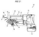
Fig. 2 is a side view of the screw driver. -
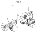
Fig. 3 is a perspective view of the external appearance of the screw driver with a fastener supply device being detached from a tool main body. -
Fig. 4 illustrates an internal structure of the fastener supply device. -
Fig. 5 is an exploded view showing a structure of rotating a wheel member of a screw feeding mechanism. -
Fig. 6 illustrates the internal structure of the fastener supply device before a feeding operation. -
Fig. 7 illustrates the internal structure of the fastener supply device after the feeding operation. -
Fig. 8 illustrates the internal structure of the fastener supply device after a driving operation. -
Fig. 9 shows a change in a position of a roller by the feeding operation and the driving operation. -
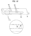
Fig. 10 is a side view of a guide member according to a first modified embodiment. -
Fig. 11A is a plan view of a guide member according to a second modified embodiment. -
Fig. 11B is a side view of the guide member shown inFig. 11A . -
Fig. 12A is a side view of a wheel member according to a third modified embodiment. -
Fig. 12B is a sectional view of the wheel member shown inFig. 12A . - Embodiments of the invention will be described with reference to the drawings.
- A
screw driver 10 according to this embodiment uses collatedscrews 50, the collated screws being a plurality ofscrews 51 connected by a connectingband 52. As shown inFigs. 1 to 3 , thescrew driver 10 has a toolmain body 11 and afastener supply device 20 that is mounted to the toolmain body 11. A distal end of the toolmain body 11 is provided with a mountingpart 12. Aconnection part 21 a provided at a rear end of thefastener supply device 20 is configured so that it is fitted onto the mountingpart 12. Thereby, thefastener supply device 20 can be attached to and detached from the toolmain body 11. - As shown in
Fig. 3 , the toolmain body 11 has abit mounting part 15 at the tip thereof that is covered by thefastener supply device 20, and adriver bit 16 is mounted to thebit mounting part 15. When atrigger 13 of the toolmain body 11 is pulled, a motor (not shown) that uses abattery 14 as a drive source is rotated. When anose part 30 is pressed onto a workpiece while the motor is rotated, thenose part 30 is pushed in the workpiece, so that thedriver bit 16 collides with thescrew 51 held at thenose part 30 and thedriver bit 16 is pushed in. Since the rotation of the motor is transmitted to the pushed-indriver bit 16, thedriver bit 16 is rotated, so that thescrew 51 is tightened and driven in the workpiece. - The
fastener supply device 20 has a screw feeding mechanism that sequentially feeds the collated screws 50 to a driving position. As shown inFig. 4 , thefastener supply device 20 has abase part 21 fixed to the distal end of the toolmain body 11, thenose part 30 provided at a distal end of thebase part 21 in a slidable manner and aspring 40 biasing thenose part 30 in a protruding direction with respect to thebase part 21. - The
base part 21 has aconnection part 21 a and theconnection part 21 a is rotatably engaged with the mountingpart 12 provided at the distal end of the toolmain body 11, so that the toolmain body 11 and thefastener supply device 20 can be connected to each other. As shown inFig. 4 , thebase part 21 has a square tube-shapedbase casing 22, a plate-shapedguide member 24 that is fixed at an inner side of thebase casing 22 and amagazine 23 fixed to a lower part of thebase casing 22 and guides the collated screws 50. - As shown in
Fig. 4 , thenose part 30 has abase part 31 that can slide in thebase casing 22 and atip arm 32 that protrudes in a tip direction of thebase part 31. - As shown in
Figs. 1 and4 , a distal end of thebase part 31 is formed with a holdingrecess 31 a extending continuously in a vertical direction. The holdingrecess 31 a is configured to allow the connectingband 52 of the collated screws 50 to pass therethrough such that, when feeding the collated screws 50, the connectingband 52 of the fed collatedscrews 50 is introduced through a lower opening of the holdingrecess 31 a and goes through an upper opening thereof.Slits 31b are formed at the front and rear of the holdingrecess 31 a. Thedriver bit 16 is introduced into the holdingrecess 31 a through therear slit 31 b and pushes out thescrew 51 held in the holdingrecess 31a, and the pushed outscrew 51 is struck out from the front slit 31 b. - The
tip arm 32 is fixed to the distal end of thebase part 31 and has a substantial L shape, when seen from a plan view. Thetip arm 32 has acontact part 32a at a tip thereof. Thecontact part 32a abuts on the workpiece when thenose part 30 is pressed onto the workpiece. Thecontact part 32a of this embodiment is provided with a configuration of receiving a distal end of thescrew 51 fed by the screw feeding mechanism and is formed with anejection port 32b for driving-guiding thescrew 51. - When driving the
screw 51 by thescrew driver 10, the nose part 30 (thecontact part 32a) is pressed onto the workpiece with thetrigger 13 being pulled. By this operation, thenose part 30 is pushed into thebase part 21. In conjunction with this operation, a feeding operation of the collated screws 50 and a driving operation of the collated screws 50 are performed. - Specifically, a mechanism as shown in
Fig. 4 is arranged in thefastener supply device 20, so that the collated screws 50 are sequentially fed to the driving position. As shown inFig. 5 , the mechanism has awheel member 33 that is rotatably axis-supported by thebase part 31, a wheel-side ratchet member 34 fixed to thewheel member 33, an arm-side ratchet member 35 having a side surface arranged to face the wheel-side ratchet member 34, acoil spring 36 that urges the wheel-side ratchet member 34 and the arm-side ratchet member 35 to come close to each other, anarm member 37 fixed to the arm-side ratchet member 35, aroller shaft 39 that is provided at a distal end of thearm member 37 and aroller 38 that is rotatably supported by theroller shaft 39. - The
wheel member 33 is a pair of members rotatably supported in thenose part 30. An outer periphery of thewheel member 33 is formed with teeth, which are engaged withnotches 52a of the connectingband 52 of the collated screws 50, at the same interval as thenotches 52a. As shown inFig. 4 , thewheel member 33 is arranged at a position at which it is engaged with thenotch 52a, and is configured to feed the collated screws 50 in an upper direction as it is rotated in a feeding direction (a clockwise direction inFig. 5 ). - The wheel-
side ratchet member 34, the arm-side ratchet member 35 and thecoil spring 36 configure a one-way clutch, and thewheel member 33 is rotated only in the feeding direction by the corresponding members. Specifically, connecting surfaces of the wheel-side ratchet member 34 and the arm-side ratchet member 35 are formed with ratchet teeth that can be engaged with each other, and the wheel-side ratchet member 34 and the arm-side ratchet member 35 are urged and closely contacted to each other by thecoil spring 36. For this reason, when the arm-side ratchet member 35 is rotated in the feeding direction (the clockwise direction inFig. 5 ), a rotating force thereof is transmitted to the wheel-side ratchet member 34 and thewheel member 33 is rotated integrally with the wheel-side ratchet member 34. On the other hand, when the arm-side ratchet member 35 is rotated in a feeding-opposite direction (a counterclockwise direction inFig. 5 ), since the ratchet teeth of the wheel-side ratchet member 34 go beyond the ratchet teeth of the arm-side ratchet member 35, the rotating force is not transmitted to the wheel-side ratchet member 34, so that thewheel member 33 is not rotated. - As shown in
Fig. 5 , thearm member 37 has ashaft part 37b serving as a rotation support point and anarm part 37d that extends in a direction perpendicular to theshaft part 37b. A part of an outer periphery of theshaft part 37b is formed with asquare column part 37c and thesquare column part 37c is fitted and fixed in asquare hole 35a of the arm-side ratchet member 35. Thereby, thearm member 37 is fixed so that it is rotated coaxially and integrally with the arm-side ratchet member 35. A distal end of thearm part 37d is provided with aroller support hole 37a, so that theroller shaft 39 can be fixed therein. - The
roller 38 is rotatably attached to theroller shaft 39, so that it is provided at a distal end of thearm member 37. When thenose part 30 is pushed in and slid, the movement of theroller 38 is guided by theguide member 24. That is, as shown inFigs. 6 to 8 , theguide member 24 has aguide portion 24a along which theroller 38 is moved. Theguide portion 24a is provided by forming a slot through theguide member 24, the slot having substantially the same width as theroller 38. - As shown in
Fig. 9 , theguide portion 24a is downwardly inclined at a sharp angle in the vicinity of a leading end portion seen from the standby position, is then upwardly inclined at a gentle angle and is then substantially parallel with the sliding direction of thenose part 30. The part that is downwardly inclined at a sharp angle is a feeding operation section S1 in which the feeding operation of rotating thewheel member 33 in the feeding direction to feed the collated screws 50 is performed. The part continuing to the feeding operation section S1 is a driving operation section S2 in which the driving operation of engaging thescrew 51 and thedriver bit 16 to thus drive a leadingscrew 51 is performed. In this embodiment, as described above, the driving operation section S2 has a non-parallel guide section S2a that is inclined relative to the sliding direction of thenose part 30 and a parallel guide section S2b that is substantially parallel with the sliding direction of thenose part 30. - In the
screw driver 10, when thenose part 30 slides by being pressed onto the workpiece, theroller 38 is moved along theguide portion 24a. - When the
roller 38 is moved in the feeding operation section S1 of theguide portion 24a, thearm member 37 is largely downwardly inclined (refer toFig. 7 ). As thearm member 37 is inclined, the arm-side ratchet member 35 is rotated by a predetermined angle and the wheel-side ratchet member 34 and thewheel member 33 are also rotated by a predetermined angle (by an interval of thenotches 52a of the connectingband 52 of the collated screws 50) in conjunction with the arm-side ratchet member 35. Thereby, thewheel member 33 is rotated in the feeding direction, thereby feeding the collated screws 50 one by one. - When the
nose part 30 is further pressed after the feeding operation, a relative position between thescrew 51 held at thenose part 30 and thedriver bit 16 mounted to the toolmain body 11 is changed, so that a distal end of thedriver bit 16 is engaged with the screw hole of the leadingscrew 51 and thescrew 51 is thus rotated (refer toFig. 8 ). - When the
nose part 30 is pushed in after the feeding operation, theroller 38 is moved in the driving operation section S2 of theguide portion 24a and thearm member 37 is slightly upwardly inclined. However, this operation does not have an effect on the rotation of thewheel member 33. - When the driving operation is completed and the
nose part 30 is separated from the workpiece, thenose part 30 is returned to the standby position by the biasing force of the spring 40 (refer toFig. 6 ). In conjunction with this operation, theroller 38 is returned to the position before the feeding operation along theguide portion 24a. At this time, although thearm member 37 rotates, this operation is not transmitted due to an operation of the one-way clutch, so that it does not influence the rotation of thewheel member 33. - The non-parallel guide section S2a of the driving operation section S2 of the
guide portion 24a is to vibrate or to rotate thearm member 37 after the feeding operation. That is, if the non-parallel guide section S2a is not provided, theroller 38 straightly passes through theguide portion 24a of the driving operation section S2 without any resistance. However, in this embodiment, the non-parallel guide section S2a is provided, so that theroller 38 passing through theguide portion 24a of the driving operation section S2 is caused to vertically move and thearm member 37 is thus rotated. Also, the driving operation section S2 is configured so that theroller 38 passing through theguide portion 24a collides with an edge of theguide portion 24a and thearm member 37 is thus vibrated. - As shown in
Fig. 9 , when viewed from a direction perpendicular to the sliding direction of thenose part 30, a position C of theroller 38 during the driving operation is varies within a range between a position A of theroller 38 at the start of the feeding operation and a position B of theroller 38 at the end of the feeding operation. That is, during the driving operation, theroller 38 is in a condition like standing by at a half-returned position. - According to the embodiment as described above, since the
arm member 37 is caused to vibrate or to rotate in conjunction with at least one of the feeding operation and the driving operation, it is possible to shake off or sweep dust attached to thearm member 37 or to theguide member 24. Also, since it is possible to avoid a return failure without increasing the load of thespring 40, an operating load of the driving operation is not increased. - Also, since the
arm member 37 is caused to vibrate or to rotate after the feeding operation, it is possible to shake off or sweep the dust attached to thearm member 37 or guidemember 24 by using a load, which is generated by the pressing upon the driving, or a relatively high spring load (a load that is generated by thespring 40 at a state where thespring 40 is not completely extended and a relatively high load can be thus generated). Also, after the dusts are shaken off, thenose part 30 is returned by thespring 40. Therefore, since the dust have been already shaken off just before the return completion where the force of thespring 40 is weakened and the sliding resistance is increased, it is possible to reduce the sliding resistance in a section where a problem is most apt to occur. - The
guide portion 24a has the non-parallel guide section S2a configured to guide the movement of theroller 38 in a direction not parallel to the sliding direction of thenose part 30 so as to vibrate or to rotate thearm member 37 after the feeding operation. For this reason, it is possible to shake off or sweep the dust attached to thearm member 37 or guidemember 24 just by moving theroller 38 along the non-parallel guide section S2a. - When seen from the direction perpendicular to the sliding direction of the
nose part 30, the position C of theroller 38 during the driving operation is between the position A of theroller 38 at the start of the feeding operation and the position B of theroller 38 at the end of the feeding operation. According to this configuration, as compared with a configuration in which the vertical position C of theroller 38 during the driving operation is the same as the vertical position B of theroller 38 at the end the feeding operation, since a range in which the dust is attached to influence the return of the nose part is reduced as a distance to the vertical position A is reduced, it is possible to reduce a amount of the dust influencing the return of thenose part 30. - That is, the sliding resistance when the
roller 38 is vertically moved just before the return completion highly influences the return of thenose part 30. However, in this embodiment, theroller 38 is caused to stay at an intermediate position during the driving operation (i.e., when the dusts are generated). Therefore, since it is possible to reduce a total amount of the dust to be attached on a moving path of theroller 38 upon the return, it is possible to prevent the sliding resistance from being increased when theroller 38 is vertically moved. - In the above embodiment, the
arm member 37 is caused to vibrate or to rotate in conjunction with the driving operation. However, the invention is not limited thereto. For example, thearm member 37 may be caused to vibrate or to rotate, irrespective of the feeding operation. - Also, in the above embodiment, the
arm member 37 is caused to vibrate or to rotate in accordance with the shape of theguide portion 24a. However, the invention is not limited thereto. For example, a vibration or rotation means that directly applies the vibration of the motor to thearm member 37 may be provided. - Also, the shape of the
guide portion 24a is not limited to the above embodiment and a variety of shapes are possible. For example, a wave shape enabling theroller 38 to move in the up-down direction and in the left-right direction with a small pitch is also possible. Thearm member 37 may be caused to vibrate or to rotate in accordance with the movement of theroller 38. - Also, as shown in
Fig. 10 , thelinear guide portion 24a may be provided withprotrusions 24b orconcave portions 24c so that theroller 38 collides with the same. By this shape, theroller 38 that is moved along theguide portion 24a is caused to vibrate by the unevenness of theprotrusions 24b or concave portions 24c., so that it is possible to vibrate thearm member 37. - Also, as shown in
Figs. 11A and 11B , a side of theguide member 24 may be provided withconvex portions 24d in a thickness direction. By this shape, when thenose part 30 moves along theguide member 24, since thearm member 37 orbase part 31 are slid while colliding with theconvex portions 24d of theguide member 24, it is possible to vibrate thearm member 37. - Also, as shown in
Figs. 12A and 12B , a side of thewheel member 33 may be formed with unevenness. In this example,concave portions 33a are formed at positions facing thearm member 37 and a side of thearm member 37 is formed with convex portions at positions facing thewheel member 33. Thereby, when thewheel member 33 is rotated, since it is rotated while theconcave portions 33a of thewheel member 33 and the convex portions of thearm member 37 collide with each other, it is possible to vibrate thearm member 37. - Also, an unloaded feeding operation, by which a screw is not fed, may be performed and the
arm member 37 may be caused to vibrate or to rotate by the unloaded feeding operation.
Claims (6)
- A screw feeding mechanism of a screw driver (10), the screw feeding mechanism being configured to sequentially feed collated screws (50) to a driving position, the collated screws (50) being a plurality of screws (51) connected by a connecting band (52), the screw feeding mechanism comprising:a base part (31); anda nose part (30) provided on the base part (31) in a slidable manner,wherein the nose part (30) comprises a wheel member (33) provided in a rotatable manner and an arm member (37) connected to the wheel member (33),wherein the base part (31) comprises a guide member (24) having a guide portion (24a) configured to guide a movement of the arm member (37) when the nose part (30) slides,wherein a sliding of the nose part (30) causes a feeding operation in which the wheel member (33) is rotated by the movement of the arm member (37) and the rotated wheel member (33) is engaged with the collated screws (50) to feed the collated screws (50),wherein a further sliding of the nose part (30) by a pushing-in of the nose part (30) after the feeding operation causes a driving operation in which a leading screw (51) and a driver bit (16) are engaged with each other to drive the leading screw (51), andwherein the arm member (37) is configured and arranged to vibrate or to rotate in conjunction with at least one of the feeding operation and the driving operation.
- The screw feeding mechanism according to claim 1, wherein the arm member (37) performs an unloaded feeding operation, by which the screw is not fed, in conjunction with at least one of the feeding operation and the driving operation.
- The screw feeding mechanism according to claim 1 or 2, wherein the arm member (37) is configured to vibrate or to rotate after the feeding operation.
- The screw feeding mechanism according to any one of claims 1 to 3, wherein the guide portion (24a) comprises a non-parallel guide section (S2a) configured to guide the movement of the arm member (37) in a direction not parallel to the sliding direction of the nose part (30) so as to vibrate or to rotate the arm member (37) after the feeding operation.
- The screw feeding mechanism according to any one of claims 1 to 4, wherein a position (C) at which the arm member (37) and the guide portion (24a) engage with each other during the driving operation is, when viewed from a direction perpendicular to the sliding direction of the nose part (30), between a position (A) at which the arm member (37) and the guide portion (24a) engage with each other at the start of the feeding operation and a position (B) at which the arm member (37) and the guide portion (24a) engage with each other at the end of the feeding operation.
- A screw driver (10) for collated screws (50), the screw driver (10) comprising the screw feeding mechanism according to any one of claims 1 to 5.
Applications Claiming Priority (1)
| Application Number | Priority Date | Filing Date | Title |
|---|---|---|---|
| JP2013075726A JP6127662B2 (en) | 2013-04-01 | 2013-04-01 | Screw feeding mechanism of connecting screw screw tightening machine and connecting screw screw tightening machine |
Publications (1)
| Publication Number | Publication Date |
|---|---|
| EP2786841A1 true EP2786841A1 (en) | 2014-10-08 |
Family
ID=50433916
Family Applications (1)
| Application Number | Title | Priority Date | Filing Date |
|---|---|---|---|
| EP20140001214 Withdrawn EP2786841A1 (en) | 2013-04-01 | 2014-04-01 | Screw driver for collated screws and screw feeding machanism of screw driver |
Country Status (5)
| Country | Link |
|---|---|
| EP (1) | EP2786841A1 (en) |
| JP (1) | JP6127662B2 (en) |
| CN (1) | CN104097056B (en) |
| AU (1) | AU2014201860A1 (en) |
| TW (1) | TWI581916B (en) |
Cited By (1)
| Publication number | Priority date | Publication date | Assignee | Title |
|---|---|---|---|---|
| US20260061583A1 (en) * | 2024-09-03 | 2026-03-05 | Guangzhe Enterprise Co., Ltd. | Automatic nail delivery device |
Families Citing this family (4)
| Publication number | Priority date | Publication date | Assignee | Title |
|---|---|---|---|---|
| JP2683917B2 (en) | 1988-07-07 | 1997-12-03 | 株式会社日立ホームテック | Brown cooker |
| DE102016118106A1 (en) * | 2016-09-26 | 2018-03-29 | Newfrey Llc | Magazine arrangement for joining elements and method for conveying joining elements within a magazine arrangement |
| JP7025910B2 (en) * | 2017-12-05 | 2022-02-25 | 株式会社マキタ | Screw feed device and screw tightening machine with screw feed device |
| CN110757599A (en) * | 2018-07-25 | 2020-02-07 | 南京德朔实业有限公司 | Screw specification adjusting device and nailing equipment |
Citations (8)
| Publication number | Priority date | Publication date | Assignee | Title |
|---|---|---|---|---|
| DE2541046A1 (en) * | 1975-09-15 | 1977-03-17 | Helfer & Co Kg Feinwerkbau | DEVICE FOR DRIVING SCREWS |
| EP0623426A1 (en) * | 1993-05-03 | 1994-11-09 | Chih-Hsiang Hou | Automatic screw feed-in apparatus |
| EP0738564A1 (en) * | 1995-04-21 | 1996-10-23 | Max Co., Ltd. | Screw guide in linked-screw tightener |
| GB2320905A (en) * | 1994-07-22 | 1998-07-08 | Max Co Ltd | Screwdriver |
| WO1999028092A2 (en) * | 1997-12-03 | 1999-06-10 | Senco Products, Inc. | A screw feed and driver for a screw driving tool |
| US20060169737A1 (en) * | 2005-01-31 | 2006-08-03 | Wen-Sheng Huang | Positionoing device for electric nailers |
| JP2006305671A (en) | 2005-04-28 | 2006-11-09 | Hitachi Koki Co Ltd | Connecting screw driver |
| EP1785232A2 (en) * | 2005-11-09 | 2007-05-16 | HILTI Aktiengesellschaft | Fastener guiding device for power tools |
Family Cites Families (20)
| Publication number | Priority date | Publication date | Assignee | Title |
|---|---|---|---|---|
| CA2044088A1 (en) * | 1990-06-18 | 1991-12-19 | Takeo Fujiyama | Screw driving machine with a belt support and guidance mechanism |
| DE19526543C2 (en) * | 1994-07-22 | 1998-03-12 | Max Co Ltd | Screw tightening device |
| JP2900982B2 (en) * | 1994-10-19 | 1999-06-02 | マックス株式会社 | Reverse pull-out mechanism for connecting screw in screw tightening machine for connecting screw |
| JP2940416B2 (en) * | 1994-10-06 | 1999-08-25 | マックス株式会社 | Screw supply device in screw tightening machine for connecting screw |
| JP3090019B2 (en) * | 1996-01-19 | 2000-09-18 | マックス株式会社 | Screw guide device of screw tightening machine for connecting screw |
| DE19731948C2 (en) * | 1996-07-26 | 2000-06-21 | Makita Corp | Screw conveyor in a continuously working screw turning tool |
| DE19731949C2 (en) * | 1996-07-26 | 2001-04-26 | Makita Corp | Screw conveyor in a continuously working screwdriver tool |
| JP3086438B2 (en) * | 1998-04-06 | 2000-09-11 | 有限会社新城製作所 | Screw driving device |
| TWM269160U (en) * | 2004-09-16 | 2005-07-01 | Basso Ind Corp | Positioning structure of screw feeder |
| TWM269161U (en) * | 2004-09-16 | 2005-07-01 | Basso Ind Corp | Feeding device of screw feeder |
| US7493839B2 (en) * | 2005-02-25 | 2009-02-24 | Duraspin Products Llc | Portable screw driving tool with collapsible front end |
| TWM280268U (en) * | 2005-08-11 | 2005-11-11 | Techway Ind Co Ltd | Screws guide apparatus for automatic screwdriver |
| TW200734125A (en) * | 2006-03-03 | 2007-09-16 | Basso Ind Corp | A structure of screw-feeding device |
| TWM306537U (en) * | 2006-06-27 | 2007-02-21 | Jiun-Shiou Shiu | Structure of screw leading guide in screw gun |
| TWM305092U (en) * | 2006-07-10 | 2007-01-21 | Jiun-Shiou Shiu | Device of screwing gun for guiding and fixing screw |
| TWM324571U (en) * | 2007-06-01 | 2008-01-01 | Jing Gang Business Co Ltd | Improved structure of nail-dispenser |
| TW200938739A (en) * | 2008-03-07 | 2009-09-16 | Basso Ind Corp | Screw nail retaining structure and nail feeder using the same |
| TWI345515B (en) * | 2009-01-22 | 2011-07-21 | Basso Ind Corp | A screw guiding structure of a screwdriver and method |
| CN102039580B (en) * | 2009-10-21 | 2015-06-17 | 美克司株式会社 | Fastener punching machine |
| TWM412845U (en) * | 2011-01-04 | 2011-10-01 | De Poan Pneumatic Corp | Nail-poking device for screw gun |
-
2013
- 2013-04-01 JP JP2013075726A patent/JP6127662B2/en active Active
-
2014
- 2014-04-01 CN CN201410129183.7A patent/CN104097056B/en active Active
- 2014-04-01 AU AU2014201860A patent/AU2014201860A1/en not_active Abandoned
- 2014-04-01 EP EP20140001214 patent/EP2786841A1/en not_active Withdrawn
- 2014-04-01 TW TW103112094A patent/TWI581916B/en active
Patent Citations (8)
| Publication number | Priority date | Publication date | Assignee | Title |
|---|---|---|---|---|
| DE2541046A1 (en) * | 1975-09-15 | 1977-03-17 | Helfer & Co Kg Feinwerkbau | DEVICE FOR DRIVING SCREWS |
| EP0623426A1 (en) * | 1993-05-03 | 1994-11-09 | Chih-Hsiang Hou | Automatic screw feed-in apparatus |
| GB2320905A (en) * | 1994-07-22 | 1998-07-08 | Max Co Ltd | Screwdriver |
| EP0738564A1 (en) * | 1995-04-21 | 1996-10-23 | Max Co., Ltd. | Screw guide in linked-screw tightener |
| WO1999028092A2 (en) * | 1997-12-03 | 1999-06-10 | Senco Products, Inc. | A screw feed and driver for a screw driving tool |
| US20060169737A1 (en) * | 2005-01-31 | 2006-08-03 | Wen-Sheng Huang | Positionoing device for electric nailers |
| JP2006305671A (en) | 2005-04-28 | 2006-11-09 | Hitachi Koki Co Ltd | Connecting screw driver |
| EP1785232A2 (en) * | 2005-11-09 | 2007-05-16 | HILTI Aktiengesellschaft | Fastener guiding device for power tools |
Cited By (1)
| Publication number | Priority date | Publication date | Assignee | Title |
|---|---|---|---|---|
| US20260061583A1 (en) * | 2024-09-03 | 2026-03-05 | Guangzhe Enterprise Co., Ltd. | Automatic nail delivery device |
Also Published As
| Publication number | Publication date |
|---|---|
| JP2014200849A (en) | 2014-10-27 |
| TWI581916B (en) | 2017-05-11 |
| TW201509606A (en) | 2015-03-16 |
| JP6127662B2 (en) | 2017-05-17 |
| CN104097056B (en) | 2019-02-12 |
| CN104097056A (en) | 2014-10-15 |
| AU2014201860A1 (en) | 2014-10-16 |
Similar Documents
| Publication | Publication Date | Title |
|---|---|---|
| AU2014201860A1 (en) | Screw driver for collated screws and screw feeding mechanism of screw driver | |
| EP3437803B1 (en) | Dry-fire lockout mechanism for a powered fastener driver | |
| US8777081B2 (en) | Power tool with an automatic nail-feeding mechanism | |
| EP2452781B1 (en) | Staple gun wire guide | |
| CN209998710U (en) | screw locking mechanism and automatic screw locking machine | |
| JPWO2018084312A1 (en) | Linear drive device, motor, and method of manufacturing linear drive device | |
| US20120299239A1 (en) | Sheet alignment device | |
| US8181712B2 (en) | Nose piece for inserting fixing elements into predefined seats | |
| US20140131934A1 (en) | Clamp fixture and related clamp apparatus | |
| EP2922666B1 (en) | Staple gun | |
| KR20170027982A (en) | Auto screw drive | |
| US20190062973A1 (en) | Foot-operated controller of sewing machine | |
| US9149920B2 (en) | Driving tool including a contact arm | |
| JP6608867B2 (en) | Screw member take-out mechanism of screw member supply device | |
| CN101885142B (en) | Automatic installation mechanism | |
| CN216452357U (en) | A kind of rubber tapping knife holder and device | |
| US9975229B2 (en) | Nail driving device | |
| CN101228007B (en) | Driving tool | |
| EP2786842A1 (en) | Screw guide structure of screw driver for collated screws | |
| JP4143052B2 (en) | Screw feeder | |
| JP6107334B2 (en) | Magazine for connecting fasteners | |
| JPH0650768U (en) | Magazine device for driving machine | |
| JPH10328947A (en) | Parts holding mechanism | |
| TW200719321A (en) | Fixed device for an optical disk drive |
Legal Events
| Date | Code | Title | Description |
|---|---|---|---|
| PUAI | Public reference made under article 153(3) epc to a published international application that has entered the european phase |
Free format text: ORIGINAL CODE: 0009012 |
|
| 17P | Request for examination filed |
Effective date: 20140401 |
|
| AK | Designated contracting states |
Kind code of ref document: A1 Designated state(s): AL AT BE BG CH CY CZ DE DK EE ES FI FR GB GR HR HU IE IS IT LI LT LU LV MC MK MT NL NO PL PT RO RS SE SI SK SM TR |
|
| AX | Request for extension of the european patent |
Extension state: BA ME |
|
| R17P | Request for examination filed (corrected) |
Effective date: 20150408 |
|
| RBV | Designated contracting states (corrected) |
Designated state(s): AL AT BE BG CH CY CZ DE DK EE ES FI FR GB GR HR HU IE IS IT LI LT LU LV MC MK MT NL NO PL PT RO RS SE SI SK SM TR |
|
| RIC1 | Information provided on ipc code assigned before grant |
Ipc: B25B 23/04 20060101AFI20180802BHEP |
|
| GRAP | Despatch of communication of intention to grant a patent |
Free format text: ORIGINAL CODE: EPIDOSNIGR1 |
|
| INTG | Intention to grant announced |
Effective date: 20180917 |
|
| STAA | Information on the status of an ep patent application or granted ep patent |
Free format text: STATUS: THE APPLICATION IS DEEMED TO BE WITHDRAWN |
|
| 18D | Application deemed to be withdrawn |
Effective date: 20190129 |