EP2786187B1 - Laserbasiertes spleissen von glasfasern auf optische komponenten - Google Patents
Laserbasiertes spleissen von glasfasern auf optische komponenten Download PDFInfo
- Publication number
- EP2786187B1 EP2786187B1 EP12805939.1A EP12805939A EP2786187B1 EP 2786187 B1 EP2786187 B1 EP 2786187B1 EP 12805939 A EP12805939 A EP 12805939A EP 2786187 B1 EP2786187 B1 EP 2786187B1
- Authority
- EP
- European Patent Office
- Prior art keywords
- laser beam
- optical component
- glass fiber
- laser
- fiber
- Prior art date
- Legal status (The legal status is an assumption and is not a legal conclusion. Google has not performed a legal analysis and makes no representation as to the accuracy of the status listed.)
- Active
Links
Images
Classifications
-
- G—PHYSICS
- G02—OPTICS
- G02B—OPTICAL ELEMENTS, SYSTEMS OR APPARATUS
- G02B6/00—Light guides; Structural details of arrangements comprising light guides and other optical elements, e.g. couplings
- G02B6/24—Coupling light guides
- G02B6/255—Splicing of light guides, e.g. by fusion or bonding
-
- G—PHYSICS
- G02—OPTICS
- G02B—OPTICAL ELEMENTS, SYSTEMS OR APPARATUS
- G02B6/00—Light guides; Structural details of arrangements comprising light guides and other optical elements, e.g. couplings
- G02B6/24—Coupling light guides
- G02B6/255—Splicing of light guides, e.g. by fusion or bonding
- G02B6/2551—Splicing of light guides, e.g. by fusion or bonding using thermal methods, e.g. fusion welding by arc discharge, laser beam, plasma torch
-
- G—PHYSICS
- G02—OPTICS
- G02B—OPTICAL ELEMENTS, SYSTEMS OR APPARATUS
- G02B6/00—Light guides; Structural details of arrangements comprising light guides and other optical elements, e.g. couplings
- G02B6/24—Coupling light guides
- G02B6/26—Optical coupling means
- G02B6/32—Optical coupling means having lens focusing means positioned between opposed fibre ends
Definitions
- Splicing as a joining method is used in particular for fibers and optical components which are used for the propagation of optical powers in the kW range (for example fiber lasers).
- optical components are e.g. Silica glass end caps in question, which for sealing and protection against environmental influences of photonic crystal fibers (PCFs), in which the light guide is partly through air ducts, apply.
- the end caps additionally offer the possibility of functionalization, e.g. an AR coating, or providing the end cap with a spherical or aspherical surface, and can be used simultaneously as a holding or adjusting element. There is a possibility that the end caps have a larger diameter than the fiber, which makes it impossible to use conventional splicing equipment.
- Such a method is used, for example, in EP 1 128 960 B1 described, after which the surface of an optical component is irradiated with a laser beam with almost vertical angle of incidence and thereby heated.
- the invention is therefore based on the object to provide a comparison with the prior art improved method in which the properties of the joining partners during splicing are largely retained, which is a high Has reproducibility and is particularly suitable for splicing joining partners of different cross-sections.
- This object is achieved in that the angle of incidence of the laser beam on the surface of the optical component between 10 ° and 60 °, preferably between 15 ° and 45 °.
- the angle of incidence within the meaning of the invention is the angle between the laser beam direction and the surface normal of the optical component.
- the term of the glass fiber covered in the meaning of the invention not only a single optical fiber, but also a fiber bundle whose individual fibers are to be spliced simultaneously to the optical component.
- the invention achieves that only a part of the laser power acts on the surface of the glass fiber to be spliced, since only part of the laser energy, due to Fresnel reflection, can be reflected by the surface of the optical component and reach the surface of the glass fiber.
- both surfaces can thus be brought to the optimal temperature for splicing in a single process step, without the surfaces of an undesirable and be exposed to high thermal load.
- areas of the glass fiber selected by the invention can remain largely thermally unloaded, even if the distance between the glass fiber and the optical component is very small.
- the material on the surface of the optical component can be heated to softening, while the surface of the glass fiber is only sufficiently heated to the extent to produce a stable splice, but without relevant softening of the material of the glass fiber.
- the structure of the glass fiber is reliably preserved in this case during the splicing process.
- optical fiber already touches the optical component during splicing, ie that the distance between the optical fibers is Joining partners is zero, and not, as usual, only after reaching the splicing temperature is brought into contact with this.
- a preferred embodiment of the method provides that the laser beam is generated with a CO 2 laser source.
- the high absorption of the CO 2 laser wavelength by the joining partners causes an excellent melting of the same.
- the temperature to be reached of the joining partners can be steplessly and very precisely controlled, which leads to very good and reproducible results.
- the laser beam is designed as a ring beam.
- the laser beam irradiates an annular zone on the surface of the optical component. This annular zone can be completely irradiated. It is also possible that only ring segments are irradiated. This can be done by means of suitable optics by beam shaping. Alternatively, it is possible to continuously guide the laser beam over the annular zone on the surface of the optical component. Thus, only an annular region on the surface of the optical component is heated and reflected on the surface of the glass fiber, whereby the inner region of the glass fiber, depending on the adjusted laser power, polarization, angle of incidence of the laser beam and distance of the joining partners, only slightly thermally stressed. This is particularly advantageous in PCFs, which often have an inner region with air channels, so that collapse of the inner structure during splicing can be counteracted.
- the shape and / or size of the annular zone can be varied during the splicing operation. This can be done by changing the focus of the laser radiation (variation of the ring width). Likewise, laser optics and optical components can be moved relative to each other. Without changing the angle of incidence, the diameter of the annular zone changes. This variation serves the purposeful (temporal) temperature control on the surfaces of the joining partners during the splicing process.
- the diameter of the annular zone is greater than the diameter of the glass fiber. It can thereby be achieved that the surface of the optical component is more strongly heated for the purpose of softening, while the glass fiber is heated only slightly to produce a stable splice. The glass fiber is not directly hit by the laser radiation, an undesirable impairment of the glass fiber due to thermal stress is avoided.
- the laser beam is not focused on the surface of the optical component, so that a more homogeneous and larger-area melting of the surface of the optical component can be effected.
- the proportion of the laser radiation reflected to the surface of the glass fiber is reduced. It is possible in this way, by suitably adjusting the laser power, angle of incidence and focusing of the laser beam and distance between the joining partners, to control the thermal load on the surface of the glass fiber practically independently of that of the optical component.
- the power of the laser beam is varied as a function of time during the splicing process.
- the laser power is first increased continuously from an initial value to a final value. Then, the heated or fused surfaces of the joining partners are brought into contact with each other for producing the splice. After the connection has been established, the power of the laser beam can be continuously reduced as a function of time.
- the slow "start-up" of the laser power can be used for a gentle heating of the joining partners in the area of the splice point.
- the steady reduction in laser power causes unwanted material stresses and corresponding mechanical deformations that would affect the quality of the optical connection to be avoided in the area of the finished splice.
- the inventive method is particularly suitable for splicing of special fibers, such as PCFs, and fibers of different materials or with differently doped regions, such as panda fibers or low power passive / active single-mode fibers.
- the method according to the invention ensures that the material structure of the special fibers is not destroyed or negatively influenced during the splicing.
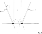
- FIG. 1 schematically a glass fiber 1 is shown, which has a surface to be spliced 2. Facing the surface 2 to be spliced, an optical component 3 is arranged.
- the glass fiber 1 and the optical component 3 are made of silica glass.
- an end cap splice is made on a PCF.
- the surface 2 to be spliced is arranged substantially parallel to the surface of the optical component 3 and spaced therefrom.
- a laser beam 4 is directed to the portion of the surface of the optical component 3 to be connected to the glass fiber 1 and has an angle of incidence ⁇ which is between 15 ° and 45 °.
- the laser beam 4 is a laser beam, shaped as a ring beam, of a CO 2 laser source (not shown ) which, for reasons of clarity, is shown only schematically by the dashed lines designated by 4.
- the radiation 4 in the embodiment has a conical shape, which is generated either by beam shaping by means of suitable optical components or by continuous deflection of the laser beam 4.
- the laser beam 4 irradiates an annular zone 5 whose diameter is greater than that of the glass fiber 1.
- the glass fiber 1 is not hit directly by the laser beam 4.
- the laser beam 4 is not focused on the surface of the optical component 3.
- the slightly divergent beam of the laser beam 4 impinges on the surface of the optical component 3 and irradiates there the annular zone 5, which has a corresponding width due to the defocusing.
- the surface of the optical component 3 is heated by the laser radiation 4 until the material softens.
- the heating of the fiber 1, however, is required to ensure a stable splice.
- the glass fiber 1 and the optical component 3 When the glass fiber 1 and the optical component 3 have reached the respectively desired temperature, they are brought into contact to make the splice connection (not shown).
Landscapes
- Physics & Mathematics (AREA)
- Engineering & Computer Science (AREA)
- Plasma & Fusion (AREA)
- General Physics & Mathematics (AREA)
- Optics & Photonics (AREA)
- Mechanical Coupling Of Light Guides (AREA)
- Lasers (AREA)
Description
- Die Erfindung betrifft ein Verfahren zum laserbasierten Spleißen einer Glasfaser auf eine optische Komponente, umfassend folgende Schritte:
- Anordnen beider zu spleißender Oberflächen im Wesentlichen parallel zueinander und mit einem vorgegebenen Abstand voneinander und
- Ausrichten eines Laserstrahls auf die optische Komponente.
- Spleißen als Fügeverfahren wird insbesondere bei Fasern und optischen Komponenten eingesetzt, welche für die Ausbreitung von optischen Leistungen im kW-Bereich (z.B. Faserlaser) eingesetzt werden.
- Als optische Komponenten kommen z.B. Kieselglas-Endkappen in Frage, welche zur Versiegelung und zum Schutz vor Umwelteinflüssen von photonischen Kristallfasern (PCFs), bei welchen die Lichtführung zum Teil durch Luftkanäle erfolgt, Anwendung finden. Die Endkappen bieten zusätzlich die Möglichkeit einer Funktionalisierung, wie z.B. einer AR-Beschichtung, oder des Versehens der Endkappe mit einer sphärischen oder asphärischen Oberfläche, und können gleichzeitig als Halte- oder Justageelement verwendet werden. Es besteht die Möglichkeit, dass die Endkappen einen größeren Durchmesser als die Faser aufweisen, wodurch der Einsatz herkömmlicher Spleißgeräte nicht möglich ist.
- Wenn Fügepartner mit unterschiedlichen Querschnitten, spezifischen Wellenleiterstrukturen und/oder verschiedenen Dotierungen, wie z.B. PCFs, mechanisch stabil und ohne Materialqualitätseinbußen verbunden werden, wird vorzugsweise ein CO2-Laser als Wärmequelle verwendet. Grund dafür ist, dass die Laserwellenlänge eines CO2-Lasers sehr gut von den Materialien der Fügepartner (in der Regel Kieselglas) absorbiert wird. Damit werden außerdem Verunreinigungen durch Prozessgase oder Ablagerung von Elektroden- oder Drahtmaterial, welche bei herkömmlichen Verfahren auftreten, ausgeschlossen. Auch ist ein schneller Wechsel zwischen unterschiedlich zu spleißenden Komponenten möglich, wenn die Verfahrensparameter bereits bekannt sind, ohne dass z. B. Elektroden oder Gasdüsen, die einem Verschleiß unterliegen, gewechselt werden müssen oder das Verfahren "eingefahren" werden muss.
- Ein solches Verfahren wird beispielsweise in der
EP 1 128 960 B1 beschrieben, wonach die Oberfläche einer optischen Komponente mit einem Laserstahl mit nahezu senkrechtem Einfallswinkel bestrahlt und dadurch erwärmt wird. - Es hat sich aber gezeigt, dass ein solches Verfahren zum Spleißen von Spezialfasern, wie z.B. PCFs, sowie Fasern aus unterschiedlichen Materialien wie z.B. Panda-Fasern und passive/aktive Single-Mode-Fasern geringer Führung, nicht geeignet ist, da oft viel zu hohe Temperaturen auftreten, welche die Materialstruktur der Spezialfaser zerstören oder negativ beeinflussen.
- Beim Spleißen von PCFs auf optische Komponenten ist es notwendig, dass die Luftkanäle sich bis zum Spleißpunkt erstrecken und nicht vorher zerstört werden, d.h. Kollabieren, um die optischen Eigenschaften zu erhalten.
- Bei Spezialfasern, die aus unterschiedlichen oder unterschiedlich dotierten Materialien bestehen, ist hingegen wichtig, dass während des Spleißverfahrens die Materialeigenschaften, die auf die unterschiedliche Zusammensetzung der Faser zurückzuführen sind, erhalten bleiben. Zu hohe Temperaturen beim Spleißen führen dazu, dass Diffusions- oder Ausgasvorgänge auftreten können, welche die optischen Eigenschaften der Faser negativ verändern.
- Der Erfindung liegt daher die Aufgabe zugrunde, ein gegenüber dem Stand der Technik verbessertes Verfahren anzugeben, bei welchem die Eigenschaften der Fügepartner beim Spleißen weitestgehend erhalten bleiben, welches eine hohe Reproduzierbarkeit aufweist und insbesondere zum Spleißen von Fügepartnern unterschiedlicher Querschnitte geeignet ist.
- Diese Aufgabe wird dadurch gelöst, dass der Einfallswinkel des Laserstrahls auf die Oberfläche der optischen Komponente zwischen 10° und 60°, vorzugsweise zwischen 15°und 45° beträgt.
- Der Einfallswinkel ist im Sinne der Erfindung der Winkel zwischen der Laserstrahlrichtung und der Oberflächennormalen der optischen Komponente.
- Der Begriff der Glasfaser erfasst im Sinne der Erfindung nicht nur eine einzelne optische Faser, sondern auch ein Faserbündel, dessen Einzelfasern gleichzeitig auf die optische Komponente gespleißt werden sollen.
- Durch die Erfindung wird erreicht, das nur ein Teil der Laserleistung auf die zu spleißende Oberfläche der Glasfaser wirkt, da nur ein Teil der Laserenergie, bedingt durch Fresnel-Reflexion, von der Oberfläche der optischen Komponente reflektiert und zur Oberfläche der Glasfaser gelangen kann. Durch geeignete Auswahl des Abstandes zwischen Oberfläche der optischen Komponente und der Glasfaser, des Einfallswinkels des Laserstrahls und/oder der Polarisation der Laserstrahlung können somit in einem einzigen Verfahrensschritt beide Oberflächen auf die für das Spleißen optimale Temperatur gebracht werden, ohne dass die Oberflächen einer unerwünschten und zu hohen thermischen Belastung ausgesetzt werden. Insbesondere können durch die Erfindung ausgewählte Bereiche der Glasfaser weitestgehend thermisch unbelastet bleiben, auch wenn der Abstand zwischen Glasfaser und optischer Komponente sehr klein ist. Beispielsweise kann nur das Material an der Oberfläche der optischen Komponente bis zur Erweichung erwärmt werden, während die Oberfläche der Glasfaser nur soweit hinreichend erwärmt wird, um eine stabile Spleißverbindung herzustellen, ohne dass es aber zu einer relevanten Erweichung des Materials der Glasfaser kommt. Die Struktur der Glasfaser wird in diesem Falle während des Spleißvorgangs zuverlässig erhalten.
- Auch ist es möglich, dass die Glasfaser während des Spleißens bereits die optische Komponente berührt, d.h., dass der Abstand zwischen den Fügepartnern null beträgt, und nicht, wie üblich, erst nach Erreichen der Spleißtemperatur mit dieser in Berührung gebracht wird.
- Eine bevorzugte Ausführungsform des Verfahrens sieht vor, dass der Laserstrahl mit einer CO2 Laserquelle erzeugt wird. Die hohe Absorption der CO2-Laserwellenlänge seitens der Fügepartner bewirkt ein hervorragendes Anschmelzen derselben. Außerdem kann durch geeignete Auswahl der Laserleistung die zu erreichende Temperatur der Fügepartner stufenlos und sehr genau gesteuert werden, was zu sehr guten und reproduzierbaren Ergebnissen führt.
- Weiter bevorzugt ist der Laserstrahl als Ringstrahl ausgebildet. Der Laserstrahl bestrahlt dabei eine ringförmige Zone auf der Oberfläche der optischen Komponente. Diese ringförmige Zone kann vollständig bestrahlt werden. Ebenso ist es möglich, dass nur Ringsegmente bestrahlt werden. Dies kann mittels geeigneter Optik durch Strahlformung erfolgen. Alternativ ist es möglich, den Laserstrahl kontinuierlich über die ringförmige Zone auf der Oberfläche der optischen Komponente zu führen. Damit wird nur ein ringförmiger Bereich an der Oberfläche der optischen Komponente aufgeheizt und auf die Oberfläche der Glasfaser reflektiert, wodurch der innere Bereich der Glasfaser, je nach eingestellter Laserleistung, Polarisation, Einfallswinkel des Laserstrahls und Abstand der Fügepartner, nur geringfügig thermisch belastet wird. Dies ist insbesondere bei PCFs, welche oft einen inneren Bereich mit Luftkanälen aufweisen, vorteilhaft, so dass einem Kollaps der inneren Struktur während des Spleißens entgegengewirkt werden kann.
- Insbesondere ist es möglich, dass die Form und/oder die Größe der ringförmigen Zone während des Spleißvorgangs variiert werden. Dies kann durch Änderung des Fokus der Laserstrahlung erfolgen (Variation der Ringbreite). Ebenso können Laseroptik und optische Komponente relativ zueinander bewegt werden. Ohne Änderung des Einfallswinkels ändert sich dabei der Durchmesser der ringförmigen Zone. Diese Variation dient der gezielten (zeitlichen) Temperaturführung an den Oberflächen der Fügepartner während des Spleißvorgangs.
- Bei einem bevorzugten Ausführungsbeispiel der Erfindung ist der Durchmesser der ringförmigen Zone größer als der Durchmesser der Glasfaser. Dadurch kann erreicht werden, dass die Oberfläche der optischen Komponente zum Zwecke der Erweichung stärker erhitzt wird, während die Glasfaser nur leicht erwärmt wird, um eine stabile Spleißverbindung herzustellen. Die Glasfaser wird nicht direkt von der Laserstrahlung getroffen, eine unerwünschte Beeinträchtigung der Glasfaser durch thermische Belastung wird vermieden.
- Der Laserstrahl wird bei einer noch weiter bevorzugten Ausführungsform nicht auf die Oberfläche der optischen Komponente fokussiert, so dass ein homogeneres und großflächigeres Anschmelzen der Oberfläche der optischen Komponente bewirkt werden kann. Außerdem wird somit ermöglicht, dass der Anteil der zur Oberfläche der Glasfaser reflektierten Laserstrahlung verringert wird. Es ist auf diese Weise möglich, durch geeignetes Einstellen der Laserleistung, Einfallswinkel und Fokussierung des Laserstrahls und Abstand zwischen den Fügepartnern, die thermische Belastung der Oberfläche der Glasfaser praktisch unabhängig von derjenigen der optischen Komponente zu steuern.
- Bei einer bevorzugten Ausgestaltung des erfindungsgemäßen Verfahrens wird die Leistung des Laserstrahls als Funktion der Zeit während des Spleißvorgangs variiert. Zum Beispiel wird die Laserleistung zunächst von einem Anfangswert bis zu einem Endwert kontinuierlich gesteigert. Dann werden die erwärmten bzw. angeschmolzenen Oberflächen der Fügepartner miteinander zur Herstellung der Spleißverbindung in Berührung gebracht wird. Nach der Herstellung der Verbindung kann die Leistung des Laserstrahls als Funktion der Zeit kontinuierlich reduziert werden. Das langsame "Anfahren" der Laserleistung kann für eine schonende Erwärmung der Fügepartner im Bereich der Spleißstelle genutzt werden. Ebenso bewirkt die stetige Reduzierung der Laserleistung, dass unerwünschte Materialspannungen und entsprechende mechanische Verformungen, die die Qualität der optischen Verbindung beeinträchtigen würden, im Bereich des fertigen Spleißes vermieden werden.
- Das erfindungsgemäße Verfahren eignet sich besonders zum Spleißen von Spezialfasern, wie z.B. PCFs, sowie Fasern aus unterschiedlichen Materialien oder mit unterschiedlich dotierten Bereichen, wie z.B. Panda-Fasern oder passiven/aktiven Single-Mode-Fasern geringer Führung. Das erfindungsgemäße Verfahren stellt sicher, dass die Materialstruktur der Spezialfasern während des Spleißens nicht zerstört oder negativ beeinflusst wird.
- Die Erfindung wird jetzt anhand eines bevorzugten Ausführungsbeispiels beschrieben. Es zeigt:
- Fig. 1
- eine schematische Seitenansicht zweier Fügepartner.
- In der
Figur 1 ist schematisch eine Glasfaser 1 gezeigt, welche eine zu spleißende Oberfläche 2 aufweist. Der zu spleißenden Oberfläche 2 zugewandt ist eine optische Komponente 3 angeordnet. Die Glasfaser 1 und die optische Komponente 3 sind aus Kieselglas hergestellt. In derFigur 1 wird z.B. ein Endkappenspleiß an einer PCF hergestellt. - Die zu spleißende Oberfläche 2 ist im Wesentlichen parallel zur Oberfläche der optischen Komponente 3 und von dieser beabstandet angeordnet.
- Ein Laserstrahl 4 ist auf den Abschnitt der Oberfläche der optischen Komponente 3, der mit der Glasfaser 1 verbunden werden soll, gerichtet und weist einen Einfallswinkel α, welcher zwischen 15° und 45° liegt, auf.
- Bei dem Laserstrahl 4 handelt es sich um einen als Ringstrahl geformten Laserstrahl einer nicht gezeigten CO2-Laserquelle, welcher aufgrund der Übersichtlichkeit nur schematisch durch die mit 4 bezeichneten gestrichelten Linien dargestellt ist. Die Strahlung 4 hat bei dem Ausführungsbeispiel eine Kegelmantelform, die entweder durch Strahlformung mittels geeigneter optischer Komponenten oder durch kontinuierliche Ablenkung des Laserstrahls 4 erzeugt wird. Der Laserstrahl 4 bestrahlt eine Ringzone 5, deren Durchmesser größer ist als derjenige der Glasfaser 1. Die Glasfaser 1 wird nicht direkt von dem Laserstrahl 4 getroffen.
- Wie in der
Figur 1 zu erkennen ist, ist der Laserstrahl 4 nicht auf die Oberfläche der optischen Komponente 3 fokussiert. Das leicht divergente Strahlenbündel des Laserstrahls 4 trifft auf die Oberfläche der optischen Komponente 3 auf und bestrahlt dort die Ringzone 5, die aufgrund der Defokussierung eine entsprechende Breite hat. - Die Oberfläche der optischen Komponente 3 wird durch die Laserstrahlung 4 bis zur Erweichung des Materials erhitzt.
- Ein Teil des Laserstrahls 4 wird, von der Fokussierung des Laserstrahls und vom Einfallswinkel α abhängig, von der Oberfläche der optischen Komponente 3 reflektiert und zur Oberfläche 2 der Glasfaser 1 gelenkt wo er eine Erwärmung der Glasfaser 1 bewirkt, ohne dass es zur Erweichung und damit zur Zerstörung der Struktur der Glasfaser 1 kommt. Die Erwärmung der Faser 1 ist allerdings zur Gewährleistung einer stabilen Spleißverbindung erforderlich.
- Wenn die Glasfaser 1 und die optische Komponente 3 die jeweils gewünschte Temperatur erreicht haben, werden diese in Berührung gebracht, um die Spleißverbindung herzustellen (nicht dargestellt).
Claims (12)
- Verfahren zum laserbasierten Spleißen einer Glasfaser (1) auf eine optische Komponente (3), umfassend folgende Schritte:- Anordnen beider zu spleißender Oberflächen im Wesentlichen parallel zueinander und mit einem vorgegebenen Abstand voneinander und- Ausrichten eines Laserstrahls (4) auf die optische Komponente (3), wobei der Einfallswinkel des Laserstrahls (4) auf die Oberfläche der optischen Komponente zwischen 10° und 60°, vorzugsweise zwischen 15° und 45° beträgt,dadurch gekennzeichnet, dass der Abstand zwischen den zu spleißenden Oberflächen und/oder der Einfallswinkel des Laserstrahls und/oder die Polarisation des Laserstrahls in der Weise aufeinander abgestimmt werden, dass der von der Oberfläche der optischen Komponente reflektierte Laserstrahl die zu spleißende Oberfläche der Glasfaser erwärmt, wobei der Laserstrahl eine ringförmige Zone auf der Oberfläche der optischen Komponente (3) ganz oder teilweise bestrahlt.
- Verfahren nach Anspruch 1, dadurch gekennzeichnet, dass der Laserstrahl (4) polarisiert ist.
- Verfahren nach einem der Ansprüche 1 bis 2, dadurch gekennzeichnet, dass der Laserstrahl mittels einer CO2-Laserquelle erzeugt wird.
- Verfahren nach einem der Ansprüche 1 bis 3, dadurch gekennzeichnet, dass die Breite und/oder der Durchmesser der ringförmigen Zone während des Spleißvorgangs variiert werden.
- Verfahren nach einem der Ansprüche 1 bis 4, dadurch gekennzeichnet, dass der Durchmesser der ringförmigen Zone größer ist als der Faserdurchmesser.
- Verfahren nach einem der vorgehenden Ansprüche, dadurch gekennzeichnet, dass der Laserstrahl nicht auf die Oberfläche der optischen Komponente fokussiert wird.
- Verfahren nach einem der Ansprüche 1 bis 6, dadurch gekennzeichnet, dass die Leistung des Laserstrahls als Funktion der Zeit während des Spleißvorgangs variiert wird.
- Verfahren nach einem der Ansprüche 1 bis 7, dadurch gekennzeichnet, dass die Glasfaser aus reinem oder dotiertem Kieselglas hergestellt ist.
- Verfahren nach einem der Ansprüche 1 bis 8, dadurch gekennzeichnet, dass die Glasfaser eine photonische Kristallfaser ist.
- Verfahren nach einem der Ansprüche 1 bis 9, dadurch gekennzeichnet, dass die Glasfaser, im Faserquerschnitt gesehen, Bereiche mit unterschiedlicher Dotierung aufweist.
- Verwendung des Verfahrens nach einem der Ansprüche 1 bis 10 zur Konfektionierung einer Glasfaser mit einem Faserstecker.
- Verwendung des Verfahrens nach einem der Ansprüche 1 bis 11 zum Spleißen einer Glasfaser auf eine optische Komponente eines Faserlasers.
Applications Claiming Priority (2)
| Application Number | Priority Date | Filing Date | Title |
|---|---|---|---|
| DE102011119713.7A DE102011119713B9 (de) | 2011-11-30 | 2011-11-30 | Laserbasiertes Spleißen von Glasfasern auf optische Komponenten |
| PCT/EP2012/004875 WO2013079184A1 (de) | 2011-11-30 | 2012-11-26 | Laserbasiertes spleissen von glasfasern auf optische komponenten |
Publications (2)
| Publication Number | Publication Date |
|---|---|
| EP2786187A1 EP2786187A1 (de) | 2014-10-08 |
| EP2786187B1 true EP2786187B1 (de) | 2018-02-28 |
Family
ID=47429727
Family Applications (1)
| Application Number | Title | Priority Date | Filing Date |
|---|---|---|---|
| EP12805939.1A Active EP2786187B1 (de) | 2011-11-30 | 2012-11-26 | Laserbasiertes spleissen von glasfasern auf optische komponenten |
Country Status (7)
| Country | Link |
|---|---|
| US (2) | US20140298864A1 (de) |
| EP (1) | EP2786187B1 (de) |
| JP (1) | JP5901786B2 (de) |
| DE (1) | DE102011119713B9 (de) |
| DK (1) | DK2786187T3 (de) |
| NO (1) | NO2855827T3 (de) |
| WO (1) | WO2013079184A1 (de) |
Family Cites Families (20)
| Publication number | Priority date | Publication date | Assignee | Title |
|---|---|---|---|---|
| JPS5186231A (de) * | 1975-01-28 | 1976-07-28 | Hiromitsu Naka | |
| US3960531A (en) * | 1975-07-28 | 1976-06-01 | Corning Glass Works | Method and apparatus for splicing optical fibers |
| JPS55151611A (en) * | 1979-05-16 | 1980-11-26 | Nippon Telegr & Teleph Corp <Ntt> | Optical fiber splicer |
| JPS55155314A (en) * | 1979-05-21 | 1980-12-03 | Nippon Telegr & Teleph Corp <Ntt> | Connecting method of optical fiber and its connector |
| US4727237A (en) * | 1987-05-04 | 1988-02-23 | Hewlett-Packard Company | Pyrolysis coated optical fiber splices: apparatus and method |
| US5161207A (en) * | 1991-03-18 | 1992-11-03 | Hughes Aircraft Company | Optical fiber circumferentialy symmetric fusion splicing and progressive fire polishing |
| US5299274A (en) * | 1992-06-25 | 1994-03-29 | Hughes Aircraft Company | Optical fiber laser fusion splicer |
| US5835210A (en) * | 1997-09-10 | 1998-11-10 | Cymber, Inc. | Multi-pass spectrometer |
| US6033515A (en) * | 1998-07-17 | 2000-03-07 | Lightpath Technologies, Inc. | Use of a laser to fusion-splice optical components of substantially different cross-sectional areas |
| US6360039B1 (en) * | 1998-07-17 | 2002-03-19 | Lightpath Technologies, Inc. | Fabrication of collimators employing optical fibers fusion-spliced to optical elements of substantially larger cross-sectional areas |
| US6217698B1 (en) * | 1998-07-17 | 2001-04-17 | Lightpath Technologies, Inc. | Use of a laser to fusion-splice optical components of substantially different cross-sectional areas |
| US6362455B1 (en) * | 2000-03-07 | 2002-03-26 | Corning Incorporated | Spinning mirror laser system with focused beam |
| US7298944B2 (en) * | 2000-11-28 | 2007-11-20 | Fujikura Ltd. | Method and device for manufacturing optical fiber grating, optical fiber grating, optical module, and optical communication system |
| DE10127331B4 (de) * | 2001-05-22 | 2006-06-14 | Schott Ag | Verfahren zum Verbinden mindestens einer optischen Faser mit einer GRIN-Linse und Filtermodul |
| EP1367417A1 (de) * | 2002-05-23 | 2003-12-03 | Corning Incorporated | Justiertechnik für optische Faser |
| US7029187B2 (en) * | 2002-05-31 | 2006-04-18 | Corning Incorporated | Optical fiber splice manufacturing process |
| US20050180695A1 (en) * | 2002-10-15 | 2005-08-18 | Sagitta Engineering Solutions Ltd. | Method and apparatus for planar lightwave circuits pigtailing |
| JP2004264843A (ja) * | 2003-02-14 | 2004-09-24 | Fujikura Ltd | 光機能素子付き光ファイバ、光機能素子付き光ファイバの製造方法及び光機能素子付き光ファイバの製造装置 |
| US7306376B2 (en) * | 2006-01-23 | 2007-12-11 | Electro-Optics Technology, Inc. | Monolithic mode stripping fiber ferrule/collimator and method of making same |
| KR100906287B1 (ko) * | 2007-08-22 | 2009-07-06 | 광주과학기술원 | 측면 조영이 가능한 광섬유 프로브 및 광섬유 프로브 제조방법 |
-
2011
- 2011-11-30 DE DE102011119713.7A patent/DE102011119713B9/de not_active Expired - Fee Related
-
2012
- 2012-11-26 US US14/361,769 patent/US20140298864A1/en not_active Abandoned
- 2012-11-26 DK DK12805939.1T patent/DK2786187T3/en active
- 2012-11-26 WO PCT/EP2012/004875 patent/WO2013079184A1/de not_active Ceased
- 2012-11-26 EP EP12805939.1A patent/EP2786187B1/de active Active
- 2012-11-26 JP JP2014543793A patent/JP5901786B2/ja not_active Expired - Fee Related
-
2013
- 2013-05-08 NO NO13723648A patent/NO2855827T3/no unknown
-
2021
- 2021-07-01 US US17/365,485 patent/US11982840B2/en active Active
Also Published As
| Publication number | Publication date |
|---|---|
| US11982840B2 (en) | 2024-05-14 |
| DE102011119713B9 (de) | 2018-10-11 |
| DE102011119713B4 (de) | 2018-07-05 |
| EP2786187A1 (de) | 2014-10-08 |
| US20220003930A1 (en) | 2022-01-06 |
| DE102011119713A1 (de) | 2013-06-06 |
| NO2855827T3 (de) | 2018-05-12 |
| US20140298864A1 (en) | 2014-10-09 |
| DK2786187T3 (en) | 2018-06-06 |
| JP5901786B2 (ja) | 2016-04-13 |
| WO2013079184A1 (de) | 2013-06-06 |
| JP2015505981A (ja) | 2015-02-26 |
Similar Documents
| Publication | Publication Date | Title |
|---|---|---|
| DE69621974T2 (de) | Dispersionsgesteuerter optischer Wellenleiter | |
| EP2556397B1 (de) | Verfahren und anordnung zum erzeugen eines laserstrahls mit unterschiedlicher strahlprofilcharakteristik mittels einer mehrfachclad-faser | |
| DE60011995T2 (de) | Herstellung von kollimatoren mit optischen fasern, angespleisst an optische elemente mit grösserem querschnitt | |
| DE69008915T2 (de) | Verfahren und Vorrichtung zur Fabrikation von Mikrolinsen an optischen Fasern. | |
| DE3685911T2 (de) | Herstellungsverfahren einer passiven faseroptischen komponente. | |
| DE68903528T2 (de) | Verbinden von optischen wellenleitern. | |
| DE60313491T2 (de) | Linse auf optischer faser oder auf wellenleiter | |
| DE69029175T2 (de) | Methode zur Herstellung eines Lichtwellenleiter-Kopplers | |
| WO2018219710A1 (de) | VERFAHREN ZUM TIEFSCHWEIßEN EINES WERKSTÜCKS, MIT VERTEILUNG DER LASERLEISTUNG AUF MEHRERE FOKI | |
| WO2020165142A1 (de) | Verfahren zum fügen von kupfer-hairpins und stator | |
| DE102008063829A1 (de) | Verfahren zur Herstellung eines zylinderförmigen optischen Bauteils aus Quarzglas sowie nach dem Verfahren erhaltenes optisch aktives Bauteil | |
| DE102009009367B4 (de) | Lichtleiter zur Übertragung von Strahlung sowie Herstellverfahren | |
| EP3814139A1 (de) | Vorrichtung und verfahren zum trennen einer verbundsicherheitsglastafel | |
| DE68924807T2 (de) | Verfahren zur reproduzierbaren Herstellung von optischen Kopplern. | |
| DE102011119713B9 (de) | Laserbasiertes Spleißen von Glasfasern auf optische Komponenten | |
| EP1906220A2 (de) | Verfahren zum Strukturieren von lichtleitenden Fasern entlang deren Längsachse (longitudinale Strukturierung) basierend auf der nicht-linearen Absorption von Laserstrahlung | |
| DE102019128251A1 (de) | Verfahren zum Fügen von zwei Fügepartnern mittels ultrakurzer Laserpulse | |
| DE19534106A1 (de) | Optische Faser und Herstellungsverfahren dafür | |
| EP4626634A1 (de) | Verfahren und lasersystem zum trennen eines werkstücks | |
| DE102022110078A1 (de) | Vorrichtung und Verfahren zur Modifikation des Strahlprofils eines Laserstrahls | |
| WO2012143070A1 (de) | Verfahren zum herstellen eines lichtwellenleiters in einem polymer | |
| DE2358881C2 (de) | Verfahren zur Herstellung einer Ankopplungsoptik an einem Lichtwellenleiter | |
| DE10128827A1 (de) | Justierverfahren, insbesondere Laser-Justierverfahren und hierfür geeigneter Aktor | |
| DE102019116812A1 (de) | Bearbeitungsvorrichtung für Glasfasern | |
| WO2022238215A1 (de) | Vorrichtung und verfahren zur bestimmung der strahlgüte |
Legal Events
| Date | Code | Title | Description |
|---|---|---|---|
| PUAI | Public reference made under article 153(3) epc to a published international application that has entered the european phase |
Free format text: ORIGINAL CODE: 0009012 |
|
| 17P | Request for examination filed |
Effective date: 20140630 |
|
| AK | Designated contracting states |
Kind code of ref document: A1 Designated state(s): AL AT BE BG CH CY CZ DE DK EE ES FI FR GB GR HR HU IE IS IT LI LT LU LV MC MK MT NL NO PL PT RO RS SE SI SK SM TR |
|
| DAX | Request for extension of the european patent (deleted) | ||
| GRAP | Despatch of communication of intention to grant a patent |
Free format text: ORIGINAL CODE: EPIDOSNIGR1 |
|
| INTG | Intention to grant announced |
Effective date: 20170818 |
|
| GRAS | Grant fee paid |
Free format text: ORIGINAL CODE: EPIDOSNIGR3 |
|
| GRAA | (expected) grant |
Free format text: ORIGINAL CODE: 0009210 |
|
| AK | Designated contracting states |
Kind code of ref document: B1 Designated state(s): AL AT BE BG CH CY CZ DE DK EE ES FI FR GB GR HR HU IE IS IT LI LT LU LV MC MK MT NL NO PL PT RO RS SE SI SK SM TR |
|
| RAP1 | Party data changed (applicant data changed or rights of an application transferred) |
Owner name: FRAUNHOFER-GESELLSCHAFT ZUR FOERDERUNG DER ANGEWAN |
|
| REG | Reference to a national code |
Ref country code: GB Ref legal event code: FG4D Free format text: NOT ENGLISH Ref country code: CH Ref legal event code: EP |
|
| REG | Reference to a national code |
Ref country code: AT Ref legal event code: REF Ref document number: 974755 Country of ref document: AT Kind code of ref document: T Effective date: 20180315 |
|
| REG | Reference to a national code |
Ref country code: IE Ref legal event code: FG4D Free format text: LANGUAGE OF EP DOCUMENT: GERMAN |
|
| REG | Reference to a national code |
Ref country code: DE Ref legal event code: R096 Ref document number: 502012012272 Country of ref document: DE |
|
| REG | Reference to a national code |
Ref country code: DK Ref legal event code: T3 Effective date: 20180531 |
|
| REG | Reference to a national code |
Ref country code: SE Ref legal event code: TRGR |
|
| REG | Reference to a national code |
Ref country code: NL Ref legal event code: MP Effective date: 20180228 |
|
| REG | Reference to a national code |
Ref country code: LT Ref legal event code: MG4D |
|
| PG25 | Lapsed in a contracting state [announced via postgrant information from national office to epo] |
Ref country code: ES Free format text: LAPSE BECAUSE OF FAILURE TO SUBMIT A TRANSLATION OF THE DESCRIPTION OR TO PAY THE FEE WITHIN THE PRESCRIBED TIME-LIMIT Effective date: 20180228 Ref country code: FI Free format text: LAPSE BECAUSE OF FAILURE TO SUBMIT A TRANSLATION OF THE DESCRIPTION OR TO PAY THE FEE WITHIN THE PRESCRIBED TIME-LIMIT Effective date: 20180228 Ref country code: LT Free format text: LAPSE BECAUSE OF FAILURE TO SUBMIT A TRANSLATION OF THE DESCRIPTION OR TO PAY THE FEE WITHIN THE PRESCRIBED TIME-LIMIT Effective date: 20180228 Ref country code: CY Free format text: LAPSE BECAUSE OF FAILURE TO SUBMIT A TRANSLATION OF THE DESCRIPTION OR TO PAY THE FEE WITHIN THE PRESCRIBED TIME-LIMIT Effective date: 20180228 Ref country code: HR Free format text: LAPSE BECAUSE OF FAILURE TO SUBMIT A TRANSLATION OF THE DESCRIPTION OR TO PAY THE FEE WITHIN THE PRESCRIBED TIME-LIMIT Effective date: 20180228 Ref country code: NL Free format text: LAPSE BECAUSE OF FAILURE TO SUBMIT A TRANSLATION OF THE DESCRIPTION OR TO PAY THE FEE WITHIN THE PRESCRIBED TIME-LIMIT Effective date: 20180228 |
|
| REG | Reference to a national code |
Ref country code: NO Ref legal event code: T2 Effective date: 20180228 |
|
| PG25 | Lapsed in a contracting state [announced via postgrant information from national office to epo] |
Ref country code: BG Free format text: LAPSE BECAUSE OF FAILURE TO SUBMIT A TRANSLATION OF THE DESCRIPTION OR TO PAY THE FEE WITHIN THE PRESCRIBED TIME-LIMIT Effective date: 20180528 Ref country code: GR Free format text: LAPSE BECAUSE OF FAILURE TO SUBMIT A TRANSLATION OF THE DESCRIPTION OR TO PAY THE FEE WITHIN THE PRESCRIBED TIME-LIMIT Effective date: 20180529 Ref country code: LV Free format text: LAPSE BECAUSE OF FAILURE TO SUBMIT A TRANSLATION OF THE DESCRIPTION OR TO PAY THE FEE WITHIN THE PRESCRIBED TIME-LIMIT Effective date: 20180228 Ref country code: RS Free format text: LAPSE BECAUSE OF FAILURE TO SUBMIT A TRANSLATION OF THE DESCRIPTION OR TO PAY THE FEE WITHIN THE PRESCRIBED TIME-LIMIT Effective date: 20180228 |
|
| PG25 | Lapsed in a contracting state [announced via postgrant information from national office to epo] |
Ref country code: MT Free format text: LAPSE BECAUSE OF FAILURE TO SUBMIT A TRANSLATION OF THE DESCRIPTION OR TO PAY THE FEE WITHIN THE PRESCRIBED TIME-LIMIT Effective date: 20180228 |
|
| PG25 | Lapsed in a contracting state [announced via postgrant information from national office to epo] |
Ref country code: RO Free format text: LAPSE BECAUSE OF FAILURE TO SUBMIT A TRANSLATION OF THE DESCRIPTION OR TO PAY THE FEE WITHIN THE PRESCRIBED TIME-LIMIT Effective date: 20180228 Ref country code: EE Free format text: LAPSE BECAUSE OF FAILURE TO SUBMIT A TRANSLATION OF THE DESCRIPTION OR TO PAY THE FEE WITHIN THE PRESCRIBED TIME-LIMIT Effective date: 20180228 Ref country code: IT Free format text: LAPSE BECAUSE OF FAILURE TO SUBMIT A TRANSLATION OF THE DESCRIPTION OR TO PAY THE FEE WITHIN THE PRESCRIBED TIME-LIMIT Effective date: 20180228 Ref country code: AL Free format text: LAPSE BECAUSE OF FAILURE TO SUBMIT A TRANSLATION OF THE DESCRIPTION OR TO PAY THE FEE WITHIN THE PRESCRIBED TIME-LIMIT Effective date: 20180228 Ref country code: PL Free format text: LAPSE BECAUSE OF FAILURE TO SUBMIT A TRANSLATION OF THE DESCRIPTION OR TO PAY THE FEE WITHIN THE PRESCRIBED TIME-LIMIT Effective date: 20180228 |
|
| REG | Reference to a national code |
Ref country code: DE Ref legal event code: R097 Ref document number: 502012012272 Country of ref document: DE |
|
| PG25 | Lapsed in a contracting state [announced via postgrant information from national office to epo] |
Ref country code: SK Free format text: LAPSE BECAUSE OF FAILURE TO SUBMIT A TRANSLATION OF THE DESCRIPTION OR TO PAY THE FEE WITHIN THE PRESCRIBED TIME-LIMIT Effective date: 20180228 Ref country code: CZ Free format text: LAPSE BECAUSE OF FAILURE TO SUBMIT A TRANSLATION OF THE DESCRIPTION OR TO PAY THE FEE WITHIN THE PRESCRIBED TIME-LIMIT Effective date: 20180228 Ref country code: SM Free format text: LAPSE BECAUSE OF FAILURE TO SUBMIT A TRANSLATION OF THE DESCRIPTION OR TO PAY THE FEE WITHIN THE PRESCRIBED TIME-LIMIT Effective date: 20180228 |
|
| PLBE | No opposition filed within time limit |
Free format text: ORIGINAL CODE: 0009261 |
|
| STAA | Information on the status of an ep patent application or granted ep patent |
Free format text: STATUS: NO OPPOSITION FILED WITHIN TIME LIMIT |
|
| 26N | No opposition filed |
Effective date: 20181129 |
|
| PG25 | Lapsed in a contracting state [announced via postgrant information from national office to epo] |
Ref country code: SI Free format text: LAPSE BECAUSE OF FAILURE TO SUBMIT A TRANSLATION OF THE DESCRIPTION OR TO PAY THE FEE WITHIN THE PRESCRIBED TIME-LIMIT Effective date: 20180228 |
|
| REG | Reference to a national code |
Ref country code: CH Ref legal event code: PL |
|
| PG25 | Lapsed in a contracting state [announced via postgrant information from national office to epo] |
Ref country code: LU Free format text: LAPSE BECAUSE OF NON-PAYMENT OF DUE FEES Effective date: 20181126 Ref country code: MC Free format text: LAPSE BECAUSE OF FAILURE TO SUBMIT A TRANSLATION OF THE DESCRIPTION OR TO PAY THE FEE WITHIN THE PRESCRIBED TIME-LIMIT Effective date: 20180228 |
|
| REG | Reference to a national code |
Ref country code: BE Ref legal event code: MM Effective date: 20181130 |
|
| REG | Reference to a national code |
Ref country code: IE Ref legal event code: MM4A |
|
| PG25 | Lapsed in a contracting state [announced via postgrant information from national office to epo] |
Ref country code: CH Free format text: LAPSE BECAUSE OF NON-PAYMENT OF DUE FEES Effective date: 20181130 Ref country code: LI Free format text: LAPSE BECAUSE OF NON-PAYMENT OF DUE FEES Effective date: 20181130 |
|
| PG25 | Lapsed in a contracting state [announced via postgrant information from national office to epo] |
Ref country code: FR Free format text: LAPSE BECAUSE OF NON-PAYMENT OF DUE FEES Effective date: 20181130 Ref country code: IE Free format text: LAPSE BECAUSE OF NON-PAYMENT OF DUE FEES Effective date: 20181126 |
|
| PG25 | Lapsed in a contracting state [announced via postgrant information from national office to epo] |
Ref country code: BE Free format text: LAPSE BECAUSE OF NON-PAYMENT OF DUE FEES Effective date: 20181130 |
|
| REG | Reference to a national code |
Ref country code: AT Ref legal event code: MM01 Ref document number: 974755 Country of ref document: AT Kind code of ref document: T Effective date: 20181126 |
|
| PG25 | Lapsed in a contracting state [announced via postgrant information from national office to epo] |
Ref country code: AT Free format text: LAPSE BECAUSE OF NON-PAYMENT OF DUE FEES Effective date: 20181126 |
|
| PG25 | Lapsed in a contracting state [announced via postgrant information from national office to epo] |
Ref country code: TR Free format text: LAPSE BECAUSE OF FAILURE TO SUBMIT A TRANSLATION OF THE DESCRIPTION OR TO PAY THE FEE WITHIN THE PRESCRIBED TIME-LIMIT Effective date: 20180228 |
|
| PG25 | Lapsed in a contracting state [announced via postgrant information from national office to epo] |
Ref country code: PT Free format text: LAPSE BECAUSE OF FAILURE TO SUBMIT A TRANSLATION OF THE DESCRIPTION OR TO PAY THE FEE WITHIN THE PRESCRIBED TIME-LIMIT Effective date: 20180228 |
|
| PG25 | Lapsed in a contracting state [announced via postgrant information from national office to epo] |
Ref country code: MK Free format text: LAPSE BECAUSE OF NON-PAYMENT OF DUE FEES Effective date: 20180228 Ref country code: HU Free format text: LAPSE BECAUSE OF FAILURE TO SUBMIT A TRANSLATION OF THE DESCRIPTION OR TO PAY THE FEE WITHIN THE PRESCRIBED TIME-LIMIT; INVALID AB INITIO Effective date: 20121126 |
|
| PG25 | Lapsed in a contracting state [announced via postgrant information from national office to epo] |
Ref country code: IS Free format text: LAPSE BECAUSE OF FAILURE TO SUBMIT A TRANSLATION OF THE DESCRIPTION OR TO PAY THE FEE WITHIN THE PRESCRIBED TIME-LIMIT Effective date: 20180628 |
|
| P01 | Opt-out of the competence of the unified patent court (upc) registered |
Effective date: 20230524 |
|
| PGFP | Annual fee paid to national office [announced via postgrant information from national office to epo] |
Ref country code: DE Payment date: 20251118 Year of fee payment: 14 |
|
| PGFP | Annual fee paid to national office [announced via postgrant information from national office to epo] |
Ref country code: GB Payment date: 20251120 Year of fee payment: 14 |
|
| PGFP | Annual fee paid to national office [announced via postgrant information from national office to epo] |
Ref country code: NO Payment date: 20251118 Year of fee payment: 14 |
|
| PGFP | Annual fee paid to national office [announced via postgrant information from national office to epo] |
Ref country code: DK Payment date: 20251119 Year of fee payment: 14 |
|
| PGFP | Annual fee paid to national office [announced via postgrant information from national office to epo] |
Ref country code: SE Payment date: 20251119 Year of fee payment: 14 |