EP2785044A2 - Camera module - Google Patents
Camera module Download PDFInfo
- Publication number
- EP2785044A2 EP2785044A2 EP13275303.9A EP13275303A EP2785044A2 EP 2785044 A2 EP2785044 A2 EP 2785044A2 EP 13275303 A EP13275303 A EP 13275303A EP 2785044 A2 EP2785044 A2 EP 2785044A2
- Authority
- EP
- European Patent Office
- Prior art keywords
- case
- camera module
- coupling
- lens barrel
- housing
- Prior art date
- Legal status (The legal status is an assumption and is not a legal conclusion. Google has not performed a legal analysis and makes no representation as to the accuracy of the status listed.)
- Granted
Links
Images


Classifications
-
- G—PHYSICS
- G03—PHOTOGRAPHY; CINEMATOGRAPHY; ANALOGOUS TECHNIQUES USING WAVES OTHER THAN OPTICAL WAVES; ELECTROGRAPHY; HOLOGRAPHY
- G03B—APPARATUS OR ARRANGEMENTS FOR TAKING PHOTOGRAPHS OR FOR PROJECTING OR VIEWING THEM; APPARATUS OR ARRANGEMENTS EMPLOYING ANALOGOUS TECHNIQUES USING WAVES OTHER THAN OPTICAL WAVES; ACCESSORIES THEREFOR
- G03B17/00—Details of cameras or camera bodies; Accessories therefor
- G03B17/02—Bodies
-
- H—ELECTRICITY
- H04—ELECTRIC COMMUNICATION TECHNIQUE
- H04N—PICTORIAL COMMUNICATION, e.g. TELEVISION
- H04N23/00—Cameras or camera modules comprising electronic image sensors; Control thereof
- H04N23/50—Constructional details
- H04N23/51—Housings
-
- H—ELECTRICITY
- H04—ELECTRIC COMMUNICATION TECHNIQUE
- H04N—PICTORIAL COMMUNICATION, e.g. TELEVISION
- H04N23/00—Cameras or camera modules comprising electronic image sensors; Control thereof
- H04N23/50—Constructional details
- H04N23/55—Optical parts specially adapted for electronic image sensors; Mounting thereof
Definitions
- the present technology generally relates to a camera module.
- portable communication terminals such as mobile phones, personal digital assistants (PDAs), portable computers, or the like to transmit image data in addition to text or voice data.
- PDAs personal digital assistants
- portable computers or the like to transmit image data in addition to text or voice data.
- Portable communications terminals are commonly provided with a camera module to transmit image data, facilitate video chatting, and the like.
- Some of embodiments herein provide a camera module with: a stopper member for limiting movement of a lens barrel to be formed integrally with a case thereof, and a coupling structure for coupling with an external device to be formed integrally with the case thereof. These, for example, improve a degree of design freedom for coupling to various external devices, implementing miniaturization and slimness and simplifying the manufacturing process.
- a camera module may include a lens barrel; a housing having the lens barrel disposed therein; and a case coupled to the housing to cover outer surfaces of the housing, wherein the case includes a protrusion part protruding inwardly from an upper edge of the case and formed integrally with the case.
- the lens barrel may include at least one or more lenses disposed in an optical axis direction.
- the protrusion part of the case may be configured to limit movement of the lens barrel in the optical axis direction.
- a lower surface of the protrusion part may partially contact an upper surface of the housing.
- the lens barrel may include a catching part protruding from an outer surface thereof and facing the protrusion part.
- the case may further include a coupling forming part protruding outwardly from the upper edge of the case.
- the coupling forming part may be formed integrally with the case.
- an upper portion of the case provided with the coupling forming part may have a cross-sectional area greater than that of a lower portion of the case.
- a cross-sectional area of the coupling forming part in the horizontal direction may be decreased upwardly in the optical axis direction.
- the coupling forming part may be provided with a coupling part for coupling with an external device.
- the coupling part may define a groove recessed upwardly in the optical axis direction from a lower surface of the coupling forming part.
- the coupling part may have a shape of a hole penetrating through the coupling forming part.
- the camera module may further include a cover part coupled to the case to cover an upper portion of the coupling forming part.
- the cover part may be coupled to the coupling forming part via an adhesive.
- the coupling forming part may define an insertion groove formed in an outer edge of the upper portion thereof, and the cover part may have an insertion protrusion protruding from an outer edge thereof, the insertion protrusion being inserted into the insertion groove.
- the camera module may further include a transparent window part coupled to an upper surface of the case.
- the transparent window part may be coupled to the case via an adhesive.
- the upper surface of the case may be provided with a step part stepped downwardly in the optical axis direction, and the transparent window part may be mounted on the step part.
- a camera module may include a lens barrel; a housing having the lens barrel disposed therein; and a case coupled to the housing to cover outer surfaces of the housing.
- the case may be provided with a coupling part for coupling with an external device, the coupling part protruding from an outer surface of the case, and an inner surface of the case corresponding to a portion thereof on which the coupling part is formed may be a flat surface.
- the lens barrel may include at least one or more lenses disposed in an optical axis direction.
- the coupling part may be formed integrally with the case.
- the coupling part may have a polyhedral shape.
- the case may include a protrusion part protruding inwardly from an upper edge of the case.
- the lens barrel may include a catching part protruding from an outer surface thereof and facing the protrusion part.
- a camera module may comprise a lens barrel, a housing receiving the lens barrel therein, and a case covering the housing, the case having a first part protruding inwardly from an upper edge of the case and a second part protruding outwardly from the upper edge of the case.
- the first and second parts of the case may be formed integrally as one piece with the case.
- the first part of the case may be configured to limit movement of the lens barrel in an optical axis direction.
- the second part of the case may be configured to couple with an external device.
- the camera module may further comprise a transparent window part coupled to the case.
- the upper surface of the case may comprise a step part to mount the transparent window part thereon.
- the lens barrel may comprise a catching part protruding from an outer surface thereof and facing the protrusion part.
- a lower surface of the first part may contact an upper surface of the housing.
- the second part of the case may comprise a groove or a hole.
- the case may further comprise a cover part covering an upper portion of the second part of the case.
- the cover part may be coupled to the second part of the case via an adhesive.
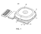
- FIG. 1 is an assembled, perspective view of a camera module according to an embodiment of the present invention.
- FIG. 2 is an exploded perspective view of the camera module according to the embodiment of the present invention.
- a camera module 100 may include a case 10, a housing 40, a lens barrel 20, an infrared filter 50, an image sensor 61, a printed circuit board 60, a cover part 70, and a transparent window part or window glass part 80.
- An optical axis direction refers to a vertical direction based on the lens barrel 20, and a horizontal direction refers to a direction perpendicular to the optical axis direction.
- the lens barrel 20 may have, for example, a hollow cylindrical shape such that at least one or more lenses for imaging an object may be received therein, and the lens may be provided in the lens barrel 20 in the optical axis direction.
- the lens barrel 20 may be coupled to the housing 40.
- the lens barrel 20 may be disposed in the housing 40.
- the lens barrel 20 may move in the optical axis direction in order to perform auto-focusing.
- an actuator 30 including a voice coil motor (VCM) may be provided.
- the actuator 30 may include a coil 33, a magnet 31, a position sensor 35, and a yoke (not shown).
- the magnet 31 may be mounted on one surface of the lens barrel 20, and the coil 33 may be mounted in the housing 40 to face the magnet 31.
- the coil 33 may allow the lens barrel 20 to move in the optical axis direction by electromagnetic interaction between the coil 33 and the magnet 31 adjacent to each other.
- the magnet 31 may form a predetermined magnetic field, such that when power is applied to the coil 33, a driving force caused by the electromagnetic force between the magnet 31 and the coil 33 may be generated, such that the lens barrel 20 may move in the optical axis direction by the driving force.
- the element for moving the lens barrel 20 is not limited to the actuator 30 including the VCM.
- Various devices such as a mechanical driving device, a piezoelectric driving device using a piezoelectric element, and the like, may be used.
- the lens barrel 20 may move through the operation as described above to perform an auto-focusing function or a zoom function.
- the position sensor 35 may be provided in the center of the coil 33.
- the position sensor 35 may sense a current position of the lens barrel 20 to provide current position information of the lens barrel 20 to a control part (not shown).
- the control part (not shown) may control movements of the lens barrel 20 by using the current position information of the lens barrel 20 received from the position sensor 35 and position information regarding a destination to which the lens barrel 20 needs to move.
- the housing 40 may not be required to have a space for disposing the position sensor 35. From this, the actuator 30 may be miniaturized, and a manufacturing tolerance may be decreased during a manufacturing process.
- the case 10 may be coupled to the housing 40 in order to enclose or cover outer surfaces of the housing 40.
- a conductive coating material (not shown) may be applied to at least one of the inner surfaces of the case 10 and the outer surfaces of the housing 40.
- An electromagnetic wave generated at the time of driving the camera module may be shielded by the conductive coating material (not shown).
- an electromagnetic wave may be generated at the time of driving the camera module.
- the electromagnetic wave as described above is emitted to the exterior of the camera module, the electromagnetic wave may affect electronic components, thereby causing a communications error or malfunctioning.
- a conductive coating material (not shown) may be applied to at least one of the inner surfaces of the case 10 and the outer surfaces of the housing 40.
- an electromagnetic wave generated by an external device on the image sensor 61 may be blocked, and various types of noise may also be blocked.
- conductive epoxy may be used, but the present invention is not limited thereto.
- Various materials having conductivity may be used.
- a conductive film or conductive tape may be attached to at least one of the inner surfaces of the case 10 and the outer surfaces of the housing 40.
- the case 10 and the housing 40 may be injection-molded.
- the case 10 and the housing 40 may be plastic injection-molded products.
- the case 10 may include a protrusion part 11 protruding inwardly from an upper edge of the case 10 and a coupling forming part 13 protruding outwardly from the upper edge of the case 10.
- a lower portion of the case 10 may have a rectangular parallelepiped shape.
- An upper portion of the case 10 may protrude outwardly in the horizontal direction further than the lower portion of the case.
- the upper portion of the case 10 provided with the coupling forming part 13 may have a cross-sectional area greater than that of the lower portion of the case 10, in the horizontal direction.
- a cross-sectional area of the coupling forming part 13 in the horizontal direction may be decreased upwardly in the optical axis direction.
- the shape of the case 10 is not limited to the above-mentioned shape, but may be variously changed according to shapes of the housing 40 and an external device in which the camera module is mounted.
- a through-hole 11a may be formed in an upper surface of the case 10 such that external light may be incident therethrough.
- the external light incident through the through-hole 11a may be received in the image sensor 61 via the lens.
- the transparent window part or window glass part 80 may be mounted on the upper surface of the case 10 such that the window glass part 80 covers the through-hole 11a in order to protect the lens.
- the upper surface of the case 10 may be formed in a stepped manner.
- the upper surface of the case 10 may be provided with a step part 17 stepped downwardly in the optical axis direction, and the window glass part 80 may be mounted on the step part 17.
- Protective tape 90 may be selectively attached to an upper surface of the transparent window part or window glass part 80.
- cover part 70 may be coupled to the coupling forming part 13 of the case 10 so as to cover an upper portion of the coupling forming part 13.
- the coupling forming part 13 may have at least one insertion groove 19 formed in an outer edge of the upper portion thereof, and the cover part 70 may have at least one insertion protrusion 71 protruding from an outer edge thereof.
- the insertion protrusion 71 of the cover part 70 may be inserted into the insertion groove 19 of the coupling forming part 13, such that the cover part 70 may be coupled to the coupling forming part 13.
- cover part 70 may be fixed to the coupling forming part 13 via an adhesive 75.
- a predetermined space may be formed between the cover part 70 and the coupling forming part 13, and may be filled with the adhesive 75, such that the cover part 70 and the coupling forming part 13 may be coupled to each other.
- the cover part 70 Since the upper portion of the case 10 may be sealed by the cover part 70 from the outside, the introduction of external foreign objects into the camera module 100 according to the embodiment of the present invention may be prevented.
- the image sensor 61 such as a charge coupled device (CCD) or a complementary metal oxide semiconductor (CMOS) may be mounted on the printed circuit board 60 through wire bonding.
- the printed circuit board 60 may be coupled to a lower portion of the housing 40.
- An image of the object may be collected on the image sensor 61 to be stored in a memory within a device as data, and the stored data may be displayed as an image through a display element provided in the device.
- the infrared filter 50 may be disposed between the lens barrel 20 and the image sensor 61.
- the infrared filter 50 may be disposed below the lens barrel 20. Infrared rays in light which would pass through the lens may be blocked while having passed through the infrared filter 50, thereby preventing the infrared rays from being introduced to the image sensor 61.
- FIG. 3 is an assembled cross-sectional view of the camera module according to the embodiment of the present invention
- FIG. 4 is a perspective view of the camera module according to the embodiment of the present invention
- FIG. 5 is a bottom perspective view of the camera module according to the embodiment of the present invention.
- the case 10 may be coupled to the housing 40 to enclose or cover the outer surfaces of the housing 40.
- At least one coupling protrusion 41 may protrude from the outer surfaces of the housing 40, and at least one coupling hole 10a may be formed in the case 10 so as to be coupled to the coupling protrusion 41.
- the coupling hole 10a may be formed in the case 10 such that the coupling hole 10a may penetrate through one surface of the case enclosing the outer surface of the housing 40.
- the coupling protrusion 41 may be inserted into the coupling hole 10a, such that the case 10 and the housing 40 may be coupled to each other.
- the case 10 may include the protrusion part 11 protruding inwardly from the upper edge of the case 10.
- the protrusion part 11 may be formed integrally with the case 10. That is, the protrusion part 11 may be formed integrally with the case 10 during an injection-molding process of the case 10.
- the protrusion part 11 may serve as a stopper capable of limiting the moving distance of the lens barrel 20 in the optical axis direction.
- the lens barrel 20 may include a catching part 21 protruding from an outer surface thereof in order to cause interference between the protrusion part 11 and the catching part 21 when the lens barrel 20 moves in the optical axis direction.
- the catching part 21 may face the protrusion part 11, and when the lens barrel 20 moves in the optical axis direction, the catching part 21 may be caught by the protrusion part 11, such that the moving distance of the lens barrel 20 may be limited.
- the protrusion part 11 may be supported by the housing 40.
- the protrusion part 11 limiting the moving distance of the lens barrel 20 may be formed integrally with the case 10, a separate stopper member may not be required. Therefore, the number of components of the camera module may be decreased. The manufacturing process may be simplified, and manufacturing costs may be decreased.
- the upper portion of the case 10 may protrude further outwardly in the horizontal direction than the lower portion of the case 10.
- the case 10 may further include the coupling forming part 13 protruding outwardly from the upper edge of the case 10.
- the coupling forming part 13 may be formed integrally with the case 10, similar to the protrusion part 11.
- the upper portion of the case 10, provided with the coupling forming part 13, may have a cross-sectional area greater in the horizontal direction than that of the lower portion of the case 10.
- the cross-sectional area of the coupling forming part 13 in the horizontal direction may be decreased upwardly in the optical axis direction.
- the coupling forming part 13 may be provided with a coupling part 15 in order to allow the camera module 100 according to the embodiment of the present invention to be mounted in an external device.
- the coupling part 15 may have a shape of a groove recessed upwardly in the optical axis direction from a lower surface of the coupling forming part 13.
- the shape of the coupling part 15 is not limited thereto, but may have various shapes, for example, but not limited to, a hole penetrating through the coupling forming part 13.
- the coupling part 15 may be formed integrally with the case 10.
- the case 10 may be provided by injection-molding, and the coupling part 15 may be formed integrally with the case 10 during an injection-molding process.
- a coupling structure capable of being coupled to the external device may be formed integrally with the case 10 during the manufacturing process of the case 10, a process for forming a separate coupling structure may not be required. This, for instance, simplifies the manufacturing process, and reduces the manufacturing costs.
- the coupling part 15 may be formed integrally with the case 10, the separation of the coupling part 15 from the case 10 due to external impacts, or the like, may be prevented. This enables the camera module to be securely mounted in the external device.
- At least one coupling part 15 may be provided, or a plurality of coupling parts 15 may be provided to be spaced apart from each other by predetermined intervals.
- the through-hole 11a may be formed in the upper surface of the case 10 such that external light may be incident therethrough, and the transparent window part or window glass part 80 may be mounted on the upper surface of the case 10 to cover the through hole 11a.
- the upper surface of the case 10 may be provided with the step part 17 stepped downwardly in the optical axis direction in order to stably fix the transparent window part or window glass part 80.
- the transparent window part or window glass part 80 may be fixed to the step part 17 via an adhesive 80a.
- the lens barrel 20 may be sealed by the transparent window part or window glass part 80 from the outside, the introduction of external foreign objects into the camera module 100 according to the embodiment of the present invention may be prevented.
- the window glass part 80 may be provided in the camera module itself, the alignment thereof with the lens in the lens barrel 20 may be adjusted at the time of assembling the camera module.
- a separate component for the fixation of the transparent window part or window glass part 80 may not be required, such that the camera module may be miniaturized. That is, in the case of using a separate component for fixation of the transparent window part or window glass part 80, a separate space for the separated component may be required, such that the size of the camera module may be increased corresponding thereto.
- the transparent window part or window glass part 80 may be directly mounted on the case 10
- the separate component for the fixation of the window glass part 80 is not required, such that the camera module may be miniaturized.
- an external device having the camera module mounted therein may be miniaturized in accordance with the miniaturization of the camera module.
- the transparent window part or window glass part 80 may be attached to the camera module itself, the manufacturing process may be simplified, and manufacturing costs may be reduced.
- the case 10 of the camera module 100 according to the embodiment of the present invention may be manufactured by plastic molding.
- the shape of the case 10 described above may be easily implemented, and the coupling structure thereof may be easily implemented so as to be mounted in various external devices, such that a degree of design freedom may be improved.
- FIG. 6 is a perspective view of a camera module according to another embodiment of the present invention.
- FIG. 7 is a plan view of the camera module according to another embodiment of the present invention.
- FIG. 8 is an assembled cross-sectional view of the camera module according to another embodiment of the present invention.
- components of a camera module 200 according to another embodiment of the present invention may be the same as those of the camera module 100 according to the embodiment of the present invention, except for a case 10', descriptions thereof except for the case 10' will be omitted.
- the case 10' may be coupled to the housing 40 to enclose or cover outer surfaces of the housing 40.
- a through-hole 13a' may be formed in an upper surface of the case 10' such that external light may be incident therethrough, and the external light incident through the through-hole 13a' may be received in the image sensor 61 via the lens.
- a coupling part 11' for coupling with an external device may protrude from an outer surface of the case 10'.
- the coupling part 11' may protrude from the outer surface of the case 10'.
- a plurality of coupling parts 11' may be formed on the outer surface of the case 10'.
- an interior of the coupling part 11' may be solid without holes, and an inner surface of the case 10' corresponding to a portion thereof on which the coupling part 11' is formed may be a flat surface.
- the coupling part 11' may have a polyhedral shape.
- the coupling part 11' may have a three-dimensional shape surrounded by polygonal sides and also have a three-dimensional shape except for a polyhedral shape, such as a cylindrical shape, or the like.
- the coupling part 11' may be formed integrally with the case 10'.
- the case 10' may be formed by injection-molding, and the coupling part 11' may be formed integrally with the case 10' during an injection-molding process.
- the coupling part 11' may be formed integrally with the case 10' by injection-molding, the interior of the coupling part 11' may be solid without holes, and the inner surface of the case 10' corresponding to a portion thereof on which the coupling part 11' is formed may be a flat surface.
- the inner surface of the case 10' may not be flat, but the interior of the coupling part 11' may have a hollow shape.
- the coupling part 11' in a polyhedral shape.
- the case 10' and the coupling part 11' may be formed integrally with each other by injection-molding, the implementation of the above-mentioned shape may be facilitated.
- the camera module may be securely coupled to the external device through the coupling part 11'.
- the case 10' may include a protrusion part 13' protruding inwardly from an upper edge of the case 10'.
- the protrusion part 13' may be formed integrally with the case 10'.
- the protrusion part 13' may be formed integrally with the case 10' during an injection-molding process of the case 10'.
- the protrusion part 13' may serve as a stopper capable of limiting the moving distance of the lens barrel 20 in the optical axis direction.
- the lens barrel 20 may include the catching part 21 protruding from the outer surface thereof in order to cause interference between the protrusion part 13' and the catching part 21 when the lens barrel 20 moves in the optical axis direction.
- the catching part 21 may face the protrusion part 13'. When the lens barrel 20 moves in the optical axis direction, the catching part 21 may be caught by the protrusion part 13' such that the moving distance of the lens barrel 20 may be limited.
- the protrusion part 13' may be supported by the housing 40.
- the protrusion part 13' limiting the moving distance of the lens barrel 20 may be formed integrally with the case 10, such that a separate stopper member may not be required. Therefore, the number of components of the camera module may be decreased, the manufacturing process may be simplified, and manufacturing costs may be reduced.
- the coupling part 11' a coupling structure capable of being coupled to an external device
- the coupling part 11' may be formed integrally with the case 10' during the manufacturing process of the case 10'. Therefore, process for forming a separate coupling structure may not be required such that the manufacturing process may be simplified and manufacturing costs may be reduced. In addition, the securing of an assembly tolerance may be facilitated during an assembling process.
- a shape of the coupling part 11' and the number thereof may be variously changed according to the shape of an external device in which the camera module 200 according to another embodiment of the present invention is mounted.
- case 10' may be provided by plastic molding, and the coupling structure thereof may be easily implemented such that the camera module may be coupled to various external devices, the degree of design freedom is improved.
- a stopper member limiting the moving distance of the lens barrel that is, the protrusion part, may be formed integrally with the case. Therefore, the manufacturing process may be simplified and manufacturing costs may be reduced while the miniaturization and slimness of the camera module may be implemented.
- the case of the camera module may be provided with a coupling structure formed in various manners in order to couple the camera module to an external device.
- the camera module and the external device may be easily coupled to each other.
- the coupling structure may be formed integrally with the case, such that the coupling structure may be easily implemented, the manufacturing process may be simplified, and manufacturing costs may be reduced.
- the transparent window part or window glass part may be attached to the case of the camera module, such that a separate component for the attachment of the transparent window part or window glass part may not be required.
- the transparent window part or the window glass part may be attached to the camera module itself, thereby allowing for the miniaturization and slimness of the camera module.
Landscapes
- Engineering & Computer Science (AREA)
- Multimedia (AREA)
- Signal Processing (AREA)
- Physics & Mathematics (AREA)
- General Physics & Mathematics (AREA)
- Studio Devices (AREA)
- Camera Bodies And Camera Details Or Accessories (AREA)
Description
- This application claims the benefit of
U.S. Provisional Application No. 61/805,249 filed on March 26, 2013 10-2013-0053384 filed on May 10, 2013 - The present technology generally relates to a camera module.
- Unless otherwise indicated herein, the materials described in this section are not prior art to the claims herein and are not admitted to be prior art by inclusion in this section.
- Recently, it has become common for portable communication terminals such as mobile phones, personal digital assistants (PDAs), portable computers, or the like to transmit image data in addition to text or voice data.
- Portable communications terminals are commonly provided with a camera module to transmit image data, facilitate video chatting, and the like.
- In accordance with the trend for miniaturization and slimness of electronic devices having camera modules mounted therein, such as the mobile phones, PDAs, or the like, the miniaturization of the camera module has become at issue. Therefore, efforts to decrease the overall size of camera modules while not decreasing the number of pixel elements thereof have been undertaken.
- In addition, in order to mount miniaturized camera modules in various electronic devices, a degree of design freedom of the camera module itself needs to be secured.
- Some of embodiments herein provide a camera module with: a stopper member for limiting movement of a lens barrel to be formed integrally with a case thereof, and a coupling structure for coupling with an external device to be formed integrally with the case thereof. These, for example, improve a degree of design freedom for coupling to various external devices, implementing miniaturization and slimness and simplifying the manufacturing process.
- According to some embodiments herein, a camera module may include a lens barrel; a housing having the lens barrel disposed therein; and a case coupled to the housing to cover outer surfaces of the housing, wherein the case includes a protrusion part protruding inwardly from an upper edge of the case and formed integrally with the case. The lens barrel may include at least one or more lenses disposed in an optical axis direction. The protrusion part of the case may be configured to limit movement of the lens barrel in the optical axis direction.
- A lower surface of the protrusion part may partially contact an upper surface of the housing.
- The lens barrel may include a catching part protruding from an outer surface thereof and facing the protrusion part.
- The case may further include a coupling forming part protruding outwardly from the upper edge of the case.
- The coupling forming part may be formed integrally with the case.
- In a horizontal direction, an upper portion of the case provided with the coupling forming part may have a cross-sectional area greater than that of a lower portion of the case.
- A cross-sectional area of the coupling forming part in the horizontal direction may be decreased upwardly in the optical axis direction.
- The coupling forming part may be provided with a coupling part for coupling with an external device.
- The coupling part may define a groove recessed upwardly in the optical axis direction from a lower surface of the coupling forming part.
- The coupling part may have a shape of a hole penetrating through the coupling forming part.
- The camera module may further include a cover part coupled to the case to cover an upper portion of the coupling forming part. The cover part may be coupled to the coupling forming part via an adhesive.
- The coupling forming part may define an insertion groove formed in an outer edge of the upper portion thereof, and the cover part may have an insertion protrusion protruding from an outer edge thereof, the insertion protrusion being inserted into the insertion groove.
- The camera module may further include a transparent window part coupled to an upper surface of the case. The transparent window part may be coupled to the case via an adhesive.
- The upper surface of the case may be provided with a step part stepped downwardly in the optical axis direction, and the transparent window part may be mounted on the step part.
- According to some embodiments herein, a camera module may include a lens barrel; a housing having the lens barrel disposed therein; and a case coupled to the housing to cover outer surfaces of the housing. The case may be provided with a coupling part for coupling with an external device, the coupling part protruding from an outer surface of the case, and an inner surface of the case corresponding to a portion thereof on which the coupling part is formed may be a flat surface. The lens barrel may include at least one or more lenses disposed in an optical axis direction.
- The coupling part may be formed integrally with the case.
- The coupling part may have a polyhedral shape.
- The case may include a protrusion part protruding inwardly from an upper edge of the case.
- The lens barrel may include a catching part protruding from an outer surface thereof and facing the protrusion part.
- According to some embodiments herein, a camera module may comprise a lens barrel, a housing receiving the lens barrel therein, and a case covering the housing, the case having a first part protruding inwardly from an upper edge of the case and a second part protruding outwardly from the upper edge of the case. The first and second parts of the case may be formed integrally as one piece with the case.
- The first part of the case may be configured to limit movement of the lens barrel in an optical axis direction. The second part of the case may be configured to couple with an external device.
- The camera module may further comprise a transparent window part coupled to the case. The upper surface of the case may comprise a step part to mount the transparent window part thereon.
- The lens barrel may comprise a catching part protruding from an outer surface thereof and facing the protrusion part.
- A lower surface of the first part may contact an upper surface of the housing.
- The second part of the case may comprise a groove or a hole.
- The case may further comprise a cover part covering an upper portion of the second part of the case. The cover part may be coupled to the second part of the case via an adhesive.
- Embodiments of the present invention will be more clearly understood from the following description taken in conjunction with the accompanying drawings, in which:
-
FIG. 1 is an assembled, perspective view of a camera module according to an embodiment of the present invention; -
FIG. 2 is an exploded perspective view of the camera module according to the embodiment of the present invention; -
FIG. 3 is an assembled cross-sectional view of the camera module according to the embodiment of the present invention; -
FIG. 4 is a perspective view of the camera module according to the embodiment of the present invention; -
FIG. 5 is a bottom perspective view of the camera module according to the embodiment of the present invention; -
FIG. 6 is a perspective view of a camera module according to another embodiment of the present invention; -
FIG. 7 is a plan view of the camera module according to another embodiment of the present invention; and -
FIG. 8 is an assembled cross-sectional view of the camera module according to another embodiment of the present invention. - Hereinafter, embodiments of the present invention will be described in detail with reference to the accompanying drawings. The invention may, however, be embodied in many different forms and should not be construed as being limited to the embodiments set forth herein. Rather, these embodiments are provided to explain the principles of the invention and its practical applications, thereby enabling others skilled in the art to understand the invention for various embodiments and with various modifications as are suited to the particular use contemplated. In the drawings, the shapes and dimensions of elements may be exaggerated for clarity, and the same reference numerals will be used throughout to designate the same or like elements. It will also be understood that, although the terms first, second, etc. may be used herein to describe various elements, these elements should not be limited by these terms. These terms are only used to distinguish one element from another. As used in this description and the appended claims, the singular forms "a", "an" and "the" are intended to include the plural forms as well, unless the context clearly indicates otherwise.
-
FIG. 1 is an assembled, perspective view of a camera module according to an embodiment of the present invention.FIG. 2 is an exploded perspective view of the camera module according to the embodiment of the present invention. - Referring to
FIGS. 1 and2 , acamera module 100 according to the embodiment of the present invention may include acase 10, ahousing 40, alens barrel 20, aninfrared filter 50, animage sensor 61, a printedcircuit board 60, acover part 70, and a transparent window part orwindow glass part 80. - First, terms with respect to directions will be defined. An optical axis direction refers to a vertical direction based on the
lens barrel 20, and a horizontal direction refers to a direction perpendicular to the optical axis direction. - The
lens barrel 20 may have, for example, a hollow cylindrical shape such that at least one or more lenses for imaging an object may be received therein, and the lens may be provided in thelens barrel 20 in the optical axis direction. - The
lens barrel 20 may be coupled to thehousing 40. For instance, thelens barrel 20 may be disposed in thehousing 40. Here, thelens barrel 20 may move in the optical axis direction in order to perform auto-focusing. - In order to move the
lens barrel 20 in the optical axis direction, anactuator 30 including a voice coil motor (VCM) may be provided. Theactuator 30 may include acoil 33, amagnet 31, aposition sensor 35, and a yoke (not shown). - The
magnet 31 may be mounted on one surface of thelens barrel 20, and thecoil 33 may be mounted in thehousing 40 to face themagnet 31. - The
coil 33 may allow thelens barrel 20 to move in the optical axis direction by electromagnetic interaction between thecoil 33 and themagnet 31 adjacent to each other. - The
magnet 31 may form a predetermined magnetic field, such that when power is applied to thecoil 33, a driving force caused by the electromagnetic force between themagnet 31 and thecoil 33 may be generated, such that thelens barrel 20 may move in the optical axis direction by the driving force. - However, the element for moving the
lens barrel 20 is not limited to theactuator 30 including the VCM. Various devices, such as a mechanical driving device, a piezoelectric driving device using a piezoelectric element, and the like, may be used. - The
lens barrel 20 may move through the operation as described above to perform an auto-focusing function or a zoom function. - Meanwhile, the
position sensor 35 may be provided in the center of thecoil 33. - The
position sensor 35 may sense a current position of thelens barrel 20 to provide current position information of thelens barrel 20 to a control part (not shown). The control part (not shown) may control movements of thelens barrel 20 by using the current position information of thelens barrel 20 received from theposition sensor 35 and position information regarding a destination to which thelens barrel 20 needs to move. - By positioning the
position sensor 35 in the center of thecoil 33, thehousing 40 may not be required to have a space for disposing theposition sensor 35. From this, theactuator 30 may be miniaturized, and a manufacturing tolerance may be decreased during a manufacturing process. - The
case 10 may be coupled to thehousing 40 in order to enclose or cover outer surfaces of thehousing 40. - Here, a conductive coating material (not shown) may be applied to at least one of the inner surfaces of the
case 10 and the outer surfaces of thehousing 40. An electromagnetic wave generated at the time of driving the camera module may be shielded by the conductive coating material (not shown). - That is, an electromagnetic wave may be generated at the time of driving the camera module. When the electromagnetic wave as described above is emitted to the exterior of the camera module, the electromagnetic wave may affect electronic components, thereby causing a communications error or malfunctioning.
- Therefore, in order to block the electromagnetic wave from being emitted to the outside of the camera module, a conductive coating material (not shown) may be applied to at least one of the inner surfaces of the
case 10 and the outer surfaces of thehousing 40. - In addition, an electromagnetic wave generated by an external device on the
image sensor 61 may be blocked, and various types of noise may also be blocked. - As to the conductive coating material (not shown), conductive epoxy may be used, but the present invention is not limited thereto. Various materials having conductivity may be used. Alternatively, a conductive film or conductive tape may be attached to at least one of the inner surfaces of the
case 10 and the outer surfaces of thehousing 40. - The
case 10 and thehousing 40 may be injection-molded. For instance, but not limited to, thecase 10 and thehousing 40 may be plastic injection-molded products. - The
case 10 may include aprotrusion part 11 protruding inwardly from an upper edge of thecase 10 and acoupling forming part 13 protruding outwardly from the upper edge of thecase 10. - A lower portion of the
case 10 may have a rectangular parallelepiped shape. An upper portion of thecase 10 may protrude outwardly in the horizontal direction further than the lower portion of the case. - Here, the upper portion of the
case 10 provided with thecoupling forming part 13 may have a cross-sectional area greater than that of the lower portion of thecase 10, in the horizontal direction. - In addition, a cross-sectional area of the
coupling forming part 13 in the horizontal direction may be decreased upwardly in the optical axis direction. - However, the shape of the
case 10 is not limited to the above-mentioned shape, but may be variously changed according to shapes of thehousing 40 and an external device in which the camera module is mounted. - A through-
hole 11a may be formed in an upper surface of thecase 10 such that external light may be incident therethrough. The external light incident through the through-hole 11a may be received in theimage sensor 61 via the lens. - Here, the transparent window part or
window glass part 80 may be mounted on the upper surface of thecase 10 such that thewindow glass part 80 covers the through-hole 11a in order to protect the lens. - In order to stably mount the transparent window part or
window glass part 80 on the upper surface of thecase 10, the upper surface of thecase 10 may be formed in a stepped manner. - That is, the upper surface of the
case 10 may be provided with astep part 17 stepped downwardly in the optical axis direction, and thewindow glass part 80 may be mounted on thestep part 17. -
Protective tape 90 may be selectively attached to an upper surface of the transparent window part orwindow glass part 80. - In addition, the
cover part 70 may be coupled to thecoupling forming part 13 of thecase 10 so as to cover an upper portion of thecoupling forming part 13. - The
coupling forming part 13 may have at least oneinsertion groove 19 formed in an outer edge of the upper portion thereof, and thecover part 70 may have at least oneinsertion protrusion 71 protruding from an outer edge thereof. Theinsertion protrusion 71 of thecover part 70 may be inserted into theinsertion groove 19 of thecoupling forming part 13, such that thecover part 70 may be coupled to thecoupling forming part 13. - Further, the
cover part 70 may be fixed to thecoupling forming part 13 via an adhesive 75. By way of example and not limitation, a predetermined space may be formed between thecover part 70 and thecoupling forming part 13, and may be filled with the adhesive 75, such that thecover part 70 and thecoupling forming part 13 may be coupled to each other. - Since the upper portion of the
case 10 may be sealed by thecover part 70 from the outside, the introduction of external foreign objects into thecamera module 100 according to the embodiment of the present invention may be prevented. - The
image sensor 61 such as a charge coupled device (CCD) or a complementary metal oxide semiconductor (CMOS) may be mounted on the printedcircuit board 60 through wire bonding. The printedcircuit board 60 may be coupled to a lower portion of thehousing 40. - An image of the object may be collected on the
image sensor 61 to be stored in a memory within a device as data, and the stored data may be displayed as an image through a display element provided in the device. - Here, the
infrared filter 50 may be disposed between thelens barrel 20 and theimage sensor 61. For instance, but not by limitation, theinfrared filter 50 may be disposed below thelens barrel 20. Infrared rays in light which would pass through the lens may be blocked while having passed through theinfrared filter 50, thereby preventing the infrared rays from being introduced to theimage sensor 61. -
FIG. 3 is an assembled cross-sectional view of the camera module according to the embodiment of the present invention,FIG. 4 is a perspective view of the camera module according to the embodiment of the present invention, andFIG. 5 is a bottom perspective view of the camera module according to the embodiment of the present invention. - Referring to
FIGS. 3 through 5 , as described above, thecase 10 may be coupled to thehousing 40 to enclose or cover the outer surfaces of thehousing 40. - To this end, at least one
coupling protrusion 41 may protrude from the outer surfaces of thehousing 40, and at least onecoupling hole 10a may be formed in thecase 10 so as to be coupled to thecoupling protrusion 41. - The
coupling hole 10a may be formed in thecase 10 such that thecoupling hole 10a may penetrate through one surface of the case enclosing the outer surface of thehousing 40. - Therefore, the
coupling protrusion 41 may be inserted into thecoupling hole 10a, such that thecase 10 and thehousing 40 may be coupled to each other. - The
case 10 may include theprotrusion part 11 protruding inwardly from the upper edge of thecase 10. - The
protrusion part 11 may be formed integrally with thecase 10. That is, theprotrusion part 11 may be formed integrally with thecase 10 during an injection-molding process of thecase 10. - The
protrusion part 11 may serve as a stopper capable of limiting the moving distance of thelens barrel 20 in the optical axis direction. - The
lens barrel 20 may include a catchingpart 21 protruding from an outer surface thereof in order to cause interference between theprotrusion part 11 and the catchingpart 21 when thelens barrel 20 moves in the optical axis direction. - The catching
part 21 may face theprotrusion part 11, and when thelens barrel 20 moves in the optical axis direction, the catchingpart 21 may be caught by theprotrusion part 11, such that the moving distance of thelens barrel 20 may be limited. - Since a lower surface of the
protrusion part 11 may partially contact an upper surface of thehousing 40, theprotrusion part 11 may be supported by thehousing 40. - In the
camera module 100 according to the embodiment of the present invention, since theprotrusion part 11 limiting the moving distance of thelens barrel 20 may be formed integrally with thecase 10, a separate stopper member may not be required. Therefore, the number of components of the camera module may be decreased. The manufacturing process may be simplified, and manufacturing costs may be decreased. - The upper portion of the
case 10 may protrude further outwardly in the horizontal direction than the lower portion of thecase 10. - That is, the
case 10 may further include thecoupling forming part 13 protruding outwardly from the upper edge of thecase 10. - The
coupling forming part 13 may be formed integrally with thecase 10, similar to theprotrusion part 11. - The upper portion of the
case 10, provided with thecoupling forming part 13, may have a cross-sectional area greater in the horizontal direction than that of the lower portion of thecase 10. - In addition, the cross-sectional area of the
coupling forming part 13 in the horizontal direction may be decreased upwardly in the optical axis direction. - The
coupling forming part 13 may be provided with acoupling part 15 in order to allow thecamera module 100 according to the embodiment of the present invention to be mounted in an external device. - For instance, the
coupling part 15 may have a shape of a groove recessed upwardly in the optical axis direction from a lower surface of thecoupling forming part 13. However, the shape of thecoupling part 15 is not limited thereto, but may have various shapes, for example, but not limited to, a hole penetrating through thecoupling forming part 13. - The
coupling part 15 may be formed integrally with thecase 10. In the exemplary embodiment, thecase 10 may be provided by injection-molding, and thecoupling part 15 may be formed integrally with thecase 10 during an injection-molding process. - That is, in order to mount the
camera module 100 according to the embodiment of the present invention in an external device, since thecoupling part 15, a coupling structure capable of being coupled to the external device, may be formed integrally with thecase 10 during the manufacturing process of thecase 10, a process for forming a separate coupling structure may not be required. This, for instance, simplifies the manufacturing process, and reduces the manufacturing costs. - In addition, since the
coupling part 15 may be formed integrally with thecase 10, the separation of thecoupling part 15 from thecase 10 due to external impacts, or the like, may be prevented. This enables the camera module to be securely mounted in the external device. - At least one
coupling part 15 may be provided, or a plurality ofcoupling parts 15 may be provided to be spaced apart from each other by predetermined intervals. - The through-
hole 11a may be formed in the upper surface of thecase 10 such that external light may be incident therethrough, and the transparent window part orwindow glass part 80 may be mounted on the upper surface of thecase 10 to cover the throughhole 11a. - The upper surface of the
case 10 may be provided with thestep part 17 stepped downwardly in the optical axis direction in order to stably fix the transparent window part orwindow glass part 80. The transparent window part orwindow glass part 80 may be fixed to thestep part 17 via an adhesive 80a. - Since the
lens barrel 20 may be sealed by the transparent window part orwindow glass part 80 from the outside, the introduction of external foreign objects into thecamera module 100 according to the embodiment of the present invention may be prevented. - In addition, since the
window glass part 80 may be provided in the camera module itself, the alignment thereof with the lens in thelens barrel 20 may be adjusted at the time of assembling the camera module. - Further, a separate component for the fixation of the transparent window part or
window glass part 80 may not be required, such that the camera module may be miniaturized. That is, in the case of using a separate component for fixation of the transparent window part orwindow glass part 80, a separate space for the separated component may be required, such that the size of the camera module may be increased corresponding thereto. - However, in the camera module according to the embodiment of the present invention, since the transparent window part or
window glass part 80 may be directly mounted on thecase 10, the separate component for the fixation of thewindow glass part 80 is not required, such that the camera module may be miniaturized. Further, an external device having the camera module mounted therein may be miniaturized in accordance with the miniaturization of the camera module. - Furthermore, in the case in which a separate structure for the fixation of the transparent window part or
window glass part 80 is required, an additional process for coupling the structure to the camera module is required. However, according to the embodiment of the present invention, since the transparent window part orwindow glass part 80 may be attached to the camera module itself, the manufacturing process may be simplified, and manufacturing costs may be reduced. - The
case 10 of thecamera module 100 according to the embodiment of the present invention may be manufactured by plastic molding. - Therefore, the shape of the
case 10 described above may be easily implemented, and the coupling structure thereof may be easily implemented so as to be mounted in various external devices, such that a degree of design freedom may be improved. -
FIG. 6 is a perspective view of a camera module according to another embodiment of the present invention.FIG. 7 is a plan view of the camera module according to another embodiment of the present invention.FIG. 8 is an assembled cross-sectional view of the camera module according to another embodiment of the present invention. - Referring to
FIGS. 6 through 8 , since components of acamera module 200 according to another embodiment of the present invention may be the same as those of thecamera module 100 according to the embodiment of the present invention, except for a case 10', descriptions thereof except for the case 10' will be omitted. - The case 10' may be coupled to the
housing 40 to enclose or cover outer surfaces of thehousing 40. - A through-
hole 13a' may be formed in an upper surface of the case 10' such that external light may be incident therethrough, and the external light incident through the through-hole 13a' may be received in theimage sensor 61 via the lens. - Here, a coupling part 11' for coupling with an external device may protrude from an outer surface of the case 10'. For example, the coupling part 11' may protrude from the outer surface of the case 10'. Alternatively, a plurality of coupling parts 11' may be formed on the outer surface of the case 10'.
- In addition, an interior of the coupling part 11' may be solid without holes, and an inner surface of the case 10' corresponding to a portion thereof on which the coupling part 11' is formed may be a flat surface.
- Here, the coupling part 11' may have a polyhedral shape. For example, the coupling part 11' may have a three-dimensional shape surrounded by polygonal sides and also have a three-dimensional shape except for a polyhedral shape, such as a cylindrical shape, or the like.
- The coupling part 11' may be formed integrally with the case 10'. In the exemplary embodiment, the case 10' may be formed by injection-molding, and the coupling part 11' may be formed integrally with the case 10' during an injection-molding process.
- Since the coupling part 11' may be formed integrally with the case 10' by injection-molding, the interior of the coupling part 11' may be solid without holes, and the inner surface of the case 10' corresponding to a portion thereof on which the coupling part 11' is formed may be a flat surface.
- In the case of forming the coupling part 11' by a pressing process, or the like, the inner surface of the case 10' may not be flat, but the interior of the coupling part 11' may have a hollow shape.
- Further, in the case of performing a firing process such as a pressing process, or the like, it may be difficult to form the coupling part 11' in a polyhedral shape. However, in the
camera module 200 according to the embodiment of the present invention, since the case 10' and the coupling part 11' may be formed integrally with each other by injection-molding, the implementation of the above-mentioned shape may be facilitated. - In the case of forming the coupling part 11' by injection-molding, since a coupling structure thereof with an external device may be easily implemented in various manners and the coupling part 11' may have a polyhedral shape so as to have edges, the camera module may be securely coupled to the external device through the coupling part 11'.
- Meanwhile, the case 10' may include a protrusion part 13' protruding inwardly from an upper edge of the case 10'.
- The protrusion part 13' may be formed integrally with the case 10'. For instance, the protrusion part 13' may be formed integrally with the case 10' during an injection-molding process of the case 10'.
- The protrusion part 13' may serve as a stopper capable of limiting the moving distance of the
lens barrel 20 in the optical axis direction. - The
lens barrel 20 may include the catchingpart 21 protruding from the outer surface thereof in order to cause interference between the protrusion part 13' and the catchingpart 21 when thelens barrel 20 moves in the optical axis direction. - The catching
part 21 may face the protrusion part 13'. When thelens barrel 20 moves in the optical axis direction, the catchingpart 21 may be caught by the protrusion part 13' such that the moving distance of thelens barrel 20 may be limited. - Since a lower surface of the protrusion part 13' may partially contact the upper surface of the
housing 40, the protrusion part 13' may be supported by thehousing 40. - The protrusion part 13' limiting the moving distance of the
lens barrel 20 may be formed integrally with thecase 10, such that a separate stopper member may not be required. Therefore, the number of components of the camera module may be decreased, the manufacturing process may be simplified, and manufacturing costs may be reduced. - Further, in the
camera module 200 according to another embodiment of the present invention, the coupling part 11', a coupling structure capable of being coupled to an external device, may be formed integrally with the case 10' during the manufacturing process of the case 10'. Therefore, process for forming a separate coupling structure may not be required such that the manufacturing process may be simplified and manufacturing costs may be reduced. In addition, the securing of an assembly tolerance may be facilitated during an assembling process. - A shape of the coupling part 11' and the number thereof may be variously changed according to the shape of an external device in which the
camera module 200 according to another embodiment of the present invention is mounted. - Since the case 10' may be provided by plastic molding, and the coupling structure thereof may be easily implemented such that the camera module may be coupled to various external devices, the degree of design freedom is improved.
- As set forth above, in the camera module according to the embodiment of the present invention, a stopper member limiting the moving distance of the lens barrel, that is, the protrusion part, may be formed integrally with the case. Therefore, the manufacturing process may be simplified and manufacturing costs may be reduced while the miniaturization and slimness of the camera module may be implemented.
- In addition, the case of the camera module may be provided with a coupling structure formed in various manners in order to couple the camera module to an external device. With this, the camera module and the external device may be easily coupled to each other.
- Additionally, the coupling structure may be formed integrally with the case, such that the coupling structure may be easily implemented, the manufacturing process may be simplified, and manufacturing costs may be reduced.
- Further, the transparent window part or window glass part may be attached to the case of the camera module, such that a separate component for the attachment of the transparent window part or window glass part may not be required. The transparent window part or the window glass part may be attached to the camera module itself, thereby allowing for the miniaturization and slimness of the camera module.
- While the present invention has been shown and described in connection with the embodiments, it will be apparent to those skilled in the art that modifications and variations can be made without departing from the spirit and scope of the invention as defined by the appended claims. Accordingly, the illustrative discussions above are not intended to be exhaustive or to limit the invention to the precise forms disclosed.
Claims (31)
- A camera module comprising:a lens barrel;a housing having the lens barrel disposed therein; anda case coupled to the housing to cover outer surfaces of the housing,wherein the case includes a protrusion part protruding inwardly from an upper edge of the case and formed integrally with the case and a coupling forming part protruding outwardly from the upper edge of the case.
- The camera module of claim 1, wherein a lower surface of the protrusion part contacts an upper surface of the housing.
- The camera module of claim 1, wherein the lens barrel includes a catching part protruding from an outer surface thereof and facing the protrusion part.
- The camera module of claim 1, wherein:the lens barrel comprises one or more lenses in an optical axis direction, andthe protrusion part of the case is configured to limit movement of the lens barrel in the optical axis direction.
- The camera module of claim 1, wherein the coupling forming part is formed integrally with the case.
- The camera module of claim 1, wherein an upper portion of the case provided with the coupling forming part has a cross-sectional area greater in a horizontal direction than that of a lower portion of the case.
- The camera module of claim 1, wherein a cross-sectional area of the coupling forming part in a horizontal direction decreases upwardly in an optical axis direction.
- The camera module of claim 1, wherein the coupling forming part comprises a coupling part for coupling with an external device.
- The camera module of claim 8, wherein the coupling part defines a groove recessed upwardly in an optical axis direction from a lower surface of the coupling forming part.
- The camera module of claim 8, wherein the coupling part defines a hole penetrating through the coupling forming part.
- The camera module of claim 1, further comprising:a cover part coupled to the case to cover an upper portion of the coupling forming part.
- The camera module of claim 11, wherein the cover part is coupled to the coupling forming part via an adhesive.
- The camera module of claim 11, wherein the coupling forming part defines an insertion groove formed in an outer edge of the upper portion thereof, and the cover part has an insertion protrusion protruding from an outer edge thereof, the insertion protrusion being inserted into the insertion groove.
- The camera module of claim 1, further comprising:a transparent window part coupled to an upper surface of the case.
- The camera module of claim 14, wherein the transparent window part is coupled to the case via an adhesive.
- The camera module of claim 14, wherein the upper surface of the case is provided with a step part stepped downwardly in the optical axis direction, the transparent window part being mounted on the step part.
- A camera module comprising:a lens barrel;a housing having the lens barrel disposed therein; anda case coupled to the housing to cover outer surfaces of the housing,wherein
the case is provided with a coupling part for coupling with an external device, the coupling part protruding from an outer surface of the case, and
an inner surface of the case corresponding to a portion thereof on which the coupling part is formed is a flat surface. - The camera module of claim 17, wherein the coupling part is formed integrally with the case.
- The camera module of claim 17, wherein the coupling part has a polyhedral shape.
- The camera module of claim 17, wherein the case includes a protrusion part protruding inwardly from an upper edge of the case.
- The camera module of claim 20, wherein the lens barrel includes a catching part protruding from an outer surface thereof and facing the protrusion part.
- A camera module, comprising:a lens barrel;a housing receiving the lens barrel therein; anda case covering the housing, the case having a first part protruding inwardly from an upper edge of the case and a second part protruding outwardly from the upper edge of the case,wherein the first and second parts are formed integrally as one piece with the case.
- The camera module of claim 22, wherein the first part of the case is configured to limit movement of the lens barrel in an optical axis direction.
- The camera module of claim 22, wherein the second part of the case is configured to couple with an external device.
- The camera module of claim 22, further comprising a transparent window part coupled to the case.
- The camera module of claim 25, wherein the upper surface of the case comprises a step part to mount the transparent window part thereon.
- The camera module of claim 22, wherein the lens barrel comprises a catching part protruding from an outer surface thereof and facing the protrusion part.
- The camera module of claim 22, wherein a lower surface of the first part contacts an upper surface of the housing.
- The camera module of claim 24, wherein the second part of the case defines a groove or a hole.
- The camera module of claim 22, wherein the case further comprises a cover part covering an upper portion of the second part of the case.
- The camera module of claim 30, wherein the cover part is coupled to the second part of the case via an adhesive.
Applications Claiming Priority (2)
| Application Number | Priority Date | Filing Date | Title |
|---|---|---|---|
| US201361805249P | 2013-03-26 | 2013-03-26 | |
| KR1020130053384A KR101474128B1 (en) | 2013-03-26 | 2013-05-10 | Camera module |
Publications (3)
| Publication Number | Publication Date |
|---|---|
| EP2785044A2 true EP2785044A2 (en) | 2014-10-01 |
| EP2785044A3 EP2785044A3 (en) | 2014-12-24 |
| EP2785044B1 EP2785044B1 (en) | 2017-10-18 |
Family
ID=49725075
Family Applications (1)
| Application Number | Title | Priority Date | Filing Date |
|---|---|---|---|
| EP13275303.9A Not-in-force EP2785044B1 (en) | 2013-03-26 | 2013-12-09 | Camera module |
Country Status (3)
| Country | Link |
|---|---|
| US (1) | US8958690B2 (en) |
| EP (1) | EP2785044B1 (en) |
| CN (1) | CN104079806B (en) |
Families Citing this family (11)
| Publication number | Priority date | Publication date | Assignee | Title |
|---|---|---|---|---|
| KR101825747B1 (en) * | 2011-06-07 | 2018-02-05 | 엘지이노텍 주식회사 | Camera module and method for assembling the same |
| CN104954635B (en) * | 2014-03-26 | 2019-06-07 | 鸿富锦精密工业(深圳)有限公司 | camera module |
| TWI647502B (en) * | 2016-12-12 | 2019-01-11 | 台灣東電化股份有限公司 | Lens assembly and photographic device using the same |
| WO2018161753A1 (en) * | 2017-03-07 | 2018-09-13 | 广东欧珀移动通信有限公司 | Terminal |
| TWI655491B (en) * | 2018-04-18 | 2019-04-01 | 大陽科技股份有限公司 | Lens driving module, lens driving module manufacturing method, photography system and mobile phone device |
| CN110049236A (en) * | 2019-03-26 | 2019-07-23 | Oppo广东移动通信有限公司 | Camera anti-shake circuit, mobile terminal and assembling method |
| KR102657027B1 (en) | 2019-05-02 | 2024-04-15 | 삼성전자주식회사 | Electronic device including camera module |
| KR102813625B1 (en) | 2020-02-10 | 2025-05-29 | 삼성전자주식회사 | Camera assembly and electronic device including the same |
| TWI747501B (en) | 2020-09-16 | 2021-11-21 | 大陽科技股份有限公司 | Imaging lens driving module and electronic device |
| EP4209862A4 (en) | 2020-12-22 | 2024-03-06 | Samsung Electronics Co., Ltd. | Microphone structure and electronic device comprising microphone structure |
| CN115407584B (en) * | 2021-05-27 | 2026-03-20 | 深圳富泰宏精密工业有限公司 | Fixtures, optical modules and electronic equipment |
Family Cites Families (21)
| Publication number | Priority date | Publication date | Assignee | Title |
|---|---|---|---|---|
| JP4478442B2 (en) * | 2003-12-05 | 2010-06-09 | 日本電産サンキョー株式会社 | LENS DRIVE DEVICE AND MANUFACTURING METHOD THEREOF |
| WO2007096992A1 (en) * | 2006-02-24 | 2007-08-30 | Matsushita Electric Industrial Co., Ltd. | Imaging device and portable terminal device |
| KR20080048113A (en) | 2006-11-28 | 2008-06-02 | 엘지이노텍 주식회사 | Camera module |
| JP2009053331A (en) * | 2007-08-24 | 2009-03-12 | Citizen Electronics Co Ltd | Cam structure for camera module |
| JP5148369B2 (en) * | 2008-05-27 | 2013-02-20 | シャープ株式会社 | The camera module |
| CN101604063B (en) * | 2008-06-13 | 2011-11-09 | 富准精密工业(深圳)有限公司 | Camera structure |
| KR101022961B1 (en) | 2009-04-17 | 2011-03-16 | 삼성전기주식회사 | Camera module |
| KR20110013680A (en) * | 2009-08-03 | 2011-02-10 | 삼성전기주식회사 | Lens assembly |
| KR101008447B1 (en) * | 2009-10-06 | 2011-01-14 | 삼성전기주식회사 | Camera module |
| CN102231005B (en) * | 2009-10-16 | 2013-01-09 | 鸿富锦精密工业(深圳)有限公司 | Lens module |
| KR20110055899A (en) * | 2009-11-20 | 2011-05-26 | 삼성전기주식회사 | Camera module |
| KR101095108B1 (en) * | 2010-03-23 | 2011-12-16 | 삼성전기주식회사 | Camera module |
| KR20110127913A (en) * | 2010-05-20 | 2011-11-28 | 삼성전자주식회사 | Camera module |
| TWI465788B (en) * | 2010-06-21 | 2014-12-21 | Hon Hai Prec Ind Co Ltd | Camera module and method for assemblying the same |
| TWI479219B (en) * | 2010-06-22 | 2015-04-01 | Hon Hai Prec Ind Co Ltd | Camera module and method for assemblying the same |
| US8320756B2 (en) * | 2010-08-10 | 2012-11-27 | Digital Imaging Systems Gmbh | Single actuator configuration for a camera module |
| KR101862391B1 (en) | 2011-07-13 | 2018-05-29 | 엘지이노텍 주식회사 | Camera module |
| KR101231517B1 (en) * | 2011-09-19 | 2013-02-07 | 엘지이노텍 주식회사 | Carmera module |
| KR101301432B1 (en) * | 2011-10-17 | 2013-08-28 | 삼성전기주식회사 | Camera Module |
| US9197796B2 (en) * | 2011-11-23 | 2015-11-24 | Lg Innotek Co., Ltd. | Camera module |
| EP2605507B1 (en) * | 2011-12-15 | 2021-02-17 | BlackBerry Limited | Camera module having protruding lens barrel |
-
2013
- 2013-12-09 EP EP13275303.9A patent/EP2785044B1/en not_active Not-in-force
- 2013-12-17 US US14/109,898 patent/US8958690B2/en active Active
-
2014
- 2014-01-03 CN CN201410003383.8A patent/CN104079806B/en not_active Expired - Fee Related
Non-Patent Citations (1)
| Title |
|---|
| None |
Also Published As
| Publication number | Publication date |
|---|---|
| EP2785044A3 (en) | 2014-12-24 |
| US20140294376A1 (en) | 2014-10-02 |
| EP2785044B1 (en) | 2017-10-18 |
| CN104079806B (en) | 2018-02-02 |
| CN104079806A (en) | 2014-10-01 |
| US8958690B2 (en) | 2015-02-17 |
Similar Documents
| Publication | Publication Date | Title |
|---|---|---|
| EP2785044B1 (en) | Camera module | |
| JP7581425B2 (en) | Lens drive motor | |
| KR102586613B1 (en) | Actuator and camera module including the same | |
| US9154674B2 (en) | Camera module | |
| KR102080790B1 (en) | Camera Module | |
| US9197802B2 (en) | Camera module | |
| KR102153739B1 (en) | Camera Module | |
| KR102131420B1 (en) | Motor for actuating lens | |
| US9609189B2 (en) | Camera module | |
| US9063389B2 (en) | Camera module | |
| KR20120052594A (en) | Camera module | |
| KR102809974B1 (en) | Camera module, dual camera module and optical apparatus | |
| KR102503860B1 (en) | Lens driving device, dual camera module | |
| US20150015954A1 (en) | Camera module | |
| KR20250047948A (en) | Motor for actuating lens | |
| KR102349229B1 (en) | Motor for actuating lens, camera module and mobile phone inclulding the same | |
| KR102220729B1 (en) | Motor for actuating lens | |
| KR102160773B1 (en) | Motor for actuating lens and camera module | |
| KR20230104567A (en) | Camera module and optical apparatus | |
| US9148556B2 (en) | Camera module configured to prevent introduction of foreign objects and to prevent irregularly reflected light from being introduced to image sensor | |
| KR101474128B1 (en) | Camera module | |
| KR102044694B1 (en) | Camera Module | |
| KR102692362B1 (en) | Motor for actuating lens | |
| KR101018202B1 (en) | Camera module | |
| CN113811814B (en) | Lens driving device, camera module and optical device including the same |
Legal Events
| Date | Code | Title | Description |
|---|---|---|---|
| 17P | Request for examination filed |
Effective date: 20131209 |
|
| AK | Designated contracting states |
Kind code of ref document: A2 Designated state(s): AL AT BE BG CH CY CZ DE DK EE ES FI FR GB GR HR HU IE IS IT LI LT LU LV MC MK MT NL NO PL PT RO RS SE SI SK SM TR |
|
| AX | Request for extension of the european patent |
Extension state: BA ME |
|
| PUAI | Public reference made under article 153(3) epc to a published international application that has entered the european phase |
Free format text: ORIGINAL CODE: 0009012 |
|
| PUAL | Search report despatched |
Free format text: ORIGINAL CODE: 0009013 |
|
| AK | Designated contracting states |
Kind code of ref document: A3 Designated state(s): AL AT BE BG CH CY CZ DE DK EE ES FI FR GB GR HR HU IE IS IT LI LT LU LV MC MK MT NL NO PL PT RO RS SE SI SK SM TR |
|
| AX | Request for extension of the european patent |
Extension state: BA ME |
|
| RIC1 | Information provided on ipc code assigned before grant |
Ipc: G03B 17/02 20060101ALI20141120BHEP Ipc: H04N 5/225 20060101AFI20141120BHEP |
|
| 17Q | First examination report despatched |
Effective date: 20151102 |
|
| GRAP | Despatch of communication of intention to grant a patent |
Free format text: ORIGINAL CODE: EPIDOSNIGR1 |
|
| STAA | Information on the status of an ep patent application or granted ep patent |
Free format text: STATUS: GRANT OF PATENT IS INTENDED |
|
| INTG | Intention to grant announced |
Effective date: 20170526 |
|
| GRAS | Grant fee paid |
Free format text: ORIGINAL CODE: EPIDOSNIGR3 |
|
| GRAA | (expected) grant |
Free format text: ORIGINAL CODE: 0009210 |
|
| STAA | Information on the status of an ep patent application or granted ep patent |
Free format text: STATUS: THE PATENT HAS BEEN GRANTED |
|
| AK | Designated contracting states |
Kind code of ref document: B1 Designated state(s): AL AT BE BG CH CY CZ DE DK EE ES FI FR GB GR HR HU IE IS IT LI LT LU LV MC MK MT NL NO PL PT RO RS SE SI SK SM TR |
|
| REG | Reference to a national code |
Ref country code: GB Ref legal event code: FG4D |
|
| REG | Reference to a national code |
Ref country code: CH Ref legal event code: EP |
|
| REG | Reference to a national code |
Ref country code: AT Ref legal event code: REF Ref document number: 938868 Country of ref document: AT Kind code of ref document: T Effective date: 20171115 Ref country code: IE Ref legal event code: FG4D |
|
| REG | Reference to a national code |
Ref country code: DE Ref legal event code: R096 Ref document number: 602013028046 Country of ref document: DE |
|
| REG | Reference to a national code |
Ref country code: NL Ref legal event code: MP Effective date: 20171018 |
|
| REG | Reference to a national code |
Ref country code: LT Ref legal event code: MG4D |
|
| REG | Reference to a national code |
Ref country code: AT Ref legal event code: MK05 Ref document number: 938868 Country of ref document: AT Kind code of ref document: T Effective date: 20171018 |
|
| PG25 | Lapsed in a contracting state [announced via postgrant information from national office to epo] |
Ref country code: NL Free format text: LAPSE BECAUSE OF FAILURE TO SUBMIT A TRANSLATION OF THE DESCRIPTION OR TO PAY THE FEE WITHIN THE PRESCRIBED TIME-LIMIT Effective date: 20171018 |
|
| PG25 | Lapsed in a contracting state [announced via postgrant information from national office to epo] |
Ref country code: FI Free format text: LAPSE BECAUSE OF FAILURE TO SUBMIT A TRANSLATION OF THE DESCRIPTION OR TO PAY THE FEE WITHIN THE PRESCRIBED TIME-LIMIT Effective date: 20171018 Ref country code: LT Free format text: LAPSE BECAUSE OF FAILURE TO SUBMIT A TRANSLATION OF THE DESCRIPTION OR TO PAY THE FEE WITHIN THE PRESCRIBED TIME-LIMIT Effective date: 20171018 Ref country code: SE Free format text: LAPSE BECAUSE OF FAILURE TO SUBMIT A TRANSLATION OF THE DESCRIPTION OR TO PAY THE FEE WITHIN THE PRESCRIBED TIME-LIMIT Effective date: 20171018 Ref country code: NO Free format text: LAPSE BECAUSE OF FAILURE TO SUBMIT A TRANSLATION OF THE DESCRIPTION OR TO PAY THE FEE WITHIN THE PRESCRIBED TIME-LIMIT Effective date: 20180118 Ref country code: ES Free format text: LAPSE BECAUSE OF FAILURE TO SUBMIT A TRANSLATION OF THE DESCRIPTION OR TO PAY THE FEE WITHIN THE PRESCRIBED TIME-LIMIT Effective date: 20171018 |
|
| PG25 | Lapsed in a contracting state [announced via postgrant information from national office to epo] |
Ref country code: IS Free format text: LAPSE BECAUSE OF FAILURE TO SUBMIT A TRANSLATION OF THE DESCRIPTION OR TO PAY THE FEE WITHIN THE PRESCRIBED TIME-LIMIT Effective date: 20180218 Ref country code: RS Free format text: LAPSE BECAUSE OF FAILURE TO SUBMIT A TRANSLATION OF THE DESCRIPTION OR TO PAY THE FEE WITHIN THE PRESCRIBED TIME-LIMIT Effective date: 20171018 Ref country code: AT Free format text: LAPSE BECAUSE OF FAILURE TO SUBMIT A TRANSLATION OF THE DESCRIPTION OR TO PAY THE FEE WITHIN THE PRESCRIBED TIME-LIMIT Effective date: 20171018 Ref country code: HR Free format text: LAPSE BECAUSE OF FAILURE TO SUBMIT A TRANSLATION OF THE DESCRIPTION OR TO PAY THE FEE WITHIN THE PRESCRIBED TIME-LIMIT Effective date: 20171018 Ref country code: BG Free format text: LAPSE BECAUSE OF FAILURE TO SUBMIT A TRANSLATION OF THE DESCRIPTION OR TO PAY THE FEE WITHIN THE PRESCRIBED TIME-LIMIT Effective date: 20180118 Ref country code: LV Free format text: LAPSE BECAUSE OF FAILURE TO SUBMIT A TRANSLATION OF THE DESCRIPTION OR TO PAY THE FEE WITHIN THE PRESCRIBED TIME-LIMIT Effective date: 20171018 Ref country code: GR Free format text: LAPSE BECAUSE OF FAILURE TO SUBMIT A TRANSLATION OF THE DESCRIPTION OR TO PAY THE FEE WITHIN THE PRESCRIBED TIME-LIMIT Effective date: 20180119 |
|
| REG | Reference to a national code |
Ref country code: DE Ref legal event code: R097 Ref document number: 602013028046 Country of ref document: DE |
|
| PG25 | Lapsed in a contracting state [announced via postgrant information from national office to epo] |
Ref country code: CZ Free format text: LAPSE BECAUSE OF FAILURE TO SUBMIT A TRANSLATION OF THE DESCRIPTION OR TO PAY THE FEE WITHIN THE PRESCRIBED TIME-LIMIT Effective date: 20171018 Ref country code: SK Free format text: LAPSE BECAUSE OF FAILURE TO SUBMIT A TRANSLATION OF THE DESCRIPTION OR TO PAY THE FEE WITHIN THE PRESCRIBED TIME-LIMIT Effective date: 20171018 Ref country code: EE Free format text: LAPSE BECAUSE OF FAILURE TO SUBMIT A TRANSLATION OF THE DESCRIPTION OR TO PAY THE FEE WITHIN THE PRESCRIBED TIME-LIMIT Effective date: 20171018 Ref country code: DK Free format text: LAPSE BECAUSE OF FAILURE TO SUBMIT A TRANSLATION OF THE DESCRIPTION OR TO PAY THE FEE WITHIN THE PRESCRIBED TIME-LIMIT Effective date: 20171018 |
|
| REG | Reference to a national code |
Ref country code: CH Ref legal event code: PL |
|
| PLBE | No opposition filed within time limit |
Free format text: ORIGINAL CODE: 0009261 |
|
| STAA | Information on the status of an ep patent application or granted ep patent |
Free format text: STATUS: NO OPPOSITION FILED WITHIN TIME LIMIT |
|
| PG25 | Lapsed in a contracting state [announced via postgrant information from national office to epo] |
Ref country code: PL Free format text: LAPSE BECAUSE OF FAILURE TO SUBMIT A TRANSLATION OF THE DESCRIPTION OR TO PAY THE FEE WITHIN THE PRESCRIBED TIME-LIMIT Effective date: 20171018 Ref country code: RO Free format text: LAPSE BECAUSE OF FAILURE TO SUBMIT A TRANSLATION OF THE DESCRIPTION OR TO PAY THE FEE WITHIN THE PRESCRIBED TIME-LIMIT Effective date: 20171018 Ref country code: SM Free format text: LAPSE BECAUSE OF FAILURE TO SUBMIT A TRANSLATION OF THE DESCRIPTION OR TO PAY THE FEE WITHIN THE PRESCRIBED TIME-LIMIT Effective date: 20171018 Ref country code: IT Free format text: LAPSE BECAUSE OF FAILURE TO SUBMIT A TRANSLATION OF THE DESCRIPTION OR TO PAY THE FEE WITHIN THE PRESCRIBED TIME-LIMIT Effective date: 20171018 |
|
| REG | Reference to a national code |
Ref country code: IE Ref legal event code: MM4A |
|
| 26N | No opposition filed |
Effective date: 20180719 |
|
| GBPC | Gb: european patent ceased through non-payment of renewal fee |
Effective date: 20180118 |
|
| PG25 | Lapsed in a contracting state [announced via postgrant information from national office to epo] |
Ref country code: LU Free format text: LAPSE BECAUSE OF NON-PAYMENT OF DUE FEES Effective date: 20171209 Ref country code: MT Free format text: LAPSE BECAUSE OF NON-PAYMENT OF DUE FEES Effective date: 20171209 |
|
| REG | Reference to a national code |
Ref country code: FR Ref legal event code: ST Effective date: 20180831 |
|
| REG | Reference to a national code |
Ref country code: BE Ref legal event code: MM Effective date: 20171231 |
|
| PG25 | Lapsed in a contracting state [announced via postgrant information from national office to epo] |
Ref country code: IE Free format text: LAPSE BECAUSE OF NON-PAYMENT OF DUE FEES Effective date: 20171209 Ref country code: FR Free format text: LAPSE BECAUSE OF NON-PAYMENT OF DUE FEES Effective date: 20180102 |
|
| PG25 | Lapsed in a contracting state [announced via postgrant information from national office to epo] |
Ref country code: GB Free format text: LAPSE BECAUSE OF NON-PAYMENT OF DUE FEES Effective date: 20180118 Ref country code: LI Free format text: LAPSE BECAUSE OF NON-PAYMENT OF DUE FEES Effective date: 20171231 Ref country code: SI Free format text: LAPSE BECAUSE OF FAILURE TO SUBMIT A TRANSLATION OF THE DESCRIPTION OR TO PAY THE FEE WITHIN THE PRESCRIBED TIME-LIMIT Effective date: 20171018 Ref country code: BE Free format text: LAPSE BECAUSE OF NON-PAYMENT OF DUE FEES Effective date: 20171231 Ref country code: CH Free format text: LAPSE BECAUSE OF NON-PAYMENT OF DUE FEES Effective date: 20171231 |
|
| PG25 | Lapsed in a contracting state [announced via postgrant information from national office to epo] |
Ref country code: MC Free format text: LAPSE BECAUSE OF FAILURE TO SUBMIT A TRANSLATION OF THE DESCRIPTION OR TO PAY THE FEE WITHIN THE PRESCRIBED TIME-LIMIT Effective date: 20171018 Ref country code: HU Free format text: LAPSE BECAUSE OF FAILURE TO SUBMIT A TRANSLATION OF THE DESCRIPTION OR TO PAY THE FEE WITHIN THE PRESCRIBED TIME-LIMIT; INVALID AB INITIO Effective date: 20131209 |
|
| PG25 | Lapsed in a contracting state [announced via postgrant information from national office to epo] |
Ref country code: CY Free format text: LAPSE BECAUSE OF NON-PAYMENT OF DUE FEES Effective date: 20171018 |
|
| PG25 | Lapsed in a contracting state [announced via postgrant information from national office to epo] |
Ref country code: MK Free format text: LAPSE BECAUSE OF FAILURE TO SUBMIT A TRANSLATION OF THE DESCRIPTION OR TO PAY THE FEE WITHIN THE PRESCRIBED TIME-LIMIT Effective date: 20171018 |
|
| PG25 | Lapsed in a contracting state [announced via postgrant information from national office to epo] |
Ref country code: TR Free format text: LAPSE BECAUSE OF FAILURE TO SUBMIT A TRANSLATION OF THE DESCRIPTION OR TO PAY THE FEE WITHIN THE PRESCRIBED TIME-LIMIT Effective date: 20171018 |
|
| PG25 | Lapsed in a contracting state [announced via postgrant information from national office to epo] |
Ref country code: PT Free format text: LAPSE BECAUSE OF FAILURE TO SUBMIT A TRANSLATION OF THE DESCRIPTION OR TO PAY THE FEE WITHIN THE PRESCRIBED TIME-LIMIT Effective date: 20171018 |
|
| PG25 | Lapsed in a contracting state [announced via postgrant information from national office to epo] |
Ref country code: AL Free format text: LAPSE BECAUSE OF FAILURE TO SUBMIT A TRANSLATION OF THE DESCRIPTION OR TO PAY THE FEE WITHIN THE PRESCRIBED TIME-LIMIT Effective date: 20171018 |
|
| REG | Reference to a national code |
Ref country code: DE Ref legal event code: R079 Ref document number: 602013028046 Country of ref document: DE Free format text: PREVIOUS MAIN CLASS: H04N0005225000 Ipc: H04N0023000000 |
|
| PGFP | Annual fee paid to national office [announced via postgrant information from national office to epo] |
Ref country code: DE Payment date: 20231106 Year of fee payment: 11 |
|
| REG | Reference to a national code |
Ref country code: DE Ref legal event code: R119 Ref document number: 602013028046 Country of ref document: DE |
|
| PG25 | Lapsed in a contracting state [announced via postgrant information from national office to epo] |
Ref country code: DE Free format text: LAPSE BECAUSE OF NON-PAYMENT OF DUE FEES Effective date: 20250701 |