EP2784894A1 - Protecting against transients in a power control system - Google Patents
Protecting against transients in a power control system Download PDFInfo
- Publication number
- EP2784894A1 EP2784894A1 EP20130161586 EP13161586A EP2784894A1 EP 2784894 A1 EP2784894 A1 EP 2784894A1 EP 20130161586 EP20130161586 EP 20130161586 EP 13161586 A EP13161586 A EP 13161586A EP 2784894 A1 EP2784894 A1 EP 2784894A1
- Authority
- EP
- European Patent Office
- Prior art keywords
- magnetisation
- switching
- load
- alternating current
- control
- Prior art date
- Legal status (The legal status is an assumption and is not a legal conclusion. Google has not performed a legal analysis and makes no representation as to the accuracy of the status listed.)
- Withdrawn
Links
- 230000001939 inductive effect Effects 0.000 claims abstract description 14
- 238000000034 method Methods 0.000 claims description 12
- 238000004804 winding Methods 0.000 claims description 3
- 239000012530 fluid Substances 0.000 description 4
- 238000004891 communication Methods 0.000 description 3
- 238000004519 manufacturing process Methods 0.000 description 3
- 239000004065 semiconductor Substances 0.000 description 3
- 230000000694 effects Effects 0.000 description 2
- 230000004048 modification Effects 0.000 description 2
- 238000012986 modification Methods 0.000 description 2
- 230000008569 process Effects 0.000 description 2
- 239000004215 Carbon black (E152) Substances 0.000 description 1
- XUIMIQQOPSSXEZ-UHFFFAOYSA-N Silicon Chemical compound [Si] XUIMIQQOPSSXEZ-UHFFFAOYSA-N 0.000 description 1
- 238000010586 diagram Methods 0.000 description 1
- 238000000605 extraction Methods 0.000 description 1
- 229930195733 hydrocarbon Natural products 0.000 description 1
- 150000002430 hydrocarbons Chemical class 0.000 description 1
- 238000002955 isolation Methods 0.000 description 1
- 238000010248 power generation Methods 0.000 description 1
- 230000009467 reduction Effects 0.000 description 1
- 230000008439 repair process Effects 0.000 description 1
- 239000000523 sample Substances 0.000 description 1
- 239000013535 sea water Substances 0.000 description 1
- 229910052710 silicon Inorganic materials 0.000 description 1
- 239000010703 silicon Substances 0.000 description 1
- 230000001960 triggered effect Effects 0.000 description 1
Images


Classifications
-
- H—ELECTRICITY
- H02—GENERATION; CONVERSION OR DISTRIBUTION OF ELECTRIC POWER
- H02H—EMERGENCY PROTECTIVE CIRCUIT ARRANGEMENTS
- H02H9/00—Emergency protective circuit arrangements for limiting excess current or voltage without disconnection
- H02H9/001—Emergency protective circuit arrangements for limiting excess current or voltage without disconnection limiting speed of change of electric quantities, e.g. soft switching on or off
- H02H9/002—Emergency protective circuit arrangements for limiting excess current or voltage without disconnection limiting speed of change of electric quantities, e.g. soft switching on or off limiting inrush current on switching on of inductive loads subjected to remanence, e.g. transformers
-
- H—ELECTRICITY
- H04—ELECTRIC COMMUNICATION TECHNIQUE
- H04B—TRANSMISSION
- H04B3/00—Line transmission systems
- H04B3/54—Systems for transmission via power distribution lines
Definitions
- This invention relates to protecting against transients and inrush currents in a power control system, for example in a subsea fluid production well power control system.
- the present invention removes the need for a separate DC power supply to achieve the same pre-magnetisation.
- a system for providing alternating current to at least one inductive load including at least one switching means for switching power to said at least one load on and off, control means adapted for controlling said at least one switching means and a pre-magnetisation means, wherein the pre-magnetisation means is configured to generate pulses which cause the switching means to pre-magnetise the inductive load.
- a method for providing alternating current to at least one inductive load comprising the steps of:
- the control means could comprise a zero voltage crossing comparator and phase control logic, and the output of said comparator could be used by the phase control logic to control the switching means to switch power to said at least one load on and off in phase with an input alternating current at a positive going crossing point of the alternating current waveform.
- the pre-magnetisation means could comprise a pre-magnetisation pulse generator.
- the pre-magnetisation means could comprise pre-magnetisation control logic configured to control the pre-magnetisation pulse generator to generate a train of pulses, wherein each pulse controls the switching means to switch power to said at least one load on prior to a negative going crossing point of the alternating current waveform.
- the alternating current waveform could comprise a sine wave.
- the at least one inductive load could comprise a winding of a transformer.
- a system according to the invention typically comprises a power control system for a subsea well and a method according to the invention typically is performed in such a system.
- Fig. 1 shows a typical electronic power control system which employs a SCR power switch as the semiconductor switching device.
- the load is a subsea electronics module (SEM) which is part of a subsea fluid (e.g. hydrocarbon) production well control system.
- SEM subsea electronics module
- the present invention may be applied to any transformer fed system.
- the power control system 1 conventionally consists of a zero voltage crossing comparator 2, feeding phase control logic 3, which ensures that, under controlled conditions the switching on and off of a SCR power switch 4 occurs when the AC supply voltage is at the zero voltage crossing point.
- the switched power from the SCR power switch 4 feeds a transformer 5, the output of which feeds an AC to DC converter 6, which in turn supplies power to a DC load 7 (in this case, a SEM).
- the embodiment of the present invention is a modification to this arrangement, specifically including the addition of transformer pre-magnetisation logic 8, controlling a pulse generator 9, which produces pre-magnetisation DC power generation by the SCR power switch 4 to the transformer 5.
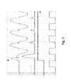
- Fig. 2 illustrates switching on of the supply to the transformer 5 after the transformer has been switched off with a significant magnetic remanance in its core with the phase control logic 3 and the pre-magnetisation control logic 8 disabled, such that the SCR power switch 4 is switched on at the positive going zero crossing point of the input sine waveform.
- channel 1 the input voltage rises but soon results in transformer core saturation, which results in a very large inrush current (see channel 4) which further results in serious distortion of the input supply voltage waveform and consequential voltage transients which can damage the supply load.
- the effect can also be seen to persist over several cycles of the supply voltage.
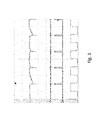
- Fig. 3 illustrates the operation of the pre-magnetisation modification of the SCR power switch 4 control circuitry, in accordance with the embodiment of the present invention.
- the AC supply causes the pre-magnetisation logic 8 to instruct the pre-magnetisation pulse generator 9 output a train of short duration SCR switching on pulses (see channel 3) to turn on the SCR power switch 4 just before the previous input voltage negative half sine wave reaches the zero voltage crossing point, which results in the SCR power switch 4 switching off. Note that this occurs on the negative half sine wave only.
- the correct switching on point is triggered by the pre-magnetisation logic 8 from the zero crossing point detector 2 (see channel 2).
- This train of short SCR switching on pulses on the negative half sine wave cycles only results in a small negative DC supply voltage being applied to the transformer, which ensures that the remanance in its core is small and slightly negative relative to the next turn on cycle, i.e. set to prevent transformer core saturation when the next positive sine wave supply voltage is applied at switching on.
- the train of pre-magnetisation pulses is switched off after a few cycles, whereupon the phased controlled switching on process by phase control logic 3 is allowed to initiate the switching on cycle.
- Fig. 4 shows the resultant oscilloscope trace of the four channels referred to previously when pre-magnetisation has been applied prior to the phase controlled switching on process.
- the input current surge on channel 4 and the input supply waveform distortion on channel 1 are drastically reduced compared to Fig. 2 .
- These traces were recorded after the transformer 5 had been deliberately set to have a high core remanance and connected to the system.
- Transformers supplying the electronics of subsea fluid extraction wells must be relied upon not to be the source of damaging voltage transients as they are located subsea, often beneath many kilometres of sea water. Consequently, they are very expensive to recover and repair.
- the present invention enables a substantial reduction of the risk of such damaging transients and thus potentially saves well operators major operating costs.
Landscapes
- Engineering & Computer Science (AREA)
- Power Engineering (AREA)
- Computer Networks & Wireless Communication (AREA)
- Signal Processing (AREA)
- Protection Of Transformers (AREA)
- Control Of Electrical Variables (AREA)
- Keying Circuit Devices (AREA)
- Direct Current Feeding And Distribution (AREA)
- Dc-Dc Converters (AREA)
Abstract
Description
- This invention relates to protecting against transients and inrush currents in a power control system, for example in a subsea fluid production well power control system.
- In subsea fluid production well power control systems, the voltage transients inherently associated with power on/off switching of inductive loads are potentially very damaging, because communication modems are directly coupled (connected electrically) to power lines in order to implement communication on power (COP) systems. High voltage transients may damage topside and subsea modems used in COP-based communication systems and topside and subsea power distribution transformers.
- The switching of AC power to a transformer is typically achieved in modern power control systems by semiconductor switches such as silicon controlled rectifiers (SCRs), triacs and gate turn off thyristors (GTOs). Prior art methods, such as those disclosed in
WO 01/03323 US5563459 ,US 2006/262881 andUS 4745515 , teach that to minimise inrush currents to the transformer primary, it is prudent to phase control the switching off of the semiconductor devices at the point of the AC waveform when the input current falls to zero, thereby ensuring that the magnetic remanance in the transformer core is zero and thus will not go into saturation when the AC supply is restored. However, this precaution has no value if the AC power source is inadvertently removed when current is flowing in the transformer primary, i.e. not a zero current phase controlled switching off, leaving remanance in the core, and potentially saturation and large inrush currents at restoration of the power source. - This situation is avoided by the invention disclosed in European Patent Application No.
11194360.1 - The present invention removes the need for a separate DC power supply to achieve the same pre-magnetisation.
- According to the invention from one aspect, there is provided a system for providing alternating current to at least one inductive load, the system including at least one switching means for switching power to said at least one load on and off, control means adapted for controlling said at least one switching means and a pre-magnetisation means, wherein the pre-magnetisation means is configured to generate pulses which cause the switching means to pre-magnetise the inductive load.
- According to the invention from another aspect, there is provided a method for providing alternating current to at least one inductive load, comprising the steps of:
- providing at least one switching means for switching power to said at least one load on and off;
- providing a control means adapted for controlling said at least one switching means; and
- using a pre-magnetisation means to generate pulses which cause the switching means to pre-magnetise the inductive load.
- The control means could comprise a zero voltage crossing comparator and phase control logic, and the output of said comparator could be used by the phase control logic to control the switching means to switch power to said at least one load on and off in phase with an input alternating current at a positive going crossing point of the alternating current waveform.
- The pre-magnetisation means could comprise a pre-magnetisation pulse generator.
- The pre-magnetisation means could comprise pre-magnetisation control logic configured to control the pre-magnetisation pulse generator to generate a train of pulses, wherein each pulse controls the switching means to switch power to said at least one load on prior to a negative going crossing point of the alternating current waveform.
- The alternating current waveform could comprise a sine wave.
- The at least one inductive load could comprise a winding of a transformer.
- A system according to the invention typically comprises a power control system for a subsea well and a method according to the invention typically is performed in such a system.
-
-
Fig. 1 is a schematic diagram of an embodiment of an electronic power control system in accordance with the present invention; -
Fig. 2 is an oscilloscope trace of voltage and current measured in the system ofFig. 1 at switching on, without pre-magnetisation of the transformer coil; -
Fig. 3 is an oscilloscope trace of voltage and current measured in the system ofFig. 1 when pre-magnetisation is applied prior to switching on; and -
Fig. 4 is an oscilloscope trace of voltage and current measured in the system ofFig. 1 at switching on, when pre-magnetisation has been applied prior to switching on. -
Fig. 1 shows a typical electronic power control system which employs a SCR power switch as the semiconductor switching device. In this example, the load is a subsea electronics module (SEM) which is part of a subsea fluid (e.g. hydrocarbon) production well control system. However, the present invention may be applied to any transformer fed system. - The power control system 1 conventionally consists of a zero
voltage crossing comparator 2, feedingphase control logic 3, which ensures that, under controlled conditions the switching on and off of a SCR power switch 4 occurs when the AC supply voltage is at the zero voltage crossing point. The switched power from the SCR power switch 4 feeds atransformer 5, the output of which feeds an AC toDC converter 6, which in turn supplies power to a DC load 7 (in this case, a SEM). The embodiment of the present invention is a modification to this arrangement, specifically including the addition of transformer pre-magnetisation logic 8, controlling apulse generator 9, which produces pre-magnetisation DC power generation by the SCR power switch 4 to thetransformer 5. -
Fig. 2 will now be described, in which: - Channel 1 represents the output voltage from the SCR power switch 4 input to the transformer 5 (via an isolation amplifier), with 500V per division. This is measured at point A in
Fig. 1 . -
Channel 2 represents the zero voltage crossing comparator output, with 5V per division. This is measured at point B inFig. 1 . -
Channel 3 represents the switch gate control signal for the SCR power switch 4, with 5V per division (and 5V representing switching on of SCR power switch 4). This is measured at point C inFig. 1 . - Channel 4 represents the load (SEM) current, with 5V per division, monitored by a DC current probe set to 1A per 10mV (100A per Volt). This is measured at point D in
Fig. 1 . -
Fig. 2 illustrates switching on of the supply to thetransformer 5 after the transformer has been switched off with a significant magnetic remanance in its core with thephase control logic 3 and the pre-magnetisation control logic 8 disabled, such that the SCR power switch 4 is switched on at the positive going zero crossing point of the input sine waveform. As can be seen on channel 1, the input voltage rises but soon results in transformer core saturation, which results in a very large inrush current (see channel 4) which further results in serious distortion of the input supply voltage waveform and consequential voltage transients which can damage the supply load. The effect can also be seen to persist over several cycles of the supply voltage. - It is this effect which results in potential damage due to transients when the supply is accidentally removed (e.g. by a circuit breaker opening) which cannot be prevented by conventional phase control of the SCR power switch 4.
-
Fig. 3 illustrates the operation of the pre-magnetisation modification of the SCR power switch 4 control circuitry, in accordance with the embodiment of the present invention. Prior to switching on occurring, following a power on command to the power control system 1, the AC supply causes the pre-magnetisation logic 8 to instruct thepre-magnetisation pulse generator 9 output a train of short duration SCR switching on pulses (see channel 3) to turn on the SCR power switch 4 just before the previous input voltage negative half sine wave reaches the zero voltage crossing point, which results in the SCR power switch 4 switching off. Note that this occurs on the negative half sine wave only. The correct switching on point is triggered by the pre-magnetisation logic 8 from the zero crossing point detector 2 (see channel 2). This train of short SCR switching on pulses on the negative half sine wave cycles only results in a small negative DC supply voltage being applied to the transformer, which ensures that the remanance in its core is small and slightly negative relative to the next turn on cycle, i.e. set to prevent transformer core saturation when the next positive sine wave supply voltage is applied at switching on. The train of pre-magnetisation pulses is switched off after a few cycles, whereupon the phased controlled switching on process byphase control logic 3 is allowed to initiate the switching on cycle. -
Fig. 4 shows the resultant oscilloscope trace of the four channels referred to previously when pre-magnetisation has been applied prior to the phase controlled switching on process. The input current surge on channel 4 and the input supply waveform distortion on channel 1 are drastically reduced compared toFig. 2 . These traces were recorded after thetransformer 5 had been deliberately set to have a high core remanance and connected to the system. - Transformers supplying the electronics of subsea fluid extraction wells must be relied upon not to be the source of damaging voltage transients as they are located subsea, often beneath many kilometres of sea water. Consequently, they are very expensive to recover and repair. The present invention enables a substantial reduction of the risk of such damaging transients and thus potentially saves well operators major operating costs.
Claims (13)
- A system for providing alternating current to at least one inductive load, the system including at least one switching means for switching power to said at least one load on and off, control means adapted for controlling said at least one switching means and a pre-magnetisation means, wherein the pre-magnetisation means is configured to generate pulses which cause the switching means to pre-magnetise the inductive load.
- A system according to claim 1, wherein the control means comprises a zero voltage crossing comparator and phase control logic, and wherein said the output of said comparator is used by the phase control logic to control the switching means to switch power to said at least one load on and off in phase with an input alternating current at a positive going crossing point of the alternating current waveform.
- A system according to claim 2, wherein the pre-magnetisation means comprises a pre-magnetisation pulse generator.
- A system according to claim 3, wherein the pre-magnetisation means comprises pre-magnetisation control logic configured to control the pre-magnetisation pulse generator to generate a train of pulses, wherein each pulse controls the switching means to switch power to said at least one load on prior to a negative going crossing point of the alternating current waveform.
- A system according to any preceding claim, wherein said at least one inductive load comprises a winding of a transformer.
- A system according to any preceding claim, wherein the alternating current waveform is a sine wave.
- A system according to any preceding claim, comprising a power control system for a subsea well.
- A method for providing alternating current to at least one inductive load, comprising the steps of:providing at least one switching means for switching power to said at least one load on and off;providing a control means adapted for controlling said at least one switching means; andusing a pre-magnetisation means to generate pulses which cause the switching means to pre-magnetise the inductive load.
- A method according to claim 8, wherein the control means comprises a zero voltage crossing comparator and phase control logic, and wherein said the output of said comparator is used by the phase control logic to control the switching means to switch power to said at least one load on and off in phase with an input alternating current at a positive going crossing point of the alternating current waveform.
- A method according to claim 9, wherein the pre-magnetisation means comprises a pre-magnetisation pulse generator.
- A method according to claim 10, wherein the pre-magnetisation means comprises pre-magnetisation control logic configured to control the pre-magnetisation pulse generator to generate a train of pulses, wherein each pulse controls the switching means to switch power to said at least one load on prior to a negative going crossing point of the alternating current waveform.
- A method according to any of claims 8 to 11, wherein said at least one inductive load comprises a winding of a transformer.
- A method according to any of claims 8 to 12, performed in a power control system for a subsea well.
Priority Applications (8)
| Application Number | Priority Date | Filing Date | Title |
|---|---|---|---|
| EP20130161586 EP2784894A1 (en) | 2013-03-28 | 2013-03-28 | Protecting against transients in a power control system |
| AU2014201699A AU2014201699B9 (en) | 2013-03-28 | 2014-03-21 | Protecting against transients in a power control system |
| SG10201400906RA SG10201400906RA (en) | 2013-03-28 | 2014-03-24 | Protecting against transients in a power control system |
| SG10201707961XA SG10201707961XA (en) | 2013-03-28 | 2014-03-24 | Protecting against transients in a power control system |
| BR102014007390A BR102014007390A2 (en) | 2013-03-28 | 2014-03-27 | system and method for providing alternating current |
| US14/227,199 US20140293488A1 (en) | 2013-03-28 | 2014-03-27 | Protecting against transients in a power control system |
| CN201410121535.4A CN104078917A (en) | 2013-03-28 | 2014-03-28 | Protecting against transients in a power control system |
| US16/440,649 US20210296886A1 (en) | 2013-03-28 | 2019-06-13 | Protecting against transients in a power control system |
Applications Claiming Priority (1)
| Application Number | Priority Date | Filing Date | Title |
|---|---|---|---|
| EP20130161586 EP2784894A1 (en) | 2013-03-28 | 2013-03-28 | Protecting against transients in a power control system |
Publications (1)
| Publication Number | Publication Date |
|---|---|
| EP2784894A1 true EP2784894A1 (en) | 2014-10-01 |
Family
ID=48049793
Family Applications (1)
| Application Number | Title | Priority Date | Filing Date |
|---|---|---|---|
| EP20130161586 Withdrawn EP2784894A1 (en) | 2013-03-28 | 2013-03-28 | Protecting against transients in a power control system |
Country Status (6)
| Country | Link |
|---|---|
| US (2) | US20140293488A1 (en) |
| EP (1) | EP2784894A1 (en) |
| CN (1) | CN104078917A (en) |
| AU (1) | AU2014201699B9 (en) |
| BR (1) | BR102014007390A2 (en) |
| SG (2) | SG10201707961XA (en) |
Cited By (1)
| Publication number | Priority date | Publication date | Assignee | Title |
|---|---|---|---|---|
| CN104538222A (en) * | 2014-12-27 | 2015-04-22 | 中国西电电气股份有限公司 | High-voltage switch phase selection controller based on artificial neural network and method |
Citations (7)
| Publication number | Priority date | Publication date | Assignee | Title |
|---|---|---|---|---|
| US4745515A (en) | 1986-05-30 | 1988-05-17 | Robertshaw Controls Company | Electrically operated control device and system for an appliance and method of operating the same |
| US5345359A (en) * | 1991-12-21 | 1994-09-06 | Fraunhofer-Gesellschaft Zur Forderung Der Angewandten | Process for the reduction of the switch-on surge in current during the operation of an inductive load |
| US5563459A (en) | 1989-11-15 | 1996-10-08 | Hitachi, Ltd. | Apparatus for controlling opening and closing timings of a switching device in an electric power system |
| WO2001003323A1 (en) | 1999-07-01 | 2001-01-11 | The Autonomous Well Company Limited | Power line communication system |
| EP1119436A1 (en) | 1998-10-07 | 2001-08-01 | Fraunhofer-Gesellschaft zur Förderung der angewandten Forschung e.V. | Method for shaping materials with plasma-inducing high-energy radiation |
| DE10016999A1 (en) * | 2000-04-05 | 2001-10-18 | Siemens Ag | Switching method for reactive load connected to AC supply |
| US20060262881A1 (en) | 2005-05-20 | 2006-11-23 | Yehuda Cern | Power line communications interface and surge protector |
Family Cites Families (5)
| Publication number | Priority date | Publication date | Assignee | Title |
|---|---|---|---|---|
| CN86107818A (en) * | 1986-11-14 | 1988-05-25 | 通用电气环境服务公司 | The protective device of switching device in the capacity load pulse generating circuit |
| CN1009979B (en) * | 1987-10-03 | 1990-10-10 | 金恩光 | Method for controlling thyristors and equipment theirof |
| DE4217866C1 (en) * | 1992-05-29 | 1993-05-13 | Fraunhofer-Gesellschaft Zur Foerderung Der Angewandten Forschung Ev, 8000 Muenchen, De | |
| US7511934B2 (en) * | 2005-12-02 | 2009-03-31 | Electronic Systems Protection, Inc. | System and method for conditioning a power supply transmission for supply to a load circuit |
| EP2673868B1 (en) * | 2011-02-10 | 2015-05-20 | PAI Capital LLC | Input current shaping for transition and discontinuous mode power converter |
-
2013
- 2013-03-28 EP EP20130161586 patent/EP2784894A1/en not_active Withdrawn
-
2014
- 2014-03-21 AU AU2014201699A patent/AU2014201699B9/en not_active Ceased
- 2014-03-24 SG SG10201707961XA patent/SG10201707961XA/en unknown
- 2014-03-24 SG SG10201400906RA patent/SG10201400906RA/en unknown
- 2014-03-27 BR BR102014007390A patent/BR102014007390A2/en not_active Application Discontinuation
- 2014-03-27 US US14/227,199 patent/US20140293488A1/en not_active Abandoned
- 2014-03-28 CN CN201410121535.4A patent/CN104078917A/en active Pending
-
2019
- 2019-06-13 US US16/440,649 patent/US20210296886A1/en not_active Abandoned
Patent Citations (7)
| Publication number | Priority date | Publication date | Assignee | Title |
|---|---|---|---|---|
| US4745515A (en) | 1986-05-30 | 1988-05-17 | Robertshaw Controls Company | Electrically operated control device and system for an appliance and method of operating the same |
| US5563459A (en) | 1989-11-15 | 1996-10-08 | Hitachi, Ltd. | Apparatus for controlling opening and closing timings of a switching device in an electric power system |
| US5345359A (en) * | 1991-12-21 | 1994-09-06 | Fraunhofer-Gesellschaft Zur Forderung Der Angewandten | Process for the reduction of the switch-on surge in current during the operation of an inductive load |
| EP1119436A1 (en) | 1998-10-07 | 2001-08-01 | Fraunhofer-Gesellschaft zur Förderung der angewandten Forschung e.V. | Method for shaping materials with plasma-inducing high-energy radiation |
| WO2001003323A1 (en) | 1999-07-01 | 2001-01-11 | The Autonomous Well Company Limited | Power line communication system |
| DE10016999A1 (en) * | 2000-04-05 | 2001-10-18 | Siemens Ag | Switching method for reactive load connected to AC supply |
| US20060262881A1 (en) | 2005-05-20 | 2006-11-23 | Yehuda Cern | Power line communications interface and surge protector |
Cited By (2)
| Publication number | Priority date | Publication date | Assignee | Title |
|---|---|---|---|---|
| CN104538222A (en) * | 2014-12-27 | 2015-04-22 | 中国西电电气股份有限公司 | High-voltage switch phase selection controller based on artificial neural network and method |
| CN104538222B (en) * | 2014-12-27 | 2016-09-28 | 中国西电电气股份有限公司 | High-voltage switch gear phase-controlled device based on artificial neural network and method |
Also Published As
| Publication number | Publication date |
|---|---|
| SG10201707961XA (en) | 2017-11-29 |
| BR102014007390A2 (en) | 2015-12-01 |
| CN104078917A (en) | 2014-10-01 |
| AU2014201699B9 (en) | 2017-09-28 |
| US20210296886A1 (en) | 2021-09-23 |
| SG10201400906RA (en) | 2014-10-30 |
| US20140293488A1 (en) | 2014-10-02 |
| AU2014201699B2 (en) | 2017-09-07 |
| AU2014201699A1 (en) | 2014-10-16 |
Similar Documents
| Publication | Publication Date | Title |
|---|---|---|
| US10763742B2 (en) | Control of voltage source converters | |
| US20170149366A1 (en) | Methods and apparatus for soft operation of transformers using auxiliary winding excitation | |
| EP2999075B1 (en) | Power supply with surge voltage protection | |
| RU136919U1 (en) | MAGNETIC CONTROLLED BYPASS REACTOR | |
| JP2016533157A (en) | System and method for providing isolated power to a gate drive circuit in a solid state current limiter | |
| US11848550B2 (en) | Semiconductor circuit breaker and circuit breaking device | |
| US20210296886A1 (en) | Protecting against transients in a power control system | |
| US9520714B2 (en) | Protecting an operation control unit connected to an electric machine via a long cable | |
| CN105467307B (en) | Flexible DC power transmission engineering voltage source converter valve IGBT overcurrent turns off experimental rig | |
| US9130372B2 (en) | Protecting against transients in a communication system | |
| Hoevenaars et al. | Preventing AC drive failures due to commutation notches on a drilling rig | |
| EP2608357A1 (en) | Protecting against transients in a communication system | |
| Asghar et al. | Reduction of three-phase transformer magnetizing inrush current by use of point on wave switching | |
| EP3261243A1 (en) | Power conversion device and initial charging method therefor | |
| CN107533099A (en) | For the circuit arrangement and its method of testing of secure digital output switching terminal, include the output module of the type digital means | |
| AU2015365660B2 (en) | A circuit for a voltage power optimiser | |
| US10439393B2 (en) | Switch systems for controlling conduction of multi-phase current | |
| CA2930066A1 (en) | Device and method for reducing a magnetic unidirectional flux component in the core of a three-phase transformer | |
| RU2683266C1 (en) | PROTECTION METHOD OF CONVERTING PLANT WITH TRANSFORMER WITH 2n SECONDARY WINDING AND 2n COIL RECTIFIER | |
| RU2658346C1 (en) | Method of controlled shunt reactor commutation | |
| EP2451079A1 (en) | Soft start for AC power switching | |
| Lazarev et al. | Controlled switching of transformers | |
| CN111740397A (en) | Method and apparatus for operating a power distribution system |
Legal Events
| Date | Code | Title | Description |
|---|---|---|---|
| 17P | Request for examination filed |
Effective date: 20130328 |
|
| AK | Designated contracting states |
Kind code of ref document: A1 Designated state(s): AL AT BE BG CH CY CZ DE DK EE ES FI FR GB GR HR HU IE IS IT LI LT LU LV MC MK MT NL NO PL PT RO RS SE SI SK SM TR |
|
| AX | Request for extension of the european patent |
Extension state: BA ME |
|
| PUAI | Public reference made under article 153(3) epc to a published international application that has entered the european phase |
Free format text: ORIGINAL CODE: 0009012 |
|
| R17P | Request for examination filed (corrected) |
Effective date: 20150402 |
|
| RBV | Designated contracting states (corrected) |
Designated state(s): AL AT BE BG CH CY CZ DE DK EE ES FI FR GB GR HR HU IE IS IT LI LT LU LV MC MK MT NL NO PL PT RO RS SE SI SK SM TR |
|
| RAP1 | Party data changed (applicant data changed or rights of an application transferred) |
Owner name: GE OIL & GAS UK LIMITED |
|
| 17Q | First examination report despatched |
Effective date: 20151126 |
|
| STAA | Information on the status of an ep patent application or granted ep patent |
Free format text: STATUS: EXAMINATION IS IN PROGRESS |
|
| STAA | Information on the status of an ep patent application or granted ep patent |
Free format text: STATUS: EXAMINATION IS IN PROGRESS |
|
| STAA | Information on the status of an ep patent application or granted ep patent |
Free format text: STATUS: EXAMINATION IS IN PROGRESS |
|
| RAP3 | Party data changed (applicant data changed or rights of an application transferred) |
Owner name: BAKER HUGHES ENERGY TECHNOLOGY UK LIMITED |
|
| GRAP | Despatch of communication of intention to grant a patent |
Free format text: ORIGINAL CODE: EPIDOSNIGR1 |
|
| STAA | Information on the status of an ep patent application or granted ep patent |
Free format text: STATUS: GRANT OF PATENT IS INTENDED |
|
| INTG | Intention to grant announced |
Effective date: 20230425 |
|
| P01 | Opt-out of the competence of the unified patent court (upc) registered |
Effective date: 20230526 |
|
| STAA | Information on the status of an ep patent application or granted ep patent |
Free format text: STATUS: THE APPLICATION IS DEEMED TO BE WITHDRAWN |
|
| 18D | Application deemed to be withdrawn |
Effective date: 20230906 |