EP2784836A1 - Piezoelectric/electrostrictive element and method for manufacturing the same - Google Patents
Piezoelectric/electrostrictive element and method for manufacturing the same Download PDFInfo
- Publication number
- EP2784836A1 EP2784836A1 EP20140159739 EP14159739A EP2784836A1 EP 2784836 A1 EP2784836 A1 EP 2784836A1 EP 20140159739 EP20140159739 EP 20140159739 EP 14159739 A EP14159739 A EP 14159739A EP 2784836 A1 EP2784836 A1 EP 2784836A1
- Authority
- EP
- European Patent Office
- Prior art keywords
- electrode
- hole
- microns
- piezoelectric
- piezoelectric body
- Prior art date
- Legal status (The legal status is an assumption and is not a legal conclusion. Google has not performed a legal analysis and makes no representation as to the accuracy of the status listed.)
- Withdrawn
Links
- 238000000034 method Methods 0.000 title claims description 35
- 238000004519 manufacturing process Methods 0.000 title claims description 10
- 238000004891 communication Methods 0.000 claims abstract description 3
- 238000005530 etching Methods 0.000 claims description 38
- 239000007772 electrode material Substances 0.000 claims description 26
- 238000000576 coating method Methods 0.000 claims description 9
- 239000011248 coating agent Substances 0.000 claims description 3
- 239000010408 film Substances 0.000 description 22
- 229920002120 photoresistant polymer Polymers 0.000 description 21
- 239000000758 substrate Substances 0.000 description 20
- 239000007788 liquid Substances 0.000 description 14
- 239000004020 conductor Substances 0.000 description 10
- 238000010304 firing Methods 0.000 description 8
- 239000000463 material Substances 0.000 description 8
- 238000005259 measurement Methods 0.000 description 8
- BASFCYQUMIYNBI-UHFFFAOYSA-N platinum Chemical compound [Pt] BASFCYQUMIYNBI-UHFFFAOYSA-N 0.000 description 8
- 238000001878 scanning electron micrograph Methods 0.000 description 8
- 230000003746 surface roughness Effects 0.000 description 7
- 238000012545 processing Methods 0.000 description 6
- 238000005516 engineering process Methods 0.000 description 5
- 230000010355 oscillation Effects 0.000 description 5
- 239000007921 spray Substances 0.000 description 5
- DDFHBQSCUXNBSA-UHFFFAOYSA-N 5-(5-carboxythiophen-2-yl)thiophene-2-carboxylic acid Chemical compound S1C(C(=O)O)=CC=C1C1=CC=C(C(O)=O)S1 DDFHBQSCUXNBSA-UHFFFAOYSA-N 0.000 description 4
- VEXZGXHMUGYJMC-UHFFFAOYSA-N Hydrochloric acid Chemical compound Cl VEXZGXHMUGYJMC-UHFFFAOYSA-N 0.000 description 4
- KDLHZDBZIXYQEI-UHFFFAOYSA-N Palladium Chemical compound [Pd] KDLHZDBZIXYQEI-UHFFFAOYSA-N 0.000 description 4
- 230000001133 acceleration Effects 0.000 description 4
- WMWLMWRWZQELOS-UHFFFAOYSA-N bismuth(iii) oxide Chemical compound O=[Bi]O[Bi]=O WMWLMWRWZQELOS-UHFFFAOYSA-N 0.000 description 4
- 239000008139 complexing agent Substances 0.000 description 4
- 239000011810 insulating material Substances 0.000 description 4
- 229910000510 noble metal Inorganic materials 0.000 description 4
- 238000000206 photolithography Methods 0.000 description 4
- 239000000843 powder Substances 0.000 description 4
- 239000004094 surface-active agent Substances 0.000 description 4
- 239000002562 thickening agent Substances 0.000 description 4
- 238000011156 evaluation Methods 0.000 description 3
- 238000011049 filling Methods 0.000 description 3
- 239000011521 glass Substances 0.000 description 3
- 239000010931 gold Substances 0.000 description 3
- 229910052697 platinum Inorganic materials 0.000 description 3
- YCKRFDGAMUMZLT-UHFFFAOYSA-N Fluorine atom Chemical compound [F] YCKRFDGAMUMZLT-UHFFFAOYSA-N 0.000 description 2
- 239000002253 acid Substances 0.000 description 2
- 230000002378 acidificating effect Effects 0.000 description 2
- 239000007864 aqueous solution Substances 0.000 description 2
- 239000011230 binding agent Substances 0.000 description 2
- 230000015572 biosynthetic process Effects 0.000 description 2
- 230000003197 catalytic effect Effects 0.000 description 2
- 229920001940 conductive polymer Polymers 0.000 description 2
- 230000008602 contraction Effects 0.000 description 2
- 239000010949 copper Substances 0.000 description 2
- 239000002270 dispersing agent Substances 0.000 description 2
- 238000001035 drying Methods 0.000 description 2
- 238000009713 electroplating Methods 0.000 description 2
- 229910052731 fluorine Inorganic materials 0.000 description 2
- 239000011737 fluorine Substances 0.000 description 2
- 230000005764 inhibitory process Effects 0.000 description 2
- XMFOQHDPRMAJNU-UHFFFAOYSA-N lead(II,IV) oxide Inorganic materials O1[Pb]O[Pb]11O[Pb]O1 XMFOQHDPRMAJNU-UHFFFAOYSA-N 0.000 description 2
- 229910052763 palladium Inorganic materials 0.000 description 2
- 238000007650 screen-printing Methods 0.000 description 2
- 238000005245 sintering Methods 0.000 description 2
- 239000002002 slurry Substances 0.000 description 2
- 239000000243 solution Substances 0.000 description 2
- 238000005507 spraying Methods 0.000 description 2
- 238000009736 wetting Methods 0.000 description 2
- RYGMFSIKBFXOCR-UHFFFAOYSA-N Copper Chemical compound [Cu] RYGMFSIKBFXOCR-UHFFFAOYSA-N 0.000 description 1
- 229910052581 Si3N4 Inorganic materials 0.000 description 1
- BQCADISMDOOEFD-UHFFFAOYSA-N Silver Chemical compound [Ag] BQCADISMDOOEFD-UHFFFAOYSA-N 0.000 description 1
- 239000000956 alloy Substances 0.000 description 1
- 229910045601 alloy Inorganic materials 0.000 description 1
- 238000005422 blasting Methods 0.000 description 1
- 239000006229 carbon black Substances 0.000 description 1
- 239000003054 catalyst Substances 0.000 description 1
- 229910010293 ceramic material Inorganic materials 0.000 description 1
- 229910052802 copper Inorganic materials 0.000 description 1
- PMHQVHHXPFUNSP-UHFFFAOYSA-M copper(1+);methylsulfanylmethane;bromide Chemical compound Br[Cu].CSC PMHQVHHXPFUNSP-UHFFFAOYSA-M 0.000 description 1
- 238000007872 degassing Methods 0.000 description 1
- 238000005238 degreasing Methods 0.000 description 1
- KZHJGOXRZJKJNY-UHFFFAOYSA-N dioxosilane;oxo(oxoalumanyloxy)alumane Chemical compound O=[Si]=O.O=[Si]=O.O=[Al]O[Al]=O.O=[Al]O[Al]=O.O=[Al]O[Al]=O KZHJGOXRZJKJNY-UHFFFAOYSA-N 0.000 description 1
- 239000012153 distilled water Substances 0.000 description 1
- 230000000694 effects Effects 0.000 description 1
- 239000002003 electrode paste Substances 0.000 description 1
- PCHJSUWPFVWCPO-UHFFFAOYSA-N gold Chemical compound [Au] PCHJSUWPFVWCPO-UHFFFAOYSA-N 0.000 description 1
- 229910052737 gold Inorganic materials 0.000 description 1
- 238000010030 laminating Methods 0.000 description 1
- HFGPZNIAWCZYJU-UHFFFAOYSA-N lead zirconate titanate Chemical compound [O-2].[O-2].[O-2].[O-2].[O-2].[Ti+4].[Zr+4].[Pb+2] HFGPZNIAWCZYJU-UHFFFAOYSA-N 0.000 description 1
- 239000000395 magnesium oxide Substances 0.000 description 1
- CPLXHLVBOLITMK-UHFFFAOYSA-N magnesium oxide Inorganic materials [Mg]=O CPLXHLVBOLITMK-UHFFFAOYSA-N 0.000 description 1
- AXZKOIWUVFPNLO-UHFFFAOYSA-N magnesium;oxygen(2-) Chemical compound [O-2].[Mg+2] AXZKOIWUVFPNLO-UHFFFAOYSA-N 0.000 description 1
- 239000000203 mixture Substances 0.000 description 1
- 238000012986 modification Methods 0.000 description 1
- 230000004048 modification Effects 0.000 description 1
- 229910052863 mullite Inorganic materials 0.000 description 1
- TWNQGVIAIRXVLR-UHFFFAOYSA-N oxo(oxoalumanyloxy)alumane Chemical compound O=[Al]O[Al]=O TWNQGVIAIRXVLR-UHFFFAOYSA-N 0.000 description 1
- RVTZCBVAJQQJTK-UHFFFAOYSA-N oxygen(2-);zirconium(4+) Chemical compound [O-2].[O-2].[Zr+4] RVTZCBVAJQQJTK-UHFFFAOYSA-N 0.000 description 1
- 229910002077 partially stabilized zirconia Inorganic materials 0.000 description 1
- 239000002245 particle Substances 0.000 description 1
- 238000000059 patterning Methods 0.000 description 1
- 239000004014 plasticizer Substances 0.000 description 1
- 238000002360 preparation method Methods 0.000 description 1
- 230000001681 protective effect Effects 0.000 description 1
- 239000011347 resin Substances 0.000 description 1
- 229920005989 resin Polymers 0.000 description 1
- 230000000717 retained effect Effects 0.000 description 1
- HQVNEWCFYHHQES-UHFFFAOYSA-N silicon nitride Chemical compound N12[Si]34N5[Si]62N3[Si]51N64 HQVNEWCFYHHQES-UHFFFAOYSA-N 0.000 description 1
- 229910052709 silver Inorganic materials 0.000 description 1
- 239000004332 silver Substances 0.000 description 1
- 238000004528 spin coating Methods 0.000 description 1
- 239000010409 thin film Substances 0.000 description 1
- XLYOFNOQVPJJNP-UHFFFAOYSA-N water Chemical compound O XLYOFNOQVPJJNP-UHFFFAOYSA-N 0.000 description 1
- 229910001928 zirconium oxide Inorganic materials 0.000 description 1
Images


Classifications
-
- B—PERFORMING OPERATIONS; TRANSPORTING
- B41—PRINTING; LINING MACHINES; TYPEWRITERS; STAMPS
- B41J—TYPEWRITERS; SELECTIVE PRINTING MECHANISMS, i.e. MECHANISMS PRINTING OTHERWISE THAN FROM A FORME; CORRECTION OF TYPOGRAPHICAL ERRORS
- B41J2/00—Typewriters or selective printing mechanisms characterised by the printing or marking process for which they are designed
- B41J2/005—Typewriters or selective printing mechanisms characterised by the printing or marking process for which they are designed characterised by bringing liquid or particles selectively into contact with a printing material
- B41J2/01—Ink jet
- B41J2/135—Nozzles
- B41J2/16—Production of nozzles
- B41J2/1607—Production of print heads with piezoelectric elements
- B41J2/161—Production of print heads with piezoelectric elements of film type, deformed by bending and disposed on a diaphragm
-
- B—PERFORMING OPERATIONS; TRANSPORTING
- B41—PRINTING; LINING MACHINES; TYPEWRITERS; STAMPS
- B41J—TYPEWRITERS; SELECTIVE PRINTING MECHANISMS, i.e. MECHANISMS PRINTING OTHERWISE THAN FROM A FORME; CORRECTION OF TYPOGRAPHICAL ERRORS
- B41J2/00—Typewriters or selective printing mechanisms characterised by the printing or marking process for which they are designed
- B41J2/005—Typewriters or selective printing mechanisms characterised by the printing or marking process for which they are designed characterised by bringing liquid or particles selectively into contact with a printing material
- B41J2/01—Ink jet
- B41J2/135—Nozzles
- B41J2/16—Production of nozzles
- B41J2/1621—Manufacturing processes
- B41J2/1626—Manufacturing processes etching
- B41J2/1629—Manufacturing processes etching wet etching
-
- B—PERFORMING OPERATIONS; TRANSPORTING
- B41—PRINTING; LINING MACHINES; TYPEWRITERS; STAMPS
- B41J—TYPEWRITERS; SELECTIVE PRINTING MECHANISMS, i.e. MECHANISMS PRINTING OTHERWISE THAN FROM A FORME; CORRECTION OF TYPOGRAPHICAL ERRORS
- B41J2/00—Typewriters or selective printing mechanisms characterised by the printing or marking process for which they are designed
- B41J2/005—Typewriters or selective printing mechanisms characterised by the printing or marking process for which they are designed characterised by bringing liquid or particles selectively into contact with a printing material
- B41J2/01—Ink jet
- B41J2/135—Nozzles
- B41J2/16—Production of nozzles
- B41J2/1621—Manufacturing processes
- B41J2/1631—Manufacturing processes photolithography
-
- B—PERFORMING OPERATIONS; TRANSPORTING
- B41—PRINTING; LINING MACHINES; TYPEWRITERS; STAMPS
- B41J—TYPEWRITERS; SELECTIVE PRINTING MECHANISMS, i.e. MECHANISMS PRINTING OTHERWISE THAN FROM A FORME; CORRECTION OF TYPOGRAPHICAL ERRORS
- B41J2/00—Typewriters or selective printing mechanisms characterised by the printing or marking process for which they are designed
- B41J2/005—Typewriters or selective printing mechanisms characterised by the printing or marking process for which they are designed characterised by bringing liquid or particles selectively into contact with a printing material
- B41J2/01—Ink jet
- B41J2/135—Nozzles
- B41J2/16—Production of nozzles
- B41J2/1621—Manufacturing processes
- B41J2/164—Manufacturing processes thin film formation
- B41J2/1645—Manufacturing processes thin film formation thin film formation by spincoating
-
- H—ELECTRICITY
- H10—SEMICONDUCTOR DEVICES; ELECTRIC SOLID-STATE DEVICES NOT OTHERWISE PROVIDED FOR
- H10N—ELECTRIC SOLID-STATE DEVICES NOT OTHERWISE PROVIDED FOR
- H10N30/00—Piezoelectric or electrostrictive devices
- H10N30/01—Manufacture or treatment
- H10N30/06—Forming electrodes or interconnections, e.g. leads or terminals
-
- H—ELECTRICITY
- H10—SEMICONDUCTOR DEVICES; ELECTRIC SOLID-STATE DEVICES NOT OTHERWISE PROVIDED FOR
- H10N—ELECTRIC SOLID-STATE DEVICES NOT OTHERWISE PROVIDED FOR
- H10N30/00—Piezoelectric or electrostrictive devices
- H10N30/20—Piezoelectric or electrostrictive devices with electrical input and mechanical output, e.g. functioning as actuators or vibrators
- H10N30/204—Piezoelectric or electrostrictive devices with electrical input and mechanical output, e.g. functioning as actuators or vibrators using bending displacement, e.g. unimorph, bimorph or multimorph cantilever or membrane benders
- H10N30/2047—Membrane type
-
- H—ELECTRICITY
- H10—SEMICONDUCTOR DEVICES; ELECTRIC SOLID-STATE DEVICES NOT OTHERWISE PROVIDED FOR
- H10N—ELECTRIC SOLID-STATE DEVICES NOT OTHERWISE PROVIDED FOR
- H10N30/00—Piezoelectric or electrostrictive devices
- H10N30/80—Constructional details
- H10N30/87—Electrodes or interconnections, e.g. leads or terminals
- H10N30/875—Further connection or lead arrangements, e.g. flexible wiring boards, terminal pins
-
- Y—GENERAL TAGGING OF NEW TECHNOLOGICAL DEVELOPMENTS; GENERAL TAGGING OF CROSS-SECTIONAL TECHNOLOGIES SPANNING OVER SEVERAL SECTIONS OF THE IPC; TECHNICAL SUBJECTS COVERED BY FORMER USPC CROSS-REFERENCE ART COLLECTIONS [XRACs] AND DIGESTS
- Y10—TECHNICAL SUBJECTS COVERED BY FORMER USPC
- Y10T—TECHNICAL SUBJECTS COVERED BY FORMER US CLASSIFICATION
- Y10T29/00—Metal working
- Y10T29/42—Piezoelectric device making
Definitions
- the technology disclosed herein relates to a piezoelectric/electrostrictive element provided with a through-hole electrode, and to a method for manufacturing the same.
- a conventional piezoelectric/electrostrictive element is provided with a through-hole electrode that is filled into a through-hole of a piezoelectric body (see Japanese Patent Application Laid-Open No. 2008-211047 and No. 2005-51840 ).
- the piezoelectric/electrostrictive element includes a first upper electrode, a second upper electrode and a lower electrode.
- the first upper electrode and the second upper electrode are formed on an upper surface of the piezoelectric body.
- the lower electrode is formed on a lower surface of the piezoelectric body.
- the through-hole electrode is connected to the lower electrode and the second upper electrode.
- This type of piezoelectric/electrostrictive element enables application of a voltage to the first upper electrode and the lower electrode by application of a voltage to the first upper electrode and the second upper electrode.
- the through-hole electrode is preferably configured to use an electrode material such as an electrode paste that contains a conductive material, and filling is preferably executed by use of a coating method such as screen printing or the like.
- the through-hole electrode is formed by a thin coat of electrode material onto an inner side surface of the through-hole.
- the object of the technology disclosed herein is to provide a piezoelectric/electrostrictive element and a method for manufacturing the same that enables inhibition of disconnection of a through-hole electrode.
- a piezoelectric/electrostrictive element has a piezoelectric body, a through-hole electrode, a first electrode, a second electrode, a third electrode.
- the piezoelectric body includes a through-hole in communication with a first main surface and a second main surface.
- the through-hole electrode is formed on an inner side surface of the through-hole.
- the first electrode is formed on the first main surface of the piezoelectric body.
- the first electrode is connected to the through-hole electrode.
- the second electrode is formed on the second main surface of the piezoelectric body.
- the second electrode is connected to the through-hole electrode.
- the third electrode is formed on the second main surface of the piezoelectric body.
- the third electrode is isolated from the second electrode.
- a calculated average roughness in the inner side surface is larger than 0.11 microns and smaller than 16 microns.
- a maximum height roughness in the inner side surface is larger than 0.2 microns and smaller than 20 microns.
- the technology disclosed herein provides a piezoelectric/electrostrictive element and a method for manufacturing the same that enables inhibition of disconnection of a through-hole electrode.
- the piezoelectric/electrostrictive element can be applied to various uses such as an oscillation circuit, various types of sensors or an injector actuator.
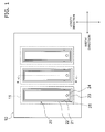
- FIG. 1 is a plan view illustrating a configuration of the actuator 100.
- FIG. 2 is a sectional view along the line X-X in FIG. 1 .
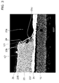
- FIG. 3 illustrates a SEM image of a cross section of the piezoelectric/electrostrictive element.
- the direction in which the piezoelectric/electrostrictive element 20 extends is termed the "length direction", and the direction that is orthogonal to the length direction is termed the "width direction”.
- the direction that is orthogonal to the length direction and the width direction is termed the "thickness direction”.
- the actuator 100 includes a substrate 10 and a plurality of piezoelectric/electrostrictive elements 20.
- the substrate 10 is a plate-shaped fired body.
- the substrate 10 is configured from an insulating material.
- the insulating material used to configure the substrate 10 includes for example, stabilized zirconium oxide, aluminum oxide, magnesium oxide, mullite, aluminum nitride and silicon nitride, or the like.
- the insulating material that configures the substrate 10 is not limited to a ceramic material and may be configured by a glass material, a resin material, or the like. Furthermore, the particles that configure the substrate 10 may be a monocrystal, a polycrystal, or an amorphous material.
- the substrate 10 includes a diaphragm 11, a pressure chamber 12 and a discharge nozzle 13, and an ink guide port 14.
- the diaphragm 11 is a thin plate configured to support the piezoelectric/electrostrictive element 20.
- the diaphragm 11 vibrates (displaces) in the thickness direction in response to expansion and contraction of the piezoelectric/electrostrictive element 20.
- the pressure chamber 12 is a cavity provided below the diaphragm 11.
- the pressure chamber 12 retains ink injected from an ink guide port 14.
- the discharge nozzle 13 extends downwardly from the pressure chamber 12. The ink retained in the pressure chamber 12 is discharged from the discharge nozzle 13 in response to the vibration of the diaphragm 11.
- the piezoelectric/electrostrictive element 20 extends in the length direction on the substrate 10. A plurality of piezoelectric/electrostrictive elements 20 is mutually aligned in parallel.
- the piezoelectric/electrostrictive element 20 includes a first lower electrode 21, a second lower electrode 22, a piezoelectric body 23, a through-hole electrode 24, and an upper electrode 25.
- the upper electrode 25 is an example of "a first electrode”
- the first lower electrode 21 is an example of "a second electrode”
- the second lower electrode 22 is an example of "a third electrode”.
- the first lower electrode 21 is a thin film-shaped fired body that is disposed on the diaphragm 11.
- the first lower electrode 21 is connected to the through-hole electrode 24.
- One end portion of the first lower electrode 21 projects from one end portion of the piezoelectric body 23.
- the first lower electrode 21 is formed a size smaller than the second lower electrode 22.
- the length of the first lower electrode 21 is for example 1 micron to 500 microns.
- the width of the first lower electrode 21 is for example 30 microns to 500 microns.
- the thickness of the first lower electrode 21 is for example 0.1 microns to 10.0 microns.
- the first lower electrode 21 is configured from an acid resistant conductive material.
- the conductive material includes for example noble metals such as platinum (Pt) or the like, in addition to conductive polymers and conductive oxides.
- the second lower electrode 22 is a thin film-shaped fired body disposed on the diaphragm 11.
- the second lower electrode 22 is separated from the first lower electrode 21 and is not connected to the through-hole electrode 24.
- One end portion of the second lower electrode 22 projects from the other end potion of the piezoelectric body 23.
- the second lower electrode 22 is formed with a size that is larger than the first lower electrode 21.
- the length of the second lower electrode 22 is for example 500 microns to 5000 microns.
- the width of the second lower electrode 22 is for example 30 microns to 500 microns.
- the thickness of the second lower electrode 22 is for example 0.1 microns to 10.0 microns.
- the second lower electrode 22 may be formed using the same conductive material as the first lower electrode 21.
- the piezoelectric body 23 is a thin film-shaped fired body disposed on the first and second lower electrodes 21, 22.
- the piezoelectric body 23 includes a first main surface 23S and a second main surface 23T.
- the upper electrode 25 is disposed on the first main surface 23S.
- the first and second lower electrodes 21, 22 are disposed on the second main surface 23T.
- a voltage is applied to the first and second lower electrodes 21, 22, a voltage is applied to the upper electrode 25 and the second lower electrode 22, and consequently, the piezoelectric body 23 contracts and expands in a direction that is perpendicular to the thickness direction.
- the diaphragm 11 vibrates (displaces) in the thickness direction in response to the contraction or expansion of the piezoelectric body 23.
- the piezoelectric body 23 is formed with a size that is smaller than or equal to the combined size of the first and second lower electrodes 21, 22.
- the length of the piezoelectric body 23 is for example 500 microns to 5000 microns.
- the width of the piezoelectric body 23 is for example 30 microns to 500 microns.
- the thickness of the piezoelectric body 23 is for example 0.5 microns to 20.0 microns.
- the piezoelectric body 23 is configured from a polycrystalline piezoelectric material.
- the piezoelectric material includes for example lead titanate zirconate (PZT), or the like.
- the piezoelectric body 23 has a through-hole 23a that communicates with the first main surface 23S and the second main surface 23T.
- the through-hole 23a may be formed with a circular shape of 1.0 micron to 500 microns, there is no limitation on the planar shape or size of the through-hole 23a.
- the through-hole 23a may be configured as a quadrilateral, or in a linear configuration.
- a plurality of recessed portions 23b is formed in an inner side surface 23U of the through-hole 23a.
- the recessed portions 23b are preferably formed on the whole surface of the inner side surface 23U, however there is no requirement for a uniform disposition.
- the shape, aperture size and depth or the like of the recessed portions 23b may differ on an individual basis.
- the shape of the recessed portions 23b for example may be configured as a circle, an oval, or a rectangle, and there is no limitation in this regard.
- the circle correspondence diameter of the aperture size of the recessed portion 23b may be 0.1 micron to 20 microns, and the depth of the recessed portions 23b may be 0.1 microns to 30 microns.
- the calculated average roughness Ra of the inner side surface 23U formed by the plurality of recessed portions 23b is preferably greater than 0.11 microns and less than 16 microns.
- the maximum height roughness Rz of the inner side surface 23U is preferably larger than 0.2 microns and smaller than 20 microns.
- the calculated average roughness Ra and the maximum height roughness Rz for example may be calculated using a white-light interference non-contact surface roughness meter.
- An inner portion of the recessed portions 23b is configured as a cavity. That is to say, the inner portion of the recessed portions 23b is not filled with the through-hole electrode 24. However, as described below, electrode material is filled into the inner portion of the recessed portions 23b in the coating processing step of the electrode material, and thereafter, the electrode material in the recessed portions 23b moves to the outside in the firing processing step of the electrode material.
- FIG. 3 illustrates a straight line L1 that is linear fitted to the inner side surface 23U by the least squares method and a straight line L2 that is linear fitted to the second main surface 23T by the least squares method.
- the interior angle theta ( ⁇ ) formed by the straight line L1 and the straight line L2 as represented by the least squares method is preferably at least 55 degrees and less than or equal to 110 degrees.
- the through-hole electrode 24 is a fired film of a conductive material that is formed on the inner side surface 23U of the through-hole 23a.
- the through-hole electrode 24 preferably covers the whole of the inner side surface 23U.
- the through-hole electrode 24 is connected to the upper electrode 25 on a first main surface 23S side, and is connected to the first lower electrode 21 on a second main surface 23T side.
- the through-hole electrode 24 is formed integrally with the upper electrode 25 by a coating method.
- the coating method as used herein means screen printing method, spin coating method, spray coating method or coating methods to apply a liquid with a dispenser or the like.
- the thickness of the through-hole electrode 24 for example may be 0.01 microns to 10 microns.
- the thickness of the through-hole electrode 24 is preferably uniform, but may exhibit localized thinness.
- the through-hole electrode 24 does not reach into the recessed portion 23b of the inner side surface 23U.
- the through-hole electrode 24 is disposed to cover an opening of the recessed portion 23b.
- the through-hole electrode 24 is configured from an acid resistant conductive material.
- the conductive material includes noble metals such as gold (Au), silver (Ag), platinum (Pt), or copper (Cu), or an alloy formed from such noble metals.
- the conductive material that configures the through-hole electrode 24 is not limited to a noble metal, and includes a conductive polymer or a conductive oxide.
- the upper electrode 25 is a thin film-shaped fired body disposed on the piezoelectric body 23.
- the upper electrode 25 substantially covers the whole surface of the first main surface 23S.
- the upper electrode 25 is connected to the through-hole electrode 24.
- the upper electrode 25 is integrally formed with the through-hole electrode 24 by the coating method.
- the upper electrode 25 is formed with a size that is smaller than or equal to the size of the piezoelectric body 23.
- the length of the upper electrode 25 is for example 500 microns to 5000 microns.
- the width of the upper electrode 25 is for example 30 microns to 500 microns.
- the thickness of the upper electrode 25 is for example 0.01 microns to 10.0 microns.
- the upper electrode may be formed using the same conductive material as the through-hole electrode 24.
- a laminated body is prepared by laminating a plurality of green sheets that is configured by the insulating material used in the substrate 10. Each green sheets is punched into a predetermined pattern.
- the inner portion of the laminated body is formed into a cavity corresponding to the pressure chamber 12, the discharge nozzle 13 and the ink guide port 14.
- the substrate 10 is prepared by firing of the laminated body.
- a spin coat method or the like is used to coat a photoresist (negative photoresist) onto the substrate 10 and thereby form a photoresist film.
- the photoresist film is patterned by use of photolithography into a shape that corresponds to the first and the second lower electrodes 21, 22.
- a spray coat method or the like is used to coat a catalytic solution containing palladium for example onto openings of the photoresist film.
- an electroplating method or the like is used to form the first and the second lower electrodes 21, 22 as a ground for the catalyst.
- a green sheet for the piezoelectric body 23 is disposed on the first and the second lower electrodes 21, 22.
- the green sheet for the piezoelectric body 23 may contain Pb 3 O 4 powder or Bi 2 O 3 powder as a sintering auxiliary, a dispersing agent, an organic binder, or the like.
- the green sheet for the piezoelectric body 23 is fired under predetermined conditions (firing temperature 800 degrees C to 1200 degrees C, firing time 0.5 h to 5.0 h) to form the piezoelectric body 23.
- the piezoelectric body 23 is formed as a single large film-shaped body.
- a spin coat method or the like is used to coat a photoresist (positive resist) onto the piezoelectric body 23 and thereby form a photoresist film R1.
- the photoresist film R1 is patterned by use of photolithography into a shape that corresponds to the through-hole 23a.
- a through-hole 23a is formed by etching the piezoelectric body 23 by use of an etching liquid for use in relation to the piezoelectric material of the piezoelectric body 23, and then the photoresist film R1 is removed.
- the etching liquid may be a mixed liquid of an acidic aqueous solution (for example, 10% concentration of diluted hydrochloric acid), trace amounts of ammonium fluoride, thickening agent, complexing agent, surface active agents, or the like.
- the number and size of the recessed portions 23a and the shape of the through-hole 23a can be adjusted by adjusting the etching conditions. More specifically, the height of the nozzle for discharge of the liquid, the liquid discharge pressure, the oscillation frequency of the substrate 10, and the processing time can be controlled to thereby enable adjustment of the interior angle theta, the maximum height roughness Rz and the calculated average roughness Ra of the inner side surface 23U. It is preferred that the calculated average roughness Ra is greater than 0.11 microns and less than 16 microns, the maximum height roughness Rz is greater than 0.2 microns and less than 20 microns, and the interior angle theta is at least 55 degrees and less than or equal to 110 degrees.
- a spin coat method or the like is used to coat a photoresist (positive resist) onto the piezoelectric body 23 and thereby form a photoresist film R2.
- the photoresist film R2 is patterned by use of photolithography into a shape that corresponds to the upper electrode 25.
- a coating method such as a spin coat method or the like is used to coat the electrode material 25a that contains a conductive material onto the patterned photoresist film R2.
- the electrode material 25a is coated continuously not only onto the surface of the piezoelectric body 23 but also onto the inner side surface 23U.
- the electrode material 25a is maintained in a configuration of covering the whole surface of the inner side surface 23U by filling of the electrode material 25a into the inner portion of the recessed portions 23a.
- the electrode material 25a is fired under predetermined conditions (firing temperature 400 degrees C to 1000 degrees C, firing time 1 min to 2.0 hr) to form the through-hole electrode 24 and the upper electrode 25.
- predetermined conditions firing temperature 400 degrees C to 1000 degrees C, firing time 1 min to 2.0 hr
- the electrode material 25a that is filled into the inner portion of the recessed portion 23b moves to the outside of the recessed portion 23b, and thereby enables preparation of a through-hole electrode 24 that is configured with a uniform thin film.
- a spin coat method or the like is used to coat a photoresist (positive resist) onto the through-hole electrode 24 and the upper electrode 25 and thereby form a photoresist film R3.
- the photoresist film R3 is patterned by use of photolithography to cover the through-hole electrode 24 and the upper electrode 25.
- the piezoelectric body 23 is etched by an etching liquid for use in relation to a piezoelectric material to thereby pattern the piezoelectric body 23 as illustrated in FIG. 1 .
- the etching liquid may be a mixed liquid of an acidic aqueous solution (for example, 10% concentration of diluted hydrochloric acid), trace amounts of ammonium fluoride, a thickening agent, a complexing agent, a surface active agent, or the like.
- the calculated average roughness Ra of the inner side surface 23U of the through-hole 23a is greater than 0.11 microns and less than 16 microns, and the maximum height roughness Rz of the inner side surface 23U of the through-hole 23a is greater than 0.2 microns and less than 20 microns.
- the reverse configuration of the electrode structure is also possible. That is to say, two first and second upper electrodes may be formed on the first main surface 23S and a single lower electrode may be formed on the second main surface 23S. In this configuration, the first upper electrode and the lower electrode may be connected to the through-hole electrode 24.
- a plurality of green sheets formed by partially stabilized zirconia slurry was laminated to thereby prepare a laminated body having a thickness of 250 microns.
- Each green sheets was punched into a predetermined pattern to form a cavity (length 1 mm, width 80 microns, depth 60 microns) corresponding to the pressure chamber and a through hole corresponding to the discharge nozzle in the inner portion of the laminated body.
- the substrate was prepared by firing of the laminated body for 2 hours at 1450 degrees C.
- a spin coater was used to coat a negative photoresist liquid onto the surface of the substrate and was dried to thereby form a resist film with a thickness of 6 microns.
- a light shielding liquid that contains carbon black was poured from the discharge nozzle into the pressure chamber and degassing was performed in a vacuum chamber at 6.7 Pa.
- an exposure apparatus multilight manufactured by Ushio (Inc.) was used to apply ultraviolet light (integral of light 60 mJ/cm 2 ) having a wavelength of 365 nm, 405 nm and 436 nm from the back surface side of the substrate for one minute.
- the light shielding liquid was used as a mask to expose and pattern the resist film.
- a spray coater was used to coat a catalytic solution containing palladium (manufactured by Uemura & Co. Ltd) onto the opening of the photoresist film.
- platinum non-electrolytic plating manufactured by Metalor Technologies Japan was used to form the lower electrode.
- a slurry containing a plasticizer, a dispersing agent, an organic binder, Pb 3 O 4 and Bi 2 O 3 powder as a sintering auxiliary, and a piezoelectric powder formed from an 0.2Bi(Ni 1/3 Nb 2/3 )O 3 + 0.8 PZT composition was formed to prepare a green sheet having a thickness of 8 microns.
- the green sheet was adhered onto the lower electrode in a vacuum chamber and a degreasing process was performed.
- the green sheet was fired for two hours at 1000 degrees C to thereby prepare a single film-shaped piezoelectric body (thickness 3 microns).
- a spray coater was used to coat a positive resist liquid (manufactured by Tokyo Ohka Kogyo (Co., Ltd.)) onto the piezoelectric body, and dried.
- a glass mask was used to apply ultraviolet light (integral of light 60 mJ/cm 2 ) having a wavelength of 365 nm, 405 nm and 436 nm for one minute from the surface by use of an exposure apparatus (multilight manufactured by Ushio (Inc.)).
- ultraviolet light integrated of light 60 mJ/cm 2
- the resist film is patterned to a shape corresponding to a circular through-hole having a diameter of 30 microns.
- the through-hole was formed according to the conditions shown in Table 1. More specifically, a through-hole was formed in Sample No. 1 and Samples No. 4 to 11 by use of an etching method, and the through-hole in Samples No. 2 and 3 were formed by a blast method.
- an etchant was used that was prepared by adding trace amounts of ammonium fluoride, a thickening agent, a complexing agent, and a surface active agent to 10% concentration of diluted hydrochloric acid (fluorine concentration less than 1%).
- the size of all the through-holes was a circular shape having a diameter of 30 microns.
- the interior angle with the surface roughness of the inner side surface of the through-hole was adjusted by controlling the conditions for blasting and the conditions for etching as shown in Table 1.
- the calculated average roughness Ra, the maximum height roughness Rz and the interior angle theta are shown in Table 1.
- the measurement of the calculated average roughness Ra and the maximum height roughness Rz was performed using a white-light interference non-contact surface roughness meter (manufactured by Canon Inc.: zygo NewView 7300).
- a cross sectional view of the through-hole was imaged using a scanning electron microscope (acceleration voltage 15 kV) to thereby measure the interior angle theta ( ⁇ ) by linear fitting using a least squares method to the inner side surface and lower surface on the image.
- a spray coater was used to coat the electrode material onto the piezoelectric body.
- the electrode material was an Au resinate paste. At this time, the electrode material was coated uniformly to thereby form a connection from the surface of the piezoelectric body to the inner side surface of the through-hole.
- the electrode material was fired for 0.5 hours at 600 degrees C to thereby prepare the upper electrode (width 75 microns, thickness 0.1 micron) and a through-hole electrode.
- a spray coater was used to coat a positive resist liquid (manufactured by Tokyo Ohka Kogyo (Co., Ltd.)) onto the upper electrode, and dried.
- an etchant was prepared by adding trace amounts of ammonium fluoride, a thickening agent, a complexing agent, and a surface active agent to 10% concentration of diluted hydrochloric acid (fluorine concentration less than 1%), and the etchant and the piezoelectric body are heated to 40 degrees C.
- the etchant was sprayed for two minutes from a nozzle separated by 8 cm from the substrate to thereby etch the piezoelectric body.
- the width of the piezoelectric body was configured to 75 microns.
- the piezoelectric body was washed in distilled water and dried at 110 degrees C.
- the calculated average roughness Ra and the maximum height roughness Rz on the inner side surface of the through-hole in Samples No. 1 to 11 were measured.
- the measurement of the calculated average roughness Ra and the maximum height roughness Rz was performed using a white-light interference non-contact surface roughness meter (manufactured by Canon Inc.: zygo NewView 7300). The measurement results are shown in Table 1.
- a cross sectional view of the piezoelectric body of Samples No. 1 to 11 was imaged using a scanning electron microscope (acceleration voltage 15 kV) to acquire an SEM image.
- Linear fitting using a least squares method was applied to the respective inner side surface and lower surface on the SEM image to thereby measure the interior angle theta for both lines. The measurement results are shown in Table 1.
Landscapes
- Engineering & Computer Science (AREA)
- Manufacturing & Machinery (AREA)
- Particle Formation And Scattering Control In Inkjet Printers (AREA)
Abstract
Description
- This application claims priority under 35 U.S.C. § 119 to Japanese Patent Application No.
2013-70897, filed on March 29, 2013 2013-70897 - The technology disclosed herein relates to a piezoelectric/electrostrictive element provided with a through-hole electrode, and to a method for manufacturing the same.
- A conventional piezoelectric/electrostrictive element is provided with a through-hole electrode that is filled into a through-hole of a piezoelectric body (see Japanese Patent Application Laid-Open No.
2008-211047 2005-51840 - More specifically, the piezoelectric/electrostrictive element includes a first upper electrode, a second upper electrode and a lower electrode. The first upper electrode and the second upper electrode are formed on an upper surface of the piezoelectric body. The lower electrode is formed on a lower surface of the piezoelectric body. The through-hole electrode is connected to the lower electrode and the second upper electrode.
- This type of piezoelectric/electrostrictive element enables application of a voltage to the first upper electrode and the lower electrode by application of a voltage to the first upper electrode and the second upper electrode.
- The through-hole electrode is preferably configured to use an electrode material such as an electrode paste that contains a conductive material, and filling is preferably executed by use of a coating method such as screen printing or the like. In order to reduce the amount of the electrode material that is used, rather than filling the electrode material into the through-hole, the through-hole electrode is formed by a thin coat of electrode material onto an inner side surface of the through-hole.
- However, it is difficult to evenly coat the inner side surface of the through-hole with the electrode material as a result of wetting difficulties caused by the relationship of the surface tension between the electrode material and the inner side surface of the through-hole, and therefore there is the problem that the through-hole electrode has a tendency to undergo disconnection during drying or during coating of the electrode material.
- In light of the circumstances described above, the object of the technology disclosed herein is to provide a piezoelectric/electrostrictive element and a method for manufacturing the same that enables inhibition of disconnection of a through-hole electrode.
- A piezoelectric/electrostrictive element has a piezoelectric body, a through-hole electrode, a first electrode, a second electrode, a third electrode. The piezoelectric body includes a through-hole in communication with a first main surface and a second main surface. The through-hole electrode is formed on an inner side surface of the through-hole. The first electrode is formed on the first main surface of the piezoelectric body. The first electrode is connected to the through-hole electrode. The second electrode is formed on the second main surface of the piezoelectric body. The second electrode is connected to the through-hole electrode. The third electrode is formed on the second main surface of the piezoelectric body. The third electrode is isolated from the second electrode. A calculated average roughness in the inner side surface is larger than 0.11 microns and smaller than 16 microns. A maximum height roughness in the inner side surface is larger than 0.2 microns and smaller than 20 microns.
- The technology disclosed herein provides a piezoelectric/electrostrictive element and a method for manufacturing the same that enables inhibition of disconnection of a through-hole electrode.
- Referring now to the attached drawings which form a part of this original disclosure:
-
FIG. 1 is a plan view illustrating a configuration of an actuator; -
FIG. 2 is a sectional view along the line X-X inFIG. 1 ; -
FIG. 3 illustrates a SEM image of a cross section of the piezoelectric/electrostrictive element; -
FIG. 4A, FIG. 4B and FIG. 4C illustrate a method for manufacturing the actuator; -
FIG. 5A, FIG. 5B and FIG. 5C illustrate a method for manufacturing the actuator; -
FIG. 6A, FIG. 6B and FIG. 6C illustrate a method for manufacturing the actuator. - An actuator for use in an inkjet head configured to apply the piezoelectric/electrostrictive element will be described below making reference to the figures. The piezoelectric/electrostrictive element can be applied to various uses such as an oscillation circuit, various types of sensors or an injector actuator.
- The same or similar portions disclosed in the following figures are denoted by the same or similar reference numerals. However, the figures are merely schematic, and the ratios of the respective dimensions or the like may differ from the actual values. Therefore, the actual dimensions or the like should be determined by making reference to the following description. In addition, it is naturally the case that portions are included that exhibit differences in relation to ratios or in relation to the relationship between mutual dimensions in different figures.
- The configuration of the actuator 100 will be described making reference to the figures.
FIG. 1 is a plan view illustrating a configuration of the actuator 100.FIG. 2 is a sectional view along the line X-X inFIG. 1 .FIG. 3 illustrates a SEM image of a cross section of the piezoelectric/electrostrictive element. - In the following description, as illustrated in
FIG. 1 , the direction in which the piezoelectric/electrostrictive element 20 extends is termed the "length direction", and the direction that is orthogonal to the length direction is termed the "width direction". As illustrated inFIG. 2 , the direction that is orthogonal to the length direction and the width direction is termed the "thickness direction". - The actuator 100 includes a
substrate 10 and a plurality of piezoelectric/electrostrictive elements 20. - The
substrate 10 is a plate-shaped fired body. Thesubstrate 10 is configured from an insulating material. The insulating material used to configure thesubstrate 10 includes for example, stabilized zirconium oxide, aluminum oxide, magnesium oxide, mullite, aluminum nitride and silicon nitride, or the like. - The insulating material that configures the
substrate 10 is not limited to a ceramic material and may be configured by a glass material, a resin material, or the like. Furthermore, the particles that configure thesubstrate 10 may be a monocrystal, a polycrystal, or an amorphous material. - The
substrate 10 includes adiaphragm 11, apressure chamber 12 and adischarge nozzle 13, and anink guide port 14. - The
diaphragm 11 is a thin plate configured to support the piezoelectric/electrostrictive element 20. Thediaphragm 11 vibrates (displaces) in the thickness direction in response to expansion and contraction of the piezoelectric/electrostrictive element 20. Thepressure chamber 12 is a cavity provided below thediaphragm 11. Thepressure chamber 12 retains ink injected from anink guide port 14. Thedischarge nozzle 13 extends downwardly from thepressure chamber 12. The ink retained in thepressure chamber 12 is discharged from thedischarge nozzle 13 in response to the vibration of thediaphragm 11. - The piezoelectric/
electrostrictive element 20 extends in the length direction on thesubstrate 10. A plurality of piezoelectric/electrostrictive elements 20 is mutually aligned in parallel. - The piezoelectric/
electrostrictive element 20 includes a firstlower electrode 21, a secondlower electrode 22, apiezoelectric body 23, a through-hole electrode 24, and anupper electrode 25. In the embodiments, theupper electrode 25 is an example of "a first electrode", the firstlower electrode 21 is an example of "a second electrode", and the secondlower electrode 22 is an example of "a third electrode". - The first
lower electrode 21 is a thin film-shaped fired body that is disposed on thediaphragm 11. The firstlower electrode 21 is connected to the through-hole electrode 24. One end portion of the firstlower electrode 21 projects from one end portion of thepiezoelectric body 23. The firstlower electrode 21 is formed a size smaller than the secondlower electrode 22. The length of the firstlower electrode 21 is for example 1 micron to 500 microns. The width of the firstlower electrode 21 is for example 30 microns to 500 microns. The thickness of the firstlower electrode 21 is for example 0.1 microns to 10.0 microns. - The first
lower electrode 21 is configured from an acid resistant conductive material. The conductive material includes for example noble metals such as platinum (Pt) or the like, in addition to conductive polymers and conductive oxides. - The second
lower electrode 22 is a thin film-shaped fired body disposed on thediaphragm 11. The secondlower electrode 22 is separated from the firstlower electrode 21 and is not connected to the through-hole electrode 24. One end portion of the secondlower electrode 22 projects from the other end potion of thepiezoelectric body 23. The secondlower electrode 22 is formed with a size that is larger than the firstlower electrode 21. The length of the secondlower electrode 22 is for example 500 microns to 5000 microns. The width of the secondlower electrode 22 is for example 30 microns to 500 microns. The thickness of the secondlower electrode 22 is for example 0.1 microns to 10.0 microns. - The second
lower electrode 22 may be formed using the same conductive material as the firstlower electrode 21. - The
piezoelectric body 23 is a thin film-shaped fired body disposed on the first and secondlower electrodes piezoelectric body 23 includes a firstmain surface 23S and a secondmain surface 23T. Theupper electrode 25 is disposed on the firstmain surface 23S. The first and secondlower electrodes main surface 23T. When a voltage is applied to the first and secondlower electrodes upper electrode 25 and the secondlower electrode 22, and consequently, thepiezoelectric body 23 contracts and expands in a direction that is perpendicular to the thickness direction. Thediaphragm 11 vibrates (displaces) in the thickness direction in response to the contraction or expansion of thepiezoelectric body 23. - The
piezoelectric body 23 is formed with a size that is smaller than or equal to the combined size of the first and secondlower electrodes piezoelectric body 23 is for example 500 microns to 5000 microns. The width of thepiezoelectric body 23 is for example 30 microns to 500 microns. The thickness of thepiezoelectric body 23 is for example 0.5 microns to 20.0 microns. Thepiezoelectric body 23 is configured from a polycrystalline piezoelectric material. The piezoelectric material includes for example lead titanate zirconate (PZT), or the like. - The
piezoelectric body 23 has a through-hole 23a that communicates with the firstmain surface 23S and the secondmain surface 23T. Although the through-hole 23a may be formed with a circular shape of 1.0 micron to 500 microns, there is no limitation on the planar shape or size of the through-hole 23a. The through-hole 23a may be configured as a quadrilateral, or in a linear configuration. - As illustrated in
FIG. 3 , a plurality of recessedportions 23b is formed in aninner side surface 23U of the through-hole 23a. The recessedportions 23b are preferably formed on the whole surface of theinner side surface 23U, however there is no requirement for a uniform disposition. The shape, aperture size and depth or the like of the recessedportions 23b may differ on an individual basis. The shape of the recessedportions 23b for example may be configured as a circle, an oval, or a rectangle, and there is no limitation in this regard. The circle correspondence diameter of the aperture size of the recessedportion 23b may be 0.1 micron to 20 microns, and the depth of the recessedportions 23b may be 0.1 microns to 30 microns. - The calculated average roughness Ra of the
inner side surface 23U formed by the plurality of recessedportions 23b is preferably greater than 0.11 microns and less than 16 microns. The maximum height roughness Rz of theinner side surface 23U is preferably larger than 0.2 microns and smaller than 20 microns. The calculated average roughness Ra and the maximum height roughness Rz for example may be calculated using a white-light interference non-contact surface roughness meter. - An inner portion of the recessed
portions 23b is configured as a cavity. That is to say, the inner portion of the recessedportions 23b is not filled with the through-hole electrode 24. However, as described below, electrode material is filled into the inner portion of the recessedportions 23b in the coating processing step of the electrode material, and thereafter, the electrode material in the recessedportions 23b moves to the outside in the firing processing step of the electrode material. - As illustrated in
FIG. 3 , theinner side surface 23U of the through-hole 23a is inclined relative to the secondmain surface 23T.FIG. 3 illustrates a straight line L1 that is linear fitted to theinner side surface 23U by the least squares method and a straight line L2 that is linear fitted to the secondmain surface 23T by the least squares method. The interior angle theta (θ) formed by the straight line L1 and the straight line L2 as represented by the least squares method is preferably at least 55 degrees and less than or equal to 110 degrees. - The through-
hole electrode 24 is a fired film of a conductive material that is formed on theinner side surface 23U of the through-hole 23a. The through-hole electrode 24 preferably covers the whole of theinner side surface 23U. The through-hole electrode 24 is connected to theupper electrode 25 on a firstmain surface 23S side, and is connected to the firstlower electrode 21 on a secondmain surface 23T side. In the present embodiment, the through-hole electrode 24 is formed integrally with theupper electrode 25 by a coating method. The coating method as used herein means screen printing method, spin coating method, spray coating method or coating methods to apply a liquid with a dispenser or the like. - The thickness of the through-
hole electrode 24 for example may be 0.01 microns to 10 microns. The thickness of the through-hole electrode 24 is preferably uniform, but may exhibit localized thinness. - As illustrated in
FIG. 3 , the through-hole electrode 24 does not reach into the recessedportion 23b of theinner side surface 23U. The through-hole electrode 24 is disposed to cover an opening of the recessedportion 23b. - The through-
hole electrode 24 is configured from an acid resistant conductive material. The conductive material includes noble metals such as gold (Au), silver (Ag), platinum (Pt), or copper (Cu), or an alloy formed from such noble metals. However, the conductive material that configures the through-hole electrode 24 is not limited to a noble metal, and includes a conductive polymer or a conductive oxide. - The
upper electrode 25 is a thin film-shaped fired body disposed on thepiezoelectric body 23. Theupper electrode 25 substantially covers the whole surface of the firstmain surface 23S. Theupper electrode 25 is connected to the through-hole electrode 24. In the present embodiment, theupper electrode 25 is integrally formed with the through-hole electrode 24 by the coating method. - In plan view, the
upper electrode 25 is formed with a size that is smaller than or equal to the size of thepiezoelectric body 23. The length of theupper electrode 25 is for example 500 microns to 5000 microns. The width of theupper electrode 25 is for example 30 microns to 500 microns. The thickness of theupper electrode 25 is for example 0.01 microns to 10.0 microns. The upper electrode may be formed using the same conductive material as the through-hole electrode 24. - Next, the method for manufacturing the actuator 100 will be described making reference to the figures.
- Firstly, a laminated body is prepared by laminating a plurality of green sheets that is configured by the insulating material used in the
substrate 10. Each green sheets is punched into a predetermined pattern. The inner portion of the laminated body is formed into a cavity corresponding to thepressure chamber 12, thedischarge nozzle 13 and theink guide port 14. - Next, as illustrated in
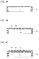
FIG. 4A , thesubstrate 10 is prepared by firing of the laminated body. - Then, a spin coat method or the like is used to coat a photoresist (negative photoresist) onto the
substrate 10 and thereby form a photoresist film. - Then, the photoresist film is patterned by use of photolithography into a shape that corresponds to the first and the second
lower electrodes - Then, a spray coat method or the like is used to coat a catalytic solution containing palladium for example onto openings of the photoresist film.
- Next, as illustrated in
FIG. 4B , after removing the photoresist film, an electroplating method or the like is used to form the first and the secondlower electrodes - Next, a green sheet for the
piezoelectric body 23 is disposed on the first and the secondlower electrodes piezoelectric body 23 may contain Pb3O4 powder or Bi2O3 powder as a sintering auxiliary, a dispersing agent, an organic binder, or the like. - Then, as illustrated in
FIG. 4C , the green sheet for thepiezoelectric body 23 is fired under predetermined conditions (firing temperature 800 degrees C to 1200 degrees C, firing time 0.5 h to 5.0 h) to form thepiezoelectric body 23. However, as used herein, thepiezoelectric body 23 is formed as a single large film-shaped body. - Then, a spin coat method or the like is used to coat a photoresist (positive resist) onto the
piezoelectric body 23 and thereby form a photoresist film R1. - Then, as illustrated in
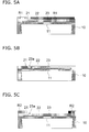
FIG. 5A , the photoresist film R1 is patterned by use of photolithography into a shape that corresponds to the through-hole 23a. - Then, as illustrated in
FIG. 5B , a through-hole 23a is formed by etching thepiezoelectric body 23 by use of an etching liquid for use in relation to the piezoelectric material of thepiezoelectric body 23, and then the photoresist film R1 is removed. The etching liquid may be a mixed liquid of an acidic aqueous solution (for example, 10% concentration of diluted hydrochloric acid), trace amounts of ammonium fluoride, thickening agent, complexing agent, surface active agents, or the like. - In the etching step, the number and size of the recessed
portions 23a and the shape of the through-hole 23a can be adjusted by adjusting the etching conditions. More specifically, the height of the nozzle for discharge of the liquid, the liquid discharge pressure, the oscillation frequency of thesubstrate 10, and the processing time can be controlled to thereby enable adjustment of the interior angle theta, the maximum height roughness Rz and the calculated average roughness Ra of theinner side surface 23U. It is preferred that the calculated average roughness Ra is greater than 0.11 microns and less than 16 microns, the maximum height roughness Rz is greater than 0.2 microns and less than 20 microns, and the interior angle theta is at least 55 degrees and less than or equal to 110 degrees. - Then, a spin coat method or the like is used to coat a photoresist (positive resist) onto the
piezoelectric body 23 and thereby form a photoresist film R2. - Then, as illustrated in
FIG. 5C , the photoresist film R2 is patterned by use of photolithography into a shape that corresponds to theupper electrode 25. - Next as illustrated in
FIG. 6A , a coating method such as a spin coat method or the like is used to coat theelectrode material 25a that contains a conductive material onto the patterned photoresist film R2. Theelectrode material 25a is coated continuously not only onto the surface of thepiezoelectric body 23 but also onto theinner side surface 23U. At this time, as described above, since a suitable roughness is applied to theinner side surface 23U of the through-hole 23a, theelectrode material 25a is maintained in a configuration of covering the whole surface of theinner side surface 23U by filling of theelectrode material 25a into the inner portion of the recessedportions 23a. - Next as illustrated in
FIG. 6B , after removing the photoresist film R2, theelectrode material 25a is fired under predetermined conditions (firing temperature 400 degrees C to 1000 degrees C, firingtime 1 min to 2.0 hr) to form the through-hole electrode 24 and theupper electrode 25. In the firing process, theelectrode material 25a that is filled into the inner portion of the recessedportion 23b moves to the outside of the recessedportion 23b, and thereby enables preparation of a through-hole electrode 24 that is configured with a uniform thin film. - Then, a spin coat method or the like is used to coat a photoresist (positive resist) onto the through-
hole electrode 24 and theupper electrode 25 and thereby form a photoresist film R3. - Then, as illustrated in
FIG. 6C , the photoresist film R3 is patterned by use of photolithography to cover the through-hole electrode 24 and theupper electrode 25. - Next, the
piezoelectric body 23 is etched by an etching liquid for use in relation to a piezoelectric material to thereby pattern thepiezoelectric body 23 as illustrated inFIG. 1 . The etching liquid may be a mixed liquid of an acidic aqueous solution (for example, 10% concentration of diluted hydrochloric acid), trace amounts of ammonium fluoride, a thickening agent, a complexing agent, a surface active agent, or the like. - In this manner, the actuator 100 is completed.
- The calculated average roughness Ra of the
inner side surface 23U of the through-hole 23a is greater than 0.11 microns and less than 16 microns, and the maximum height roughness Rz of theinner side surface 23U of the through-hole 23a is greater than 0.2 microns and less than 20 microns. - Since a suitable roughness is applied to the
inner side surface 23U of the through-hole 23a, the relationship of the surface tension between the electrode material and theinner side surface 23U of theelectrode material 25a is improved, and therefore wetting of theelectrode material 25a is facilitated, and it is possible to inhibit disconnection of the through-hole electrode 24 during drying of theelectrode material 25a. - The technology disclosed herein is not limited to the above embodiments, and includes various modifications or variations within a scope that does not depart from the scope of the present invention.
- For example, in the above embodiment, although a single
upper electrode 25 is formed on the firstmain surface 23S of thepiezoelectric body 23, and two first and secondlower electrodes main surface 23S, the reverse configuration of the electrode structure is also possible. That is to say, two first and second upper electrodes may be formed on the firstmain surface 23S and a single lower electrode may be formed on the secondmain surface 23S. In this configuration, the first upper electrode and the lower electrode may be connected to the through-hole electrode 24. - The examples of the present invention will be described below. However, the present invention is not limited to the examples described below.
- In the following description, inkjet head actuators according to Samples No. 1 to 11 were prepared.
- Firstly, a plurality of green sheets formed by partially stabilized zirconia slurry was laminated to thereby prepare a laminated body having a thickness of 250 microns. Each green sheets was punched into a predetermined pattern to form a cavity (
length 1 mm, width 80 microns, depth 60 microns) corresponding to the pressure chamber and a through hole corresponding to the discharge nozzle in the inner portion of the laminated body. - Next, the substrate was prepared by firing of the laminated body for 2 hours at 1450 degrees C.
- Then, a spin coater was used to coat a negative photoresist liquid onto the surface of the substrate and was dried to thereby form a resist film with a thickness of 6 microns.
- Then, a light shielding liquid that contains carbon black was poured from the discharge nozzle into the pressure chamber and degassing was performed in a vacuum chamber at 6.7 Pa.
- Next, an exposure apparatus (multilight manufactured by Ushio (Inc.)) was used to apply ultraviolet light (integral of light 60 mJ/cm2) having a wavelength of 365 nm, 405 nm and 436 nm from the back surface side of the substrate for one minute. In this manner, the light shielding liquid was used as a mask to expose and pattern the resist film.
- Then, a spray coater was used to coat a catalytic solution containing palladium (manufactured by Uemura & Co. Ltd) onto the opening of the photoresist film.
- Next, after removing the photoresist film, platinum non-electrolytic plating (manufactured by Metalor Technologies Japan) was used to form the lower electrode.
- Next, a slurry containing a plasticizer, a dispersing agent, an organic binder, Pb3O4 and Bi2O3 powder as a sintering auxiliary, and a piezoelectric powder formed from an 0.2Bi(Ni1/3Nb2/3)O3 + 0.8 PZT composition was formed to prepare a green sheet having a thickness of 8 microns.
- Then, the green sheet was adhered onto the lower electrode in a vacuum chamber and a degreasing process was performed.
- Next, the green sheet was fired for two hours at 1000 degrees C to thereby prepare a single film-shaped piezoelectric body (thickness 3 microns).
- Then, a spray coater was used to coat a positive resist liquid (manufactured by Tokyo Ohka Kogyo (Co., Ltd.)) onto the piezoelectric body, and dried.
- Next, a glass mask was used to apply ultraviolet light (integral of light 60 mJ/cm2) having a wavelength of 365 nm, 405 nm and 436 nm for one minute from the surface by use of an exposure apparatus (multilight manufactured by Ushio (Inc.)). In this manner, the resist film is patterned to a shape corresponding to a circular through-hole having a diameter of 30 microns.
- Next, the through-hole was formed according to the conditions shown in Table 1. More specifically, a through-hole was formed in Sample No. 1 and Samples No. 4 to 11 by use of an etching method, and the through-hole in Samples No. 2 and 3 were formed by a blast method. In Sample No. 1 and Samples No. 4 to 11, an etchant was used that was prepared by adding trace amounts of ammonium fluoride, a thickening agent, a complexing agent, and a surface active agent to 10% concentration of diluted hydrochloric acid (fluorine concentration less than 1%). The size of all the through-holes was a circular shape having a diameter of 30 microns.
- In the etching processing step, the interior angle with the surface roughness of the inner side surface of the through-hole was adjusted by controlling the conditions for blasting and the conditions for etching as shown in Table 1. The calculated average roughness Ra, the maximum height roughness Rz and the interior angle theta (refer to
FIG. 3 ) are shown in Table 1. The measurement of the calculated average roughness Ra and the maximum height roughness Rz was performed using a white-light interference non-contact surface roughness meter (manufactured by Canon Inc.: zygo NewView 7300). A cross sectional view of the through-hole was imaged using a scanning electron microscope (acceleration voltage 15 kV) to thereby measure the interior angle theta (θ) by linear fitting using a least squares method to the inner side surface and lower surface on the image. - Then, after patterning the resist film in the same manner as the formation processing step of the lower electrode, a spray coater was used to coat the electrode material onto the piezoelectric body. The electrode material was an Au resinate paste. At this time, the electrode material was coated uniformly to thereby form a connection from the surface of the piezoelectric body to the inner side surface of the through-hole.
- Next, the electrode material was fired for 0.5 hours at 600 degrees C to thereby prepare the upper electrode (width 75 microns, thickness 0.1 micron) and a through-hole electrode.
- Then, a spray coater was used to coat a positive resist liquid (manufactured by Tokyo Ohka Kogyo (Co., Ltd.)) onto the upper electrode, and dried.
- Then a glass mask was used to expose the resist film and thereby form a protective film to cover the upper electrode.
- Next, an etchant was prepared by adding trace amounts of ammonium fluoride, a thickening agent, a complexing agent, and a surface active agent to 10% concentration of diluted hydrochloric acid (fluorine concentration less than 1%), and the etchant and the piezoelectric body are heated to 40 degrees C.
- Then, the etchant was sprayed for two minutes from a nozzle separated by 8 cm from the substrate to thereby etch the piezoelectric body. In this manner, the width of the piezoelectric body was configured to 75 microns. Thereafter, the piezoelectric body was washed in distilled water and dried at 110 degrees C.
- In the through-hole formation processing step described above, the calculated average roughness Ra and the maximum height roughness Rz on the inner side surface of the through-hole in Samples No. 1 to 11 were measured. The measurement of the calculated average roughness Ra and the maximum height roughness Rz was performed using a white-light interference non-contact surface roughness meter (manufactured by Canon Inc.: zygo NewView 7300). The measurement results are shown in Table 1.
- A cross sectional view of the piezoelectric body of Samples No. 1 to 11 was imaged using a scanning electron microscope (acceleration voltage 15 kV) to acquire an SEM image. Linear fitting using a least squares method was applied to the respective inner side surface and lower surface on the SEM image to thereby measure the interior angle theta for both lines. The measurement results are shown in Table 1.
- The presence or absence of a disconnection in the through-hole electrode in Sample No.1 to 11 was confirmed by use of a microscope. The evaluation results are shown in Table 1. In Table 1, a sample in which there is no confirmed disconnection is denoted by ○ and a sample in which there is a confirmed disconnection is denoted by ×.
Table 1 Sample No. Forming Conditions of Through-hole Calculated Average Roughness Ra Maximum Height Roughness Rz Interior Angle θ Disconnection in the Through-hole Electrode Method Height of the nozzle (cm) Discharge Pressure (MPa) Oscillation Frequency of the Substrate (Hz) Time (min) 1 Etching 8 0.1 nothing 2 0.21 0.56 55 ○ 2 Blast 8 0.05 nothing 2 0.07 0.18 55 × 3 Blast 15 0.05 nothing 2 0.06 0.17 45 × 4 Etching 2 0.1 nothing 2 0.32 0.68 110 ○ 5 Etching 1 0.1 nothing 2 0.27 0.77 115 × 6 Etching 16 0.1 nothing 2 16 20 65 ○ 7 Etching 16 0.05 nothing 2 17 20 65 × 8 Etching 8 0.1 1 2 0.11 0.2 55 ○ 9 Etching 8 0.15 1 2 0.1 0.21 60 × 10 Etching 16 0.3 nothing 2 15 25 70 × 11 Etching 8 0.15 1.5 2 0.12 0.19 65 × - As shown in Table 1, no disconnection was confirmed in the through-hole electrode in Samples No. 1, 4, 6 and 8. Therefore, it is shown that it is preferred that the calculated average roughness Ra is larger than 0.11 microns and smaller than 16 microns and that the maximum height roughness Rz is larger than 0.2 microns and smaller than 20 microns. using a white-light interference non-contact surface roughness meter (manufactured by Canon Inc.: zygo NewView 7300). The measurement results are shown in Table 1.
- A cross sectional view of the piezoelectric body of Samples No. 1 to 11 was imaged using a scanning electron microscope (acceleration voltage 15 kV) to acquire an SEM image. Linear fitting using a least squares method was applied to the respective inner side surface and lower surface on the SEM image to thereby measure the interior angle theta for both lines. The measurement results are shown in Table 1.
- The presence or absence of a disconnection in the through-hole electrode in Sample No.1 to 11 was confirmed by use of a microscope. The evaluation results are shown in Table 1. In Table 1, a sample in which there is no confirmed disconnection is denoted by ○ and a sample in which there is a confirmed disconnection is denoted by ×.
Table 1 Sample No. Forming Conditions of Through-hole Calculated Average Roughness Ra Maximum Height Roughness Rz Interior Angle θ Disconnection in the Through-hole Electrode Method Height of the nozzle (cm) Discharge Pressure (MPa) Oscillation Frequency of the Substrate (Hz) Time (min) 1 Etching 8 0.1 nothing 2 0.21 0.56 55 ○ 2 Blast 8 0.05 nothing 2 0.07 0.18 55 × 3 Blast 15 0.05 nothing 2 0.06 0.17 45 × 4 Etching 2 0.1 nothing 2 0.32 0.68 110 ○ 5 Etching 1 0.1 nothing 2 0.27 0.77 115 × 6 Etching 16 0.1 nothing 2 16 20 65 ○ 7 Etching 16 0.05 nothing 2 17 20 65 × 8 Etching 8 0.1 1 2 0.11 0.2 55 ○ 9 Etching 8 0.15 1 2 0.1 0.21 60 × 10 Etching 16 0.3 nothing 2 15 25 70 × 11 Etching 8 0.15 1.5 2 0.12 0.19 65 × - As shown in Table 1, no disconnection was confirmed in the through-hole electrode in Samples No. 1, 4, 6 and 8. Therefore, it is shown that it is preferred that the calculated average roughness Ra is larger than 0.11 microns and smaller than 16 microns and that the maximum height roughness Rz is larger than 0.2 microns and smaller than 20 microns.
- In Sample No. 5, notwithstanding the fact that the calculated average roughness Ra and the maximum height roughness Rz are suitable, a disconnection was confirmed in the through-hole electrode. Therefore, it is shown that it is preferred that the interior angle between the inner side surface and the lower surface is at least 55 degree and less than or equal to 110 degrees. using a white-light interference non-contact surface roughness meter (manufactured by Canon Inc.: zygo NewView 7300). The measurement results are shown in Table 1.
- A cross sectional view of the piezoelectric body of Samples No. 1 to 11 was imaged using a scanning electron microscope (acceleration voltage 15 kV) to acquire an SEM image. Linear fitting using a least squares method was applied to the respective inner side surface and lower surface on the SEM image to thereby measure the interior angle theta for both lines. The measurement results are shown in Table 1.
- The presence or absence of a disconnection in the through-hole electrode in Sample No.1 to 11 was confirmed by use of a microscope. The evaluation results are shown in Table 1. In Table 1, a sample in which there is no confirmed disconnection is denoted by ○ and a sample in which there is a confirmed disconnection is denoted by ×.
Table 1 Sample No. Forming Conditions of Through-hole Calculated Average Roughness Ra Maximum Height Roughness Rz Interior Angle θ Disconnection in the Through-hole Electrode Method Height of the nozzle (cm) Discharge Pressure (MPa) Oscillation Frequency of the Substrate (Hz) Time (min) 1 Etching 8 0.1 nothing 2 0.21 0.56 55 ○ 2 Blast 8 0.05 nothing 2 0.07 0.18 55 × 3 Blast 15 0.05 nothing 2 0.06 0.17 45 × 4 Etching 2 0.1 nothing 2 0.32 0.68 110 ○ 5 Etching 1 0.1 nothing 2 0.27 0.77 115 × 6 Etching 16 0.1 nothing 2 16 20 65 ○ 7 Etching 16 0.05 nothing 2 17 20 65 × 8 Etching 8 0.1 1 2 0.11 0.2 55 ○ 9 Etching 8 0.15 1 2 0.1 0.21 60 × 10 Etching 16 0.3 nothing 2 15 25 70 × 11 Etching 8 0.15 1.5 2 0.12 0.19 65 × - As shown in Table 1, no disconnection was confirmed in the through-hole electrode in Samples No. 1, 4, 6 and 8. Therefore, it is shown that it is preferred that the calculated average roughness Ra is larger than 0.11 microns and smaller than 16 microns and that the maximum height roughness Rz is larger than 0.2 microns and smaller than 20 microns.
- In Sample No. 5, notwithstanding the fact that the calculated average roughness Ra and the maximum height roughness Rz are suitable, a disconnection was confirmed in the through-hole electrode. Therefore, it is shown that it is preferred that the interior angle between the inner side surface and the lower surface is at least 55 degree and less than or equal to 110 degrees.
Claims (4)
- A piezoelectric/electrostrictive element comprising,
a piezoelectric body including a through-hole in communication with a first main surface and a second main surface;
a through-hole electrode formed on an inner side surface of the through-hole;
a first electrode formed on the first main surface of the piezoelectric body, the first electrode connected to the through-hole electrode;
a second electrode formed on the second main surface of the piezoelectric body, the second electrode connected to the through-hole electrode;
a third electrode formed on the second main surface of the piezoelectric body, the third electrode isolated from the second electrode;
a calculated average roughness in the inner side surface being larger than 0.11 microns and smaller than 16 microns; and
a maximum height roughness in the inner side surface being larger than 0.2 microns and smaller than 20 microns. - The piezoelectric/electrostrictive element according to claim 1, wherein
when a sectional surface respectively of the inner side surface and the second main surface is expressed linearly by use of a least squares method, an interior angle formed by the inner side surface and the second main surface is at least 55 degrees and less than or equal to 110 degrees. - The piezoelectric/electrostrictive element according to claim 1 or 2, wherein
a plurality of recessed portions is formed on the inner side surface, and
an inner portion of the respective plurality of recessed portions is configured as a cavity. - A method for manufacturing a piezoelectric/electrostrictive element comprising,
forming a through-hole configured to penetrate a piezoelectric body by use of an etching method; and
coating an electrode material continuously on an inner side surface of the through-hole and a main surface of the piezoelectric body by use of a coating method.
Applications Claiming Priority (1)
| Application Number | Priority Date | Filing Date | Title |
|---|---|---|---|
| JP2013070897A JP6133655B2 (en) | 2013-03-29 | 2013-03-29 | Piezoelectric / electrostrictive element and manufacturing method thereof |
Publications (1)
| Publication Number | Publication Date |
|---|---|
| EP2784836A1 true EP2784836A1 (en) | 2014-10-01 |
Family
ID=50280207
Family Applications (1)
| Application Number | Title | Priority Date | Filing Date |
|---|---|---|---|
| EP20140159739 Withdrawn EP2784836A1 (en) | 2013-03-29 | 2014-03-14 | Piezoelectric/electrostrictive element and method for manufacturing the same |
Country Status (3)
| Country | Link |
|---|---|
| US (1) | US9640749B2 (en) |
| EP (1) | EP2784836A1 (en) |
| JP (1) | JP6133655B2 (en) |
Families Citing this family (7)
| Publication number | Priority date | Publication date | Assignee | Title |
|---|---|---|---|---|
| EP2833424A4 (en) * | 2012-03-30 | 2015-11-11 | Ngk Insulators Ltd | Piezoelectric/electrostrictive film type element and method for producing piezoelectric/electrostrictive film type element |
| EP2833425A4 (en) * | 2012-03-30 | 2015-10-21 | Ngk Insulators Ltd | Piezoelectric/electrostrictive film type element and method for producing piezoelectric/electrostrictive film type element |
| JP6683476B2 (en) * | 2015-12-25 | 2020-04-22 | 日本特殊陶業株式会社 | Piezoelectric element and manufacturing method thereof, foreign matter removing unit, and ultrasonic sensor |
| US11623247B2 (en) * | 2016-02-08 | 2023-04-11 | Konica Minolta, Inc. | Method for producing piezoelectric element, and piezoelectric element |
| CN109801874A (en) * | 2019-01-31 | 2019-05-24 | 绵阳京东方光电科技有限公司 | Via hole structure, manufacturing method thereof, electronic device and display device |
| US12250863B2 (en) | 2019-01-31 | 2025-03-11 | MIANYANG BOE OPTOELECTRONICS TECHNOLOGY CO., Ltd | OLED display panel and OLED display device |
| WO2021053886A1 (en) * | 2019-09-17 | 2021-03-25 | 株式会社村田製作所 | Piezoelectric element |
Citations (4)
| Publication number | Priority date | Publication date | Assignee | Title |
|---|---|---|---|---|
| JP2005051840A (en) * | 2003-07-29 | 2005-02-24 | Kyocera Corp | Method for manufacturing piezoelectric actuator and method for manufacturing print head |
| JP2010050726A (en) * | 2008-08-21 | 2010-03-04 | Murata Mfg Co Ltd | Acoustic wave device and method for manufacturing the same |
| US20110227457A1 (en) * | 2010-02-25 | 2011-09-22 | Nihon Dempa Kogyo Co., Ltd. | Piezoelectric vibrating pieces and devices, and methods for manufacturing same |
| US20110289744A1 (en) * | 2010-05-26 | 2011-12-01 | Ngk Insulators, Ltd. | Method of manufacturing piezoelectric element |
Family Cites Families (8)
| Publication number | Priority date | Publication date | Assignee | Title |
|---|---|---|---|---|
| JP3728623B2 (en) * | 2001-03-02 | 2005-12-21 | 日本碍子株式会社 | Piezoelectric / electrostrictive membrane element |
| US7420317B2 (en) * | 2004-10-15 | 2008-09-02 | Fujifilm Dimatix, Inc. | Forming piezoelectric actuators |
| JP4358087B2 (en) * | 2004-11-22 | 2009-11-04 | Tdk株式会社 | Multilayer ceramic element |
| US7161283B1 (en) * | 2005-06-30 | 2007-01-09 | Avago Technologies Wireless Ip (Singapore) Pte. Ltd. | Method for placing metal contacts underneath FBAR resonators |
| JP2007227872A (en) * | 2006-01-27 | 2007-09-06 | Ngk Insulators Ltd | Piezoelectric / electrostrictive actuator |
| JP5506009B2 (en) * | 2007-02-27 | 2014-05-28 | キヤノン株式会社 | Piezoelectric element, method for manufacturing the same, diaphragm, and vibration wave drive device |
| JP2009005143A (en) * | 2007-06-22 | 2009-01-08 | Ngk Insulators Ltd | Piezoelectric thin film device |
| US7768178B2 (en) * | 2007-07-27 | 2010-08-03 | Fujifilm Corporation | Piezoelectric device, piezoelectric actuator, and liquid discharge device having piezoelectric films |
-
2013
- 2013-03-29 JP JP2013070897A patent/JP6133655B2/en not_active Expired - Fee Related
-
2014
- 2014-02-26 US US14/190,586 patent/US9640749B2/en not_active Expired - Fee Related
- 2014-03-14 EP EP20140159739 patent/EP2784836A1/en not_active Withdrawn
Patent Citations (4)
| Publication number | Priority date | Publication date | Assignee | Title |
|---|---|---|---|---|
| JP2005051840A (en) * | 2003-07-29 | 2005-02-24 | Kyocera Corp | Method for manufacturing piezoelectric actuator and method for manufacturing print head |
| JP2010050726A (en) * | 2008-08-21 | 2010-03-04 | Murata Mfg Co Ltd | Acoustic wave device and method for manufacturing the same |
| US20110227457A1 (en) * | 2010-02-25 | 2011-09-22 | Nihon Dempa Kogyo Co., Ltd. | Piezoelectric vibrating pieces and devices, and methods for manufacturing same |
| US20110289744A1 (en) * | 2010-05-26 | 2011-12-01 | Ngk Insulators, Ltd. | Method of manufacturing piezoelectric element |
Non-Patent Citations (2)
| Title |
|---|
| EZHILVALAVAN S ET AL: "Ferroelectric properties of wet-chemical patterned PbZr0.52Ti0.48O3 films", APPLIED PHYSICS LETTERS, AMERICAN INSTITUTE OF PHYSICS, US, vol. 86, no. 7, 7 February 2005 (2005-02-07), pages 72901 - 072901, XP012066376, ISSN: 0003-6951, DOI: 10.1063/1.1864234 * |
| XIAO-HUI XU ET AL: "Preparation of a high-quality PZT thick film with performance comparable to those of bulk materials for applications in MEMS; Preparation of a high-quality PZT thick film with performance comparable to those of bulk materials", JOURNAL OF MICROMECHANICS & MICROENGINEERING, INSTITUTE OF PHYSICS PUBLISHING, BRISTOL, GB, vol. 18, no. 6, 1 June 2008 (2008-06-01), pages 65001, XP020136879, ISSN: 0960-1317 * |
Also Published As
| Publication number | Publication date |
|---|---|
| JP2014195002A (en) | 2014-10-09 |
| US9640749B2 (en) | 2017-05-02 |
| US20140292159A1 (en) | 2014-10-02 |
| JP6133655B2 (en) | 2017-05-24 |
Similar Documents
| Publication | Publication Date | Title |
|---|---|---|
| US9640749B2 (en) | Piezoelectric/electrostrictive element and method for manufacturing the same | |
| US7882607B2 (en) | Method of manufacturing an actuator device | |
| KR19990070321A (en) | Micro Actuator Manufacturing Method | |
| JP4386924B2 (en) | Method for forming piezoelectric actuator of inkjet head | |
| US20140091678A1 (en) | Laminate | |
| JP4737375B2 (en) | Method for manufacturing actuator device, method for manufacturing liquid jet head, and method for manufacturing liquid jet device | |
| US7497962B2 (en) | Method of manufacturing liquid discharge head and method of manufacturing substrate for liquid discharge head | |
| US9484519B2 (en) | Piezoelectric/electrostrictive element | |
| US8727508B2 (en) | Bonded silicon structure for high density print head | |
| US10513118B2 (en) | Methods of producing electromechanical transducer, sensor, and actuator | |
| JP3280349B2 (en) | Microactuator and ink jet printer head using the same | |
| JP3582475B2 (en) | Piezoelectric / electrostrictive film type element | |
| JP6081449B2 (en) | Piezoelectric / electrostrictive membrane element and method for manufacturing piezoelectric / electrostrictive membrane element | |
| CN1408550A (en) | Piezoelectric inkjet print head and manufacturing method thereof | |
| WO2013146975A1 (en) | Piezoelectric/electrostrictive film type element and method for producing piezoelectric/electrostrictive film type element | |
| US7343654B2 (en) | Method of manufacturing a piezoelectric element and a liquid ink jet head | |
| CN1408548A (en) | Piezoelectric inkjet print head and manufacturing method thereof | |
| JP2005219243A (en) | Method for manufacturing liquid jet head and liquid jet head | |
| KR100717487B1 (en) | Sputtering target, method for producing sputtering target, sputtering apparatus, and liquid-jet head | |
| KR100374589B1 (en) | Micro actuator and inkjet printer head manufactured using the same | |
| JP2012124210A (en) | Method of manufacturing piezoelectric module and method of manufacturing piezoelectric device | |
| JP2001130011A (en) | Ink jet head, method of manufacturing the same, and ink jet recording apparatus | |
| JP2006144090A (en) | Sputtering method, sputtering apparatus, piezoelectric element manufacturing method, and liquid jet head | |
| JP2007173605A (en) | Method for manufacturing piezoelectric element and method for manufacturing liquid jet head | |
| KR20090003889A (en) | Method of manufacturing piezo actuator |
Legal Events
| Date | Code | Title | Description |
|---|---|---|---|
| 17P | Request for examination filed |
Effective date: 20140314 |
|
| AK | Designated contracting states |
Kind code of ref document: A1 Designated state(s): AL AT BE BG CH CY CZ DE DK EE ES FI FR GB GR HR HU IE IS IT LI LT LU LV MC MK MT NL NO PL PT RO RS SE SI SK SM TR |
|
| AX | Request for extension of the european patent |
Extension state: BA ME |
|
| PUAI | Public reference made under article 153(3) epc to a published international application that has entered the european phase |
Free format text: ORIGINAL CODE: 0009012 |
|
| R17P | Request for examination filed (corrected) |
Effective date: 20150401 |
|
| RBV | Designated contracting states (corrected) |
Designated state(s): AL AT BE BG CH CY CZ DE DK EE ES FI FR GB GR HR HU IE IS IT LI LT LU LV MC MK MT NL NO PL PT RO RS SE SI SK SM TR |
|
| 17Q | First examination report despatched |
Effective date: 20150806 |
|
| GRAP | Despatch of communication of intention to grant a patent |
Free format text: ORIGINAL CODE: EPIDOSNIGR1 |
|
| INTG | Intention to grant announced |
Effective date: 20160125 |
|
| STAA | Information on the status of an ep patent application or granted ep patent |
Free format text: STATUS: THE APPLICATION IS DEEMED TO BE WITHDRAWN |
|
| 18D | Application deemed to be withdrawn |
Effective date: 20160607 |