EP2784651A2 - Transmitter with rotating knob - Google Patents
Transmitter with rotating knob Download PDFInfo
- Publication number
- EP2784651A2 EP2784651A2 EP14161622.7A EP14161622A EP2784651A2 EP 2784651 A2 EP2784651 A2 EP 2784651A2 EP 14161622 A EP14161622 A EP 14161622A EP 2784651 A2 EP2784651 A2 EP 2784651A2
- Authority
- EP
- European Patent Office
- Prior art keywords
- setting
- display portion
- transmitter
- operation button
- value
- Prior art date
- Legal status (The legal status is an assumption and is not a legal conclusion. Google has not performed a legal analysis and makes no representation as to the accuracy of the status listed.)
- Granted
Links
Images




Classifications
-
- G—PHYSICS
- G05—CONTROLLING; REGULATING
- G05B—CONTROL OR REGULATING SYSTEMS IN GENERAL; FUNCTIONAL ELEMENTS OF SUCH SYSTEMS; MONITORING OR TESTING ARRANGEMENTS FOR SUCH SYSTEMS OR ELEMENTS
- G05B15/00—Systems controlled by a computer
- G05B15/02—Systems controlled by a computer electric
-
- G—PHYSICS
- G06—COMPUTING OR CALCULATING; COUNTING
- G06F—ELECTRIC DIGITAL DATA PROCESSING
- G06F3/00—Input arrangements for transferring data to be processed into a form capable of being handled by the computer; Output arrangements for transferring data from processing unit to output unit, e.g. interface arrangements
- G06F3/01—Input arrangements or combined input and output arrangements for interaction between user and computer
- G06F3/03—Arrangements for converting the position or the displacement of a member into a coded form
- G06F3/033—Pointing devices displaced or positioned by the user, e.g. mice, trackballs, pens or joysticks; Accessories therefor
- G06F3/0362—Pointing devices displaced or positioned by the user, e.g. mice, trackballs, pens or joysticks; Accessories therefor with detection of one-dimensional [1D] translations or rotations of an operating part of the device, e.g. scroll wheels, sliders, knobs, rollers or belts
-
- G—PHYSICS
- G06—COMPUTING OR CALCULATING; COUNTING
- G06F—ELECTRIC DIGITAL DATA PROCESSING
- G06F3/00—Input arrangements for transferring data to be processed into a form capable of being handled by the computer; Output arrangements for transferring data from processing unit to output unit, e.g. interface arrangements
- G06F3/01—Input arrangements or combined input and output arrangements for interaction between user and computer
- G06F3/048—Interaction techniques based on graphical user interfaces [GUI]
- G06F3/0481—Interaction techniques based on graphical user interfaces [GUI] based on specific properties of the displayed interaction object or a metaphor-based environment, e.g. interaction with desktop elements like windows or icons, or assisted by a cursor's changing behaviour or appearance
- G06F3/0482—Interaction with lists of selectable items, e.g. menus
-
- G—PHYSICS
- G06—COMPUTING OR CALCULATING; COUNTING
- G06F—ELECTRIC DIGITAL DATA PROCESSING
- G06F3/00—Input arrangements for transferring data to be processed into a form capable of being handled by the computer; Output arrangements for transferring data from processing unit to output unit, e.g. interface arrangements
- G06F3/01—Input arrangements or combined input and output arrangements for interaction between user and computer
- G06F3/048—Interaction techniques based on graphical user interfaces [GUI]
- G06F3/0484—Interaction techniques based on graphical user interfaces [GUI] for the control of specific functions or operations, e.g. selecting or manipulating an object, an image or a displayed text element, setting a parameter value or selecting a range
- G06F3/04847—Interaction techniques to control parameter settings, e.g. interaction with sliders or dials
-
- G—PHYSICS
- G06—COMPUTING OR CALCULATING; COUNTING
- G06F—ELECTRIC DIGITAL DATA PROCESSING
- G06F3/00—Input arrangements for transferring data to be processed into a form capable of being handled by the computer; Output arrangements for transferring data from processing unit to output unit, e.g. interface arrangements
- G06F3/01—Input arrangements or combined input and output arrangements for interaction between user and computer
- G06F3/048—Interaction techniques based on graphical user interfaces [GUI]
- G06F3/0487—Interaction techniques based on graphical user interfaces [GUI] using specific features provided by the input device, e.g. functions controlled by the rotation of a mouse with dual sensing arrangements, or of the nature of the input device, e.g. tap gestures based on pressure sensed by a digitiser
Definitions
- the present disclosure relates to a transmitter. Particularly, the present disclosure relates to improvement in inputting and setting attribute information of the transmitter.
- various measured physical amounts such as pressures, temperatures, flow rates, etc. in respective portions of a process piping system are converted into electric signals and the electric signals are transmitted to an instrument panel room.
- various transmitters are used for the respective portions of the process piping system.
- operation portions are provided so that attribute information unique to the transmitters can be inputted and set by the transmitters alone without use of any other tools in installation sites upon initial setting, maintenance and inspection work during plant operation, device replacement work, etc.
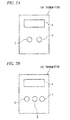
- Figs. 7A and 7B are views of conceptual examples of related-art transmitters 101 and 102.
- the transmitter 101 shown in Fig. 7A two operation buttons 2 and 3 for operating switches are provided under a display portion 1.
- the transmitter 102 shown in Fig. 7B three operation buttons 5 to 7 are provided under a display portion 4.
- a function of selecting one from setting items and one from setting values is assigned to the operation button 2
- a function of determining the setting item and the setting value which have been switched and selected by the operation button 2 is assigned to the operation button 3.
- the character string of the setting item can be switched sequentially and cyclically, for example, from “address” back to “address” via "calibration", “unit”, “damping", “display”, “identification” and “end”.
- the character string of the setting item is switched and displayed on the display portion 1 sequentially in connection with the pushing-down operation of the operation button 2.
- the setting item selected by the operation button 2 at that point of time is determined as a subject whose setting value will be changed.
- the mode is changed over to a change mode in which the setting value of the determined setting item can be switched from one to another in a predetermined direction (for example, in an ascending direction).
- the setting value in the setting item is switched and displayed on the display portion 1 sequentially in connection with the pushing-down operation of the operation button 2.
- the operation button 3 is pushed down in the state in which the setting value switched to a desired one has been displayed by the pushing-down operation of the operation button 2.
- the value selected thus is determined as the setting value of the setting item selected and determined by the operation button 2, and inputted to a not-shown signal processor.
- the operation button 2 is pushed down to select a numerical value for each digit and the operation button 3 is then pushed down to shift the current digit to a next digit.
- a function of selecting one from setting items is assigned to the operation button 5
- a function of selecting one from setting values in an ascending direction is assigned to the operation button 6
- a function of selecting one from the setting values in a descending direction is assigned to the operation button 7.
- the setting item can be switched sequentially and cyclically, for example, from “address” back to “address” via "calibration", “unit”, “damping”, “display”, “identification” and “end” in the same manner as in Fig. 7A .
- the setting item is switched and displayed on the display portion 4 sequentially in connection with the pushing-down operation of the operation button 5.
- the setting value in the setting item can be switched and selected from one to another.
- the operation button 5 When the operation button 5 is pushed down in the state in which the setting value switched to a desired one has been selected and displayed by the operation button 6 or the operation button 7, the value selected thus is determined as the setting value and inputted to a not-shown signal processor.
- the operation button 6 or the operation button 7 is pushed down to change only the numerical value in the least significant digit to thereby change numerical values in higher-order digits (the tenth place and the hundredth place).
- JP-A-2013-030349 A technique for performing setting by means of a plurality of infrared switches has been described in JP-A-2013-030349 .
- the operation button 2 can be operated to change the setting value from one to another sequentially only in one predetermined direction. Accordingly, once the setting value exceeds a desired setting value by only one, the setting value cannot be moved back, but the operation button 2 has to be operated again from the start after passing the remaining alternatives.
- the operating amount of the operation button 2 and the operation button 3 for selecting numerical values of a numerical string differs from the operating amount of the operation button 2 and the operation button 3 for selecting a character string. That is, as to the character string of the setting item, a desired character string can be selected simply by pushing down the operation button 2. In the case where the numerical values of the numerical string are set, it is necessary to operate the operation button 2 to select a desired numerical value for each digit and to operate the operation button 3 to shift the current digit to a next digit.
- Fig. 7B two operation buttons, i.e. the operation button 6 and the operation button 7, are required for switching and selecting a setting value in the ascending direction and the descending direction. Accordingly, the same function for switching and selecting a setting value cannot be integrated into one operation button. As a result, the number of components increases.
- the ascending direction and the descending direction for switching the setting value are assigned to the two operation buttons 6 and 7 respectively.
- the setting value is switched and selected in either the ascending direction or the descending direction by the same pushing-down operation of the operation button 6 or the operation button 7. Therefore, the operation is not intuitive.
- a transmitter includes: a display portion, wherein setting items for the transmitter and setting values of the setting items are displayed on the display portion; an first input receiver configured to receive a first selecting operation for selecting one of the setting items and a second selecting operation for selecting one of the setting values; a second input receiver configured to receive a switching operation for sequentially switching the setting values of the setting item which is selected by the first selecting operation in response to a rotation direction of the second input receiver; and a first controller configured to display the setting values of the selected setting item on the display portion such that the setting values are sequentially switched in response to the switching operation received by the second input receiver.
- the second input receiver is configured to be rotated in a first rotation direction or in a second rotation direction opposite to the first rotation direction.
- the first controller is configured to: i) display the setting values of the selected setting item on the display portion such that the setting values are sequentially switched in a forward direction when the second input receiver is rotated in the first rotation direction by the switching operation; and ii) display the setting values of the selected setting item on the display portion such that the setting values are sequentially switched in a backward direction when the second input receiver is rotated in the second rotation direction by the switching operation.
- the first input receiver is configured as a button
- the second input receiver is configured as a screw
- the forward direction is a direction for increasing the setting value displayed on the display portion
- the backward direction is a direction for decreasing the setting value displayed on the display portion
- the first controller is configured to determine a change amount of switching of the setting values in response to a rotation speed of the second input receiver when the second input receiver is rotated by the switching operation.
- the first input receiver and the second input receiver are integrated with each other.
- the transmitter further comprises a second controller configured to display the setting items on the display portion such that the setting items are sequentially switched and configured to determine one of the setting values when the first input receiver receives the second selecting operation.
- Fig. 1 is a conceptual view of a transmitter 100 according to an embodiment of the invention.
- one operation button 9 serving as a first input receiver for operating a not-shown switch from the outside is provided under a display portion 8 and one screw 10 serving as a second input receiver for performing zero adjustment from the outside is provided under the operation button 9.
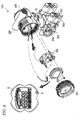
- Fig. 8 is a schematic view of the transmitter 100 according to the embodiment of the invention.
- other mechanical elements as well as the display portion 8, the operation button 9 and a screw 10 shown in Fig. 1 are shown as the mechanical configuration of transmitter 100.
- an amplifier cover 201, a mounting screw 202, a CPU assembly 203, a vent plug 204, a drain plug 205, a process connector 206, a process connection 207, an external indicator conduit connection 208 and a conduit connection 209 are shown in Fig. 8 , respectively.
- Fig. 2 is a block diagram showing an internal configuration of the transmitter 100 shown in Fig. 1 .
- the internal functions are implemented based on operations of the operation button 9 and the screw 10 in Fig. 1 .
- a contact signal of the switch changing in connection with a pushing-down operation of the operation button 9 is detected by an operation detector 11 and inputted to a selection controller 12.
- the selection controller 12 executes two operations.
- a character string of a setting item stored in a setting item character string storage unit 13 is read sequentially based on the contact signal of the switch issued in connection with the pushing-down operation of the operation button 9 detected by the operation detector 11 before a rotation operation of the screw 10, so that the setting item can be switched and displayed on the display portion 8.
- a setting value changed to increase/decrease by the rotation operation of the screw 10 is determined based on the contact signal of the switch issued in connection with the pushing-down operation of the operation button 9 detected by the operation detector 11.
- the selected character string of the setting item is inputted to the display portion 8, a selection controller 15 and a setting item calculation processor 16.
- a rotational motion based on the rotation operation of the screw 10 is transmitted to an operation detector 14 which is, for example, constituted by a known rotary encoder, so that the rotation direction and the rotation speed can be detected.
- the detected rotation direction and the detected rotation speed are inputted to the selection controller 15.
- the selection controller 15 informs the selection controller 12 of the fact that the rotation operation has started. Then, the selection controller 15 inputs a rotation operation signal to the setting item calculation processor 16.
- the setting item calculation processor 16 performs predetermined calculation processing based on a setting value which has been changed to increase/decrease by the screw 10 and determined by the operation button 9. Then, the setting item calculation processor 16 outputs a result of the calculation to the display portion 8 and a setting value storage unit 17. The setting value stored in the setting value storage unit 17 is read out by the setting item calculation processor 16.
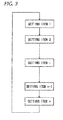
- Fig. 3 is a view showing an example of transition of a display state on the display portion 8 shown in Fig. 2 .
- the display portion 8 displays a setting item 1 in an initial state.
- the operation button 9 is pushed down once in this state
- the setting item displayed on the display portion 8 is switched to a setting item 2.
- the operation button 9 is pushed down once, in the same manner, the setting item displayed on the display portion 8 is switched to a next setting item sequentially.
- the setting item displayed on the display portion 8 is switched to a setting item n via a setting time i, one cycle is completed and then the setting item 1 as the initial state will be next displayed again. In this manner, a unidirectional cycle is repeated.
- FIG. 3 A specific example of Fig. 3 will be described. For example, assume that there are three setting items as follows. In this case, the transition of display on the display portion 8 will be made as shown in Fig. 4 .
- setting values which can be set in the setting items include discrete values (Identification Numbers, Addresses) and continuous values (zero points).
- the normal display on the display portion 8 is the Process Value 18.
- the zero point of the Process Value 18 can be changed to increase/decrease.
- the operation button 9 When the operation button 9 is pushed down once in the state in which the Process Value 18 is displayed, the display on the display portion 8 is switched to the Identification Number 19.
- the Identification Number can be changed.
- the operation button 9 When the operation button 9 is pushed down once after the screw 10 is rotated, the changed Identification Number is determined.
- the operation button 9 When the operation button 9 is pushed down once in the state in which the Identification Number 19 is displayed, the display on the display portion 8 is switched to the Address 20.
- the Address can be changed.
- the operation button 9 When the operation button 9 is pushed down once after the screw 10 is rotated, the changed Address is determined.
- the display on the display portion 8 is switched synchronously with the switching of the internal processes. That is, when the internal process of the Process Value 18 is selected, the Process Value 18 is displayed. When the internal process of the Identification Number 19 is selected, the Identification Number 19 is displayed. When the internal process of the Address 20 is selected, the Address 20 is displayed.
- integer values are assigned separately as labels. For example, 0 is assigned to the Process Value 18, 1 is assigned to the Identification Number 19 and 2 is assigned to the Address 20.
- integer values of the labels assigned as described above are used to select one from the internal processes. For example, when the integer value 0 is selected, the internal process of the Process Value 18 is selected. When the integer value 1 is selected, the internal process of the Identification Number 19 is selected. When the integer value 2 is selected, the internal process of the Address 20 is selected.
- the integer value of the label is incremented by 1. For example, when the operation button 9 is pushed down once in the state in which the integer value is 0, the integer value is incremented to 1. When the operation button 9 is pushed down once in the state in which the integer value is 1, the integer value is incremented to 2. When the operation button 9 is pushed down once in the state in which the integer value is 2, the integer value is incremented to 3. However, when the operation button 9 is pushed down once in the state in which the integer value is 2, there is no internal process assigned. Therefore, the integer value is returned to 0.
- the internal process selected currently is specified based on the integer value of the label.
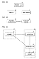
- Fig. 5B is a view of state transition of the internal process of the Process Value 18 shown in Fig. 5A .
- the initial transition destination is pressure calculation 21. Acquired pressure is calculated in the pressure calculation 21.
- an adjustment amount 22 corresponding to the operating amount of the screw 10 is reflected on the pressure calculation 21.
- the state of the internal process of the process value 18 transits to the pressure calculation 21.
- the adjustment amount 22 is automatically reflected on the pressure calculation 21 displayed on the display portion 8. Whenever the screw 10 is operated, the adjustment amount 22 is automatically reflected on the pressure calculation 21 not as the display on the display portion 8 but as setting of internal data.
- the adjustment amount is a positive real number when the screw 10 is rotated clockwise.
- the adjustment amount is a negative real number when the screw 10 is rotated counterclockwise.
- Fig. 5C is a view of state transition of the Identification Number 19 and the Address 20 shown in Fig. 5A .
- the initial transition destination is standby 23.
- the transmitter waits for two inputs deriving from the pushing-down operation of the operation button 9 and the operation of the screw 10.
- a desired value is selected in the selection 24.
- the value selected in the selection 24 is reflected as a setting value on the internal data.
- the transmitter is restarted in the restart 26.
- Each internal process is constituted by two stages, i.e. non-edition time 27 and edition time 28.
- the non-edition time 27 contains the standby 23.
- the edition time 28 contains the selection 24, the determination 25 and the restart 26.
- Transition between the non-edition time 27 and the edition time 28 has only the following three systems. Without transition from the non-edition time 27 to the edition time 28, the processing of the selection 24, the determination 25 and the restart 26 is not executed.
- Fig. 6 is an explanatory view showing the relationship between combination of validation/invalidation of the aforementioned “LOCAL_OP_ENABLE” and “WRITE_LOCK” and setting operation.
- the continuous value and the adjustment amount 22 are real-number values and the number of rotations of the screw 10 is an integer value.
- the following change rates are assigned respectively based on the numbers of rotations of the screw 10 detected in a certain period of time.
- the adjustment amount 22 is a value calculated based on these change rates.
- the change rate is so small that fine adjustment can be performed.
- the change rate is so large that rough adjustment can be performed.
- the discrete value, each alternative of the selection 24 and the number of rotations of the screw 10 are all integer values.
- the following change amounts are assigned respectively based on the numbers of rotations of the screw 10 detected in a certain period of time.
- the change amount is added to an integer value which is the alternative indicated before the screw 10 is operated, and the integer value obtained thus is set as a new alterative.
- the Identification Number in the Identification Number 19 can be set in a range of integer values 0 to 8.
- the integer values are assigned as labels separately and respectively to the following character strings displayed on the display portion 8.
- the integer values calculated as described above are set as integer values assigned to the character strings, that is, labels respectively.
- the calculated integer value is 4, "9702" to which the integer value 4 is assigned is selected as the Identification Number.
- the integer value calculated as described above is out of the range, the integer value is corrected.
- cyclical selection of the Identification Number can be implemented.
- the calculated integer value is -1
- the integer value is corrected to 8 so that "AUTO" is selected as the Identification Number.
- the integer value is corrected to 0 so that "4580" is selected as the Identification Number.
- the Address in the Address 20 can be set within a range of integer values 0 to 125.
- the integer value calculated as described above is set as the value of the selected Address.
- the calculated integer value is 54, 54 is selected as the Address.
- the integer value calculated as described above is out of the range, the integer value is corrected. By this correction, cyclical selection of the Address is implemented.
- the calculated integer value is -6, 120 is selected as the Address.
- the calculated integer value is 134, 8 is selected as the Address.
- the button may be arranged as a non-contact type such as a magnetic type or an optical type.
- Basic setting items may include not only items for communication setting but also items for general setting such as upper limits, lower limits and damping values.
- fine adjustment/rough adjustment may be implemented in accordance with the operating amount of the screw.
- the screw used in the invention is not used for fastening and fixation but serves for rotation operation.
- the button and the switch or the button and the screw do not need to be configured independently.
- the button and the switch or the button and the screw may be formed as an integral type such as a winding crown of a watch.
- configuration may be made so that the rotation motion based on the rotation operation of the screw can be detected as a rotation angle.
- Configuration may be made so that the changeover operation based on the button can be performed based on physical movement of a rotary or sliding operation button etc.
- a switch for performing changeover between validation and invalidation of a simulation mode or a switch for performing changeover between validation and invalidation of "WRITE_LOCK" may be also arranged so that the switch can be operated on the operation button from the outside in the same manner as the switch for performing changeover among display operations of the display portion.
- a switch for performing changeover between validation and invalidation of an integration function, between validation and invalidation of "LOCAL_OP_ENABLE", between validation and invalidation of a diagnosis function, among transmitter gauge kinds (an absolute pressure gauge, a pressure gauge and a differential pressure gauge), etc. may be arranged so that the switch can be operated on the operation button from the outside.
- a screw which can be operated from the outside in order to adjust the zero point of a measurement signal is used in the embodiment
- a screw which can, for example, select a communication type, set receiver (pressure receiver) sensitivity, perform changeover between pressure reception directions (High side and Low side) in accordance with reverse connection of process piping, set a preset value of an integration function, or set a collection cycle of an abnormality history, etc. may be arranged so that the switch can be operated from the outside.
- the operation function may be switched from one to another in accordance with the operating amount of the operation button such as the operation time thereof or the number of times of operation thereof per unit time.
- the button when the button is pushed down for a short time, the button can serve as an "internal process switching" function or a "setting value selection” function.
- the operation button When the button is pushed down for a long time, the operation button can serve as a "setting value determination" function.
Landscapes
- Engineering & Computer Science (AREA)
- General Engineering & Computer Science (AREA)
- Theoretical Computer Science (AREA)
- Physics & Mathematics (AREA)
- General Physics & Mathematics (AREA)
- Human Computer Interaction (AREA)
- Automation & Control Theory (AREA)
- Selective Calling Equipment (AREA)
- Measuring Fluid Pressure (AREA)
- Arrangements For Transmission Of Measured Signals (AREA)
- Input From Keyboards Or The Like (AREA)
Abstract
Description
- The present disclosure relates to a transmitter. Particularly, the present disclosure relates to improvement in inputting and setting attribute information of the transmitter.
- In a process control system, various measured physical amounts such as pressures, temperatures, flow rates, etc. in respective portions of a process piping system are converted into electric signals and the electric signals are transmitted to an instrument panel room. To this end, various transmitters are used for the respective portions of the process piping system.
- In some of the transmitters, operation portions are provided so that attribute information unique to the transmitters can be inputted and set by the transmitters alone without use of any other tools in installation sites upon initial setting, maintenance and inspection work during plant operation, device replacement work, etc.
-
Figs. 7A and 7B are views of conceptual examples of related-art transmitters transmitter 101 shown inFig. 7A , twooperation buttons display portion 1. In thetransmitter 102 shown inFig. 7B , threeoperation buttons 5 to 7 are provided under a display portion 4. - In the
transmitter 101 shown inFig. 7A , for example, a function of selecting one from setting items and one from setting values is assigned to theoperation button 2, and a function of determining the setting item and the setting value which have been switched and selected by theoperation button 2 is assigned to theoperation button 3. - When the
operation button 2 is pushed down intermittently, the character string of the setting item can be switched sequentially and cyclically, for example, from "address" back to "address" via "calibration", "unit", "damping", "display", "identification" and "end". The character string of the setting item is switched and displayed on thedisplay portion 1 sequentially in connection with the pushing-down operation of theoperation button 2. - When the
operation button 3 is pushed down, the setting item selected by theoperation button 2 at that point of time is determined as a subject whose setting value will be changed. Thus, the mode is changed over to a change mode in which the setting value of the determined setting item can be switched from one to another in a predetermined direction (for example, in an ascending direction). Then, the setting value in the setting item is switched and displayed on thedisplay portion 1 sequentially in connection with the pushing-down operation of theoperation button 2. - Assume that the
operation button 3 is pushed down in the state in which the setting value switched to a desired one has been displayed by the pushing-down operation of theoperation button 2. In this case, the value selected thus is determined as the setting value of the setting item selected and determined by theoperation button 2, and inputted to a not-shown signal processor. - In the case where a numerical string is inputted and set as the setting value, the
operation button 2 is pushed down to select a numerical value for each digit and theoperation button 3 is then pushed down to shift the current digit to a next digit. - In the
transmitter 102 as shown inFig. 7B , for example, a function of selecting one from setting items is assigned to theoperation button 5, a function of selecting one from setting values in an ascending direction is assigned to theoperation button 6 and a function of selecting one from the setting values in a descending direction is assigned to theoperation button 7. - When the
operation button 5 is pushed down intermittently, the setting item can be switched sequentially and cyclically, for example, from "address" back to "address" via "calibration", "unit", "damping", "display", "identification" and "end" in the same manner as inFig. 7A . The setting item is switched and displayed on the display portion 4 sequentially in connection with the pushing-down operation of theoperation button 5. - When the
operation button 6 or theoperation button 7 is pushed down in the state in which a desired setting item has been displayed on the display portion 4, the setting value in the setting item can be switched and selected from one to another. - When the
operation button 5 is pushed down in the state in which the setting value switched to a desired one has been selected and displayed by theoperation button 6 or theoperation button 7, the value selected thus is determined as the setting value and inputted to a not-shown signal processor. - In the case where a numerical string is inputted and set as the setting value, the
operation button 6 or theoperation button 7 is pushed down to change only the numerical value in the least significant digit to thereby change numerical values in higher-order digits (the tenth place and the hundredth place). - A technique for performing setting by means of a plurality of infrared switches has been described in
JP-A-2013-030349 - According to the configuration of
Fig. 7A , theoperation button 2 can be operated to change the setting value from one to another sequentially only in one predetermined direction. Accordingly, once the setting value exceeds a desired setting value by only one, the setting value cannot be moved back, but theoperation button 2 has to be operated again from the start after passing the remaining alternatives. - Assume that, for example, it is desired to select the seventh alternative from ten alternatives. In this case, when the seventh alternative is missed and switched to the eighth alternative and the eighth alternative is displayed, the seventh option cannot be displayed again immediately. It is therefore necessary to operate the
operation button 2 for one cycle from 8 to 7 via 9, 10, 1, ...6. In order to restart from the start in this manner, extra man-hours are required to deteriorate the operability. - In addition, the operating amount of the
operation button 2 and theoperation button 3 for selecting numerical values of a numerical string differs from the operating amount of theoperation button 2 and theoperation button 3 for selecting a character string. That is, as to the character string of the setting item, a desired character string can be selected simply by pushing down theoperation button 2. In the case where the numerical values of the numerical string are set, it is necessary to operate theoperation button 2 to select a desired numerical value for each digit and to operate theoperation button 3 to shift the current digit to a next digit. - On the other hand, according to the configuration of
Fig. 7B , two operation buttons, i.e. theoperation button 6 and theoperation button 7, are required for switching and selecting a setting value in the ascending direction and the descending direction. Accordingly, the same function for switching and selecting a setting value cannot be integrated into one operation button. As a result, the number of components increases. - In addition, the ascending direction and the descending direction for switching the setting value are assigned to the two
operation buttons operation button 6 or theoperation button 7. Therefore, the operation is not intuitive. - It is an object of the present invention to provide a transmitter which has a comparatively simple configuration and in which a setting value can be switched in ascending and descending directions intuitively by a common operation and both a numerical string and a character string can be switched.
- According to a first aspect of the present invention, there is provided a transmitter. The transmitter includes: a display portion, wherein setting items for the transmitter and setting values of the setting items are displayed on the display portion; an first input receiver configured to receive a first selecting operation for selecting one of the setting items and a second selecting operation for selecting one of the setting values; a second input receiver configured to receive a switching operation for sequentially switching the setting values of the setting item which is selected by the first selecting operation in response to a rotation direction of the second input receiver; and a first controller configured to display the setting values of the selected setting item on the display portion such that the setting values are sequentially switched in response to the switching operation received by the second input receiver.
- According to a second aspect of the present invention, the second input receiver is configured to be rotated in a first rotation direction or in a second rotation direction opposite to the first rotation direction. The first controller is configured to: i) display the setting values of the selected setting item on the display portion such that the setting values are sequentially switched in a forward direction when the second input receiver is rotated in the first rotation direction by the switching operation; and ii) display the setting values of the selected setting item on the display portion such that the setting values are sequentially switched in a backward direction when the second input receiver is rotated in the second rotation direction by the switching operation.
- According to a third aspect of the present invention, the first input receiver is configured as a button, and the second input receiver is configured as a screw.
- According to a fourth aspect of the present invention, the forward direction is a direction for increasing the setting value displayed on the display portion, and the backward direction is a direction for decreasing the setting value displayed on the display portion.
- According to a fourth aspect of the present invention, the first controller is configured to determine a change amount of switching of the setting values in response to a rotation speed of the second input receiver when the second input receiver is rotated by the switching operation.
- According to a sixth aspect of the present invention, the first input receiver and the second input receiver are integrated with each other.
- According to a seventh aspect of the present invention, the transmitter further comprises a second controller configured to display the setting items on the display portion such that the setting items are sequentially switched and configured to determine one of the setting values when the first input receiver receives the second selecting operation.
-
-
Fig. 1 is a conceptual view showing a portion of a transmitter according to an embodiment of the invention; -
Fig. 2 is a block diagram showing an internal configuration of the transmitter shown inFig. 1 ; -
Fig. 3 is a view showing an example of transition of a display state on adisplay portion 8 shown inFig. 2 ; -
Fig. 4 is a view showing a specific example of the transition of the display state inFig. 3 ; -
Figs. 5A to 5C are explanatory views explaining internal processes of three setting items; -
Fig. 6 is an explanatory view showing the relation between combination of validation/invalidation of "LOCAL_OP_ENABLE" and "WRITE_LOCK" and setting operation; -
Fig. 7A and 7B are views of conceptual examples of related-art transmitters; and -
Fig. 8 is a schematic view of the transmitter according to the embodiment of the invention, wherein other mechanical elements as well as adisplay portion 8, anoperation button 9 and ascrew 10 shown inFig. 1 are shown in the transmitter shown inFig. 8 . -
Fig. 1 is a conceptual view of atransmitter 100 according to an embodiment of the invention. InFig. 1 , oneoperation button 9 serving as a first input receiver for operating a not-shown switch from the outside is provided under adisplay portion 8 and onescrew 10 serving as a second input receiver for performing zero adjustment from the outside is provided under theoperation button 9. -
Fig. 8 is a schematic view of thetransmitter 100 according to the embodiment of the invention. InFig. 8 , other mechanical elements as well as thedisplay portion 8, theoperation button 9 and ascrew 10 shown inFig. 1 are shown as the mechanical configuration oftransmitter 100. As other mechanical elements of thetransmitter 100, anamplifier cover 201, a mountingscrew 202, aCPU assembly 203, avent plug 204, adrain plug 205, aprocess connector 206, aprocess connection 207, an externalindicator conduit connection 208 and aconduit connection 209 are shown inFig. 8 , respectively. -
Fig. 2 is a block diagram showing an internal configuration of thetransmitter 100 shown inFig. 1 . The internal functions are implemented based on operations of theoperation button 9 and thescrew 10 inFig. 1 . A contact signal of the switch changing in connection with a pushing-down operation of theoperation button 9 is detected by anoperation detector 11 and inputted to aselection controller 12. - The
selection controller 12 executes two operations. In the first operation, a character string of a setting item stored in a setting item characterstring storage unit 13 is read sequentially based on the contact signal of the switch issued in connection with the pushing-down operation of theoperation button 9 detected by theoperation detector 11 before a rotation operation of thescrew 10, so that the setting item can be switched and displayed on thedisplay portion 8. - In the second operation, which is executed after a rotation operation of the
screw 10, a setting value changed to increase/decrease by the rotation operation of thescrew 10 is determined based on the contact signal of the switch issued in connection with the pushing-down operation of theoperation button 9 detected by theoperation detector 11. The selected character string of the setting item is inputted to thedisplay portion 8, aselection controller 15 and a settingitem calculation processor 16. - A rotational motion based on the rotation operation of the
screw 10 is transmitted to anoperation detector 14 which is, for example, constituted by a known rotary encoder, so that the rotation direction and the rotation speed can be detected. The detected rotation direction and the detected rotation speed are inputted to theselection controller 15. - As soon as the rotation operation of the
screw 10 starts, theselection controller 15 informs theselection controller 12 of the fact that the rotation operation has started. Then, theselection controller 15 inputs a rotation operation signal to the settingitem calculation processor 16. - On the setting item selected by the
operation button 9, the settingitem calculation processor 16 performs predetermined calculation processing based on a setting value which has been changed to increase/decrease by thescrew 10 and determined by theoperation button 9. Then, the settingitem calculation processor 16 outputs a result of the calculation to thedisplay portion 8 and a settingvalue storage unit 17. The setting value stored in the settingvalue storage unit 17 is read out by the settingitem calculation processor 16. -
Fig. 3 is a view showing an example of transition of a display state on thedisplay portion 8 shown inFig. 2 . Thedisplay portion 8 displays asetting item 1 in an initial state. When theoperation button 9 is pushed down once in this state, the setting item displayed on thedisplay portion 8 is switched to asetting item 2. Whenever theoperation button 9 is pushed down once, in the same manner, the setting item displayed on thedisplay portion 8 is switched to a next setting item sequentially. When the setting item displayed on thedisplay portion 8 is switched to a setting item n via a setting time i, one cycle is completed and then thesetting item 1 as the initial state will be next displayed again. In this manner, a unidirectional cycle is repeated. - Description will be made on a setting value determination operation, for example, in the state in which the
operation button 9 has been pushed down once to switch the setting item to the setting item i. - 1) When the
screw 10 is rotated, a predetermined setting value corresponding to the setting item i is changed to increase/decrease. - 2) When the
operation button 9 is pushed down once in the state in which the setting value has been changed to increase/decrease to a desired setting value, the setting value is determined as the changed setting value. - 3) When the
operation button 9 is pushed down once, the setting item is switched to a setting item (i + 1). - A specific example of
Fig. 3 will be described. For example, assume that there are three setting items as follows. In this case, the transition of display on thedisplay portion 8 will be made as shown inFig. 4 . - a)
Process Value 18, which is for zero adjustment - b)
Identification Number 19, which is one piece of information necessary for PROFIBUS communication and used for identifying a device to communicate with - c)
Address 20, which is a setting of Bus Address and which is one piece of information generally necessary for communication and used for designating a device to communicate with - Incidentally, setting values which can be set in the setting items include discrete values (Identification Numbers, Addresses) and continuous values (zero points).
- The normal display on the
display portion 8 is theProcess Value 18. When thescrew 10 is rotated in the state in which the Process Value is displayed, the zero point of theProcess Value 18 can be changed to increase/decrease. - When the
operation button 9 is pushed down once in the state in which theProcess Value 18 is displayed, the display on thedisplay portion 8 is switched to theIdentification Number 19. When thescrew 10 is rotated in the state in which theIdentification Number 19 is displayed, the Identification Number can be changed. When theoperation button 9 is pushed down once after thescrew 10 is rotated, the changed Identification Number is determined. - When the
operation button 9 is pushed down once in the state in which theIdentification Number 19 is displayed, the display on thedisplay portion 8 is switched to theAddress 20. When thescrew 10 is rotated in the state in which theAddress 20 is displayed, the Address can be changed. When theoperation button 9 is pushed down once after thescrew 10 is rotated, the changed Address is determined. - When the
operation button 9 is pushed down once in the state in which theAddress 20 is displayed, the display on thedisplay portion 8 is returned to the normal display state to indicate theProcess value 18. - Internal processes of the three setting items consisting of the
Process Value 18, theIdentification Number 19 and theAddress 20 will be described. As shown inFig. 5A , these three setting items in the internal processes are independent of one another and closed to have no relevance to one another. That is, the process of theProcess Value 18 does not affect the processes of theIdentification Number 19 and theAddress 20. The process of theIdentification Number 19 does not affect the processes of theAddress 20 and theProcess Value 18. The process of theAddress 20 does not affect the processes of theProcess Value 18 and theIdentification Number 19. - The display on the
display portion 8 is switched synchronously with the switching of the internal processes. That is, when the internal process of theProcess Value 18 is selected, theProcess Value 18 is displayed. When the internal process of theIdentification Number 19 is selected, theIdentification Number 19 is displayed. When the internal process of theAddress 20 is selected, theAddress 20 is displayed. - During the internal processes, integer values are assigned separately as labels. For example, 0 is assigned to the
Process Value Identification Number Address 20. - The integer values of the labels assigned as described above are used to select one from the internal processes. For example, when the integer value 0 is selected, the internal process of the
Process Value 18 is selected. When theinteger value 1 is selected, the internal process of theIdentification Number 19 is selected. When theinteger value 2 is selected, the internal process of theAddress 20 is selected. - When the
operation button 9 is pushed down once in the state in which an internal process has been selected using an integer value of a label, the integer value of the label is incremented by 1. For example, when theoperation button 9 is pushed down once in the state in which the integer value is 0, the integer value is incremented to 1. When theoperation button 9 is pushed down once in the state in which the integer value is 1, the integer value is incremented to 2. When theoperation button 9 is pushed down once in the state in which the integer value is 2, the integer value is incremented to 3. However, when theoperation button 9 is pushed down once in the state in which the integer value is 2, there is no internal process assigned. Therefore, the integer value is returned to 0. - In addition, the internal process selected currently is specified based on the integer value of the label.
-
Fig. 5B is a view of state transition of the internal process of theProcess Value 18 shown inFig. 5A . The initial transition destination ispressure calculation 21. Acquired pressure is calculated in thepressure calculation 21. When thescrew 10 is operated in thepressure calculation 21, anadjustment amount 22 corresponding to the operating amount of thescrew 10 is reflected on thepressure calculation 21. When thescrew 10 is not operated, the state of the internal process of theprocess value 18 transits to thepressure calculation 21. - The
adjustment amount 22 is automatically reflected on thepressure calculation 21 displayed on thedisplay portion 8. Whenever thescrew 10 is operated, theadjustment amount 22 is automatically reflected on thepressure calculation 21 not as the display on thedisplay portion 8 but as setting of internal data. - For example, the adjustment amount is a positive real number when the
screw 10 is rotated clockwise. The adjustment amount is a negative real number when thescrew 10 is rotated counterclockwise. -
Fig. 5C is a view of state transition of theIdentification Number 19 and theAddress 20 shown inFig. 5A . - The state transition will be described first.
- The initial transition destination is
standby 23. In the state of thestandby 23, the transmitter waits for two inputs deriving from the pushing-down operation of theoperation button 9 and the operation of thescrew 10. - Transition starting from the
standby 23 will be made as follows. - 1) To transit to the
standby 23 as long as theoperation button 9 is not pushed down and thescrew 10 is not operated. - 2) To terminate the current setting item and transit to a next setting item when the
operation button 9 is pushed down. - 3) To transit to
selection 24 when thescrew 10 is operated. - A desired value is selected in the
selection 24. - 1) A desired Identification Number is selected from alternatives in the
Identification Number 19. - 2) A desired Address is selected from alternatives in the
Address 20. - Transition starting from the
selection 24 will be made as follows. - 1) To transit to the
selection 24 as long as theoperation button 9 is not pushed down. - 2) To make it possible to select an alternative in a forward/backward direction when the
screw 10 is operated. - 3) To make selection, for example, in the forward direction when the
screw 10 is rotated clockwise and in the backward direction when thescrew 10 is rotated counterclockwise. - 4) To transit to
determination 25 when theoperation button 9 is pushed down. - In the
determination 25, the value selected in theselection 24 is reflected as a setting value on the internal data. - Transition starting from the
determination 25 will be made as follows. - 1) To transit to restart 26 when a restart process is necessary after the reflection of the setting value on the internal data.
- 2) To transit to the
restart 26 in theAddress 20 after the reflection of the setting value on the internal data. - 3) To transit to the
standby 23 when a restart process is not necessary after the reflection of the setting value on the internal data. - 4) To transit to the
standby 23 in theIdentification Number 19 after the reflection of the setting value on the internal data. - The transmitter is restarted in the
restart 26. - Next, management of the state transition will be described.
- Each internal process is constituted by two stages, i.e. non-edition
time 27 andedition time 28. - The
non-edition time 27 contains thestandby 23. Theedition time 28 contains theselection 24, thedetermination 25 and therestart 26. - Transition between the
non-edition time 27 and theedition time 28 has only the following three systems. Without transition from thenon-edition time 27 to theedition time 28, the processing of theselection 24, thedetermination 25 and therestart 26 is not executed. - 1) from
Standby 23 toSelection 24 - 2) from
Determination 25 toStandby 23 - Next, measures to prevent erroneous setting will be described. A not-shown setting tool is used to invalidate a function of "LOCAL_OP_ENABLE". Thus, operation of the button and operation of the screw are invalidated collectively. Description will be made on operations in the case where the
operation button 9 is pushed down in the condition that the function of "LOCAL_OP _ENABLE" is invalidated and in the case where thescrew 10 is operated likewise. - Operations in the case where the
transmitter 100 is in thestandby 23 will be performed as follows. - 1) Not to accept any operating amount even if the
operation button 9 is pushed down. - 2) To display on the display portion 8 a message "FAILED" indicating that the operation is disabled.
- 3) To transit to the
Process Value 18 after "FAILED" is displayed. - Operations in the case where the
transmitter 100 is in theselection 24 will be performed as follows. - 1) Not to accept any operating amount even if the
operation button 9 is pushed down. - 2) To display on the display portion 8 a message "FAILED" indicating that the operation is disabled.
- 3) To invalidate operation in the
selection 24 but not to transit to thedetermination 25. - 4) To transit to the
standby 23 - 5) To transit to the
Process Value 18 after the transition to thestandby 23. - Operations in the case where the
transmitter 100 is in thestandby 23 will be performed as follows. - 1) Not to accept any operating amount even if the
screw 10 is operated. - 2) To display on the display portion 8 a message "FAILED" indicating that the operation is disabled.
- 3) Not to transit to the
selection 24. - 4) To transit to the
standby 23. - Operations in the case where the
transmitter 100 is in theselection 24 will be performed as follows. - 1) Not to accept any operating amount even if the
screw 10 is operated. - 2) To display on the display portion 8 a message "FAILED" meaning that the operation is disabled.
- 3) To invalidate operation in the
selection 24. - 4) To transit to the
standby 23. - When the not-shown setting tool is used to validate a function of "WRITE_LOCK", a write operation is invalidated. However, an exception occurs in zero adjustment, in which the write operation is validated. On this occasion, a message (key mark) meaning that setting is disabled is displayed on the display portion. Description will be made on operations in the case where the
operation button 9 is pushed down in the condition that the function of "WRITE_LOCK" is validated and in the case where thescrew 10 is operated likewise. - An operation in the case where the
transmitter 100 is in thestandby 23 will be performed as follows. - 1) To switch to a next internal process.
- Operations in the case where the
transmitter 100 is in theselection 24 will be performed as follows. - 1) Not to accept any operating amount even if the
operation button 9 is pushed down. - 2) To display on the display portion 8 a message "FAILED" indicating that the operation is disabled.
- 3) To invalidate operation in the
selection 24 but not to transit to thedetermination 25. - 4) To transit to the
standby 23. - Operations in the case where the
transmitter 100 is in thestandby 23 will be performed as follows. - 1) Not to accept any operating amount even if the
screw 10 is operated. - 2) To display on the display portion 8 a message "FAILED" indicating that the operation is disabled.
- 3) Not to transit to the
selection 24. - 4) To transit to the
standby 23. - Operations in the case where the
transmitter 100 is in theselection 24 will be performed as follows. - 1) Not to accept any operating amount even if the
screw 10 is operated. - 2) To display on the display portion 8 a message "FAILED" indicating that the operation is disabled.
- 3) To invalidate operation in the
selection 24. - 4) To transit to the
standby 23. - The case where a write operation can be executed will be described.
- There are two conditions to transit to the
determination 25 as follows. - 1) "LOCAL_OP_ENABLE" is validated.
- 2) "WRITE_LOCK" is invalidated.
- After transition to the
determination 25 and completion of reflection on the internal data, a message "SAVED" indicating that the write operation has been completed is displayed on thedisplay portion 8. - In the case where the value selected in the
selection 24 is the same as the previous value in spite of transition to thedetermination 25, the following operations will be performed. - 1) Not to reflect on the internal data.
- 2) Not to display "SAVED".
- These operations are used as cancellation of the write operation.
-
Fig. 6 is an explanatory view showing the relationship between combination of validation/invalidation of the aforementioned "LOCAL_OP_ENABLE" and "WRITE_LOCK" and setting operation. - a) "LOCAL_OP_ENABLE" validated and "WRITE_LOCK" invalidated, operation enabled and setting enabled
(The setting value can be either confirmed using theoperation button 9 and set using thescrew 10.) - b) "LOCAL_OP_ENABLE" validated and "WRITE_LOCK" validated, operation enabled and setting disabled
(The setting value can be confirmed using theoperation button 9 but cannot be set using thescrew 10. However, an exception occurs in zero adjustment, in which setting can be done using thescrew 10.) - c) "LOCAL_OP_ENABLE" invalidated and "WRITE_LOCK" invalidated, operation disabled and setting enabled
(The setting value cannot be either confirmed using theoperation button 9 or set using thescrew 10.) - d) "LOCAL_OP_ENABLE" invalidated and "WRITE_LOCK" validated, operation disabled and setting disabled
(The setting value cannot be either confirmed using theoperation button 9 or set using thescrew 10.) - The operating amount of the
screw 10 in the case where a continuous value is selected inFig. 5B will be described. - The continuous value and the
adjustment amount 22 are real-number values and the number of rotations of thescrew 10 is an integer value. For example, the following change rates are assigned respectively based on the numbers of rotations of thescrew 10 detected in a certain period of time. -
- 1) When the number of rotations is 0, the change rate corresponds to 0.00%.
- 2) When the number of rotations is 1, the change rate corresponds to 0.01 %.
- 3) When the number of rotations is 2, the change rate corresponds to 0.03%.
- 4) When the number of rotations is 3, the change rate corresponds to 0.40%.
- 5) When the number of rotations is 4, the change rate corresponds to 1.50%.
- 6) When the number of rotations is 5, the change rate corresponds to 4.00%.
- 7) When the number of rotations is 6, the change rate corresponds to 10.00%.
- 8) When the number of rotations is 7 or more, the change rate corresponds to 10.00%.
- The
adjustment amount 22 is a value calculated based on these change rates. When the number of rotations is small, the change rate is so small that fine adjustment can be performed. When the number of rotations is large, the change rate is so large that rough adjustment can be performed. - The operating amount of the
screw 10 in the case where a discrete value is selected inFig. 5C will be described. - The discrete value, each alternative of the
selection 24 and the number of rotations of thescrew 10 are all integer values. The following change amounts are assigned respectively based on the numbers of rotations of thescrew 10 detected in a certain period of time. -
- 1) When the number of rotations is 0, the change amount corresponds to 0.
- 2) When the number of rotations is 1, the change amount corresponds to 1.
- 3) When the number of rotations is 2 or more, the change amount corresponds to 1.
-
- 1) When the number of rotations is 0, the change amount corresponds to 0.
- 2) When the number of rotations is 1, the change amount corresponds to 1.
- 3) When the number of rotations is 2, the change amount corresponds to 10.
- 4) When the number of rotations is 3 or more, the change amount corresponds to 10.
- The change amount is added to an integer value which is the alternative indicated before the
screw 10 is operated, and the integer value obtained thus is set as a new alterative. - Correspondence between integer values and character strings displayed on the
display portion 8 will be described. - The Identification Number in the
Identification Number 19 can be set in a range of integer values 0 to 8. The integer values are assigned as labels separately and respectively to the following character strings displayed on thedisplay portion 8. - 1) "4580" corresponds to 0
- 2) "4581" corresponds to 1
- 3) "9700" corresponds to 2
- 4) "9701" corresponds to 3
- 5) "9702" corresponds to 4
- 6) "9740" corresponds to 5
- 7) "9741" corresponds to 6
- 8) "9742" corresponds to 7
- 9) "AUTO" corresponds to 8
- The integer values calculated as described above are set as integer values assigned to the character strings, that is, labels respectively. When, for example, the calculated integer value is 4, "9702" to which the integer value 4 is assigned is selected as the Identification Number.
- When the integer value calculated as described above is out of the range, the integer value is corrected. By this correction, cyclical selection of the Identification Number can be implemented. When, for example, the calculated integer value is -1, the integer value is corrected to 8 so that "AUTO" is selected as the Identification Number. When, for example, the calculated integer value is 9, the integer value is corrected to 0 so that "4580" is selected as the Identification Number.
- The Address in the
Address 20 can be set within a range of integer values 0 to 125. The integer value calculated as described above is set as the value of the selected Address. When, for example, the calculated integer value is 54, 54 is selected as the Address. - When the integer value calculated as described above is out of the range, the integer value is corrected. By this correction, cyclical selection of the Address is implemented. When, for example, the calculated integer value is -6, 120 is selected as the Address. When, for example, the calculated integer value is 134, 8 is selected as the Address.
- In this manner, basic setting for establishing communication can be carried out simply by operation of the
button 9 and thescrew 10 in thetransmitter 100 alone so that current setting information can be grasped simply by operation of the button and the screw in the transmitter alone. Thus, a dedicated device, a coupler, a terminator, etc. used for setting can be dispensed with. It may go well as long as a power supply for driving the transmitter is provided. - Incidentally, the button may be arranged as a non-contact type such as a magnetic type or an optical type.
- Basic setting items may include not only items for communication setting but also items for general setting such as upper limits, lower limits and damping values.
- "Digit selection" using the button and "setting for each digit" using the screw may be made for setting a numerical string or a character string.
- In addition, fine adjustment/rough adjustment may be implemented in accordance with the operating amount of the screw. Incidentally, the screw used in the invention is not used for fastening and fixation but serves for rotation operation.
- In addition, the button and the switch or the button and the screw do not need to be configured independently. For example, the button and the switch or the button and the screw may be formed as an integral type such as a winding crown of a watch.
- In addition, configuration may be made so that the rotation motion based on the rotation operation of the screw can be detected as a rotation angle.
- Configuration may be made so that the changeover operation based on the button can be performed based on physical movement of a rotary or sliding operation button etc.
- In addition, although the embodiment has been described along an example where a switch which can be operated from the outside for performing changeover among display operations of the display portion is operated on the button, a switch for performing changeover between validation and invalidation of a simulation mode or a switch for performing changeover between validation and invalidation of "WRITE_LOCK" may be also arranged so that the switch can be operated on the operation button from the outside in the same manner as the switch for performing changeover among display operations of the display portion.
- Further, for example, a switch for performing changeover between validation and invalidation of an integration function, between validation and invalidation of "LOCAL_OP_ENABLE", between validation and invalidation of a diagnosis function, among transmitter gauge kinds (an absolute pressure gauge, a pressure gauge and a differential pressure gauge), etc. may be arranged so that the switch can be operated on the operation button from the outside.
- In addition, although a screw which can be operated from the outside in order to adjust the zero point of a measurement signal is used in the embodiment, a screw which can, for example, select a communication type, set receiver (pressure receiver) sensitivity, perform changeover between pressure reception directions (High side and Low side) in accordance with reverse connection of process piping, set a preset value of an integration function, or set a collection cycle of an abnormality history, etc. may be arranged so that the switch can be operated from the outside.
- Incidentally, the operation function may be switched from one to another in accordance with the operating amount of the operation button such as the operation time thereof or the number of times of operation thereof per unit time. For example, when the button is pushed down for a short time, the button can serve as an "internal process switching" function or a "setting value selection" function. When the button is pushed down for a long time, the operation button can serve as a "setting value determination" function.
- While certain embodiments have been described, these embodiments have been presented by way of example only, and are not intended to limit the scope of the invention. Indeed, the novel methods and systems described herein may be embodied in a variety of other forms. Furthermore, various omissions, substitutions and changes in the form of the methods and systems described herein may be made without departing from the sprit of the invention. The accompanying claims and their equivalents are intended to cover such forms or modifications as would fall within the scope and sprit of the invention.
Claims (7)
- A transmitter (100), comprising:a display portion (8), wherein setting items for the transmitter and setting values of the setting items are displayed on the display portion (8);an first input receiver (9) configured to receive a first selecting operation for selecting one of the setting items and a second selecting operation for selecting one of the setting values;a second input receiver (10) configured to receive a switching operation for sequentially switching the setting values of the setting item which is selected by the first selecting operation in response to a rotation direction of the second input receiver; anda first controller (15) configured to display the setting values of the selected setting item on the display portion (8) such that the setting values are sequentially switched in response to the switching operation received by the second input receiver (10).
- Transmitter of claim 1, wherein the second input receiver is configured to be rotated in a first rotation direction or in a second rotation direction opposite to the first rotation direction, and
wherein the first controller (15) is configured to:i) display the setting values of the selected setting item on the display portion (8) such that the setting values are sequentially switched in a forward direction when the second input receiver (10) is rotated in the first rotation direction by the switching operation; andii) display the setting values of the selected setting item on the display portion (8) such that the setting values are sequentially switched in a backward direction when the second input receiver (10) is rotated in the second rotation direction by the switching operation. - The transmitter of claim 1 or 2, wherein the first input receiver (9) is configured as a button, and the second input receiver (10) is configured as a screw.
- The transmitter of claim 2, wherein the forward direction is a direction for increasing the setting value displayed on the display portion (8), and the backward direction is a direction for decreasing the setting value displayed on the display portion (8).
- The transmitter of claim 1 or 2, wherein the first controller (15) is configured to determine a change amount of switching of the setting values in response to a rotation speed of the second input receiver (10) when the second input receiver is rotated by the switching operation.
- The transmitter of claim 1 or 2, wherein the first input receiver (9) and the second input receiver (10) are integrated with each other.
- The transmitter of claim 1 or 2, further comprising:a second controller (12) configured to display the setting items on the display portion (8) such that the setting items are sequentially switched and configured to determine one of the setting values when the first input receiver (9) receives the second selecting operation.
Applications Claiming Priority (1)
| Application Number | Priority Date | Filing Date | Title |
|---|---|---|---|
| JP2013063685A JP5862900B2 (en) | 2013-03-26 | 2013-03-26 | Transmitter |
Publications (3)
| Publication Number | Publication Date |
|---|---|
| EP2784651A2 true EP2784651A2 (en) | 2014-10-01 |
| EP2784651A3 EP2784651A3 (en) | 2015-03-25 |
| EP2784651B1 EP2784651B1 (en) | 2019-09-18 |
Family
ID=50513019
Family Applications (1)
| Application Number | Title | Priority Date | Filing Date |
|---|---|---|---|
| EP14161622.7A Active EP2784651B1 (en) | 2013-03-26 | 2014-03-25 | Transmitter with rotating knob |
Country Status (4)
| Country | Link |
|---|---|
| US (1) | US9996063B2 (en) |
| EP (1) | EP2784651B1 (en) |
| JP (1) | JP5862900B2 (en) |
| CN (1) | CN104076764B (en) |
Cited By (1)
| Publication number | Priority date | Publication date | Assignee | Title |
|---|---|---|---|---|
| DE102018129437B3 (en) | 2018-11-22 | 2020-04-23 | Krohne Messtechnik Gmbh | Transmitter and field device |
Citations (1)
| Publication number | Priority date | Publication date | Assignee | Title |
|---|---|---|---|---|
| JP2013030349A (en) | 2011-07-28 | 2013-02-07 | Yokogawa Electric Corp | Infrared switch and operation state display method of infrared switch |
Family Cites Families (22)
| Publication number | Priority date | Publication date | Assignee | Title |
|---|---|---|---|---|
| JPH01232130A (en) * | 1988-03-09 | 1989-09-18 | Kawasaki Heavy Ind Ltd | Control display device for work machine with engine |
| JP2951718B2 (en) * | 1990-11-28 | 1999-09-20 | 東京エレクトロン株式会社 | Zero adjustment device for pressure gauge output |
| JP3377673B2 (en) * | 1996-03-07 | 2003-02-17 | 株式会社日立製作所 | Inverter device |
| JPH109989A (en) * | 1996-06-21 | 1998-01-16 | Hitachi Ltd | Digital pressure gauge |
| JP2000231689A (en) * | 1999-02-12 | 2000-08-22 | Saginomiya Seisakusho Inc | Physical quantity transmitter, physical quantity condition monitoring system, and pressure monitoring device for gas for electrical insulation |
| US20020132617A1 (en) * | 2001-01-05 | 2002-09-19 | Nuss Randall S. | Method and apparatus for providing virtual frequency identifiers for internet radio |
| JP2002323372A (en) * | 2001-04-27 | 2002-11-08 | Minolta Co Ltd | Exposure meter |
| JP2004021893A (en) | 2002-06-20 | 2004-01-22 | Sony Corp | Portable information communication terminal, program, and recording medium recording the program |
| JP2004264248A (en) * | 2003-03-04 | 2004-09-24 | Sanyo Electric Co Ltd | Electronic digital pressure switch |
| US20070132733A1 (en) * | 2004-06-08 | 2007-06-14 | Pranil Ram | Computer Apparatus with added functionality |
| ATE425487T1 (en) | 2004-09-15 | 2009-03-15 | Harman Becker Automotive Sys | MULTIMEDIA SYSTEM FOR VEHICLES AND METHOD FOR OPERATING A MULTIMEDIA SYSTEM FOR VEHICLES |
| JP2006292702A (en) * | 2005-03-18 | 2006-10-26 | Sunx Ltd | Detection sensor |
| JP2006284251A (en) * | 2005-03-31 | 2006-10-19 | Sunx Ltd | Detection sensor and liquid detection sensor |
| US8564543B2 (en) * | 2006-09-11 | 2013-10-22 | Apple Inc. | Media player with imaged based browsing |
| US8268261B2 (en) * | 2006-11-22 | 2012-09-18 | Altair Corporation | Pipette core member, pipette, and pipette device |
| US20080154576A1 (en) * | 2006-12-21 | 2008-06-26 | Jianchao Wu | Processing of reduced-set user input text with selected one of multiple vocabularies and resolution modalities |
| CN101271360A (en) * | 2007-03-23 | 2008-09-24 | 英群企业股份有限公司 | Input device, electronic device using the same and input method thereof |
| US20100096018A1 (en) * | 2008-02-27 | 2010-04-22 | Wylie Jacob E | Instant hot water delivery system |
| CN101729674A (en) * | 2009-12-17 | 2010-06-09 | 中兴通讯股份有限公司 | Operating method for interactive processing of mobile office and video call and mobile terminal |
| JP5652650B2 (en) * | 2010-11-15 | 2015-01-14 | 横河電機株式会社 | Differential pressure transmitter |
| JP5818474B2 (en) * | 2011-03-23 | 2015-11-18 | 新コスモス電機株式会社 | Indicator |
| US10073537B2 (en) * | 2012-03-12 | 2018-09-11 | Samsung Electronics Co., Ltd. | User interface device and electronic apparatus having the same |
-
2013
- 2013-03-26 JP JP2013063685A patent/JP5862900B2/en active Active
-
2014
- 2014-03-21 US US14/221,787 patent/US9996063B2/en active Active
- 2014-03-25 EP EP14161622.7A patent/EP2784651B1/en active Active
- 2014-03-26 CN CN201410116178.2A patent/CN104076764B/en active Active
Patent Citations (1)
| Publication number | Priority date | Publication date | Assignee | Title |
|---|---|---|---|---|
| JP2013030349A (en) | 2011-07-28 | 2013-02-07 | Yokogawa Electric Corp | Infrared switch and operation state display method of infrared switch |
Cited By (3)
| Publication number | Priority date | Publication date | Assignee | Title |
|---|---|---|---|---|
| DE102018129437B3 (en) | 2018-11-22 | 2020-04-23 | Krohne Messtechnik Gmbh | Transmitter and field device |
| EP3657137A1 (en) | 2018-11-22 | 2020-05-27 | Krohne Messtechnik GmbH | Transmitter and field device |
| CN111210605A (en) * | 2018-11-22 | 2020-05-29 | 克洛纳测量技术有限公司 | Transmitter and field device |
Also Published As
| Publication number | Publication date |
|---|---|
| CN104076764A (en) | 2014-10-01 |
| US9996063B2 (en) | 2018-06-12 |
| JP2014190715A (en) | 2014-10-06 |
| CN104076764B (en) | 2017-01-11 |
| US20140297046A1 (en) | 2014-10-02 |
| EP2784651A3 (en) | 2015-03-25 |
| EP2784651B1 (en) | 2019-09-18 |
| JP5862900B2 (en) | 2016-02-16 |
Similar Documents
| Publication | Publication Date | Title |
|---|---|---|
| US10036659B2 (en) | Method for function setting of a measuring point and measuring point | |
| US9520157B2 (en) | Storage modes for measurement values and contextual information | |
| JP2000513798A (en) | Analog spectrum display device for environmental control | |
| CN102095340A (en) | Display configuration for multimode electronic calipers having a ratiometric measurement mode | |
| US11175819B2 (en) | Virtual functional modules for measuring devices and equipment components | |
| JPWO2023190234A5 (en) | ||
| CN107030527B (en) | Remote display device for metering in personal area network | |
| CN210833912U (en) | Temperature monitoring instrument and system capable of realizing automatic temperature calibration | |
| US9996063B2 (en) | Transmitter | |
| US20130186965A1 (en) | Integrated temperature and humidity control device | |
| KR20130084329A (en) | Display device, and method for verifying operation of display device | |
| US20170176226A1 (en) | Multi-mode metrology user interface device | |
| JP6798461B2 (en) | Notification control device, notification control system, notification control method, and notification control program | |
| US5220499A (en) | Electronic measuring apparatus having general purpose processing unit | |
| US20130169446A1 (en) | Device for displaying rotation speed of fan | |
| GB2321328A (en) | Transmitting and receiving remote controller pointing data | |
| JP2019128911A (en) | Processing time prediction device | |
| US12045447B2 (en) | Method for extending the operating functionality of a field device in the field of automation technology from one operating device to at least one other operating device | |
| CN111776190B (en) | A digital rudder angle feedback indication system and control method | |
| US7222049B2 (en) | User-viewable relative diagnostic output | |
| KR200432487Y1 (en) | Wireless transceiver for measuring instruments | |
| CN109443397A (en) | Motor positioning precision testing device and method | |
| RU234625U1 (en) | Data acquisition device for calibration of measuring instruments | |
| CN103984257A (en) | Signal conversion method and system | |
| CN119225339A (en) | Detection method, device, equipment and medium for distributed control system |
Legal Events
| Date | Code | Title | Description |
|---|---|---|---|
| 17P | Request for examination filed |
Effective date: 20140325 |
|
| AK | Designated contracting states |
Kind code of ref document: A2 Designated state(s): AL AT BE BG CH CY CZ DE DK EE ES FI FR GB GR HR HU IE IS IT LI LT LU LV MC MK MT NL NO PL PT RO RS SE SI SK SM TR |
|
| AX | Request for extension of the european patent |
Extension state: BA ME |
|
| PUAI | Public reference made under article 153(3) epc to a published international application that has entered the european phase |
Free format text: ORIGINAL CODE: 0009012 |
|
| PUAL | Search report despatched |
Free format text: ORIGINAL CODE: 0009013 |
|
| AK | Designated contracting states |
Kind code of ref document: A3 Designated state(s): AL AT BE BG CH CY CZ DE DK EE ES FI FR GB GR HR HU IE IS IT LI LT LU LV MC MK MT NL NO PL PT RO RS SE SI SK SM TR |
|
| AX | Request for extension of the european patent |
Extension state: BA ME |
|
| RIC1 | Information provided on ipc code assigned before grant |
Ipc: G06F 3/0487 20130101AFI20150216BHEP Ipc: G06F 3/0362 20130101ALI20150216BHEP Ipc: G06F 3/0484 20130101ALI20150216BHEP Ipc: G06F 3/0482 20130101ALI20150216BHEP |
|
| R17P | Request for examination filed (corrected) |
Effective date: 20150901 |
|
| RBV | Designated contracting states (corrected) |
Designated state(s): AL AT BE BG CH CY CZ DE DK EE ES FI FR GB GR HR HU IE IS IT LI LT LU LV MC MK MT NL NO PL PT RO RS SE SI SK SM TR |
|
| STAA | Information on the status of an ep patent application or granted ep patent |
Free format text: STATUS: EXAMINATION IS IN PROGRESS |
|
| 17Q | First examination report despatched |
Effective date: 20180119 |
|
| GRAP | Despatch of communication of intention to grant a patent |
Free format text: ORIGINAL CODE: EPIDOSNIGR1 |
|
| STAA | Information on the status of an ep patent application or granted ep patent |
Free format text: STATUS: GRANT OF PATENT IS INTENDED |
|
| INTG | Intention to grant announced |
Effective date: 20190327 |
|
| GRAS | Grant fee paid |
Free format text: ORIGINAL CODE: EPIDOSNIGR3 |
|
| GRAA | (expected) grant |
Free format text: ORIGINAL CODE: 0009210 |
|
| STAA | Information on the status of an ep patent application or granted ep patent |
Free format text: STATUS: THE PATENT HAS BEEN GRANTED |
|
| AK | Designated contracting states |
Kind code of ref document: B1 Designated state(s): AL AT BE BG CH CY CZ DE DK EE ES FI FR GB GR HR HU IE IS IT LI LT LU LV MC MK MT NL NO PL PT RO RS SE SI SK SM TR |
|
| REG | Reference to a national code |
Ref country code: GB Ref legal event code: FG4D |
|
| REG | Reference to a national code |
Ref country code: CH Ref legal event code: EP |
|
| REG | Reference to a national code |
Ref country code: DE Ref legal event code: R096 Ref document number: 602014053732 Country of ref document: DE |
|
| REG | Reference to a national code |
Ref country code: AT Ref legal event code: REF Ref document number: 1182108 Country of ref document: AT Kind code of ref document: T Effective date: 20191015 |
|
| REG | Reference to a national code |
Ref country code: IE Ref legal event code: FG4D |
|
| REG | Reference to a national code |
Ref country code: NL Ref legal event code: MP Effective date: 20190918 |
|
| PG25 | Lapsed in a contracting state [announced via postgrant information from national office to epo] |
Ref country code: FI Free format text: LAPSE BECAUSE OF FAILURE TO SUBMIT A TRANSLATION OF THE DESCRIPTION OR TO PAY THE FEE WITHIN THE PRESCRIBED TIME-LIMIT Effective date: 20190918 Ref country code: NO Free format text: LAPSE BECAUSE OF FAILURE TO SUBMIT A TRANSLATION OF THE DESCRIPTION OR TO PAY THE FEE WITHIN THE PRESCRIBED TIME-LIMIT Effective date: 20191218 Ref country code: SE Free format text: LAPSE BECAUSE OF FAILURE TO SUBMIT A TRANSLATION OF THE DESCRIPTION OR TO PAY THE FEE WITHIN THE PRESCRIBED TIME-LIMIT Effective date: 20190918 Ref country code: BG Free format text: LAPSE BECAUSE OF FAILURE TO SUBMIT A TRANSLATION OF THE DESCRIPTION OR TO PAY THE FEE WITHIN THE PRESCRIBED TIME-LIMIT Effective date: 20191218 Ref country code: LT Free format text: LAPSE BECAUSE OF FAILURE TO SUBMIT A TRANSLATION OF THE DESCRIPTION OR TO PAY THE FEE WITHIN THE PRESCRIBED TIME-LIMIT Effective date: 20190918 Ref country code: HR Free format text: LAPSE BECAUSE OF FAILURE TO SUBMIT A TRANSLATION OF THE DESCRIPTION OR TO PAY THE FEE WITHIN THE PRESCRIBED TIME-LIMIT Effective date: 20190918 |
|
| REG | Reference to a national code |
Ref country code: LT Ref legal event code: MG4D |
|
| PG25 | Lapsed in a contracting state [announced via postgrant information from national office to epo] |
Ref country code: RS Free format text: LAPSE BECAUSE OF FAILURE TO SUBMIT A TRANSLATION OF THE DESCRIPTION OR TO PAY THE FEE WITHIN THE PRESCRIBED TIME-LIMIT Effective date: 20190918 Ref country code: GR Free format text: LAPSE BECAUSE OF FAILURE TO SUBMIT A TRANSLATION OF THE DESCRIPTION OR TO PAY THE FEE WITHIN THE PRESCRIBED TIME-LIMIT Effective date: 20191219 Ref country code: AL Free format text: LAPSE BECAUSE OF FAILURE TO SUBMIT A TRANSLATION OF THE DESCRIPTION OR TO PAY THE FEE WITHIN THE PRESCRIBED TIME-LIMIT Effective date: 20190918 Ref country code: LV Free format text: LAPSE BECAUSE OF FAILURE TO SUBMIT A TRANSLATION OF THE DESCRIPTION OR TO PAY THE FEE WITHIN THE PRESCRIBED TIME-LIMIT Effective date: 20190918 |
|
| REG | Reference to a national code |
Ref country code: AT Ref legal event code: MK05 Ref document number: 1182108 Country of ref document: AT Kind code of ref document: T Effective date: 20190918 |
|
| PG25 | Lapsed in a contracting state [announced via postgrant information from national office to epo] |
Ref country code: EE Free format text: LAPSE BECAUSE OF FAILURE TO SUBMIT A TRANSLATION OF THE DESCRIPTION OR TO PAY THE FEE WITHIN THE PRESCRIBED TIME-LIMIT Effective date: 20190918 Ref country code: PT Free format text: LAPSE BECAUSE OF FAILURE TO SUBMIT A TRANSLATION OF THE DESCRIPTION OR TO PAY THE FEE WITHIN THE PRESCRIBED TIME-LIMIT Effective date: 20200120 Ref country code: PL Free format text: LAPSE BECAUSE OF FAILURE TO SUBMIT A TRANSLATION OF THE DESCRIPTION OR TO PAY THE FEE WITHIN THE PRESCRIBED TIME-LIMIT Effective date: 20190918 Ref country code: ES Free format text: LAPSE BECAUSE OF FAILURE TO SUBMIT A TRANSLATION OF THE DESCRIPTION OR TO PAY THE FEE WITHIN THE PRESCRIBED TIME-LIMIT Effective date: 20190918 Ref country code: IT Free format text: LAPSE BECAUSE OF FAILURE TO SUBMIT A TRANSLATION OF THE DESCRIPTION OR TO PAY THE FEE WITHIN THE PRESCRIBED TIME-LIMIT Effective date: 20190918 Ref country code: RO Free format text: LAPSE BECAUSE OF FAILURE TO SUBMIT A TRANSLATION OF THE DESCRIPTION OR TO PAY THE FEE WITHIN THE PRESCRIBED TIME-LIMIT Effective date: 20190918 Ref country code: NL Free format text: LAPSE BECAUSE OF FAILURE TO SUBMIT A TRANSLATION OF THE DESCRIPTION OR TO PAY THE FEE WITHIN THE PRESCRIBED TIME-LIMIT Effective date: 20190918 Ref country code: AT Free format text: LAPSE BECAUSE OF FAILURE TO SUBMIT A TRANSLATION OF THE DESCRIPTION OR TO PAY THE FEE WITHIN THE PRESCRIBED TIME-LIMIT Effective date: 20190918 |
|
| PG25 | Lapsed in a contracting state [announced via postgrant information from national office to epo] |
Ref country code: SK Free format text: LAPSE BECAUSE OF FAILURE TO SUBMIT A TRANSLATION OF THE DESCRIPTION OR TO PAY THE FEE WITHIN THE PRESCRIBED TIME-LIMIT Effective date: 20190918 Ref country code: SM Free format text: LAPSE BECAUSE OF FAILURE TO SUBMIT A TRANSLATION OF THE DESCRIPTION OR TO PAY THE FEE WITHIN THE PRESCRIBED TIME-LIMIT Effective date: 20190918 Ref country code: CZ Free format text: LAPSE BECAUSE OF FAILURE TO SUBMIT A TRANSLATION OF THE DESCRIPTION OR TO PAY THE FEE WITHIN THE PRESCRIBED TIME-LIMIT Effective date: 20190918 Ref country code: IS Free format text: LAPSE BECAUSE OF FAILURE TO SUBMIT A TRANSLATION OF THE DESCRIPTION OR TO PAY THE FEE WITHIN THE PRESCRIBED TIME-LIMIT Effective date: 20200224 |
|
| REG | Reference to a national code |
Ref country code: DE Ref legal event code: R097 Ref document number: 602014053732 Country of ref document: DE |
|
| PLBE | No opposition filed within time limit |
Free format text: ORIGINAL CODE: 0009261 |
|
| STAA | Information on the status of an ep patent application or granted ep patent |
Free format text: STATUS: NO OPPOSITION FILED WITHIN TIME LIMIT |
|
| PG2D | Information on lapse in contracting state deleted |
Ref country code: IS |
|
| PG25 | Lapsed in a contracting state [announced via postgrant information from national office to epo] |
Ref country code: DK Free format text: LAPSE BECAUSE OF FAILURE TO SUBMIT A TRANSLATION OF THE DESCRIPTION OR TO PAY THE FEE WITHIN THE PRESCRIBED TIME-LIMIT Effective date: 20190918 Ref country code: IS Free format text: LAPSE BECAUSE OF FAILURE TO SUBMIT A TRANSLATION OF THE DESCRIPTION OR TO PAY THE FEE WITHIN THE PRESCRIBED TIME-LIMIT Effective date: 20200119 |
|
| 26N | No opposition filed |
Effective date: 20200619 |
|
| PG25 | Lapsed in a contracting state [announced via postgrant information from national office to epo] |
Ref country code: SI Free format text: LAPSE BECAUSE OF FAILURE TO SUBMIT A TRANSLATION OF THE DESCRIPTION OR TO PAY THE FEE WITHIN THE PRESCRIBED TIME-LIMIT Effective date: 20190918 |
|
| PG25 | Lapsed in a contracting state [announced via postgrant information from national office to epo] |
Ref country code: MC Free format text: LAPSE BECAUSE OF FAILURE TO SUBMIT A TRANSLATION OF THE DESCRIPTION OR TO PAY THE FEE WITHIN THE PRESCRIBED TIME-LIMIT Effective date: 20190918 |
|
| REG | Reference to a national code |
Ref country code: CH Ref legal event code: PL |
|
| REG | Reference to a national code |
Ref country code: BE Ref legal event code: MM Effective date: 20200331 |
|
| PG25 | Lapsed in a contracting state [announced via postgrant information from national office to epo] |
Ref country code: LU Free format text: LAPSE BECAUSE OF NON-PAYMENT OF DUE FEES Effective date: 20200325 |
|
| PG25 | Lapsed in a contracting state [announced via postgrant information from national office to epo] |
Ref country code: IE Free format text: LAPSE BECAUSE OF NON-PAYMENT OF DUE FEES Effective date: 20200325 Ref country code: CH Free format text: LAPSE BECAUSE OF NON-PAYMENT OF DUE FEES Effective date: 20200331 Ref country code: FR Free format text: LAPSE BECAUSE OF NON-PAYMENT OF DUE FEES Effective date: 20200331 Ref country code: LI Free format text: LAPSE BECAUSE OF NON-PAYMENT OF DUE FEES Effective date: 20200331 |
|
| PG25 | Lapsed in a contracting state [announced via postgrant information from national office to epo] |
Ref country code: BE Free format text: LAPSE BECAUSE OF NON-PAYMENT OF DUE FEES Effective date: 20200331 |
|
| PG25 | Lapsed in a contracting state [announced via postgrant information from national office to epo] |
Ref country code: TR Free format text: LAPSE BECAUSE OF FAILURE TO SUBMIT A TRANSLATION OF THE DESCRIPTION OR TO PAY THE FEE WITHIN THE PRESCRIBED TIME-LIMIT Effective date: 20190918 Ref country code: MT Free format text: LAPSE BECAUSE OF FAILURE TO SUBMIT A TRANSLATION OF THE DESCRIPTION OR TO PAY THE FEE WITHIN THE PRESCRIBED TIME-LIMIT Effective date: 20190918 Ref country code: CY Free format text: LAPSE BECAUSE OF FAILURE TO SUBMIT A TRANSLATION OF THE DESCRIPTION OR TO PAY THE FEE WITHIN THE PRESCRIBED TIME-LIMIT Effective date: 20190918 |
|
| PG25 | Lapsed in a contracting state [announced via postgrant information from national office to epo] |
Ref country code: MK Free format text: LAPSE BECAUSE OF FAILURE TO SUBMIT A TRANSLATION OF THE DESCRIPTION OR TO PAY THE FEE WITHIN THE PRESCRIBED TIME-LIMIT Effective date: 20190918 |
|
| PGFP | Annual fee paid to national office [announced via postgrant information from national office to epo] |
Ref country code: GB Payment date: 20230202 Year of fee payment: 10 |
|
| P01 | Opt-out of the competence of the unified patent court (upc) registered |
Effective date: 20230603 |
|
| GBPC | Gb: european patent ceased through non-payment of renewal fee |
Effective date: 20240325 |
|
| PG25 | Lapsed in a contracting state [announced via postgrant information from national office to epo] |
Ref country code: GB Free format text: LAPSE BECAUSE OF NON-PAYMENT OF DUE FEES Effective date: 20240325 |
|
| PG25 | Lapsed in a contracting state [announced via postgrant information from national office to epo] |
Ref country code: GB Free format text: LAPSE BECAUSE OF NON-PAYMENT OF DUE FEES Effective date: 20240325 |
|
| PGFP | Annual fee paid to national office [announced via postgrant information from national office to epo] |
Ref country code: DE Payment date: 20260219 Year of fee payment: 13 |