EP2784612A2 - Robot system and robot working method - Google Patents
Robot system and robot working method Download PDFInfo
- Publication number
- EP2784612A2 EP2784612A2 EP14157190.1A EP14157190A EP2784612A2 EP 2784612 A2 EP2784612 A2 EP 2784612A2 EP 14157190 A EP14157190 A EP 14157190A EP 2784612 A2 EP2784612 A2 EP 2784612A2
- Authority
- EP
- European Patent Office
- Prior art keywords
- carriage
- movable body
- self
- synchronous
- runway
- Prior art date
- Legal status (The legal status is an assumption and is not a legal conclusion. Google has not performed a legal analysis and makes no representation as to the accuracy of the status listed.)
- Withdrawn
Links
Images



Classifications
-
- B—PERFORMING OPERATIONS; TRANSPORTING
- B25—HAND TOOLS; PORTABLE POWER-DRIVEN TOOLS; MANIPULATORS
- B25J—MANIPULATORS; CHAMBERS PROVIDED WITH MANIPULATION DEVICES
- B25J9/00—Program-controlled manipulators
- B25J9/0093—Program-controlled manipulators co-operating with conveyor means
-
- B—PERFORMING OPERATIONS; TRANSPORTING
- B25—HAND TOOLS; PORTABLE POWER-DRIVEN TOOLS; MANIPULATORS
- B25J—MANIPULATORS; CHAMBERS PROVIDED WITH MANIPULATION DEVICES
- B25J9/00—Program-controlled manipulators
- B25J9/0084—Program-controlled manipulators comprising a plurality of manipulators
-
- B—PERFORMING OPERATIONS; TRANSPORTING
- B25—HAND TOOLS; PORTABLE POWER-DRIVEN TOOLS; MANIPULATORS
- B25J—MANIPULATORS; CHAMBERS PROVIDED WITH MANIPULATION DEVICES
- B25J9/00—Program-controlled manipulators
- B25J9/16—Program controls
- B25J9/1679—Program controls characterised by the tasks executed
- B25J9/1682—Dual arm manipulator; Coordination of several manipulators
-
- G—PHYSICS
- G05—CONTROLLING; REGULATING
- G05B—CONTROL OR REGULATING SYSTEMS IN GENERAL; FUNCTIONAL ELEMENTS OF SUCH SYSTEMS; MONITORING OR TESTING ARRANGEMENTS FOR SUCH SYSTEMS OR ELEMENTS
- G05B19/00—Program-control systems
- G05B19/02—Program-control systems electric
- G05B19/418—Total factory control, i.e. centrally controlling a plurality of machines, e.g. direct or distributed numerical control [DNC], flexible manufacturing systems [FMS], integrated manufacturing systems [IMS] or computer integrated manufacturing [CIM]
- G05B19/41815—Total factory control, i.e. centrally controlling a plurality of machines, e.g. direct or distributed numerical control [DNC], flexible manufacturing systems [FMS], integrated manufacturing systems [IMS] or computer integrated manufacturing [CIM] characterised by the cooperation between machine tools, manipulators and conveyor or other workpiece supply system, workcell
- G05B19/4182—Total factory control, i.e. centrally controlling a plurality of machines, e.g. direct or distributed numerical control [DNC], flexible manufacturing systems [FMS], integrated manufacturing systems [IMS] or computer integrated manufacturing [CIM] characterised by the cooperation between machine tools, manipulators and conveyor or other workpiece supply system, workcell manipulators and conveyor only
-
- G—PHYSICS
- G05—CONTROLLING; REGULATING
- G05B—CONTROL OR REGULATING SYSTEMS IN GENERAL; FUNCTIONAL ELEMENTS OF SUCH SYSTEMS; MONITORING OR TESTING ARRANGEMENTS FOR SUCH SYSTEMS OR ELEMENTS
- G05B2219/00—Program-control systems
- G05B2219/30—Nc systems
- G05B2219/39—Robotics, robotics to robotics hand
- G05B2219/39102—Manipulator cooperating with conveyor
-
- Y—GENERAL TAGGING OF NEW TECHNOLOGICAL DEVELOPMENTS; GENERAL TAGGING OF CROSS-SECTIONAL TECHNOLOGIES SPANNING OVER SEVERAL SECTIONS OF THE IPC; TECHNICAL SUBJECTS COVERED BY FORMER USPC CROSS-REFERENCE ART COLLECTIONS [XRACs] AND DIGESTS
- Y02—TECHNOLOGIES OR APPLICATIONS FOR MITIGATION OR ADAPTATION AGAINST CLIMATE CHANGE
- Y02P—CLIMATE CHANGE MITIGATION TECHNOLOGIES IN THE PRODUCTION OR PROCESSING OF GOODS
- Y02P90/00—Enabling technologies with a potential contribution to greenhouse gas [GHG] emissions mitigation
- Y02P90/02—Total factory control, e.g. smart factories, flexible manufacturing systems [FMS] or integrated manufacturing systems [IMS]
Definitions
- the present invention relates to a robot system and a robot working method.
- Japanese Unexamined Patent Application Publication No. 2010-280010 discloses a robot system that includes a robot that puts an object into a container while the container is carried on a conveyor.
- the conveyor is equipped with an encoder to detect a displacement of the conveyor.
- the displacement of the conveyor detected by the encoder (that is, position of the container) is input into a robot control apparatus from the conveyor.
- the robot puts the object into the container synchronously with movement of the conveyor (that is, the movement of the container).
- the robot is brought into operation synchronously with the movement of the conveyor (container) based on the displacement of the conveyor detected by the conveyor itself while conveying the object (workpiece).
- the robot may be difficult to operate synchronously with the movement of the carriage.
- the present disclosure has been made in view of the above-described circumstances, and it is an object of the present invention to provide a robot system and a robot working method that brings the robot into operation synchronously with the movement of the carriage even when the carriage is unable to detect its own position.
- a robot system 100 includes a robot 1a, 1b, a synchronous movable body 2a, 2b, and a controller 15a, 15b.
- the robot 1a, 1b is configured to perform a predetermined work with respect to a workpiece placed on at least one carriage 201 of one or more carriages moving along a predetermined runway 3.
- the synchronous movable body 2a, 2b is configured to move along the predetermined runway 3 synchronously with movement of the at least one carriage 201.
- the synchronous movable body 2a, 2b includes a position detector 22a, 22b configured to detect a position of the at least one carriage 201 on the predetermined runway 3.
- the controller 15a, 15b is configured to control the robot 1a, 1b to perform the predetermined work with respect to the workpiece placed on the at least one carriage 201 synchronously with the movement of the at least one carriage 201 based on the detected position of the at least one carriage 201 on the predetermined runway 3.
- the synchronous movable body moves along a predetermined runway synchronously with movement of a carriage, and includes a position detector to detect a position of the carriage 201 on the predetermined runway. Since the synchronous movable body detects the position of the carriage, the robot readily performs a predetermined work with respect to a workpiece placed on the carriage synchronously with the movement of the carriage even when the carriage is unable to detect its own position.
- a robot working method includes moving a synchronous movable body 2a, 2b along a predetermined runway 3 synchronously with movement of a carriage 201 along the predetermined runway 3 so as to detect a position of the carriage 201 on the predetermined runway 3.
- the synchronous movable body 2a, 2b includes a position detector 22a, 22b.
- a robot 1a, 1b is controlled to perform a predetermined work with respect to a workpiece placed on the carriage 201 synchronously with the movement of the carriage 201 based on the detected position of the carriage 201 on the predetermined runway 3.
- the robot working method includes moving a synchronous movable body along a predetermined runway synchronously with movement of a carriage along the predetermined runway so as to detect a position of the carriage on the predetermined runway. Since the synchronous movable body detects the position of the carriage, the robot working method ensures that the robot readily performs a predetermined work with respect to a workpiece placed on the carriage synchronously with the movement of the carriage even when the carriage is unable to detect its own position.
- the robot system 100 includes two robots 1a and 1b and two synchronous movable bodies 2a and 2b.
- the synchronous movable bodies 2a and 2b are examples of the "first synchronous movable body” and also examples of the "second synchronous movable body”.
- the two robots 1a and 1b are respectively disposed on one side and the other side of a runway 3 (which is defined between two guides 6a and 6b in plan view, described later) for a carriage 201, on which a workpiece 200 (for example, a box) is placed.
- a plurality of stands 202 are disposed behind the robots 1a and 1b The workpiece 200 is placed on each of the plurality of stands 202.
- a camera 203 is disposed in the vicinity of the arrow X1 direction side of the runway 3, which is the direction in which the carriage 201 moves (that is, the camera 203 is disposed in the vicinity of the entrance side of the runway 3 from which the carriage 201 enters the runway 3).
- the camera 203 captures an image of an arrangement state of the workpiece 200 placed on the carriage 201.
- a sensor 204 is disposed in the vicinity of the arrow X1 direction side of the runway 3, which is the direction in which the carriage 201 moves (that is, the sensor 204 is disposed in the vicinity of the entrance side of the runway 3 from which the carriage 201 enters the runway 3).
- the sensor 204 detects that the carriage 201 has reached a predetermined position on the runway 3.
- Examples of the sensor 204 include, but are not limited to, a light sensor to detect that light emitted from the sensor 204 has been shielded by the carriage 201, and thereby detect that the carriage 201 has reached a synchronization start position (which is a position at which the robots 1a and 1b start work synchronously with the movement of the carriage 201) on the runway 3.
- a synchronization start position which is a position at which the robots 1a and 1b start work synchronously with the movement of the carriage 201 on the runway 3.
- Two rod shaped guides 4a and a rack 5a are disposed on one side of the runway 3 for the carriage 201 (that is, on the arrow Y2 direction side).
- the rod shaped guides 4a guide the movement of a synchronous movable body 2a.
- the rack 5a is engaged with a pinion (not shown) disposed in the synchronous movable body 2a.
- the synchronous movable body 2a moves on the guides 4a and the rack 5a along the runway 3 for the carriage 201.
- two rod shaped guides 4b and a rack 5b are disposed on the other side of the runway 3 for the carriage 201 (that is, on the arrow Y1 direction side).
- the two rod shaped guides 4b guide the movement of a synchronous movable body 2b.
- the rack 5b is engaged with a pinion (not shown) disposed in the synchronous movable body 2b.
- a pinion not shown
- the synchronous movable body 2b moves on the guides 4b and the rack 5b along the runway 3 for the carriage 201.
- two rod shaped guides 6a and 6b are disposed on each side of the runway 3 for the carriage 201. The two rod shaped guides 6a and 6b guide the movement of the carriage 201.
- the carriage 201 includes a base 211, two walls 212, and wheels 213.
- the workpiece 200 is placed on the base 211.
- the two walls 212 each extend vertically.
- the carriage 201 includes a non-self-movable carriage 201a (see FIG. 3 ) and a self-movable carriage 201b (see FIG. 4 ).
- the non-self-movable carriage 201a is driven into operation, while the self-movable carriage 201b is capable of self-movement.
- the self-movable configuration of the self-movable carriage 201b is made possible by mounting a towing device 205 as propeller, which is capable of self-movement along a predetermined route.
- the non-self-movable carriage 201a and the self-movable carriage 201b are examples of the "movable carriage”.
- the robot 1a includes a robot main body 11 and a robot hand 12.
- the robot hand 12 is mounted to a distal end of the robot main body 11 to hold the workpiece 200.
- the robot main body 11 includes a base 13 and a robot arm 14.
- the base 13 is secured to an installation surface.
- the robot arm 14 according to this embodiment has six degrees of freedom.
- the robot arm 14 includes a plurality of arm structures.
- An arm structure 14a is coupled to the base 13 in a rotatable manner about a rotation axis A1, which is perpendicular to the installation surface.
- An arm structure 14b is coupled to the arm structure 14a in a rotatable manner about a rotation axis A2, which is perpendicular to the rotation axis A1.
- An arm structure 14c is coupled to the arm structure 14b in a rotatable manner about a rotation axis A3, which is parallel to the rotation axis A2.
- An arm structure 14d is coupled to the arm structure 14c in a rotatable manner about a rotation axis A4, which is perpendicular to the rotation axis A3.
- An arm structure 14e is coupled to the arm structure 14d in a rotatable manner about a rotation axis A5, which is perpendicular to the rotation axis A4.
- An arm structure 14f is coupled to the arm structure 14e in a rotatable manner about a rotation axis A6, which is perpendicular to the rotation axis A5.
- Each of the rotation axes A1 to A6 is equipped with a servo motor (joint).
- Each servo motor includes an encoder. The encoder detects a rotation position of the servo motor. Also each servo motor is coupled to the robot controller 15a (see FIG. 7 ). Each servo motor operates based on a command from the robot controller 15a.
- the number of movable joints (that is, degrees of freedom) of the robot arm 14 will not be limited to six degrees of freedom.
- the robot arm may have any other number of degrees of freedom as necessary.
- the robot hand 12 is mounted to a distal end of the robot arm 14. Also, the robot hand 12 is equipped with grippers 12a and 12b to hold the workpiece 200. In plan view, the grippers 12a and 12b extend in opposite directions with respect to the center of the robot hand 12 (which is the portion of the robot hand 12 coupled to the arm structure 14f).
- the robot 1b is similar in configuration to the robot 1a.
- the synchronous movable body 2a includes a motor 21a and an encoder 22a.
- the synchronous movable body 2a includes a protrusion 23a, in addition to the motor 21a and the encoder 22a.
- the protrusion 23a synchronizes with the carriage 201.
- the protrusion 23a has a rectangular parallelepiped shape.
- the protrusion 23a is capable of protruding over the runway 3 for the carriage 201 (see FIGs. 8 and 9 ) and is capable of withholding into the carriage 201 (see the synchronous movable body 2b of FIGs. 8 and 9 ).
- the protrusion 23a protrudes when the protrusion 23a synchronizes with the carriage 201, while the protrusion 23a withholds into the carriage 201 after the end of the synchronization with the carriage 201 (that is, while the protrusion 23a is waiting for the next carriage 201, as described later).
- the encoder 22a and the protrusion 23a are respectively examples of the "position detector” and the "synchronization member”.
- the protrusion 23a includes a contact portion 24a on one side (that is, on the arrow X2 direction side) of the protrusion 23a in the moving direction of the carriage 201.
- the contact portion 24a is to contact the carriage 201.
- the protrusion 23a includes a distance measurement device 25a on the other side (that is, on the arrow X1 direction side) of the protrusion 23a.
- the distance measurement device 25a measures a distance to the carriage 201.
- the contact portion 24a is a planar side surface of the protrusion 23a on the arrow X2 direction side. Examples of the distance measurement device 25a include, but are not limited to, a distance sensor to emit laser light to the carriage 201 so as to measure the distance between the distance measurement device 25a (that is, the synchronous movable body 2a) and the carriage 201.
- the encoder 22a detects the position of the carriage 201 on the runway 3 for the carriage 201. Specifically, based on the rotation position of the motor 21a, the encoder 22a detects the position of the synchronous movable body 2a on the guides 4a (that is, on the rack 5a). The encoder 22a outputs a detection signal into the PLC (Programmable Logic Controller) 16 (see FIG. 7 ). The PLC 16 recognizes the position of the synchronous movable body 2a as the position of the carriage 201 on the runway 3.
- PLC Programmable Logic Controller
- the synchronous movable body 2b includes a motor 21b, an encoder 22b, a protrusion 23b, a contact portion 24b, and a distance measurement device 25b.
- the synchronous movable body 2b is similar in configuration to the synchronous movable body 2a.
- the encoder 22b and the protrusion 23b are respectively examples of the "position detector” and the "synchronization member”.
- the synchronous movable body 2a (the synchronous movable body 2b) is moving along the runway 3 for the carriage 201 synchronously with the movement of the carriage 201
- the synchronous movable body 2b (the synchronous movable body 2a) waits at an entrance side of the runway 3 (which is on the arrow X1 direction side) for the next carriage 201 to enter the runway 3 for the carriage 201.
- the synchronous movable body 2a (the synchronous movable body 2b) ends the synchronization with the movement of the carriage 201 (that is, after the robots 1a and 1b complete taking out (depalletizing) the workpiece 200)
- the synchronous movable body 2a (the synchronous movable body 2b) moves to the entrance side of the runway 3 (which is on the arrow X1 direction side) from which the next carriage 201 enters the runway 3 for the carriage 201.
- the robot 1a (1b) is coupled to the robot controller 15a (15b) and to the PLC 16.
- the PLC 16 is coupled to the encoder 22a (22b) of the synchronous movable body 2a (synchronous movable body 2b).
- the PLC 16 is coupled to the camera 203 (see FIG. 1 ) to capture an image of an arrangement state of the workpiece 200 placed on the carriage 201.
- the PLC 16 is an example of the "controller”.
- the PLC 16 controls the robots 1a and 1b to take the workpiece 200 out of the carriage 201 synchronously with the movement of the carriage 201 based on the detected position of the carriage 201 on the runway 3. Specifically, the PLC 16 controls the robots 1a and 1b to take a plurality of workpieces 200 out of the carriage 201 synchronously with the movement of the carriage 201 in motion.
- the PLC 16 controls the protrusion 23a (23b) of the synchronous movable body 2a (2b) to move the synchronous movable body 2a (2b) along the runway of the carriage 201 synchronously with the movement of the carriage 201.
- the PLC 16 controls the synchronous movable body 2a (2b) to move with the contact portion 24a (24b) of the protrusion 23a (23b) in contact with the non-self-movable carriage 201a (more specifically, with an inner surface of the wall 212) from the arrow X1 direction. In this manner, the PLC 16 controls the synchronous movable body 2a (2b) to move along the runway 3 synchronously with the movement of the non-self-movable carriage 201a.
- the PLC 16 controls the synchronous movable body 2a (2b) to move while keeping the distance between the self-movable carriage 201b and the protrusion 23a (23b) constant (that is, a constant distance d) based on the distance to the self-movable carriage 201b measured by the distance measurement device 25a (25b). In this manner, the PLC 16 controls the synchronous movable body 2a (2b) to move along the runway 3 synchronously with the movement of the self-movable carriage 201b.
- the synchronous movable bodies 2a and 2b are subjected to synchronization within an area 101.
- the robot system 100 (specifically, the robots 1a and 1b and the synchronous movable bodies 2a and 2b) are disposed.
- Each of the robots 1a and 1b has a movable range in which each of the robots 1a and 1b can take the workpiece 200 out of the carriage 201 in motion within the area 101.
- step S1 a determination is made as to whether the carriage 201 has entered the area 101 (see FIG. 2 ).
- step S1 a determination is made that the carriage 201 has entered the area 101
- the processing proceeds to step S2.
- Information indicating whether the carriage 201 has entered the area 101 is input into the PLC 16 from the outside of the robot system 100 (or, a detector is provided in the robot system 100 to detect whether the carriage 201 has entered).
- step S2 a determination is made as to whether the carriage 201 having entered the area 101 is the self-movable carriage 201b.
- step S2 Information indicating whether the carriage 201 is the self-movable carriage 201b or the non-self-movable carriage 201a is provided to the PLC 16 from the outside of the robot system 100.
- step S3 a determination is made that the carriage 201 is not the self-movable carriage 201b (that is, the carriage 201 is the non-self-movable carriage 201a)
- the processing proceeds to step S3.
- step S3 the current mode is recognized as towing synchronization mode (which is a mode in which the non-self-movable carriage 201a is towed by the synchronous movable bodies 2a and 2b).
- step S4 the processing proceeds to step S4.
- step S4 the protrusion 23a of the synchronous movable body 2a protrudes over the runway 3 for the carriage 201. Then, the synchronous movable body 2a moves in the arrow X2 direction. At the same time, the protrusion 23a (more specifically, the contact portion 24a of the protrusion 23a) of the synchronous movable body 2a is brought into contact with the inner surface of the wall 212 of the non-self-movable carriage 201a. Thus, the non-self-movable carriage 201a starts being towed at step S5.
- step S6 a determination is made as to whether the non-self-movable carriage 201a has reached a synchronization start position. Specifically, a determination is made as to whether the non-self-movable carriage 201a has reached the synchronization start position on the runway 3 based on whether light emitted from the sensor 204 (see FIGs. 1 and 2 ) has been shielded by the non-self-movable carriage 201a.
- the robots 1a and 1b take the workpieces 200 out of the non-self-movable carriage 201a synchronously with the movement of the non-self-movable carriage 201a, as shown in FIG. 11 .
- the robots 1a and 1b take out the workpieces 200 based on an image of the non-self-movable carriage 201a captured by the camera 203 in advance, that is, captured when the non-self-movable carriage 201a entered the area 101 with the workpieces 200 placed on the non-self-movable carriage 201a.
- the robots 1a and 1b place the workpieces 200 thus taken onto the stands 202.
- step S8 the synchronization of the synchronous movable body 2a with the non-self-movable carriage 201a (that is, work of the robots 1a and 1b with respect to the workpieces 200) ends.
- the work of the robots 1a and 1b with respect to the workpieces 200 ends before the non-self-movable carriage 201a leaves the area 101.
- the synchronous movable body 2a tows the non-self-movable carriage 201a until the non-self-movable carriage 201a leaves the area 101 (or, until a part of the non-self-movable carriage 201a leaves the area 101). Then, the synchronous movable body 2a returns to the entrance side of the area 101 (on the arrow X1 direction side) and waits at the entrance side.
- step S2 When at step S2 a determination is made that the carriage 201 is the self-movable carriage 201b, the processing proceeds to step S9.
- the current mode is recognized as distance synchronization mode (that is, a mode in which the distance between the self-movable carriage 201b and the synchronous movable body 2a is kept constant, and in which the distance between the self-movable carriage 201b and the synchronous movable body 2b is kept constant). Then, the processing proceeds to step S10.
- step S10 the self-movable carriage 201b moves in the arrow X2 direction.
- the protrusion 23a of the synchronous movable body 2a protrudes over the runway 3 for the self-movable carriage 201b.
- the distance measurement device 25a emits laser light to the self-movable carriage 201b to measure the distance to the self-movable carriage 201b.
- step S12 a determination is made as to whether the distance to the self-movable carriage 201b has reached the predetermined distance d set in advance (that is, whether the self-movable carriage 201b has come as close to the protrusion 23a as the predetermined distance d).
- step S 12 when at step S 12 a determination is made that the distance to the self-movable carriage 201b has reached the predetermined distance d, then at step S 13, the robots 1a and 1b take the workpieces 200 out of the self-movable carriage 201b synchronously with the movement of the self-movable carriage 201b, as shown in FIG. 11 .
- the robots 1a and 1b take out the workpieces 200 based on an image of the self-movable carriage 201b captured by the camera 203 in advance, that is, captured when the self-movable carriage 201b entered the area 101 with the workpieces 200 placed on the self-movable carriage 201b. Then, as shown in FIG.
- step S 14 also after the synchronization has started, the distance to the self-movable carriage 201b is measured, and the synchronous movable body 2a moves so as to keep the distance to the self-movable carriage 201b at the constant distance d.
- step S 15 synchronization of the synchronous movable body 2a with the self-movable carriage 201b (that is, work of the robots 1a and 1b with respect to the workpieces 200) ends. Then, the synchronous movable body 2a moves to the entrance side (that is, to the arrow X1 direction side) of the area 101 and waits at the entrance side.
- the other synchronous movable body 2b starts synchronization with the carriage 201.
- the synchronous movable bodies 2a and 2b alternate when they synchronize with the carriage 201.
- the synchronous movable body 2a (2b) moves along the predetermined runway 3 (on which the carriage 201 moves) synchronously with the movement of the carriage 201.
- the synchronous movable body 2a (2b) includes the encoder 22a (22b) to detect the position of the carriage 201 on the predetermined runway 3. This ensures detection of the position of the carriage 201 by the synchronous movable body 2a (2b) even when the carriage 201 is incapable of detecting of its own position.
- the synchronous movable body 2a (2b) includes, in addition to the encoder 22a (22b), the protrusion 23a (23b) to synchronize with the carriage 201.
- the PLC 16 controls the protrusion 23a (23b) to move the synchronous movable body 2a (2b) along the predetermined runway 3 synchronously with the movement of the carriage 201.
- the use of the protrusion 23a (23b) facilitates the movement of the synchronous movable body 2a (2b) synchronously with the movement of the carriage 201.
- the protrusion 23a (23b) Withholds into the synchronous movable body 2a (2b). This eliminates or minimizes contact between the synchronous movable body 2a (2b) and the carriage 201.
- the PLC 16 controls the synchronous movable body 2a (2b) to move with the protrusion 23a (23b) in contact with the non-self-movable carriage 201a, so as to control the synchronous movable body 2a (2b) to move along the predetermined runway 3 synchronously with the movement of the non-self-movable carriage 201a. This ensures that the synchronous movable body 2a (2b) readily moves the non-self-movable carriage 201a.
- the distance measurement device 25a (25b) is disposed on the protrusion 23a (23b).
- the PLC 16 controls the synchronous movable body 2a (2b) to move while keeping the distance between the self-movable carriage 201b and the protrusion 23a (23b) constant based on the distance to the self-movable carriage 201b measured by the distance measurement device 25a (25b). In this manner, PLC 16 controls the synchronous movable body 2a (2b) to move along the predetermined runway 3 synchronously with the movement of the self-movable carriage 201b.
- the self-movable carriage 201b is designed to automatically make a stop when the self-movable carriage 201b collides with some object.
- the synchronous movable body 2a (2b) moves in a non-contact state in which the self-movable carriage 201b and the protrusion 23a (23b) are kept at a constant distance from each other.
- This ensures that the synchronous movable body 2a (2b) readily move synchronously with the movement of the self-movable carriage 201b without stopping the self-movable carriage 201b.
- the protrusion 23a (23b) includes the contact portion 24a (24b) and the distance measurement device 25a (25b).
- the contact portion 24a (24b) is disposed on one side of the protrusion 23a (23b) in the moving direction of the carriage 201 to contact the carriage 201.
- the distance measurement device 25a (25b) is disposed on the other side of the protrusion 23a (23b) to measure the distance to the carriage 201. This ensures that the contact portion 24a (24b) contacts the carriage 201 from behind the carriage 201 to tow the carriage 201, and that the distance measurement device 25a (25b) measures the distance to the carriage 201 from the front side of the carriage 201.
- the synchronous movable body 2b (as well as the synchronous movable body 2a) waits at the entrance side of the predetermined runway 3 for the next carriage 201 to enter the predetermined runway 3.
- the synchronous movable body 2b (the synchronous movable body 2a) synchronizes with the next carriage 201. This eliminates the need for waiting for the synchronous movable body 2a (or the synchronous movable body 2b) to return to the entrance side of the area 101, resulting in shortened tact time.
- the PLC 16 controls the robots 1a and 1b to take the workpieces 200 out of the carriage 201 synchronously with the movement of the carriage 201 based on the detected position of the carriage 201 on the predetermined runway 3. This ensures that the robots 1a and 1b readily take the workpieces 200 out of the carriage 201 synchronously with the movement of the carriage 201.
- the PLC 16 the encoder 22a (22b) to detect the position of the carriage 201 on the predetermined runway 3 based on the rotation position of the motor 21a (21b). This facilitates detection of the position of the synchronous movable body 2a (2b), and facilitates detection of the position of the carriage 201.
- the robots have been illustrated as taking out the workpieces out of the self-movable carriage.
- the robots may also perform other work than taking out the workpieces out of the self-movable carriage (examples including, but not limited to, placing the workpieces onto the self-movable carriage, and cutting the workpieces).
- controller has been illustrated as the PLC.
- An example of the “controller” is a robot controller.
- Other examples of the “controller” include a PLC and a robot controller, and any of versatile controllers. It is also possible to use all of the foregoing.
- the protrusion protrudes from the synchronous movable body and contacts the non-self-movable carriage, thereby synchronizing the synchronous movable body with the movement of the non-self-movable carriage. It is also possible to use a configuration other than the contact of the protrusion with the non-self-movable carriage to synchronize the synchronous movable body with the movement of the non-self-movable carriage (examples including, but not limited to, use of magnetic force of an electromagnet to move the non-self-movable carriage).
- a single protrusion has been illustrated as being provided with the contact portion, which is to contact the self-movable carriage, and provided with the distance measurement device.
- the contact portion, which is to contact the self-movable carriage, and the distance measurement device may also be disposed on separate protrusions.
- the distance measurement device has been illustrated as being disposed on the protrusion.
- the distance measurement device may also be disposed at a portion other than the protrusion.
- the contact portion to contact the carriage has been illustrated as being a planar side surface of the protrusion.
- Another possible example is a modification as shown in FIG. 13 , where the carriage is a carriage 222 with pillars 221 at four corners.
- a protrusion 23c of a synchronous movable body 2c has a contact portion 24c with a claw shape (a V-shaped concave in plan view) that is to contact the carriage 222 (a pillar 221). This ensures stable towing of the self-movable carriage 222.
- the protrusion 23c is an example of the "synchronization member".
Landscapes
- Engineering & Computer Science (AREA)
- Robotics (AREA)
- Mechanical Engineering (AREA)
- General Engineering & Computer Science (AREA)
- Manufacturing & Machinery (AREA)
- Quality & Reliability (AREA)
- Physics & Mathematics (AREA)
- General Physics & Mathematics (AREA)
- Automation & Control Theory (AREA)
- Manipulator (AREA)
Abstract
Description
- The present invention relates to a robot system and a robot working method.
- Japanese Unexamined Patent Application Publication No.
2010-280010 - The contents of Japanese Unexamined Patent Application Publication No.
2010-280010 - In the robot system recited in Japanese Unexamined Patent Application Publication No.
2010-280010 - The present disclosure has been made in view of the above-described circumstances, and it is an object of the present invention to provide a robot system and a robot working method that brings the robot into operation synchronously with the movement of the carriage even when the carriage is unable to detect its own position.
- According to one aspect of the present disclosure, a
robot system 100 includes arobot movable body controller robot carriage 201 of one or more carriages moving along apredetermined runway 3. The synchronousmovable body predetermined runway 3 synchronously with movement of the at least onecarriage 201. The synchronousmovable body position detector carriage 201 on thepredetermined runway 3. Thecontroller robot carriage 201 synchronously with the movement of the at least onecarriage 201 based on the detected position of the at least onecarriage 201 on thepredetermined runway 3. - With the robot system according to the one aspect of the present disclosure, as described above, the synchronous movable body moves along a predetermined runway synchronously with movement of a carriage, and includes a position detector to detect a position of the
carriage 201 on the predetermined runway. Since the synchronous movable body detects the position of the carriage, the robot readily performs a predetermined work with respect to a workpiece placed on the carriage synchronously with the movement of the carriage even when the carriage is unable to detect its own position. - According to another aspect of the present disclosure, a robot working method includes moving a synchronous
movable body runway 3 synchronously with movement of acarriage 201 along thepredetermined runway 3 so as to detect a position of thecarriage 201 on thepredetermined runway 3. The synchronousmovable body position detector robot carriage 201 synchronously with the movement of thecarriage 201 based on the detected position of thecarriage 201 on thepredetermined runway 3. - As described above, the robot working method according to the other aspect of the present disclosure includes moving a synchronous movable body along a predetermined runway synchronously with movement of a carriage along the predetermined runway so as to detect a position of the carriage on the predetermined runway. Since the synchronous movable body detects the position of the carriage, the robot working method ensures that the robot readily performs a predetermined work with respect to a workpiece placed on the carriage synchronously with the movement of the carriage even when the carriage is unable to detect its own position.
- The above-described configurations ensure that the robot performs work synchronously with the movement of the carriage even when the carriage is unable to detect its own position.
- A more complete appreciation of the present disclosure and many of the attendant advantages thereof will be readily obtained as the same becomes better understood by reference to the following detailed description when considered in connection with the accompanying drawings, wherein:
-
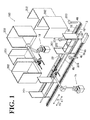
FIG. 1 is a perspective view of a robot system according to one embodiment; -
FIG. 2 is a plan view of the robot system according to the embodiment; -
FIG. 3 is a perspective view of a non-self-movable carriage; -
FIG. 4 is a perspective view of a self-movable carriage; -
FIG. 5 is a perspective view of a robot of the robot system according to the embodiment; -
FIG. 6 is a plan view of a synchronous movable body of the robot system according to the embodiment; -
FIG. 7 is a block diagram of the robot system according to the embodiment; -
FIG. 8 is a plan view of a synchronous movable body towing the non-self-movable carriage; -
FIG. 9 is a plan view of the synchronous movable body moving synchronously with the self-movable carriage; -
FIG. 10 is a flowchart of operations of the robot system according to the embodiment; -
FIG. 11 illustrates a state in which the robot of the robot system according to the embodiment takes out a workpiece; -
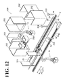
FIG. 12 illustrates a state in which the robot of the robot system according to the embodiment places the taken workpiece onto a stand; and -
FIG. 13 is a plan view of a modification of the synchronous movable body according to the embodiment. - The embodiments will now be described with reference to the accompanying drawings, wherein like reference numerals designate corresponding or identical elements throughout the various drawings.
- First, a configuration of a
robot system 100 according to this embodiment will be described by referring toFIGs. 1 to 9 . - As shown in
FIGs. 1 and2 , therobot system 100 includes tworobots movable bodies movable bodies - The two
robots guides carriage 201, on which a workpiece 200 (for example, a box) is placed. Also, a plurality ofstands 202 are disposed behind therobots workpiece 200 is placed on each of the plurality ofstands 202. Acamera 203 is disposed in the vicinity of the arrow X1 direction side of therunway 3, which is the direction in which thecarriage 201 moves (that is, thecamera 203 is disposed in the vicinity of the entrance side of therunway 3 from which thecarriage 201 enters the runway 3). Thecamera 203 captures an image of an arrangement state of theworkpiece 200 placed on thecarriage 201. Asensor 204 is disposed in the vicinity of the arrow X1 direction side of therunway 3, which is the direction in which thecarriage 201 moves (that is, thesensor 204 is disposed in the vicinity of the entrance side of therunway 3 from which thecarriage 201 enters the runway 3). Thesensor 204 detects that thecarriage 201 has reached a predetermined position on therunway 3. Examples of thesensor 204 include, but are not limited to, a light sensor to detect that light emitted from thesensor 204 has been shielded by thecarriage 201, and thereby detect that thecarriage 201 has reached a synchronization start position (which is a position at which therobots runway 3. - Two rod shaped
guides 4a and arack 5a are disposed on one side of therunway 3 for the carriage 201 (that is, on the arrow Y2 direction side). The rod shapedguides 4a guide the movement of a synchronousmovable body 2a. Therack 5a is engaged with a pinion (not shown) disposed in the synchronousmovable body 2a. Thus, the synchronousmovable body 2a moves on theguides 4a and therack 5a along therunway 3 for thecarriage 201. On the other side of therunway 3 for the carriage 201 (that is, on the arrow Y1 direction side), two rod shapedguides 4b and arack 5b are disposed. The two rodshaped guides 4b guide the movement of a synchronousmovable body 2b. Therack 5b is engaged with a pinion (not shown) disposed in the synchronousmovable body 2b. Thus, the synchronousmovable body 2b moves on theguides 4b and therack 5b along therunway 3 for thecarriage 201. Also, two rod shapedguides runway 3 for thecarriage 201. The two rod shapedguides carriage 201. - As shown in
FIGs. 3 and 4 , thecarriage 201 includes abase 211, twowalls 212, andwheels 213. Theworkpiece 200 is placed on thebase 211. The twowalls 212 each extend vertically. Here, in this embodiment, thecarriage 201 includes a non-self-movable carriage 201a (seeFIG. 3 ) and a self-movable carriage 201b (seeFIG. 4 ). The non-self-movable carriage 201a is driven into operation, while the self-movable carriage 201b is capable of self-movement. As shown inFIG. 4 , the self-movable configuration of the self-movable carriage 201b is made possible by mounting atowing device 205 as propeller, which is capable of self-movement along a predetermined route. The non-self-movable carriage 201a and the self-movable carriage 201b are examples of the "movable carriage". - Also as shown in
FIG. 5 , therobot 1a includes a robotmain body 11 and arobot hand 12. Therobot hand 12 is mounted to a distal end of the robotmain body 11 to hold theworkpiece 200. The robotmain body 11 includes abase 13 and arobot arm 14. - The
base 13 is secured to an installation surface. Therobot arm 14 according to this embodiment has six degrees of freedom. Therobot arm 14 includes a plurality of arm structures. Anarm structure 14a is coupled to the base 13 in a rotatable manner about a rotation axis A1, which is perpendicular to the installation surface. Anarm structure 14b is coupled to thearm structure 14a in a rotatable manner about a rotation axis A2, which is perpendicular to the rotation axis A1. An arm structure 14c is coupled to thearm structure 14b in a rotatable manner about a rotation axis A3, which is parallel to the rotation axis A2. Anarm structure 14d is coupled to the arm structure 14c in a rotatable manner about a rotation axis A4, which is perpendicular to the rotation axis A3. Anarm structure 14e is coupled to thearm structure 14d in a rotatable manner about a rotation axis A5, which is perpendicular to the rotation axis A4. Anarm structure 14f is coupled to thearm structure 14e in a rotatable manner about a rotation axis A6, which is perpendicular to the rotation axis A5. It is noted that "parallel" and "perpendicular", as used herein, are not only intended to mean precisely "parallel" and "perpendicular", respectively, but also intended more broadly to encompass slight differences from being "parallel" or "perpendicular". Each of the rotation axes A1 to A6 is equipped with a servo motor (joint). Each servo motor includes an encoder. The encoder detects a rotation position of the servo motor. Also each servo motor is coupled to therobot controller 15a (seeFIG. 7 ). Each servo motor operates based on a command from therobot controller 15a. The number of movable joints (that is, degrees of freedom) of therobot arm 14 will not be limited to six degrees of freedom. The robot arm may have any other number of degrees of freedom as necessary. - The
robot hand 12 is mounted to a distal end of therobot arm 14. Also, therobot hand 12 is equipped withgrippers workpiece 200. In plan view, thegrippers robot hand 12 coupled to thearm structure 14f). - The
robot 1b is similar in configuration to therobot 1a. - Also as shown in
FIG. 6 , the synchronousmovable body 2a includes amotor 21a and anencoder 22a. Here, in this embodiment, the synchronousmovable body 2a includes aprotrusion 23a, in addition to themotor 21a and theencoder 22a. Theprotrusion 23a synchronizes with thecarriage 201. In this embodiment, theprotrusion 23a has a rectangular parallelepiped shape. Also, theprotrusion 23a is capable of protruding over therunway 3 for the carriage 201 (seeFIGs. 8 and 9 ) and is capable of withholding into the carriage 201 (see the synchronousmovable body 2b ofFIGs. 8 and 9 ). Theprotrusion 23a protrudes when theprotrusion 23a synchronizes with thecarriage 201, while theprotrusion 23a withholds into thecarriage 201 after the end of the synchronization with the carriage 201 (that is, while theprotrusion 23a is waiting for thenext carriage 201, as described later). Theencoder 22a and theprotrusion 23a are respectively examples of the "position detector" and the "synchronization member". - Also in this embodiment, the
protrusion 23a includes acontact portion 24a on one side (that is, on the arrow X2 direction side) of theprotrusion 23a in the moving direction of thecarriage 201. Thecontact portion 24a is to contact thecarriage 201. Theprotrusion 23a includes adistance measurement device 25a on the other side (that is, on the arrow X1 direction side) of theprotrusion 23a. Thedistance measurement device 25a measures a distance to thecarriage 201. Thecontact portion 24a is a planar side surface of theprotrusion 23a on the arrow X2 direction side. Examples of thedistance measurement device 25a include, but are not limited to, a distance sensor to emit laser light to thecarriage 201 so as to measure the distance between thedistance measurement device 25a (that is, the synchronousmovable body 2a) and thecarriage 201. - Also in this embodiment, based on the rotation position of the
motor 21a, theencoder 22a detects the position of thecarriage 201 on therunway 3 for thecarriage 201. Specifically, based on the rotation position of themotor 21a, theencoder 22a detects the position of the synchronousmovable body 2a on theguides 4a (that is, on therack 5a). Theencoder 22a outputs a detection signal into the PLC (Programmable Logic Controller) 16 (seeFIG. 7 ). ThePLC 16 recognizes the position of the synchronousmovable body 2a as the position of thecarriage 201 on therunway 3. - The synchronous
movable body 2b includes amotor 21b, anencoder 22b, aprotrusion 23b, acontact portion 24b, and adistance measurement device 25b. The synchronousmovable body 2b is similar in configuration to the synchronousmovable body 2a. Theencoder 22b and theprotrusion 23b are respectively examples of the "position detector" and the "synchronization member". - Also in this embodiment, as shown in
FIGs. 8 and 9 , while the synchronousmovable body 2a (the synchronousmovable body 2b) is moving along therunway 3 for thecarriage 201 synchronously with the movement of thecarriage 201, the synchronousmovable body 2b (the synchronousmovable body 2a) waits at an entrance side of the runway 3 (which is on the arrow X1 direction side) for thenext carriage 201 to enter therunway 3 for thecarriage 201. After the synchronousmovable body 2a (the synchronousmovable body 2b) ends the synchronization with the movement of the carriage 201 (that is, after therobots movable body 2a (the synchronousmovable body 2b) moves to the entrance side of the runway 3 (which is on the arrow X1 direction side) from which thenext carriage 201 enters therunway 3 for thecarriage 201. - As shown in
FIG. 7 , therobot 1a (1b) is coupled to therobot controller 15a (15b) and to thePLC 16. ThePLC 16 is coupled to theencoder 22a (22b) of the synchronousmovable body 2a (synchronousmovable body 2b). ThePLC 16 is coupled to the camera 203 (seeFIG. 1 ) to capture an image of an arrangement state of theworkpiece 200 placed on thecarriage 201. ThePLC 16 is an example of the "controller". - Here, in this embodiment, the
PLC 16 controls therobots workpiece 200 out of thecarriage 201 synchronously with the movement of thecarriage 201 based on the detected position of thecarriage 201 on therunway 3. Specifically, thePLC 16 controls therobots workpieces 200 out of thecarriage 201 synchronously with the movement of thecarriage 201 in motion. - Also in this embodiment, as shown in
FIGs. 8 and 9 , thePLC 16 controls theprotrusion 23a (23b) of the synchronousmovable body 2a (2b) to move the synchronousmovable body 2a (2b) along the runway of thecarriage 201 synchronously with the movement of thecarriage 201. Specifically, as shown inFIG. 8 , when thecarriage 201 is the non-self-movable carriage 201a, which is incapable of self-movement, thePLC 16 controls the synchronousmovable body 2a (2b) to move with thecontact portion 24a (24b) of theprotrusion 23a (23b) in contact with the non-self-movable carriage 201a (more specifically, with an inner surface of the wall 212) from the arrow X1 direction. In this manner, thePLC 16 controls the synchronousmovable body 2a (2b) to move along therunway 3 synchronously with the movement of the non-self-movable carriage 201a. - As shown in
FIG. 9 , when thecarriage 201 is the self-movable carriage 201b, which is capable of self-movement, thePLC 16 controls the synchronousmovable body 2a (2b) to move while keeping the distance between the self-movable carriage 201b and theprotrusion 23a (23b) constant (that is, a constant distance d) based on the distance to the self-movable carriage 201b measured by thedistance measurement device 25a (25b). In this manner, thePLC 16 controls the synchronousmovable body 2a (2b) to move along therunway 3 synchronously with the movement of the self-movable carriage 201b. - Also as shown in
FIG. 2 , the synchronousmovable bodies robots area 101. In thearea 101, the robot system 100 (specifically, therobots movable bodies robots robots workpiece 200 out of thecarriage 201 in motion within thearea 101. - Next, by referring to
FIGs. 8 to 12 , operations of therobot system 100 according to the embodiment (that is, controlling operations by the PLC 16) will be described. In the initial state, the synchronousmovable bodies area 101 from which thecarriage 201 enters runway 3 (that is, on the arrow X1 direction side). - First, as shown in
FIG. 10 , at step S1, a determination is made as to whether thecarriage 201 has entered the area 101 (seeFIG. 2 ). When at step S1 a determination is made that thecarriage 201 has entered thearea 101, the processing proceeds to step S2. Information indicating whether thecarriage 201 has entered thearea 101 is input into thePLC 16 from the outside of the robot system 100 (or, a detector is provided in therobot system 100 to detect whether thecarriage 201 has entered). Then, at step S2, a determination is made as to whether thecarriage 201 having entered thearea 101 is the self-movable carriage 201b. Information indicating whether thecarriage 201 is the self-movable carriage 201b or the non-self-movable carriage 201a is provided to thePLC 16 from the outside of therobot system 100. When at step S2 a determination is made that thecarriage 201 is not the self-movable carriage 201b (that is, thecarriage 201 is the non-self-movable carriage 201a), the processing proceeds to step S3. Then, at step S3, the current mode is recognized as towing synchronization mode (which is a mode in which the non-self-movable carriage 201a is towed by the synchronousmovable bodies - Then, at step S4, as shown in
FIG. 8 , theprotrusion 23a of the synchronousmovable body 2a protrudes over therunway 3 for thecarriage 201. Then, the synchronousmovable body 2a moves in the arrow X2 direction. At the same time, theprotrusion 23a (more specifically, thecontact portion 24a of theprotrusion 23a) of the synchronousmovable body 2a is brought into contact with the inner surface of thewall 212 of the non-self-movable carriage 201a. Thus, the non-self-movable carriage 201a starts being towed at step S5. - Next, at step S6, a determination is made as to whether the non-self-
movable carriage 201a has reached a synchronization start position. Specifically, a determination is made as to whether the non-self-movable carriage 201a has reached the synchronization start position on therunway 3 based on whether light emitted from the sensor 204 (seeFIGs. 1 and2 ) has been shielded by the non-self-movable carriage 201a. Then, when a determination is made that the non-self-movable carriage 201a has reached the synchronization start position on therunway 3 at step S6, then at step S7, therobots workpieces 200 out of the non-self-movable carriage 201a synchronously with the movement of the non-self-movable carriage 201a, as shown inFIG. 11 . Therobots workpieces 200 based on an image of the non-self-movable carriage 201a captured by thecamera 203 in advance, that is, captured when the non-self-movable carriage 201a entered thearea 101 with theworkpieces 200 placed on the non-self-movable carriage 201a. Then, as shown inFIG. 12 , therobots workpieces 200 thus taken onto thestands 202. - After all the
workpieces 200 have been taken out of the non-self-movable carriage 201a, then at step S8, the synchronization of the synchronousmovable body 2a with the non-self-movable carriage 201a (that is, work of therobots robots movable carriage 201a leaves thearea 101. The synchronousmovable body 2a tows the non-self-movable carriage 201a until the non-self-movable carriage 201a leaves the area 101 (or, until a part of the non-self-movable carriage 201a leaves the area 101). Then, the synchronousmovable body 2a returns to the entrance side of the area 101 (on the arrow X1 direction side) and waits at the entrance side. - When at step S2 a determination is made that the
carriage 201 is the self-movable carriage 201b, the processing proceeds to step S9. At step S9, the current mode is recognized as distance synchronization mode (that is, a mode in which the distance between the self-movable carriage 201b and the synchronousmovable body 2a is kept constant, and in which the distance between the self-movable carriage 201b and the synchronousmovable body 2b is kept constant). Then, the processing proceeds to step S10. - Then, at step S10, as shown in
FIG. 9 , the self-movable carriage 201b moves in the arrow X2 direction. On the front side (in the arrow X2 direction) of the self-movable carriage 201b, theprotrusion 23a of the synchronousmovable body 2a protrudes over therunway 3 for the self-movable carriage 201b. Then, at step S11, thedistance measurement device 25a emits laser light to the self-movable carriage 201b to measure the distance to the self-movable carriage 201b. Then, at step S12, a determination is made as to whether the distance to the self-movable carriage 201b has reached the predetermined distance d set in advance (that is, whether the self-movable carriage 201b has come as close to theprotrusion 23a as the predetermined distance d). - Then, when at step S 12 a determination is made that the distance to the self-
movable carriage 201b has reached the predetermined distance d, then atstep S 13, therobots workpieces 200 out of the self-movable carriage 201b synchronously with the movement of the self-movable carriage 201b, as shown inFIG. 11 . Therobots workpieces 200 based on an image of the self-movable carriage 201b captured by thecamera 203 in advance, that is, captured when the self-movable carriage 201b entered thearea 101 with theworkpieces 200 placed on the self-movable carriage 201b. Then, as shown inFIG. 12 , therobots workpieces 200 thus taken onto thestands 202. Atstep S 14, also after the synchronization has started, the distance to the self-movable carriage 201b is measured, and the synchronousmovable body 2a moves so as to keep the distance to the self-movable carriage 201b at the constant distance d. - After all the
workpieces 200 have been taken out of the self-movable carriage 201b, then atstep S 15, synchronization of the synchronousmovable body 2a with the self-movable carriage 201b (that is, work of therobots movable body 2a moves to the entrance side (that is, to the arrow X1 direction side) of thearea 101 and waits at the entrance side. - When the
next carriage 201 enters therunway 3 for the carriage 201 (that is, the area 101), the other synchronousmovable body 2b starts synchronization with thecarriage 201. In other words, the synchronousmovable bodies carriage 201. - As has been described hereinbefore, in this embodiment, the synchronous
movable body 2a (2b) moves along the predetermined runway 3 (on which thecarriage 201 moves) synchronously with the movement of thecarriage 201. The synchronousmovable body 2a (2b) includes theencoder 22a (22b) to detect the position of thecarriage 201 on thepredetermined runway 3. This ensures detection of the position of thecarriage 201 by the synchronousmovable body 2a (2b) even when thecarriage 201 is incapable of detecting of its own position. This, in turn, ensures that therobots carriage 201 synchronously with the movement of thecarriage 201. - Also in this embodiment, as described above, the synchronous
movable body 2a (2b) includes, in addition to theencoder 22a (22b), theprotrusion 23a (23b) to synchronize with thecarriage 201. ThePLC 16 controls theprotrusion 23a (23b) to move the synchronousmovable body 2a (2b) along thepredetermined runway 3 synchronously with the movement of thecarriage 201. The use of theprotrusion 23a (23b) facilitates the movement of the synchronousmovable body 2a (2b) synchronously with the movement of thecarriage 201. When the synchronousmovable body 2a (2b) does not synchronize with the movement of thecarriage 201, theprotrusion 23a (23b) withholds into the synchronousmovable body 2a (2b). This eliminates or minimizes contact between the synchronousmovable body 2a (2b) and thecarriage 201. - Also in this embodiment, as described above, the
PLC 16 controls the synchronousmovable body 2a (2b) to move with theprotrusion 23a (23b) in contact with the non-self-movable carriage 201a, so as to control the synchronousmovable body 2a (2b) to move along thepredetermined runway 3 synchronously with the movement of the non-self-movable carriage 201a. This ensures that the synchronousmovable body 2a (2b) readily moves the non-self-movable carriage 201a. - Also in this embodiment, as described above, the
distance measurement device 25a (25b) is disposed on theprotrusion 23a (23b). ThePLC 16 controls the synchronousmovable body 2a (2b) to move while keeping the distance between the self-movable carriage 201b and theprotrusion 23a (23b) constant based on the distance to the self-movable carriage 201b measured by thedistance measurement device 25a (25b). In this manner,PLC 16 controls the synchronousmovable body 2a (2b) to move along thepredetermined runway 3 synchronously with the movement of the self-movable carriage 201b. Generally, the self-movable carriage 201b is designed to automatically make a stop when the self-movable carriage 201b collides with some object. In this respect, the synchronousmovable body 2a (2b) moves in a non-contact state in which the self-movable carriage 201b and theprotrusion 23a (23b) are kept at a constant distance from each other. This eliminates or minimizes contact between the self-movable carriage 201b and theprotrusion 23a (23b). This, in turn, ensures that the synchronousmovable body 2a (2b) readily move synchronously with the movement of the self-movable carriage 201b without stopping the self-movable carriage 201b. - Also in this embodiment, as described above, the
protrusion 23a (23b) includes thecontact portion 24a (24b) and thedistance measurement device 25a (25b). Thecontact portion 24a (24b) is disposed on one side of theprotrusion 23a (23b) in the moving direction of thecarriage 201 to contact thecarriage 201. Thedistance measurement device 25a (25b) is disposed on the other side of theprotrusion 23a (23b) to measure the distance to thecarriage 201. This ensures that thecontact portion 24a (24b) contacts thecarriage 201 from behind thecarriage 201 to tow thecarriage 201, and that thedistance measurement device 25a (25b) measures the distance to thecarriage 201 from the front side of thecarriage 201. Additionally, by providing theprotrusion 23a (23b) with thecontact portion 24a (24b) on one side and thedistance measurement device 25a (25b) on the other side (that is, providing oneprotrusion 23a (23b) with thecontact portion 24a (24b) and thedistance measurement device 25a (25b)), a simpler configuration is ensured, as opposed to the case where thecontact portion 24a (24b) and thedistance measurement device 25a (25b) are disposed on separate protrusions. - Also in this embodiment, as described above, while the synchronous
movable body 2a (or the synchronousmovable body 2b) is moving along thepredetermined runway 3 synchronously with the movement of thecarriage 201, the synchronousmovable body 2b (as well as the synchronousmovable body 2a) waits at the entrance side of thepredetermined runway 3 for thenext carriage 201 to enter thepredetermined runway 3. Thus, after the synchronization of the synchronousmovable body 2a (or the synchronousmovable body 2b) with theprevious carriage 201 has ended, the synchronousmovable body 2b (the synchronousmovable body 2a) synchronizes with thenext carriage 201. This eliminates the need for waiting for the synchronousmovable body 2a (or the synchronousmovable body 2b) to return to the entrance side of thearea 101, resulting in shortened tact time. - Also in this embodiment, as described above, the
PLC 16 controls therobots workpieces 200 out of thecarriage 201 synchronously with the movement of thecarriage 201 based on the detected position of thecarriage 201 on thepredetermined runway 3. This ensures that therobots workpieces 200 out of thecarriage 201 synchronously with the movement of thecarriage 201. - Also in this embodiment, as described above, the
PLC 16 theencoder 22a (22b) to detect the position of thecarriage 201 on thepredetermined runway 3 based on the rotation position of themotor 21a (21b). This facilitates detection of the position of the synchronousmovable body 2a (2b), and facilitates detection of the position of thecarriage 201. - Obviously, numerous modifications and variations of the present disclosure are possible in light of the above teachings. It is therefore to be understood that within the scope of the appended claims, the present disclosure may be practiced otherwise than as specifically described herein.
- For example, in the above-described embodiment, the robots have been illustrated as taking out the workpieces out of the self-movable carriage. The robots may also perform other work than taking out the workpieces out of the self-movable carriage (examples including, but not limited to, placing the workpieces onto the self-movable carriage, and cutting the workpieces).
- In the above-described embodiment, the "controller" has been illustrated as the PLC. A specific configuration of the "controller", that is, the control system, is selectable conveniently. An example of the "controller" is a robot controller. Other examples of the "controller" include a PLC and a robot controller, and any of versatile controllers. It is also possible to use all of the foregoing.
- In the above-described embodiment, the protrusion protrudes from the synchronous movable body and contacts the non-self-movable carriage, thereby synchronizing the synchronous movable body with the movement of the non-self-movable carriage. It is also possible to use a configuration other than the contact of the protrusion with the non-self-movable carriage to synchronize the synchronous movable body with the movement of the non-self-movable carriage (examples including, but not limited to, use of magnetic force of an electromagnet to move the non-self-movable carriage).
- In the above-described embodiment, a single protrusion has been illustrated as being provided with the contact portion, which is to contact the self-movable carriage, and provided with the distance measurement device. The contact portion, which is to contact the self-movable carriage, and the distance measurement device may also be disposed on separate protrusions.
- In the above-described embodiment, the distance measurement device has been illustrated as being disposed on the protrusion. The distance measurement device may also be disposed at a portion other than the protrusion.
- In the above-described embodiment, the contact portion to contact the carriage has been illustrated as being a planar side surface of the protrusion. Another possible example is a modification as shown in
FIG. 13 , where the carriage is acarriage 222 withpillars 221 at four corners. In this case, a protrusion 23c of a synchronous movable body 2c has a contact portion 24c with a claw shape (a V-shaped concave in plan view) that is to contact the carriage 222 (a pillar 221). This ensures stable towing of the self-movable carriage 222. The protrusion 23c is an example of the "synchronization member". - In the above-described embodiment, two synchronous movable bodies have been illustrated. It is also possible to provide one or more than three synchronous movable bodies.
- In the above-described embodiment, two robots have been illustrated. It is also possible to provide one or more than three robots.
- 1a, 1b
- Robot
- 2a, 2b, 2c
- Synchronous movable body (first synchronous movable body and second synchronous movable body)
- 3
- Runway
- 16 PLC
- (controller)
- 21a, 21b
- Motor
- 22a, 22b
- Encoder (position detector)
- 23a, 23b, 23c
- Protrusion (synchronization member)
- 24a, 24b, 24c
- Contact portion
- 25a, 25c
- Distance measurement device
- 100
- Robot system
- 200
- Workpiece
- 201, 222
- Carriage
- 201a
- Non-self-movable carriage (carriage)
- 201b
- Self-movable carriage (carriage)
Claims (11)
- A robot system 100, characterized by:a robot 1a, 1b configured to perform a predetermined work with respect to a workpiece placed on at least one carriage 201 of one or more carriages moving along a predetermined runway 3;a synchronous movable body 2a, 2b configured to move along the predetermined runway 3 synchronously with movement of the at least one carriage 201, the synchronous movable body 2a, 2b comprising a position detector 22a, 22b configured to detect a position of the at least one carriage 201 on the predetermined runway 3; anda controller 15a, 15b configured to control the robot 1a, 1b to perform the predetermined work with respect to the workpiece placed on the at least one carriage 201 synchronously with the movement of the at least one carriage 201 based on the detected position of the at least one carriage 201 on the predetermined runway 3.
- The robot system 100 according to claim 1,
wherein the synchronous movable body 2a, 2b further comprises a synchronization member 23a, 23b, 23c configured to synchronize with the at least one carriage 201, and
wherein the controller 15a, 15b is configured to control the synchronization member 23a, 23b, 23c to move the synchronous movable body 2a, 2b along the predetermined runway 3 synchronously with the movement of the at least one carriage 201. - The robot system 100 according to claim 2,
wherein the at least one carriage 201 is a non-self-movable carriage 201a configured to be driven, and
wherein the controller 15a, 15b is configured to control the synchronous movable body 2a, 2b to move with the synchronization member 23a, 23b, 23c in contact with the non-self-movable carriage 201a, so as to control the synchronous movable body 2a, 2b to move along the predetermined runway 3 synchronously with the movement of the non-self-movable carriage 201a. - The robot system 100 according to claim 3,
wherein the synchronization member 23a, 23b, 23c comprises a protrusion 23a, 23b, 23c configured to protrude over the predetermined runway 3, and
wherein the controller 15a, 15b is configured to control the synchronous movable body 2a, 2b to move with the protrusion 23a, 23b, 23c in contact with the non-self-movable carriage 201a, so as to control the synchronous movable body 2a, 2b to move along the predetermined runway 3 synchronously with the movement of non-self-movable carriage 201a. - The robot system 100 according to claim 2,
wherein the at least one carriage 201 is a self-movable carriage 201b having propeller, wherein the synchronous movable body 2a, 2b further comprises a distance measurement device 25a, 25b configured to measure a distance to the self-movable carriage 201b, and
wherein the controller 15a, 15b is configured to control the synchronous movable body 2a, 2b to move while keeping a distance between the self-movable carriage 201b and the synchronization member 23a, 23b, 23c constant based on the distance to the self-movable carriage 201b measured by the distance measurement device 25a, 25b, so as to control the synchronous movable body 2a, 2b to move along the predetermined runway 3 synchronously with the movement of the self-movable carriage 201b. - The robot system 100 according to claim 5,
wherein the synchronization member 23a, 23b, 23c comprises a protrusion 23a, 23b, 23c configured to protrude over the predetermined runway 3,
wherein the distance measurement device 25a, 25b is disposed on the protrusion 23a, 23b,23c,and
wherein the controller 15a, 15b is configured to control the synchronous movable body 2a, 2b to move while keeping the distance between the self-movable carriage 201b and the protrusion 23a, 23b, 23c constant based on the distance to the self-movable carriage 201b measured by the distance measurement device 25a, 25b, so as to control the synchronous movable body 2a, 2b to move along the predetermined runway 3 synchronously with the movement of the self-movable carriage 201b. - The robot system 100 according to any one of claims 2 to 6,
wherein the synchronization member 23a, 23b, 23c comprises a protrusion 23a, 23b, 23c configured to protrude over the predetermined runway 3, and
wherein the protrusion 23a, 23b, 23c comprises
a contact portion 24a, 24b, 24c on one side of the protrusion 23a, 23b, 23c in a moving direction of the at least one carriage 201 to contact the at least one carriage 201, and
a distance measurement device 25a, 25b on another side of the protrusion 23a, 23b, 23c to measure a distance to the at least one carriage 201. - The robot system 100 according to any one of claims 1 to 7,
wherein the synchronous movable body 2a, 2b comprises a first synchronous movable body 2a, 2b and a second synchronous movable body 2a, 2b,
wherein the first synchronous movable body 2a, 2b is configured to move along the predetermined runway 3 synchronously with the movement of the at least one carriage 201, and
wherein while the first synchronous movable body 2a, 2b is moving along the predetermined runway 3 synchronously with the movement of the at least one carriage 201, the second synchronous movable body 2a, 2b is configured to wait at an entrance side of the predetermined runway 3 for a next carriage 201 to enter the predetermined runway 3. - The robot system according to any one of claims 1 to 8, wherein the controller 15a, 15b is configured to control the robot 1a, 1b to take the workpiece out of the at least one carriage 201 synchronously with the movement of the carriage 201 based on the detected position of the at least one carriage 201 on the predetermined runway 3.
- The robot system 100 according to any one of claims 1 to 9,
wherein the synchronous movable body 2a, 2b further comprises a motor configured to move the synchronous movable body 2a, 2b, and
wherein the controller 15a, 15b is configured to control the position detector 22a, 22b to detect the position of the carriage 201 on the predetermined runway 3 based on a rotation position of the motor. - A robot working method, characterized by:moving a synchronous movable body 2a, 2b along a predetermined runway 3 synchronously with movement of a carriage 201 along the predetermined runway 3 so as to detect a position of the carriage 201 on the predetermined runway 3, the synchronous movable body 2a, 2b comprising a position detector 22a, 22b; andcontrolling a robot 1a, 1b to perform a predetermined work with respect to a workpiece placed on the carriage 201 synchronously with the movement of the carriage 201 based on the detected position of the carriage 201 on the predetermined runway 3.
Applications Claiming Priority (1)
| Application Number | Priority Date | Filing Date | Title |
|---|---|---|---|
| JP2013051108A JP5768826B2 (en) | 2013-03-14 | 2013-03-14 | Robot system and robot working method |
Publications (2)
| Publication Number | Publication Date |
|---|---|
| EP2784612A2 true EP2784612A2 (en) | 2014-10-01 |
| EP2784612A3 EP2784612A3 (en) | 2015-08-19 |
Family
ID=50239397
Family Applications (1)
| Application Number | Title | Priority Date | Filing Date |
|---|---|---|---|
| EP14157190.1A Withdrawn EP2784612A3 (en) | 2013-03-14 | 2014-02-28 | Robot system and robot working method |
Country Status (4)
| Country | Link |
|---|---|
| US (1) | US20140277716A1 (en) |
| EP (1) | EP2784612A3 (en) |
| JP (1) | JP5768826B2 (en) |
| CN (1) | CN104044150A (en) |
Cited By (5)
| Publication number | Priority date | Publication date | Assignee | Title |
|---|---|---|---|---|
| WO2017153504A1 (en) * | 2016-03-08 | 2017-09-14 | KBee AG | Robot system, method for controlling a robot system, and processing system |
| US10625414B2 (en) | 2015-08-14 | 2020-04-21 | Franka Emika Gmbh | Robotic system and housing part for such robotic system |
| US10843344B2 (en) | 2015-10-08 | 2020-11-24 | Sami Haddadin | Robot system |
| US11358275B2 (en) | 2016-04-20 | 2022-06-14 | Franka Emika Gmbh | Drive unit for a robot and method for manufacturing the same |
| US11623355B2 (en) | 2016-04-20 | 2023-04-11 | Kastanienbaum GmbH | Method for producing a robot and device for carrying out said method |
Families Citing this family (7)
| Publication number | Priority date | Publication date | Assignee | Title |
|---|---|---|---|---|
| CN104476027B (en) * | 2014-11-14 | 2016-01-20 | 南京熊猫电子股份有限公司 | A kind of group control device of multirobot welding system and method thereof |
| CN104476029B (en) * | 2014-11-19 | 2016-11-23 | 柳州市益宏汽车配件有限公司 | Robot synchronous coordination welding gun system |
| JP6549013B2 (en) * | 2015-10-09 | 2019-07-24 | キリン株式会社 | Container transport system |
| DE102015014485A1 (en) | 2015-11-10 | 2017-05-24 | Kuka Roboter Gmbh | Calibrating a system with a conveyor and at least one robot |
| CN109562516A (en) * | 2016-06-30 | 2019-04-02 | Abb瑞士股份有限公司 | The processing component in punch line |
| CN109034596A (en) | 2018-07-19 | 2018-12-18 | 北京北方华创微电子装备有限公司 | A method and device for optimal scheduling of materials |
| CN109625957B (en) * | 2018-12-29 | 2024-11-05 | 广州瑞松智能科技股份有限公司 | A feeding mechanism using 3D vision and robot gripper |
Family Cites Families (23)
| Publication number | Priority date | Publication date | Assignee | Title |
|---|---|---|---|---|
| US3958682A (en) * | 1973-11-05 | 1976-05-25 | Martin Paul S | Coordination of robot and conveyor |
| US4086522A (en) * | 1976-09-08 | 1978-04-25 | Unimation, Inc. | Computer assisted teaching arrangement for conveyor line operation |
| JPS58179285U (en) * | 1982-05-27 | 1983-11-30 | 関東自動車工業株式会社 | Automotive engine assembly equipment |
| US4615274A (en) * | 1982-06-29 | 1986-10-07 | Hoehn Robert A | Indexing conveyor for robotic production operations |
| JPS62203789A (en) * | 1986-03-04 | 1987-09-08 | 日産自動車株式会社 | Follow-up controller |
| DE4021330C2 (en) * | 1990-07-03 | 1996-10-24 | Bayerische Motoren Werke Ag | Method for operating a robot and a device therefor |
| DE4114215A1 (en) * | 1991-05-01 | 1992-11-05 | Focke & Co | DEVICE FOR LOADING PALLETS WITH BOXES |
| JPH06115426A (en) * | 1992-10-08 | 1994-04-26 | Daifuku Co Ltd | Transport equipment |
| JP3172287B2 (en) * | 1992-11-09 | 2001-06-04 | マツダ株式会社 | Film defect detector |
| NL9400615A (en) * | 1994-04-18 | 1995-12-01 | Car Recycling Systems | Device for scrapping cars. |
| JP4151123B2 (en) * | 1998-05-08 | 2008-09-17 | 日産自動車株式会社 | Work following device |
| US6579053B1 (en) * | 1999-03-15 | 2003-06-17 | Abb Flexible Automation, Inc. | Robotic containerization and palletizing system |
| US6892890B2 (en) * | 2001-01-16 | 2005-05-17 | Abb Automation, Inc. | Dynamic sortation of items in a containerization system |
| JP4453626B2 (en) * | 2005-07-25 | 2010-04-21 | 株式会社ダイフク | Transport equipment |
| US20080072548A1 (en) * | 2006-09-05 | 2008-03-27 | Peter Guttinger | Continuous loading system |
| JP4443615B2 (en) * | 2008-02-27 | 2010-03-31 | トヨタ自動車株式会社 | Power assist device and control method thereof |
| JP4621789B2 (en) * | 2009-06-02 | 2011-01-26 | ファナック株式会社 | Article transport robot system |
| JP2011140077A (en) * | 2010-01-06 | 2011-07-21 | Honda Motor Co Ltd | Processing system and processing method |
| JP5508895B2 (en) * | 2010-02-22 | 2014-06-04 | 本田技研工業株式会社 | Processing system and processing method |
| JP5650841B2 (en) * | 2010-07-09 | 2015-01-07 | 株式会社ダイフク | Cart type conveyor |
| US8571700B2 (en) * | 2010-08-02 | 2013-10-29 | Brightstar Corp. | Robotic picking line for serialized products |
| US8700205B2 (en) * | 2011-08-05 | 2014-04-15 | GM Global Technology Operations LLC | Moving stop station for robotic assembly |
| US8738180B2 (en) * | 2011-12-14 | 2014-05-27 | GM Global Technology Operations LLC | Robot control during an e-stop event |
-
2013
- 2013-03-14 JP JP2013051108A patent/JP5768826B2/en not_active Expired - Fee Related
- 2013-12-26 CN CN201310738755.7A patent/CN104044150A/en active Pending
-
2014
- 2014-02-28 EP EP14157190.1A patent/EP2784612A3/en not_active Withdrawn
- 2014-03-13 US US14/207,661 patent/US20140277716A1/en not_active Abandoned
Non-Patent Citations (1)
| Title |
|---|
| None * |
Cited By (5)
| Publication number | Priority date | Publication date | Assignee | Title |
|---|---|---|---|---|
| US10625414B2 (en) | 2015-08-14 | 2020-04-21 | Franka Emika Gmbh | Robotic system and housing part for such robotic system |
| US10843344B2 (en) | 2015-10-08 | 2020-11-24 | Sami Haddadin | Robot system |
| WO2017153504A1 (en) * | 2016-03-08 | 2017-09-14 | KBee AG | Robot system, method for controlling a robot system, and processing system |
| US11358275B2 (en) | 2016-04-20 | 2022-06-14 | Franka Emika Gmbh | Drive unit for a robot and method for manufacturing the same |
| US11623355B2 (en) | 2016-04-20 | 2023-04-11 | Kastanienbaum GmbH | Method for producing a robot and device for carrying out said method |
Also Published As
| Publication number | Publication date |
|---|---|
| CN104044150A (en) | 2014-09-17 |
| EP2784612A3 (en) | 2015-08-19 |
| JP5768826B2 (en) | 2015-08-26 |
| JP2014176910A (en) | 2014-09-25 |
| US20140277716A1 (en) | 2014-09-18 |
Similar Documents
| Publication | Publication Date | Title |
|---|---|---|
| US20140277716A1 (en) | Robot system and robot working method | |
| CN113544069B (en) | Robot hand, robot and robot system | |
| US12002007B2 (en) | Robotic system with automated package scan and registration mechanism and methods of operating the same | |
| EP2899148B1 (en) | Parallel link robot, hand for parallel link robot, and parallel link robot system | |
| CN110125906B (en) | Work robot system | |
| EP1621296A1 (en) | Transfer robot system comprising a manipulator and a temporary container depository moving synchronously with the manipulator | |
| EP2783807A2 (en) | Robot system, calibration method, and method for producing to-be-processed material | |
| EP3392002A1 (en) | Information processing apparatus, measuring apparatus, system, interference determination method, and article manufacturing method | |
| EP4484343A2 (en) | Measurement system on a conveyor | |
| CN108349078A (en) | The protection zone of effector system adjusts | |
| CN109318244B (en) | Control device for articulated robot | |
| US10940590B2 (en) | Calibrating a system with a conveying means and at least one robot | |
| CN110271019B (en) | Control device and control method for cooperative robot | |
| US10189521B2 (en) | Assembly platform | |
| CN110385695A (en) | Checking job robot system and Work robot | |
| JP5618067B2 (en) | Bulk picking apparatus and method | |
| JP2022104733A (en) | Mobile robot with robot arm | |
| CN120246695A (en) | Automatic palletizing control system based on visual positioning | |
| EP3718709B1 (en) | Component moving device | |
| JPH0623684A (en) | Work transfer robot with visual processing function | |
| WO2025103557A1 (en) | Aligning a robotic arm to an object | |
| CN209536510U (en) | Truck Unloader Self-Aligning Interface | |
| JP2023136650A (en) | Vehicular body conveying system | |
| Guo | Intelligent Collaborative Gantry Crane | |
| JPWO2019064913A1 (en) | Mobile and production systems |
Legal Events
| Date | Code | Title | Description |
|---|---|---|---|
| 17P | Request for examination filed |
Effective date: 20140228 |
|
| AK | Designated contracting states |
Kind code of ref document: A2 Designated state(s): AL AT BE BG CH CY CZ DE DK EE ES FI FR GB GR HR HU IE IS IT LI LT LU LV MC MK MT NL NO PL PT RO RS SE SI SK SM TR |
|
| AX | Request for extension of the european patent |
Extension state: BA ME |
|
| PUAI | Public reference made under article 153(3) epc to a published international application that has entered the european phase |
Free format text: ORIGINAL CODE: 0009012 |
|
| PUAL | Search report despatched |
Free format text: ORIGINAL CODE: 0009013 |
|
| AK | Designated contracting states |
Kind code of ref document: A3 Designated state(s): AL AT BE BG CH CY CZ DE DK EE ES FI FR GB GR HR HU IE IS IT LI LT LU LV MC MK MT NL NO PL PT RO RS SE SI SK SM TR |
|
| AX | Request for extension of the european patent |
Extension state: BA ME |
|
| RIC1 | Information provided on ipc code assigned before grant |
Ipc: B25J 9/16 20060101ALI20150710BHEP Ipc: B25J 9/00 20060101ALI20150710BHEP Ipc: G05B 19/418 20060101AFI20150710BHEP |
|
| R17P | Request for examination filed (corrected) |
Effective date: 20150917 |
|
| RBV | Designated contracting states (corrected) |
Designated state(s): AL AT BE BG CH CY CZ DE DK EE ES FI FR GB GR HR HU IE IS IT LI LT LU LV MC MK MT NL NO PL PT RO RS SE SI SK SM TR |
|
| 17Q | First examination report despatched |
Effective date: 20170222 |
|
| STAA | Information on the status of an ep patent application or granted ep patent |
Free format text: STATUS: THE APPLICATION IS DEEMED TO BE WITHDRAWN |
|
| 18D | Application deemed to be withdrawn |
Effective date: 20170705 |