EP2784537B1 - Inversion method and apparatus based on polarimetric interferometric synthetic aperture radar - Google Patents
Inversion method and apparatus based on polarimetric interferometric synthetic aperture radar Download PDFInfo
- Publication number
- EP2784537B1 EP2784537B1 EP14162311.6A EP14162311A EP2784537B1 EP 2784537 B1 EP2784537 B1 EP 2784537B1 EP 14162311 A EP14162311 A EP 14162311A EP 2784537 B1 EP2784537 B1 EP 2784537B1
- Authority
- EP
- European Patent Office
- Prior art keywords
- correlation
- images
- estimation value
- measured
- coefficient
- Prior art date
- Legal status (The legal status is an assumption and is not a legal conclusion. Google has not performed a legal analysis and makes no representation as to the accuracy of the status listed.)
- Not-in-force
Links
- 238000000034 method Methods 0.000 title claims description 91
- 239000011159 matrix material Substances 0.000 claims description 44
- 238000010586 diagram Methods 0.000 description 16
- 238000004364 calculation method Methods 0.000 description 4
- 238000005070 sampling Methods 0.000 description 4
- 238000004088 simulation Methods 0.000 description 3
- 230000003190 augmentative effect Effects 0.000 description 2
- 238000000354 decomposition reaction Methods 0.000 description 2
- 238000002474 experimental method Methods 0.000 description 2
- 238000012545 processing Methods 0.000 description 2
- 238000012935 Averaging Methods 0.000 description 1
- 230000003044 adaptive effect Effects 0.000 description 1
- 239000002131 composite material Substances 0.000 description 1
- 238000007796 conventional method Methods 0.000 description 1
- 230000007547 defect Effects 0.000 description 1
- 230000001419 dependent effect Effects 0.000 description 1
- 230000000694 effects Effects 0.000 description 1
- 238000005516 engineering process Methods 0.000 description 1
- 230000002349 favourable effect Effects 0.000 description 1
- 238000005305 interferometry Methods 0.000 description 1
- 238000005457 optimization Methods 0.000 description 1
- 238000010587 phase diagram Methods 0.000 description 1
- 238000004445 quantitative analysis Methods 0.000 description 1
- 230000009466 transformation Effects 0.000 description 1
- 230000000007 visual effect Effects 0.000 description 1
Images



Classifications
-
- G—PHYSICS
- G01—MEASURING; TESTING
- G01S—RADIO DIRECTION-FINDING; RADIO NAVIGATION; DETERMINING DISTANCE OR VELOCITY BY USE OF RADIO WAVES; LOCATING OR PRESENCE-DETECTING BY USE OF THE REFLECTION OR RERADIATION OF RADIO WAVES; ANALOGOUS ARRANGEMENTS USING OTHER WAVES
- G01S13/00—Systems using the reflection or reradiation of radio waves, e.g. radar systems; Analogous systems using reflection or reradiation of waves whose nature or wavelength is irrelevant or unspecified
- G01S13/88—Radar or analogous systems specially adapted for specific applications
- G01S13/89—Radar or analogous systems specially adapted for specific applications for mapping or imaging
- G01S13/90—Radar or analogous systems specially adapted for specific applications for mapping or imaging using synthetic aperture techniques, e.g. synthetic aperture radar [SAR] techniques
- G01S13/9021—SAR image post-processing techniques
- G01S13/9023—SAR image post-processing techniques combined with interferometric techniques
-
- G—PHYSICS
- G01—MEASURING; TESTING
- G01S—RADIO DIRECTION-FINDING; RADIO NAVIGATION; DETERMINING DISTANCE OR VELOCITY BY USE OF RADIO WAVES; LOCATING OR PRESENCE-DETECTING BY USE OF THE REFLECTION OR RERADIATION OF RADIO WAVES; ANALOGOUS ARRANGEMENTS USING OTHER WAVES
- G01S13/00—Systems using the reflection or reradiation of radio waves, e.g. radar systems; Analogous systems using reflection or reradiation of waves whose nature or wavelength is irrelevant or unspecified
- G01S13/88—Radar or analogous systems specially adapted for specific applications
- G01S13/89—Radar or analogous systems specially adapted for specific applications for mapping or imaging
- G01S13/90—Radar or analogous systems specially adapted for specific applications for mapping or imaging using synthetic aperture techniques, e.g. synthetic aperture radar [SAR] techniques
- G01S13/904—SAR modes
- G01S13/9076—Polarimetric features in SAR
Definitions
- the disclosure relates generally to the application technology of Polarimetric Interferometric Synthetic Aperture Radar (PoLInSAR), and in particular to an inversion method and apparatus based on the PoLInSAR.
- PoLInSAR Polarimetric Interferometric Synthetic Aperture Radar
- a conventional forest parameter inversion method is a conventional three-stage inversion method proposed by scholars Cloude and Pathanassiou, which is based on an RVOG two-layer vegetation model and divides an inversion process into three steps including: correlation coefficient estimation and line fitting, ground surface phase estimation, and volume scattering decorrelation estimation and parameter estimation.
- a line fitting error and a volume scattering decorrelation estimation error greatly influence inversion precision.
- the line fitting error may directly influence the precision of the ground surface phase estimation, and the ground surface phase error directly influences tree height inversion results, thus, the line fitting is a basic step of the three-stage inversion method, and the line fitting error is required to be minimized.
- the line fitting method generally adopts least squares.
- the line fitting method adopting the least squares is simple, but there is a defect that only an independent variable error is considered and no dependent variable error is considered, which results in an error in the fitting.
- the volume scattering decorrelation coefficient is a point on a visual line segment of the fitted line which is farthest away from a ground surface phase point.
- the conventional volume scattering decorrelation coefficient may be approximated to an HV channel correlation coefficient, which however may result in an underestimation of the forest height.
- LULU TAN ET AL "Improved three-stage inversion process for forest height inversion with PolInSAR data",RADAR (RADAR), 2011 IEEE CIE INTERNATIONAL CONFERENCE ON, IEEE, 24 October 2011 (2011-10-24), pages 1394-1397, XP032124127 , discloses an improved three-stage inversion process wherein coherence estimation is performed by adaptive averaging.
- the disclosure provides an inversion method and apparatus based on PoLInSAR, which can improve inversion precision.
- An inversion method based on PoLInSAR which includes:
- the step that line fitting is performed, by using total least squares, on a correlation coefficient estimation value acquired from the PoLInSAR image data to determine a ground surface phase estimation value of the object to be measured may include:
- the step that a volume scattering decorrelation coefficient is acquired through a correlation regional boundary acquired from the PoLInSAR image data and a fitted line may include:
- the step that a correlation regional boundary of the master images and the slave images is determined may include:
- the step that two intersection points of the fitted line and the correlation regional boundary are determined may include:
- An apparatus based on PoLInSAR which includes a ground surface phase determining module, a volume scattering decorrelation coefficient determining module and a parameter determining module.
- the ground surface phase determining module is configured to: acquire a set of PoLInSAR image data of an object to be measured, and perform line fitting, by using total least squares, on a correlation coefficient estimation value acquired from the PoLInSAR image data to determine a ground surface phase estimation value of the object to be measured; the volume scattering decorrelation coefficient determining module is configured to acquire a volume scattering decorrelation coefficient through a correlation regional boundary acquired from the PoLInSAR image data and a fitted line; and the parameter determining module is configured to perform inversion on the object to be measured by establishing a lookup table to acquire an inversion parameter of the object to be measured as a parameter estimation value of the object to be measured.
- the ground surface phase determining module may be further configured to:
- the volume scattering decorrelation coefficient determining module may be further configured to:
- the volume scattering decorrelation coefficient determining module may be further configured to:
- the parameter determining module may be further configured to: establish an objective function of the object to be measured, according to a scattering mechanism of the master images and the slave images, a polarimetric cross-correlation matrix of the master images and the slave images, and a correlation matrix of the master images and a correlation matrix of the slave images, determine extreme values of the objective function through a Lagrange multiplier method, and take the extreme values of the objective function as two intersection points of the fitted line and the correlation regional boundary.
- a set of PoLInSAR image data of an object to be measured is acquired, line fitting is performed, by using total least squares, on a correlation coefficient estimation value acquired from the PoLInSAR image data to determine a ground surface phase estimation value of the object to be measured; a volume scattering decorrelation coefficient is acquired through the correlation regional boundary acquired from the PoLInSAR image data and the fitted line; inversion is performed on the object to be measured by establishing a lookup table to acquire an inversion parameter of the object to be measured as a parameter estimation value of the object to be measured.
- the method and apparatus of the disclosure can reduce line fitting error effectively, estimate a volume scattering decorrelation coefficient precisely and then obtain a more precise forest parameter, and accordingly improve the inversion precision of the forest parameter.
- the method provided by the disclosure is simple and practicable, and especially applicable to the inversion of forest parameters, an inversion result of tree height can be much closer to the actual height, which is more favourable to a practical application of a remote sensing image.
- the method provided by the disclosure is simple and practicable, and can perform precise inversion on a crop parameter.
- Fig. 1 is a flow diagram of an inversion method based on PoLInSAR according to the disclosure. As shown in Fig. 1 , the inversion method may include steps 101, 102 and 103.
- step 101 a set of PoLInSAR image data of an object to be measured is acquired, and line fitting is performed, by using total least squares, on a correlation coefficient estimation value acquired from the PoLInSAR image data to determine a ground surface phase estimation value of the object to be measured.
- the PoLInSAR image data may include four master images and four slave images.
- polarimetric data of the same object to be measured is acquired by two antennas.
- a first antenna of the two antennas acquires master image data corresponding to an HH channel, an HV channel, a VH channel and a VV channel respectively, i.e., four master images;
- a second antenna of the two antennas acquires slave image data corresponding to the HH channel, the HV channel, the VH channel and the VV channel respectively, i.e., four slave images.
- the step that line fitting is performed, by using total least squares, on a correlation coefficient estimation value acquired from the PoLInSAR image data to determine a ground surface phase estimation value of the object to be measured may include:
- the correlation coefficient estimation value may include: an HV channel correlation coefficient, an HH channel correlation coefficient, a VV channel correlation coefficient, an RL channel correlation coefficient, an LL channel correlation coefficient, an LR channel correlation coefficient, a ZU channel 1 correlation coefficient, a ZU channel 2 correlation coefficient, and a ZU channel 3 correlation coefficient.
- the step that the line fitting is performed by using the least squares may include:
- a ground surface phase estimation value of an object to be measured can be obtained according to a computing method of ground surface phase in the conventional three-stage inversion method proposed by scholar Cloude et al.
- the fitted line intersects with a unit circle at two intersection points, distance between each intersection point and the HV channel and distance between each intersection point and the (HV+VV) channel are calculated, and the intersection point with the distance to the HV channel greater than the distance to the (HV+VV) channel is determined as a ground surface phase estimation value of the object to be measured.
- step 102 a volume scattering decorrelation coefficient is acquired through a correlation regional boundary acquired from the PoLInSAR image data and the fitted line.
- the step that a volume scattering decorrelation coefficient is acquired through a correlation regional boundary acquired from the PoLInSAR image data and the fitted line may include:
- the step that a correlation regional boundary of the master image and the slave image is determined may include:
- the step that two intersection points of the fitted line and the correlation regional boundary are determined may include:
- the correlation region refers to distribution region of all multiple correlation coefficients in a complex plane, a shape of which is usually described with a correlation regional boundary.
- one of the two intersection points of the fitted line and the correlation regional boundary which is farther away from the ground surface phase is defined as a volume scattering decorrelation coefficient.
- ⁇ is a scattering mechanism of the master image and the slave image
- ⁇ 12 is a polarimetric cross-correlation matrix of the master image and the slave image
- T 11 and T 22 are the correlation matrices of the master image and the slave image respectively.
- ⁇ 1 ⁇ 1 H ⁇ 12 ⁇ 1 ⁇ 1 H T ⁇ 1
- ⁇ 2 ⁇ 2 H ⁇ 12 ⁇ 2 ⁇ 2 H T ⁇ 2
- the correlation regional boundary points can be calculated by rotating ⁇ 0 , and the correlation regional boundary has two intersection points with the fitted line obtained in step 101, and one of the two intersection points which is farther away from the ground surface phase is taken as a volume scattering decorrelation coefficient.
- Fig. 2 is a schematic diagram of volume scattering decorrelation coefficients determined respectively by the method of the disclosure and by the conventional three-stage inversion method for the same object to be measured. Fig. 2 shows that, the volume scattering decorrelation coefficient determined by method of the disclosure is greater than that determined by the conventional three-stage inversion method. Proved by experiments that the method for determining the volume scattering decorrelation coefficient according to the disclosure can overcome, to some extent, the problem of underestimation of the parametric inversion caused by the conventional three-stage inversion method.
- step 103 inversion is performed on the object to be measured by establishing a lookup table to obtain an inversion parameter of the object to be measured as a parameter estimation value of the object to be measured.
- a process of performing parameter estimation by establishing a lookup table is the same as that in the conventional three-stage inversion method.
- equal interval sampling is performed on tree height from 0 to 30m and a volume scattering decorrelation coefficient is calculated in an ideal condition, a two-dimensional lookup table is established with the equal interval sampling tree height and the calculated volume scattering decorrelation coefficient to perform the parameter estimation, i.e., estimation of forest height of the object to be measured is finished.
- Fig. 3 is a block diagram of an inversion apparatus based on PoLInSAR according to the disclosure.
- the inversion apparatus includes a ground surface phase determining module 31, a volume scattering decorrelation coefficient determining module 32 and a parameter determining module 33.
- the ground surface phase determining module 31 is configured to: acquire a set of PoLInSAR image data of an object to be measured, and perform line fitting, by using total least squares, on a correlation coefficient estimation value acquired from the PoLInSAR image data to determine a ground surface phase estimation value of the object to be measured.
- the volume scattering decorrelation coefficient determining module 32 is configured to acquire a volume scattering decorrelation coefficient through a correlation regional boundary acquired from the PoLInSAR image data and a fitted line.
- the parameter determining module 33 is configured to perform inversion on the object to be measured by establishing a lookup table to acquire an inversion parameter of the object to be measured as a parameter estimation value of the object to be measured.
- the ground surface phase determining module 31 may be further configured to: perform line fitting on the correlation coefficient estimation value by using the total least squares to determine a slope estimation value and a slant range estimation value of the fitted line, and determine the ground surface phase estimation value of the object to be measured according to the slope estimation value and the slant range estimation value.
- volume scattering decorrelation coefficient determining module 32 may be further configured to:
- volume scattering decorrelation coefficient determining module 32 may be further configured to:
- the parameter determining module 33 may be further configured to: establish an objective function of the object to be measured, according to the scattering mechanism of the master images and the slave images, the polarimetric cross-correlation matrix of the master images and the slave images, the correlation matrix of the master images and the correlation matrix of the slave images, determine extreme values of the objective function through a Lagrange multiplier method, and take the extreme values of the objective function as two intersection points of the fitted line and the correlation regional boundary.
- each processing module in the inversion apparatus based on PoLInSAR shown in Fig. 3 can be understood by reference to the above relevant description of an inversion method based on PoLInSAR.
- functions of each processing unit in the inversion apparatus based on the PoLInSAR shown in Fig. 3 can be implemented through a program running on a processor, also can be implemented through specific logical circuits.
- a set of PoLInSAR image data of L band generated by a PolSARpro software provided by the European Space Agency is adopted to verify the inversion method of the disclosure.
- Simulation parameters of the PolSARpro software include: a platform height 3000 m, a vertical baseline 1 m, a horizontal baseline 10 m, an incident angle ⁇ /2, a centre frequency 1.3 GHZ, a tree height 18 m, a ground surface being a smooth ground surface phase with phase of about 0, and an image size 105x141 pixels.
- Fig. 4 (a) is a composite graph of selected Pauli bases, and in Fig. 4 (b) , a point marked by a small circle is denoted by P, and the point P is a scenario centre point.
- Figs. 5(a) and 5(b) are schematic diagrams of a ground surface phase.
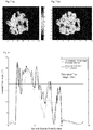
- Fig. 5 (a) is a schematic diagram of inversion results of the ground surface phase obtained by performing line fitting by using the least squares
- Fig. 5 (b) is a schematic diagram of inversion results of the ground surface phase obtained by performing the line fitting by using the total least squares. Since the ground surface phase is set to be a smooth ground surface phase of about 0 when simulation, from the Figs. 5(a) and 5(b) , it can be seen that the ground surface phase obtained by performing the line fitting by using the total least squares is closer to the reality, and the closer to the reality the ground surface phase of an object to be measured is, the higher inversion precision of a forest height obtained ultimately is.
- Fig. 6 is a schematic diagram of a correlation line fitted at the scenario centre point P and a volume scattering decorrelation coefficient.
- a centre of a small square represents a volume scattering decorrelation coefficient estimated by using the inversion method of the disclosure
- a centre of a small circle represents an HV channel correlation coefficient estimated by using the conventional three-stage inversion method.
- Figs. 7(a) and 7(b) show results of forest height estimation obtained respectively by performing inversion according to the conventional three-stage inversion method and by performing inversion according to the method of the disclosure.
- Fig. 7 (a) shows an inversion result of the conventional three-stage inversion method
- Fig. 7 (b) shows an inversion result of the inversion method of the disclosure. From the Figs. 7(a) and 7(b) , it can be seen that tree height values inversed through the inversion method of the disclosure are uniformly distributed in a forest region, while the tree height inversed by the conventional method has a large number of zero value points in the forest region. Thus, the tree height inversion result obtained through the inversion method of the disclosure is closer to the reality.
- the disclosure selects a height inversion result of a scenario azimuth centreline in Fig. 4 (b) to analyze.
- a solid line represents the tree height inversed through the inversion method of the disclosure
- an imaginary line represents the tree height inversed through the conventional three-stage inversion method
- a transverse line represents a theoretical tree height.
- Fig. 9 is a comparison schematic diagram of tree height inversion results of the whole scenario.
- a curve 1 represents the tree height inversion results of the whole scenario obtained by using the inversion method of the disclosure
- a curve 2 represents the tree height inversion results of the whole scenario obtained by using the conventional three-stage inversion method. From the Fig. 9 , it can be seen that the conventional three-stage inversion method may cause the underestimation of the tree height, and the distribution of the tree height value inversed through the inversion method of the disclosure is closer to the theoretical height 18 m. Thus, the inversion method of the disclosure is reliable and effective.
- Table 1 shows comparison results of average errors and root-mean-square errors of tree height inversion obtained respectively through the conventional three-stage inversion method and through the inversion method of the disclosure. From the quantitative comparison, it can be seen that the inversion method of the disclosure improves the precision of the tree height inversion.
- Table 1 Theoretical Tree Height 18 (m) Average Height Root Mean Square Error Average Error Conventional Three-stage Method 15.59 m 6.14 m 5.12 m Inversion Method of the Disclosure 18.64 m 5.12 m 4.96 m
Landscapes
- Engineering & Computer Science (AREA)
- Remote Sensing (AREA)
- Radar, Positioning & Navigation (AREA)
- Physics & Mathematics (AREA)
- Electromagnetism (AREA)
- Computer Networks & Wireless Communication (AREA)
- General Physics & Mathematics (AREA)
- Radar Systems Or Details Thereof (AREA)
- Image Processing (AREA)
Description
- The disclosure relates generally to the application technology of Polarimetric Interferometric Synthetic Aperture Radar (PoLInSAR), and in particular to an inversion method and apparatus based on the PoLInSAR.
- In recent years, inversing forest parameters using PoLInSAR data has been a hot topic. A conventional forest parameter inversion method is a conventional three-stage inversion method proposed by scholars Cloude and Pathanassiou, which is based on an RVOG two-layer vegetation model and divides an inversion process into three steps including: correlation coefficient estimation and line fitting, ground surface phase estimation, and volume scattering decorrelation estimation and parameter estimation. A line fitting error and a volume scattering decorrelation estimation error greatly influence inversion precision.
- During the line fitting of the correlation coefficients, the line fitting error may directly influence the precision of the ground surface phase estimation, and the ground surface phase error directly influences tree height inversion results, thus, the line fitting is a basic step of the three-stage inversion method, and the line fitting error is required to be minimized. At present, the line fitting method generally adopts least squares. The line fitting method adopting the least squares is simple, but there is a defect that only an independent variable error is considered and no dependent variable error is considered, which results in an error in the fitting.
- Theoretically, the volume scattering decorrelation coefficient is a point on a visual line segment of the fitted line which is farthest away from a ground surface phase point. The conventional volume scattering decorrelation coefficient may be approximated to an HV channel correlation coefficient, which however may result in an underestimation of the forest height.
- LULU TAN ET AL: "Improved three-stage inversion process for forest height inversion with PolInSAR data",RADAR (RADAR), 2011 IEEE CIE INTERNATIONAL CONFERENCE ON, IEEE, 24 October 2011 (2011-10-24), pages 1394-1397, XP032124127, discloses an improved three-stage inversion process wherein coherence estimation is performed by adaptive averaging.
- In view of the above, the disclosure provides an inversion method and apparatus based on PoLInSAR, which can improve inversion precision.
- To this end, technical solutions of the disclosure are provided as follows.
- An inversion method based on PoLInSAR, which includes:
- a set of PoLInSAR image data of an object to be measured is acquired, and line fitting is performed, by using total least squares, on a correlation coefficient estimation value acquired from the PoLInSAR image data to determine a ground surface phase estimation value of the object to be measured;
- a volume scattering decorrelation coefficient is acquired through a correlation regional boundary acquired from the PoLInSAR image data and a fitted line; and
- inversion is performed on the object to be measured by establishing a lookup table to acquire an inversion parameter of the object to be measured as a parameter estimation value of the object to be measured;
- the PoLInSAR image data includes four master images and four slave images.
- Preferably, the step that line fitting is performed, by using total least squares, on a correlation coefficient estimation value acquired from the PoLInSAR image data to determine a ground surface phase estimation value of the object to be measured may include:
- line fitting is performed on the correlation coefficient estimation value by using the total least squares to determine a slope estimation value and a slant range estimation value of the fitted line, and the ground surface phase estimation value of the object to be measured is determined according to the slope estimation value and the slant range estimation value.
- Preferably, the step that a volume scattering decorrelation coefficient is acquired through a correlation regional boundary acquired from the PoLInSAR image data and a fitted line may include:
- a correlation regional boundary of the master images and the slave images is determined;
- two intersection points of the fitted line and the correlation regional boundary are determined, and one of the two intersection points which is farther away from the ground surface phase of the object to be measured is determined as a volume scattering decorrelation coefficient.
- Preferably, the step that a correlation regional boundary of the master images and the slave images is determined may include:
- a multiple correlation coefficient of the master images and the slave images is determined according to a scattering mechanism of the master images and the slave images, a polarimetric cross-correlation matrix of the master images and the slave images, and a correlation matrix of the master images and a correlation matrix of the slave images, and the multiple correlation coefficient is corrected;
- a correlation regional boundary is determined through a phase rotation method according to a corrected result of the multiple correlation coefficient.
- Preferably, the step that two intersection points of the fitted line and the correlation regional boundary are determined may include:
- an objective function of the object to be measured is established according to a scattering mechanism of the master images and the slave images, a polarimetric cross-correlation matrix of the master images and the slave images, and a correlation matrix of the master images and a correlation matrix of the slave images, and extreme values of the objective function are determined through a Lagrange multiplier method, the extreme values of the objective function are taken as two intersection points of the fitted line and the correlation regional boundary.
- An apparatus based on PoLInSAR is provided, which includes a ground surface phase determining module, a volume scattering decorrelation coefficient determining module and a parameter determining module.
- The ground surface phase determining module is configured to: acquire a set of PoLInSAR image data of an object to be measured, and perform line fitting, by using total least squares, on a correlation coefficient estimation value acquired from the PoLInSAR image data to determine a ground surface phase estimation value of the object to be measured;
the volume scattering decorrelation coefficient determining module is configured to acquire a volume scattering decorrelation coefficient through a correlation regional boundary acquired from the PoLInSAR image data and a fitted line; and
the parameter determining module is configured to perform inversion on the object to be measured by establishing a lookup table to acquire an inversion parameter of the object to be measured as a parameter estimation value of the object to be measured. - Preferably, the ground surface phase determining module may be further configured to:
- perform line fitting on the correlation coefficient estimation value by using the total least squares to determine a slope estimation value and a slant range estimation value of the fitted line, and determine the ground surface phase estimation value of the object to be measured according to the slope estimation value and the slant range estimation value;
- the PoLInSAR image data includes four master images and four slave images.
- Preferably, the volume scattering decorrelation coefficient determining module may be further configured to:
- determine a correlation regional boundary of the master images and the slave images;
- determine two intersection points of the fitted line and the correlation regional boundary; and
- determine one of the two intersection points which is farther away from the ground surface phase of the object to be measured as a volume scattering decorrelation coefficient.
- Preferably, the volume scattering decorrelation coefficient determining module may be further configured to:
- determine a multiple correlation coefficient of the master images and the slave images according to a scattering mechanism of the master images and the slave images, a polarimetric cross-correlation matrix of the master images and the slave images, and a correlation matrix of the master images and a correlation matrix of the slave images, and correct the multiple correlation coefficient;
- determine a correlation regional boundary through a phase rotation method according to a corrected result of the multiple correlation coefficient.
- Preferably, the parameter determining module may be further configured to: establish an objective function of the object to be measured, according to a scattering mechanism of the master images and the slave images, a polarimetric cross-correlation matrix of the master images and the slave images, and a correlation matrix of the master images and a correlation matrix of the slave images, determine extreme values of the objective function through a Lagrange multiplier method, and take the extreme values of the objective function as two intersection points of the fitted line and the correlation regional boundary.
- According to the inversion method and apparatus based on the PoLInSAR, a set of PoLInSAR image data of an object to be measured is acquired, line fitting is performed, by using total least squares, on a correlation coefficient estimation value acquired from the PoLInSAR image data to determine a ground surface phase estimation value of the object to be measured; a volume scattering decorrelation coefficient is acquired through the correlation regional boundary acquired from the PoLInSAR image data and the fitted line; inversion is performed on the object to be measured by establishing a lookup table to acquire an inversion parameter of the object to be measured as a parameter estimation value of the object to be measured. Thus, the method and apparatus of the disclosure can reduce line fitting error effectively, estimate a volume scattering decorrelation coefficient precisely and then obtain a more precise forest parameter, and accordingly improve the inversion precision of the forest parameter. In addition, the method provided by the disclosure is simple and practicable, and especially applicable to the inversion of forest parameters, an inversion result of tree height can be much closer to the actual height, which is more favourable to a practical application of a remote sensing image. Furthermore, the method provided by the disclosure is simple and practicable, and can perform precise inversion on a crop parameter.
-
-
Fig. 1 is a flow diagram of an inversion method based on PoLInSAR according to the disclosure; -
Fig. 2 is a schematic diagram of volume scattering decorrelation estimation according to the disclosure; -
Fig. 3 is a block diagram of an inversion apparatus based on PoLInSAR according to the disclosure; -
Figs. 4(a) and 4(b) are schematic diagrams of simulation experiment data according to an embodiment of the disclosure; -
Figs. 5(a) and 5(b) are ground surface phase diagrams acquired respectively by using the method of the disclosure and by using a conventional three-stage inversion method according to an embodiment of the disclosure; -
Fig. 6 is a comparison schematic diagram of a volume scattering decorrelation coefficient estimated respectively by using the method of the disclosure and by using the conventional three-stage inversion method according to an embodiment of the disclosure; -
Figs. 7(a) and 7(b) are comparison schematic diagrams of results of tree height inversion performed respectively by using the method of the disclosure and by using the conventional three-stage inversion method according to an embodiment of the disclosure; -
Fig. 8 is a comparison schematic diagram of results of tree height inversion performed on a scenario azimuth centreline respectively by using the method of the disclosure and by using the conventional three-stage inversion method; and -
Fig. 9 is a comparison schematic diagram of results of tree height inversion performed on whole scenario respectively by using the method of the disclosure and by using the conventional three-stage inversion method. - Technical solutions of the disclosure are further elaborated in conjunction with accompanying drawings and specific embodiments.
-
Fig. 1 is a flow diagram of an inversion method based on PoLInSAR according to the disclosure. As shown inFig. 1 , the inversion method may includesteps - In
step 101, a set of PoLInSAR image data of an object to be measured is acquired, and line fitting is performed, by using total least squares, on a correlation coefficient estimation value acquired from the PoLInSAR image data to determine a ground surface phase estimation value of the object to be measured. - The PoLInSAR image data may include four master images and four slave images.
- Specifically, under a polarimetric interferometry condition, polarimetric data of the same object to be measured is acquired by two antennas. A first antenna of the two antennas acquires master image data corresponding to an HH channel, an HV channel, a VH channel and a VV channel respectively, i.e., four master images; a second antenna of the two antennas acquires slave image data corresponding to the HH channel, the HV channel, the VH channel and the VV channel respectively, i.e., four slave images.
- Specifically, the step that line fitting is performed, by using total least squares, on a correlation coefficient estimation value acquired from the PoLInSAR image data to determine a ground surface phase estimation value of the object to be measured may include:
- line fitting is performed on the correlation coefficient estimation value by using the total least squares to determine a slope estimation value and a slant range estimation value of the fitted line, and the ground surface phase estimation value of the object to be measured is determined according to the slope estimation value and the slant range estimation value.
- The correlation coefficient estimation value may include: an HV channel correlation coefficient, an HH channel correlation coefficient, a VV channel correlation coefficient, an RL channel correlation coefficient, an LL channel correlation coefficient, an LR channel correlation coefficient, a
ZU channel 1 correlation coefficient, aZU channel 2 correlation coefficient, and aZU channel 3 correlation coefficient. - The implementation principle and steps of the line fitting performed by using the total least squares are elaborated below:
- A linear equation may be set to be:


- Or the equation (1) may be transformed into a matrix form as the form (B+D)z=0 through an equivalent transformation, where an augmented matrix B is B=[-Y, A], a perturbation matrix D is D=[-EY +EA ], solutions of a homogeneous equation are determined by using total least squares, and this is equivalent to determine a constrained optimization

- Specifically, the step that the line fitting is performed by using the least squares may include:
- Singular Value Decomposition (SVD) is performed on the augmented matrix B to obtain:

- where a matrix V is V=[ν 1,ν 2,...ν n+1], and n+1 eigenvectors of V correspond to n+1 eigenvalues respectively;
- A formula σp >σ n+1+ε≥σ p+1≥···σ n+1 is utilized to determine a number P of the main singular values.
- Assume

ν 1 is the first row vector of V 1, a total least squares solution is determined to be
- After a slope a and slant range b of a fitted line is determined, a ground surface phase estimation value of an object to be measured can be obtained according to a computing method of ground surface phase in the conventional three-stage inversion method proposed by scholar Cloude et al.
- The fitted line intersects with a unit circle at two intersection points, distance between each intersection point and the HV channel and distance between each intersection point and the (HV+VV) channel are calculated, and the intersection point with the distance to the HV channel greater than the distance to the (HV+VV) channel is determined as a ground surface phase estimation value of the object to be measured.
- In
step 102, a volume scattering decorrelation coefficient is acquired through a correlation regional boundary acquired from the PoLInSAR image data and the fitted line. - Specifically, the step that a volume scattering decorrelation coefficient is acquired through a correlation regional boundary acquired from the PoLInSAR image data and the fitted line may include:
- a correlation regional boundary of the master images and the slave images is determined;
- two intersection points of the fitted line and the correlation regional boundary are determined, and one of the two intersection points which is farther away from the ground surface phase of the object to be measured is determined as a volume scattering decorrelation coefficient.
- Specifically, the step that a correlation regional boundary of the master image and the slave image is determined may include:
- a multiple correlation coefficient of the master images and the slave images is determined according to a scattering mechanism of the master images and the slave images, a polarimetric cross-correlation matrix of the master images and the slave images, and a correlation matrix of the master images and a correlation matrix of the slave images; the multiple correlation coefficient of the master images and the slave images is then corrected;
- a correlation regional boundary is determined through a phase rotation method according to a corrected result of the multiple correlation coefficient.
- Specifically, the step that two intersection points of the fitted line and the correlation regional boundary are determined may include:
- an objective function of the object to be measured is established according to the scattering mechanism of the master images and the slave images, the polarimetric cross-correlation matrix of the master images and the slave images, and the correlation matrix of the master images and the correlation matrix of the slave images; extreme values of the objective function is determined through a Lagrange multiplier method, and the extreme values of the objective function are taken as two intersection points of the fitted line and the correlation regional boundary.
- In a practical application, the correlation region refers to distribution region of all multiple correlation coefficients in a complex plane, a shape of which is usually described with a correlation regional boundary. In the disclosure, one of the two intersection points of the fitted line and the correlation regional boundary which is farther away from the ground surface phase is defined as a volume scattering decorrelation coefficient.
- The principle of determining the correlation regional boundary is elaborated below.
- When main and slave channels have the same polarimetric mode, the multiple correlation coefficient under any scattering base is defined as:


- An extreme value of equation (5) can be determined by utilizing the Lagrange multiplier method, a complex Lagrange function is set to be:


- An eigen-decomposition is performed on the matrix -T -1 A to obtain eigenvectors ω 1 and ω 2 corresponding to a maximum eigenvalue and a minimum eigenvalue respectively, and a pair of boundary points of the corresponding correlation region is:

- The correlation regional boundary points can be calculated by rotating φ 0, and the correlation regional boundary has two intersection points with the fitted line obtained in
step 101, and one of the two intersection points which is farther away from the ground surface phase is taken as a volume scattering decorrelation coefficient. - In the conventional three-stage inversion method, an HV channel correlation coefficient is usually taken as a volume scattering decorrelation coefficient, which however may cause underestimation of the parametric inversion.
Fig. 2 is a schematic diagram of volume scattering decorrelation coefficients determined respectively by the method of the disclosure and by the conventional three-stage inversion method for the same object to be measured.Fig. 2 shows that, the volume scattering decorrelation coefficient determined by method of the disclosure is greater than that determined by the conventional three-stage inversion method. Proved by experiments that the method for determining the volume scattering decorrelation coefficient according to the disclosure can overcome, to some extent, the problem of underestimation of the parametric inversion caused by the conventional three-stage inversion method. - In
step 103, inversion is performed on the object to be measured by establishing a lookup table to obtain an inversion parameter of the object to be measured as a parameter estimation value of the object to be measured. - A process of performing parameter estimation by establishing a lookup table is the same as that in the conventional three-stage inversion method.
- For example, taking a forest as the object to be measured: equal interval sampling is performed on tree height from 0 to 30m and a volume scattering decorrelation coefficient is calculated in an ideal condition, a two-dimensional lookup table is established with the equal interval sampling tree height and the calculated volume scattering decorrelation coefficient to perform the parameter estimation, i.e., estimation of forest height of the object to be measured is finished.
-
Fig. 3 is a block diagram of an inversion apparatus based on PoLInSAR according to the disclosure. As shown inFig. 3 , the inversion apparatus includes a ground surfacephase determining module 31, a volume scattering decorrelationcoefficient determining module 32 and aparameter determining module 33. - The ground surface
phase determining module 31 is configured to: acquire a set of PoLInSAR image data of an object to be measured, and perform line fitting, by using total least squares, on a correlation coefficient estimation value acquired from the PoLInSAR image data to determine a ground surface phase estimation value of the object to be measured. - The volume scattering decorrelation
coefficient determining module 32 is configured to acquire a volume scattering decorrelation coefficient through a correlation regional boundary acquired from the PoLInSAR image data and a fitted line. - The
parameter determining module 33 is configured to perform inversion on the object to be measured by establishing a lookup table to acquire an inversion parameter of the object to be measured as a parameter estimation value of the object to be measured. - Specifically, the ground surface
phase determining module 31 may be further configured to: perform line fitting on the correlation coefficient estimation value by using the total least squares to determine a slope estimation value and a slant range estimation value of the fitted line, and determine the ground surface phase estimation value of the object to be measured according to the slope estimation value and the slant range estimation value. - Specifically, the volume scattering decorrelation
coefficient determining module 32 may be further configured to: - determine a correlation regional boundary of the master image and the slave image;
- determine two intersection points of the fitted line and the correlation regional boundary, and determine one of the two intersection points which is farther away from the ground surface phase of the object to be measured as a volume scattering decorrelation coefficient.
- Specifically, the volume scattering decorrelation
coefficient determining module 32 may be further configured to: - determine a multiple correlation coefficient of the master images and the slave images, according to a scattering mechanism of the master image and the slave image, the polarimetric cross-correlation matrix of the master image and the slave image, and a correlation matrix of the master image and a correlation matrix of the slave image, and correct the multiple correlation coefficient of the master images and the slave images;
- determine a correlation regional boundary through a phase rotation method according to a corrected result of the multiple correlation coefficient.
- The
parameter determining module 33 may be further configured to: establish an objective function of the object to be measured, according to the scattering mechanism of the master images and the slave images, the polarimetric cross-correlation matrix of the master images and the slave images, the correlation matrix of the master images and the correlation matrix of the slave images, determine extreme values of the objective function through a Lagrange multiplier method, and take the extreme values of the objective function as two intersection points of the fitted line and the correlation regional boundary. - Those skilled in the art should understand that the implementation function of each processing module in the inversion apparatus based on PoLInSAR shown in
Fig. 3 can be understood by reference to the above relevant description of an inversion method based on PoLInSAR. Those skilled in the art should understand that functions of each processing unit in the inversion apparatus based on the PoLInSAR shown inFig. 3 can be implemented through a program running on a processor, also can be implemented through specific logical circuits. - In order to better illustrate the effect of the inversion method of the disclosure, the following will describe the inversion of tree height taken as an example of the object to be measured.
- In this embodiment, a set of PoLInSAR image data of L band generated by a PolSARpro software provided by the European Space Agency is adopted to verify the inversion method of the disclosure. Simulation parameters of the PolSARpro software include: a platform height 3000 m, a vertical baseline 1 m, a horizontal baseline 10 m, an incident angle π/2, a centre frequency 1.3 GHZ, a tree height 18 m, a ground surface being a smooth ground surface phase with phase of about 0, and an image size 105x141 pixels.
Fig. 4 (a) is a composite graph of selected Pauli bases, and inFig. 4 (b) , a point marked by a small circle is denoted by P, and the point P is a scenario centre point. -
Figs. 5(a) and 5(b) are schematic diagrams of a ground surface phase.Fig. 5 (a) is a schematic diagram of inversion results of the ground surface phase obtained by performing line fitting by using the least squares, andFig. 5 (b) is a schematic diagram of inversion results of the ground surface phase obtained by performing the line fitting by using the total least squares. Since the ground surface phase is set to be a smooth ground surface phase of about 0 when simulation, from theFigs. 5(a) and 5(b) , it can be seen that the ground surface phase obtained by performing the line fitting by using the total least squares is closer to the reality, and the closer to the reality the ground surface phase of an object to be measured is, the higher inversion precision of a forest height obtained ultimately is. -
Fig. 6 is a schematic diagram of a correlation line fitted at the scenario centre point P and a volume scattering decorrelation coefficient. InFig.6 , a centre of a small square represents a volume scattering decorrelation coefficient estimated by using the inversion method of the disclosure, and a centre of a small circle represents an HV channel correlation coefficient estimated by using the conventional three-stage inversion method. From theFig. 6 , it can be seen that an estimation value of the volume scattering decorrelation coefficient obtained by using the inversion method of the disclosure is farther from the ground surface phase than the HV channel correlation coefficient value, thus, the inversion method of the disclosure can overcome to some extent the problem of the underestimation of forest height caused by using the conventional three-stage inversion method. -
Figs. 7(a) and 7(b) show results of forest height estimation obtained respectively by performing inversion according to the conventional three-stage inversion method and by performing inversion according to the method of the disclosure.Fig. 7 (a) shows an inversion result of the conventional three-stage inversion method, andFig. 7 (b) shows an inversion result of the inversion method of the disclosure. From theFigs. 7(a) and 7(b) , it can be seen that tree height values inversed through the inversion method of the disclosure are uniformly distributed in a forest region, while the tree height inversed by the conventional method has a large number of zero value points in the forest region. Thus, the tree height inversion result obtained through the inversion method of the disclosure is closer to the reality. - In order to verify the feasibility of the inversion method of the disclosure more effectively, the disclosure selects a height inversion result of a scenario azimuth centreline in
Fig. 4 (b) to analyze. As shown inFig. 8 , a solid line represents the tree height inversed through the inversion method of the disclosure, an imaginary line represents the tree height inversed through the conventional three-stage inversion method, and a transverse line represents a theoretical tree height. Obviously, it can be seen from theFig. 8 that the inversion method of the disclosure can overcome to some extent the problem of the underestimation of the tree height caused by using the conventional three-stage inversion method. -
Fig. 9 is a comparison schematic diagram of tree height inversion results of the whole scenario. InFig. 9 , acurve 1 represents the tree height inversion results of the whole scenario obtained by using the inversion method of the disclosure, while acurve 2 represents the tree height inversion results of the whole scenario obtained by using the conventional three-stage inversion method. From theFig. 9 , it can be seen that the conventional three-stage inversion method may cause the underestimation of the tree height, and the distribution of the tree height value inversed through the inversion method of the disclosure is closer to the theoretical height 18 m. Thus, the inversion method of the disclosure is reliable and effective. - For comparing the inversion method of the disclosure with the conventional three-stage inversion method more vividly, a quantitative analysis may be performed on a tree height inversion result. Table 1 shows comparison results of average errors and root-mean-square errors of tree height inversion obtained respectively through the conventional three-stage inversion method and through the inversion method of the disclosure. From the quantitative comparison, it can be seen that the inversion method of the disclosure improves the precision of the tree height inversion.
Table 1 Theoretical Tree Height 18 (m) Average Height Root Mean Square Error Average Error Conventional Three-stage Method 15.59 m 6.14 m 5.12 m Inversion Method of the Disclosure 18.64 m 5.12 m 4.96 m - Experiment results indicate that the method of the disclosure is particularly applicable to the estimation of a forest parameter. In addition, the method of the disclosure is further applicable to application scenarios such as crop parameter estimation.
- The above mentioned are only the preferable embodiments of the disclosure, and are not intended to limit the scope of the disclosure.
Claims (10)
- An inversion method based on Polarimetric Interferometric Synthetic Aperture Radar, PoLInSAR, comprising:acquiring a set of PoLInSAR image data of an object to be measured, and performing line fitting, by using total least squares, on a correlation coefficient estimation value acquired from the PoLInSAR image data to determine a ground surface phase estimation value of the object to be measured (101);acquiring a volume scattering decorrelation coefficient through a correlation regional boundary acquired from the PoLInSAR image data and a fitted line (102); andperforming inversion on the object to be measured by establishing a lookup table, to acquire an inversion parameter of the object to be measured as a parameter estimation value of the object to be measured (103);wherein, the PoLInSAR image data comprises four master images and four slave images.
- The method according to claim 1, wherein the step of performing line fitting, by using total least squares, on a correlation coefficient estimation value acquired from the PoLInSAR image data to determine a ground surface phase estimation value of the object to be measured comprises:performing line fitting on the correlation coefficient estimation value by using the total least squares to determine a slope estimation value and a slant range estimation value of the fitted line, and determining the ground surface phase estimation value of the object to be measured according to the slope estimation value and the slant range estimation value.
- The method according to claim 1, wherein the step of acquiring a volume scattering decorrelation coefficient through a correlation regional boundary acquired from the PoLInSAR image data and a fitted line comprises:determining a correlation regional boundary of the master images and the slave images;determining two intersection points of the fitted line and the correlation regional boundary; anddetermining one of the two intersection points which is farther away from the ground surface phase of the object to be measured as a volume scattering decorrelation coefficient.
- The method according to claim 3, wherein the step of determining a correlation regional boundary of the mains image and the slave images comprises:determining a multiple correlation coefficient of the master images and the slave images according to a scattering mechanism of the master images and the slave images, a polarimetric cross-correlation matrix of the master images and the slave images, and a correlation matrix of the master images and a correlation matrix of the slave images;correcting the multiple correlation coefficient; anddetermining the correlation regional boundary through a phase rotation method according to a corrected result of the multiple correlation coefficient.
- The method according to claim 3, wherein the step of determining two intersection points of the fitted line and the correlation regional boundary comprises:establishing an objective function of the object to be measured, according to a scattering mechanism of the master images and the slave images, a polarimetric cross-correlation matrix of the master images and the slave image, and a correlation matrix of the master images and a correlation matrix of the slave images;determining extreme values of the objective function through a Lagrange multiplier method; andtaking the extreme values of the objective function as the two intersection points of the fitted line and the correlation regional boundary.
- An inversion apparatus based on Polarimetric Interferometric Synthetic Aperture Radar, PoLInSAR, comprising a ground surface phase determining module (31), a volume
scattering decorrelation coefficient determining module (32) and a parameter determining module (33), wherein
the ground surface phase determining module (31) is configured to: acquire a set of
PoLInSAR image data of an object to be measured, and perform line fitting, by using total least squares, on a correlation coefficient estimation value acquired from the PoLInSAR image data to determine a ground surface phase estimation value of the object to be measured;
the volume scattering decorrelation coefficient determining module (32) is configured to
acquire a volume scattering decorrelation coefficient through a correlation regional boundary acquired from the PoLInSAR image data and a fitted line; and
the parameter determining modules is configured to perform inversion on the object
to be measured by establishing a lookup table to acquire an inversion parameter of the object to be measured as a parameter estimation value of the object to be measured. - The apparatus according to claim 6, wherein the ground surface phase determining module is further configured to:perform line fitting on the correlation coefficient estimation value by using the total least squares to determine a slope estimation value and a slant range estimation value of the fitted line; anddetermine the ground surface phase estimation value of the object to be measured according to the slope estimation value and the slant range estimation value;wherein the PoLInSAR image data comprises four master images and four slave images.
- The apparatus according to claim 6, wherein the volume scattering decorrelation coefficient determining module is further configured to:determine a correlation regional boundary of the master images and the slave images;determine two intersection points of the fitted line and the correlation regional boundary; anddetermine one of the two intersection points which is farther away from the ground surface phase of the object to be measured as a volume scattering decorrelation coefficient.
- The apparatus according to claim 6, wherein the volume scattering decorrelation coefficient determining module is further configured to:determine a multiple correlation coefficient of the master images and the slave images according to a scattering mechanism of the master images and the slave images, a polarimetric cross-correlation matrix of the master images and the slave images, and a correlation matrix of the master images and a correlation matrix of the slave images;correct the multiple correlation coefficient; anddetermine a correlation regional boundary through a phase rotation method according to a corrected result of the multiple correlation coefficient.
- The apparatus according to claim 6, wherein the parameter determining module is further configured to:establish an objective function of the object to be measured, according to a scattering mechanism of the master images and the slave images, a polarimetric cross-correlation matrix of the master images and the slave images, and a correlation matrix of the master images and a correlation matrix of the slave images;determine extreme values of the objective function through a Lagrange multiplier method; andtake the extreme values of the objective function as two intersection points of the fitted line and the correlation regional boundary.
Applications Claiming Priority (1)
| Application Number | Priority Date | Filing Date | Title |
|---|---|---|---|
| CN201310180311.6A CN103323846B (en) | 2013-05-15 | 2013-05-15 | A kind of inversion method based on polarization interference synthetic aperture radar and device |
Publications (2)
| Publication Number | Publication Date |
|---|---|
| EP2784537A1 EP2784537A1 (en) | 2014-10-01 |
| EP2784537B1 true EP2784537B1 (en) | 2016-10-19 |
Family
ID=49192698
Family Applications (1)
| Application Number | Title | Priority Date | Filing Date |
|---|---|---|---|
| EP14162311.6A Not-in-force EP2784537B1 (en) | 2013-05-15 | 2014-03-28 | Inversion method and apparatus based on polarimetric interferometric synthetic aperture radar |
Country Status (2)
| Country | Link |
|---|---|
| EP (1) | EP2784537B1 (en) |
| CN (1) | CN103323846B (en) |
Cited By (7)
| Publication number | Priority date | Publication date | Assignee | Title |
|---|---|---|---|---|
| US10230925B2 (en) | 2014-06-13 | 2019-03-12 | Urthecast Corp. | Systems and methods for processing and providing terrestrial and/or space-based earth observation video |
| US10615513B2 (en) | 2015-06-16 | 2020-04-07 | Urthecast Corp | Efficient planar phased array antenna assembly |
| US10871561B2 (en) | 2015-03-25 | 2020-12-22 | Urthecast Corp. | Apparatus and methods for synthetic aperture radar with digital beamforming |
| US10955546B2 (en) | 2015-11-25 | 2021-03-23 | Urthecast Corp. | Synthetic aperture radar imaging apparatus and methods |
| US11378682B2 (en) | 2017-05-23 | 2022-07-05 | Spacealpha Insights Corp. | Synthetic aperture radar imaging apparatus and methods for moving targets |
| US11506778B2 (en) | 2017-05-23 | 2022-11-22 | Spacealpha Insights Corp. | Synthetic aperture radar imaging apparatus and methods |
| US11525910B2 (en) | 2017-11-22 | 2022-12-13 | Spacealpha Insights Corp. | Synthetic aperture radar apparatus and methods |
Families Citing this family (21)
| Publication number | Priority date | Publication date | Assignee | Title |
|---|---|---|---|---|
| CN103760565A (en) * | 2014-02-10 | 2014-04-30 | 中国科学院南京地理与湖泊研究所 | Regional scale forest canopy height remote sensing retrieval method |
| CN104808203B (en) * | 2015-03-03 | 2017-05-10 | 电子科技大学 | An Iterative Maximum Likelihood Estimation Method for Multi-Baseline InSAR Phase Unwrapping |
| CN105372655A (en) * | 2015-10-30 | 2016-03-02 | 湖南科技大学 | Earth's surface backward scattering coefficient indoor determination device and application method thereof |
| CN108509836B (en) * | 2018-01-29 | 2021-10-08 | 中国农业大学 | Crop Yield Estimation Method Based on Data Assimilation of Dual Polarization Synthetic Aperture Radar and Crop Model |
| CN110109111B (en) * | 2019-04-28 | 2023-02-10 | 西安电子科技大学 | Sparse Vegetation Height Retrieval Method for Polarimetric Interferometric SAR |
| CN110244301A (en) * | 2019-06-27 | 2019-09-17 | 国网四川省电力公司电力科学研究院 | A kind of high extracting method of transmission of electricity corridor tree based on SAR image |
| CN110441767A (en) * | 2019-09-06 | 2019-11-12 | 云南电网有限责任公司电力科学研究院 | Method and system for measuring the clearance height of tree barriers in transmission line corridors |
| CN111398957B (en) * | 2020-04-01 | 2022-08-02 | 中国林业科学研究院资源信息研究所 | Short-wavelength double-antenna InSAR forest height inversion method for improving coherence calculation method |
| CN111553421B (en) * | 2020-04-28 | 2022-03-08 | 电子科技大学 | SAR equipment task failure cause reasoning method based on double-layer nested structure |
| CN112363161B (en) * | 2020-10-27 | 2022-12-20 | 中南大学 | Vegetation vertical structure and under-forest topography inversion method and device based on scattering mechanism decomposition |
| CN112882026B (en) * | 2021-01-11 | 2023-04-11 | 清华大学 | Tree height inversion method and device, computer storage medium and terminal |
| CN113376629B (en) * | 2021-05-13 | 2022-08-05 | 电子科技大学 | Inversion method of borehole radar least squares based on non-uniform input parameter grid |
| CN113945927B (en) * | 2021-09-17 | 2022-09-06 | 西南林业大学 | A method for inversion of forest canopy height optimized by volume scattering |
| CN113945926B (en) * | 2021-09-17 | 2022-07-08 | 西南林业大学 | Forest canopy height inversion method improved through underestimation compensation |
| CN114252480B (en) * | 2021-12-21 | 2024-09-24 | 中南大学 | Method for inverting soil humidity of bare soil area based on single polarization SAR data neighborhood pixels |
| CN114594475B (en) * | 2022-03-15 | 2025-02-11 | 中国自然资源航空物探遥感中心 | Decomposition method of π/4 reduced polarimetric interferometric synthetic aperture radar |
| CN115993601B (en) * | 2023-03-22 | 2023-06-09 | 四川省公路规划勘察设计研究院有限公司 | Time sequence InSAR monitoring method for highway deformation in strong saline soil region |
| CN117077547B (en) * | 2023-10-16 | 2023-12-26 | 西南林业大学 | Forest overground biomass estimation method and system |
| CN117452432B (en) * | 2023-12-21 | 2024-03-15 | 西南林业大学 | Forest canopy height estimation method based on forest penetration compensation |
| CN118366059A (en) * | 2024-06-20 | 2024-07-19 | 山东锋士信息技术有限公司 | A method for calculating crop water requirement based on optical and SAR data fusion |
| CN119380135B (en) * | 2024-10-08 | 2025-09-26 | 中国科学院新疆生态与地理研究所 | A hydrogeological parameter inversion method and system based on time-series InSAR |
Family Cites Families (3)
| Publication number | Priority date | Publication date | Assignee | Title |
|---|---|---|---|---|
| CN101770026B (en) * | 2009-01-07 | 2012-01-25 | 中国科学院电子学研究所 | Method for estimating terrain by polarization interference of data of synthetic aperture radar |
| ES2384922B1 (en) * | 2010-06-07 | 2013-06-11 | Universitat Politècnica De Catalunya | PROCEDURE FOR ESTIMATING THE TOPOGRAPHY OF THE EARTH'S SURFACE IN AREAS WITH PLANT COVERAGE. |
| GB2482551A (en) * | 2010-08-06 | 2012-02-08 | Qinetiq Ltd | Alignment of synthetic aperture radar images |
-
2013
- 2013-05-15 CN CN201310180311.6A patent/CN103323846B/en active Active
-
2014
- 2014-03-28 EP EP14162311.6A patent/EP2784537B1/en not_active Not-in-force
Non-Patent Citations (1)
| Title |
|---|
| None * |
Cited By (8)
| Publication number | Priority date | Publication date | Assignee | Title |
|---|---|---|---|---|
| US10230925B2 (en) | 2014-06-13 | 2019-03-12 | Urthecast Corp. | Systems and methods for processing and providing terrestrial and/or space-based earth observation video |
| US10871561B2 (en) | 2015-03-25 | 2020-12-22 | Urthecast Corp. | Apparatus and methods for synthetic aperture radar with digital beamforming |
| US10615513B2 (en) | 2015-06-16 | 2020-04-07 | Urthecast Corp | Efficient planar phased array antenna assembly |
| US10955546B2 (en) | 2015-11-25 | 2021-03-23 | Urthecast Corp. | Synthetic aperture radar imaging apparatus and methods |
| US11754703B2 (en) | 2015-11-25 | 2023-09-12 | Spacealpha Insights Corp. | Synthetic aperture radar imaging apparatus and methods |
| US11378682B2 (en) | 2017-05-23 | 2022-07-05 | Spacealpha Insights Corp. | Synthetic aperture radar imaging apparatus and methods for moving targets |
| US11506778B2 (en) | 2017-05-23 | 2022-11-22 | Spacealpha Insights Corp. | Synthetic aperture radar imaging apparatus and methods |
| US11525910B2 (en) | 2017-11-22 | 2022-12-13 | Spacealpha Insights Corp. | Synthetic aperture radar apparatus and methods |
Also Published As
| Publication number | Publication date |
|---|---|
| EP2784537A1 (en) | 2014-10-01 |
| CN103323846A (en) | 2013-09-25 |
| CN103323846B (en) | 2015-08-19 |
Similar Documents
| Publication | Publication Date | Title |
|---|---|---|
| EP2784537A1 (en) | Inversion method and apparatus based on polarimetric interferometric synthetic aperture radar | |
| CN106405547B (en) | A kind of multipolarization SAR condenses polarization mode calibrating method | |
| CN104020469B (en) | A kind of MIMO radar distance-angle two-dimensional super-resolution rate imaging algorithm | |
| CN107144842A (en) | A kind of improved polarimetric SAR interferometry vegetation height joint inversion method | |
| CN110146857B (en) | Estimation method for three-dimensional motion error of bump platform SAR | |
| CN103235301A (en) | Polarimetric synthetic aperture radar interferometry (POLInSAR) vegetation height inversion method based on complex field adjustment theory | |
| CN108051810A (en) | A kind of InSAR distributed diffusions body phase optimization method | |
| DE112015006123T5 (en) | Processing device for signals of a synthetic aperture radar | |
| CN115060208A (en) | Power transmission and transformation line geological disaster monitoring method and system based on multi-source satellite fusion | |
| CN104881866A (en) | Fisheye camera rectification and calibration method for expanding pin-hole imaging model | |
| CN107561534A (en) | A kind of ionosphere time-varying TEC measuring methods based on the high rail SAR of complete polarization | |
| CN111766577B (en) | Power transmission line channel tree height inversion method based on three-stage algorithm P wave band | |
| Chen et al. | Enhanced 3-D building layout tomographic imaging via tensor approach | |
| CN110940638A (en) | Hyperspectral image sub-pixel level water body boundary detection method and detection system | |
| CN101608914A (en) | RPC parameter optimization method based on multicollinearity analysis | |
| Kong et al. | Polar motion prediction using the combination of SSA and ARMA | |
| CN106168665A (en) | A kind of scanning radar self adaptation angle based on regularization ultra-resolution method | |
| CN105956622A (en) | Polarized SAR image classification method based on multi-characteristic combined modeling | |
| CN102495407B (en) | Characterization method of similarity of polarized synthetic aperture radar image | |
| US8892383B2 (en) | Calibration device | |
| CN105044660A (en) | Rapid correction method of array channel inconsistency error | |
| CN110471030A (en) | Based on the radio frequency tomography passive type Position-Solving method for improving conjugate gradient | |
| Hadj-Rabah et al. | Covariance based approach using expectation maximization algorithm for forest height estimation | |
| CN109544521A (en) | The method for registering of passive millimeter wave image and visible images in a kind of human body safety check | |
| CN120507754B (en) | High-efficiency super-resolution imaging method and device for tomographic synthetic aperture radar |
Legal Events
| Date | Code | Title | Description |
|---|---|---|---|
| 17P | Request for examination filed |
Effective date: 20140328 |
|
| AK | Designated contracting states |
Kind code of ref document: A1 Designated state(s): AL AT BE BG CH CY CZ DE DK EE ES FI FR GB GR HR HU IE IS IT LI LT LU LV MC MK MT NL NO PL PT RO RS SE SI SK SM TR |
|
| AX | Request for extension of the european patent |
Extension state: BA ME |
|
| PUAI | Public reference made under article 153(3) epc to a published international application that has entered the european phase |
Free format text: ORIGINAL CODE: 0009012 |
|
| RIN1 | Information on inventor provided before grant (corrected) |
Inventor name: ZHAO, FENGJUN Inventor name: XU, LIYING Inventor name: DENG, YUNKAI Inventor name: WANG, YU Inventor name: NI, JIANG Inventor name: ZHANG, ZHIMIN Inventor name: WANG, CHUNLE Inventor name: YU, WEIDONG |
|
| GRAP | Despatch of communication of intention to grant a patent |
Free format text: ORIGINAL CODE: EPIDOSNIGR1 |
|
| INTG | Intention to grant announced |
Effective date: 20160711 |
|
| GRAS | Grant fee paid |
Free format text: ORIGINAL CODE: EPIDOSNIGR3 |
|
| GRAA | (expected) grant |
Free format text: ORIGINAL CODE: 0009210 |
|
| AK | Designated contracting states |
Kind code of ref document: B1 Designated state(s): AL AT BE BG CH CY CZ DE DK EE ES FI FR GB GR HR HU IE IS IT LI LT LU LV MC MK MT NL NO PL PT RO RS SE SI SK SM TR |
|
| REG | Reference to a national code |
Ref country code: GB Ref legal event code: FG4D |
|
| REG | Reference to a national code |
Ref country code: CH Ref legal event code: EP |
|
| REG | Reference to a national code |
Ref country code: AT Ref legal event code: REF Ref document number: 838804 Country of ref document: AT Kind code of ref document: T Effective date: 20161115 |
|
| REG | Reference to a national code |
Ref country code: IE Ref legal event code: FG4D |
|
| REG | Reference to a national code |
Ref country code: DE Ref legal event code: R096 Ref document number: 602014004291 Country of ref document: DE |
|
| REG | Reference to a national code |
Ref country code: NL Ref legal event code: MP Effective date: 20161019 |
|
| REG | Reference to a national code |
Ref country code: LT Ref legal event code: MG4D |
|
| PG25 | Lapsed in a contracting state [announced via postgrant information from national office to epo] |
Ref country code: LV Free format text: LAPSE BECAUSE OF FAILURE TO SUBMIT A TRANSLATION OF THE DESCRIPTION OR TO PAY THE FEE WITHIN THE PRESCRIBED TIME-LIMIT Effective date: 20161019 |
|
| REG | Reference to a national code |
Ref country code: AT Ref legal event code: MK05 Ref document number: 838804 Country of ref document: AT Kind code of ref document: T Effective date: 20161019 |
|
| PG25 | Lapsed in a contracting state [announced via postgrant information from national office to epo] |
Ref country code: GR Free format text: LAPSE BECAUSE OF FAILURE TO SUBMIT A TRANSLATION OF THE DESCRIPTION OR TO PAY THE FEE WITHIN THE PRESCRIBED TIME-LIMIT Effective date: 20170120 Ref country code: NO Free format text: LAPSE BECAUSE OF FAILURE TO SUBMIT A TRANSLATION OF THE DESCRIPTION OR TO PAY THE FEE WITHIN THE PRESCRIBED TIME-LIMIT Effective date: 20170119 Ref country code: SE Free format text: LAPSE BECAUSE OF FAILURE TO SUBMIT A TRANSLATION OF THE DESCRIPTION OR TO PAY THE FEE WITHIN THE PRESCRIBED TIME-LIMIT Effective date: 20161019 Ref country code: LT Free format text: LAPSE BECAUSE OF FAILURE TO SUBMIT A TRANSLATION OF THE DESCRIPTION OR TO PAY THE FEE WITHIN THE PRESCRIBED TIME-LIMIT Effective date: 20161019 |
|
| PG25 | Lapsed in a contracting state [announced via postgrant information from national office to epo] |
Ref country code: PT Free format text: LAPSE BECAUSE OF FAILURE TO SUBMIT A TRANSLATION OF THE DESCRIPTION OR TO PAY THE FEE WITHIN THE PRESCRIBED TIME-LIMIT Effective date: 20170220 Ref country code: NL Free format text: LAPSE BECAUSE OF FAILURE TO SUBMIT A TRANSLATION OF THE DESCRIPTION OR TO PAY THE FEE WITHIN THE PRESCRIBED TIME-LIMIT Effective date: 20161019 Ref country code: PL Free format text: LAPSE BECAUSE OF FAILURE TO SUBMIT A TRANSLATION OF THE DESCRIPTION OR TO PAY THE FEE WITHIN THE PRESCRIBED TIME-LIMIT Effective date: 20161019 Ref country code: BE Free format text: LAPSE BECAUSE OF FAILURE TO SUBMIT A TRANSLATION OF THE DESCRIPTION OR TO PAY THE FEE WITHIN THE PRESCRIBED TIME-LIMIT Effective date: 20161019 Ref country code: RS Free format text: LAPSE BECAUSE OF FAILURE TO SUBMIT A TRANSLATION OF THE DESCRIPTION OR TO PAY THE FEE WITHIN THE PRESCRIBED TIME-LIMIT Effective date: 20161019 Ref country code: IS Free format text: LAPSE BECAUSE OF FAILURE TO SUBMIT A TRANSLATION OF THE DESCRIPTION OR TO PAY THE FEE WITHIN THE PRESCRIBED TIME-LIMIT Effective date: 20170219 Ref country code: FI Free format text: LAPSE BECAUSE OF FAILURE TO SUBMIT A TRANSLATION OF THE DESCRIPTION OR TO PAY THE FEE WITHIN THE PRESCRIBED TIME-LIMIT Effective date: 20161019 Ref country code: HR Free format text: LAPSE BECAUSE OF FAILURE TO SUBMIT A TRANSLATION OF THE DESCRIPTION OR TO PAY THE FEE WITHIN THE PRESCRIBED TIME-LIMIT Effective date: 20161019 Ref country code: ES Free format text: LAPSE BECAUSE OF FAILURE TO SUBMIT A TRANSLATION OF THE DESCRIPTION OR TO PAY THE FEE WITHIN THE PRESCRIBED TIME-LIMIT Effective date: 20161019 Ref country code: AT Free format text: LAPSE BECAUSE OF FAILURE TO SUBMIT A TRANSLATION OF THE DESCRIPTION OR TO PAY THE FEE WITHIN THE PRESCRIBED TIME-LIMIT Effective date: 20161019 |
|
| REG | Reference to a national code |
Ref country code: DE Ref legal event code: R097 Ref document number: 602014004291 Country of ref document: DE |
|
| PG25 | Lapsed in a contracting state [announced via postgrant information from national office to epo] |
Ref country code: CZ Free format text: LAPSE BECAUSE OF FAILURE TO SUBMIT A TRANSLATION OF THE DESCRIPTION OR TO PAY THE FEE WITHIN THE PRESCRIBED TIME-LIMIT Effective date: 20161019 Ref country code: EE Free format text: LAPSE BECAUSE OF FAILURE TO SUBMIT A TRANSLATION OF THE DESCRIPTION OR TO PAY THE FEE WITHIN THE PRESCRIBED TIME-LIMIT Effective date: 20161019 Ref country code: RO Free format text: LAPSE BECAUSE OF FAILURE TO SUBMIT A TRANSLATION OF THE DESCRIPTION OR TO PAY THE FEE WITHIN THE PRESCRIBED TIME-LIMIT Effective date: 20161019 Ref country code: DK Free format text: LAPSE BECAUSE OF FAILURE TO SUBMIT A TRANSLATION OF THE DESCRIPTION OR TO PAY THE FEE WITHIN THE PRESCRIBED TIME-LIMIT Effective date: 20161019 Ref country code: SK Free format text: LAPSE BECAUSE OF FAILURE TO SUBMIT A TRANSLATION OF THE DESCRIPTION OR TO PAY THE FEE WITHIN THE PRESCRIBED TIME-LIMIT Effective date: 20161019 |
|
| PLBE | No opposition filed within time limit |
Free format text: ORIGINAL CODE: 0009261 |
|
| STAA | Information on the status of an ep patent application or granted ep patent |
Free format text: STATUS: NO OPPOSITION FILED WITHIN TIME LIMIT |
|
| PG25 | Lapsed in a contracting state [announced via postgrant information from national office to epo] |
Ref country code: SM Free format text: LAPSE BECAUSE OF FAILURE TO SUBMIT A TRANSLATION OF THE DESCRIPTION OR TO PAY THE FEE WITHIN THE PRESCRIBED TIME-LIMIT Effective date: 20161019 Ref country code: BG Free format text: LAPSE BECAUSE OF FAILURE TO SUBMIT A TRANSLATION OF THE DESCRIPTION OR TO PAY THE FEE WITHIN THE PRESCRIBED TIME-LIMIT Effective date: 20170119 Ref country code: IT Free format text: LAPSE BECAUSE OF FAILURE TO SUBMIT A TRANSLATION OF THE DESCRIPTION OR TO PAY THE FEE WITHIN THE PRESCRIBED TIME-LIMIT Effective date: 20161019 |
|
| 26N | No opposition filed |
Effective date: 20170720 |
|
| REG | Reference to a national code |
Ref country code: DE Ref legal event code: R119 Ref document number: 602014004291 Country of ref document: DE |
|
| REG | Reference to a national code |
Ref country code: CH Ref legal event code: PL |
|
| PG25 | Lapsed in a contracting state [announced via postgrant information from national office to epo] |
Ref country code: SI Free format text: LAPSE BECAUSE OF FAILURE TO SUBMIT A TRANSLATION OF THE DESCRIPTION OR TO PAY THE FEE WITHIN THE PRESCRIBED TIME-LIMIT Effective date: 20161019 Ref country code: MC Free format text: LAPSE BECAUSE OF FAILURE TO SUBMIT A TRANSLATION OF THE DESCRIPTION OR TO PAY THE FEE WITHIN THE PRESCRIBED TIME-LIMIT Effective date: 20161019 |
|
| REG | Reference to a national code |
Ref country code: IE Ref legal event code: MM4A |
|
| REG | Reference to a national code |
Ref country code: FR Ref legal event code: ST Effective date: 20171130 |
|
| PG25 | Lapsed in a contracting state [announced via postgrant information from national office to epo] |
Ref country code: DE Free format text: LAPSE BECAUSE OF NON-PAYMENT OF DUE FEES Effective date: 20171003 Ref country code: FR Free format text: LAPSE BECAUSE OF NON-PAYMENT OF DUE FEES Effective date: 20170331 Ref country code: LU Free format text: LAPSE BECAUSE OF NON-PAYMENT OF DUE FEES Effective date: 20170328 |
|
| PG25 | Lapsed in a contracting state [announced via postgrant information from national office to epo] |
Ref country code: CH Free format text: LAPSE BECAUSE OF NON-PAYMENT OF DUE FEES Effective date: 20170331 Ref country code: IE Free format text: LAPSE BECAUSE OF NON-PAYMENT OF DUE FEES Effective date: 20170328 Ref country code: LI Free format text: LAPSE BECAUSE OF NON-PAYMENT OF DUE FEES Effective date: 20170331 |
|
| PG25 | Lapsed in a contracting state [announced via postgrant information from national office to epo] |
Ref country code: MT Free format text: LAPSE BECAUSE OF NON-PAYMENT OF DUE FEES Effective date: 20170328 |
|
| GBPC | Gb: european patent ceased through non-payment of renewal fee |
Effective date: 20180328 |
|
| PG25 | Lapsed in a contracting state [announced via postgrant information from national office to epo] |
Ref country code: GB Free format text: LAPSE BECAUSE OF NON-PAYMENT OF DUE FEES Effective date: 20180328 |
|
| PG25 | Lapsed in a contracting state [announced via postgrant information from national office to epo] |
Ref country code: HU Free format text: LAPSE BECAUSE OF FAILURE TO SUBMIT A TRANSLATION OF THE DESCRIPTION OR TO PAY THE FEE WITHIN THE PRESCRIBED TIME-LIMIT; INVALID AB INITIO Effective date: 20140328 |
|
| PG25 | Lapsed in a contracting state [announced via postgrant information from national office to epo] |
Ref country code: CY Free format text: LAPSE BECAUSE OF FAILURE TO SUBMIT A TRANSLATION OF THE DESCRIPTION OR TO PAY THE FEE WITHIN THE PRESCRIBED TIME-LIMIT Effective date: 20161019 |
|
| PG25 | Lapsed in a contracting state [announced via postgrant information from national office to epo] |
Ref country code: MK Free format text: LAPSE BECAUSE OF FAILURE TO SUBMIT A TRANSLATION OF THE DESCRIPTION OR TO PAY THE FEE WITHIN THE PRESCRIBED TIME-LIMIT Effective date: 20161019 |
|
| PG25 | Lapsed in a contracting state [announced via postgrant information from national office to epo] |
Ref country code: TR Free format text: LAPSE BECAUSE OF FAILURE TO SUBMIT A TRANSLATION OF THE DESCRIPTION OR TO PAY THE FEE WITHIN THE PRESCRIBED TIME-LIMIT Effective date: 20161019 |
|
| PG25 | Lapsed in a contracting state [announced via postgrant information from national office to epo] |
Ref country code: AL Free format text: LAPSE BECAUSE OF FAILURE TO SUBMIT A TRANSLATION OF THE DESCRIPTION OR TO PAY THE FEE WITHIN THE PRESCRIBED TIME-LIMIT Effective date: 20161019 |