EP2784517A1 - Sample analyzer - Google Patents
Sample analyzer Download PDFInfo
- Publication number
- EP2784517A1 EP2784517A1 EP20140161970 EP14161970A EP2784517A1 EP 2784517 A1 EP2784517 A1 EP 2784517A1 EP 20140161970 EP20140161970 EP 20140161970 EP 14161970 A EP14161970 A EP 14161970A EP 2784517 A1 EP2784517 A1 EP 2784517A1
- Authority
- EP
- European Patent Office
- Prior art keywords
- lid
- tray
- placing section
- sample
- sample analyzer
- Prior art date
- Legal status (The legal status is an assumption and is not a legal conclusion. Google has not performed a legal analysis and makes no representation as to the accuracy of the status listed.)
- Granted
Links
Images



Classifications
-
- G—PHYSICS
- G01—MEASURING; TESTING
- G01N—INVESTIGATING OR ANALYSING MATERIALS BY DETERMINING THEIR CHEMICAL OR PHYSICAL PROPERTIES
- G01N35/00—Automatic analysis not limited to methods or materials provided for in any single one of groups G01N1/00 - G01N33/00; Handling materials therefor
- G01N35/02—Automatic analysis not limited to methods or materials provided for in any single one of groups G01N1/00 - G01N33/00; Handling materials therefor using a plurality of sample containers moved by a conveyor system past one or more treatment or analysis stations
- G01N35/04—Details of the conveyor system
-
- G—PHYSICS
- G01—MEASURING; TESTING
- G01N—INVESTIGATING OR ANALYSING MATERIALS BY DETERMINING THEIR CHEMICAL OR PHYSICAL PROPERTIES
- G01N35/00—Automatic analysis not limited to methods or materials provided for in any single one of groups G01N1/00 - G01N33/00; Handling materials therefor
- G01N35/02—Automatic analysis not limited to methods or materials provided for in any single one of groups G01N1/00 - G01N33/00; Handling materials therefor using a plurality of sample containers moved by a conveyor system past one or more treatment or analysis stations
- G01N35/026—Automatic analysis not limited to methods or materials provided for in any single one of groups G01N1/00 - G01N33/00; Handling materials therefor using a plurality of sample containers moved by a conveyor system past one or more treatment or analysis stations having blocks or racks of reaction cells or cuvettes
-
- G—PHYSICS
- G01—MEASURING; TESTING
- G01N—INVESTIGATING OR ANALYSING MATERIALS BY DETERMINING THEIR CHEMICAL OR PHYSICAL PROPERTIES
- G01N35/00—Automatic analysis not limited to methods or materials provided for in any single one of groups G01N1/00 - G01N33/00; Handling materials therefor
- G01N2035/00178—Special arrangements of analysers
- G01N2035/00277—Special precautions to avoid contamination (e.g. enclosures, glove- boxes, sealed sample carriers, disposal of contaminated material)
- G01N2035/00287—Special precautions to avoid contamination (e.g. enclosures, glove- boxes, sealed sample carriers, disposal of contaminated material) movable lid/cover for sample or reaction tubes
-
- G—PHYSICS
- G01—MEASURING; TESTING
- G01N—INVESTIGATING OR ANALYSING MATERIALS BY DETERMINING THEIR CHEMICAL OR PHYSICAL PROPERTIES
- G01N35/00—Automatic analysis not limited to methods or materials provided for in any single one of groups G01N1/00 - G01N33/00; Handling materials therefor
- G01N35/02—Automatic analysis not limited to methods or materials provided for in any single one of groups G01N1/00 - G01N33/00; Handling materials therefor using a plurality of sample containers moved by a conveyor system past one or more treatment or analysis stations
- G01N35/04—Details of the conveyor system
- G01N2035/0401—Sample carriers, cuvettes or reaction vessels
- G01N2035/0403—Sample carriers with closing or sealing means
- G01N2035/0405—Sample carriers with closing or sealing means manipulating closing or opening means, e.g. stoppers, screw caps, lids or covers
-
- G—PHYSICS
- G01—MEASURING; TESTING
- G01N—INVESTIGATING OR ANALYSING MATERIALS BY DETERMINING THEIR CHEMICAL OR PHYSICAL PROPERTIES
- G01N35/00—Automatic analysis not limited to methods or materials provided for in any single one of groups G01N1/00 - G01N33/00; Handling materials therefor
- G01N35/02—Automatic analysis not limited to methods or materials provided for in any single one of groups G01N1/00 - G01N33/00; Handling materials therefor using a plurality of sample containers moved by a conveyor system past one or more treatment or analysis stations
- G01N35/04—Details of the conveyor system
- G01N2035/0401—Sample carriers, cuvettes or reaction vessels
- G01N2035/0412—Block or rack elements with a single row of samples
- G01N2035/0415—Block or rack elements with a single row of samples moving in two dimensions in a horizontal plane
-
- G—PHYSICS
- G01—MEASURING; TESTING
- G01N—INVESTIGATING OR ANALYSING MATERIALS BY DETERMINING THEIR CHEMICAL OR PHYSICAL PROPERTIES
- G01N35/00—Automatic analysis not limited to methods or materials provided for in any single one of groups G01N1/00 - G01N33/00; Handling materials therefor
- G01N35/02—Automatic analysis not limited to methods or materials provided for in any single one of groups G01N1/00 - G01N33/00; Handling materials therefor using a plurality of sample containers moved by a conveyor system past one or more treatment or analysis stations
- G01N35/04—Details of the conveyor system
- G01N2035/046—General conveyor features
- G01N2035/0465—Loading or unloading the conveyor
-
- G—PHYSICS
- G01—MEASURING; TESTING
- G01N—INVESTIGATING OR ANALYSING MATERIALS BY DETERMINING THEIR CHEMICAL OR PHYSICAL PROPERTIES
- G01N35/00—Automatic analysis not limited to methods or materials provided for in any single one of groups G01N1/00 - G01N33/00; Handling materials therefor
- G01N35/10—Devices for transferring samples or any liquids to, in, or from, the analysis apparatus, e.g. suction devices, injection devices
- G01N35/1004—Cleaning sample transfer devices
-
- G—PHYSICS
- G01—MEASURING; TESTING
- G01N—INVESTIGATING OR ANALYSING MATERIALS BY DETERMINING THEIR CHEMICAL OR PHYSICAL PROPERTIES
- G01N35/00—Automatic analysis not limited to methods or materials provided for in any single one of groups G01N1/00 - G01N33/00; Handling materials therefor
- G01N35/10—Devices for transferring samples or any liquids to, in, or from, the analysis apparatus, e.g. suction devices, injection devices
- G01N35/1081—Devices for transferring samples or any liquids to, in, or from, the analysis apparatus, e.g. suction devices, injection devices characterised by the means for relatively moving the transfer device and the containers in an horizontal plane
Definitions
- the present invention relates to a sample analyzer, and specifically relates to a sample analyzer with a container setting unit for setting a plurality of liquid containers.
- US Patent Application publication No. 2009/004057 discloses a sample analyzer configured to measure a specimen prepared by mixing a sample and reagent, and which is provided with a container setting unit for accommodating in a refrigerated state a plurality of reagent containers which contain reagents to be used in measurements.
- the reagent container setting unit is configured to receive each type of reagent container with the lid opened in an internal empty space which is closed off by a cover and case section.
- the reagent in the reagent container is aspirated by a reagent dispensing probe and discharged therefrom for mixing with a sample.
- liquids such as cleaning solution and dilutant, calibrators used for accuracy control, and controls (standard specimens) also are used and may require handling similar to the reagent containers. Therefore, it is imperative to not lose the lids of the various liquid containers, including those of the reagent containers.
- an object of the present invention is to provide a sample analyzer which makes it possible to keep track of the lids of the liquid containers which are used in the sample analyzer, and a transporting apparatus and lid placing tray to be used with this sample analyzer.
- the user can use the lid placing section to store the lid of a liquid container held in the container setting unit so as to not lose the lid of the liquid container.
- lid placement and management can be easily accomplished and forgetting where the lid was placed can be avoided because the user places the lid of the liquid container by the transporting apparatus at the same location at which the liquid container is set.
- placing and arranging the lids can be easily accomplished even when the sample container is placed in the transport path or during the transport of the sample container.
- the lid of the liquid container can be placed at a position on either side of the transport path. Therefore, a larger lid placing area is ensured even when a large number of liquid containers, and thus a large number of lids, is used in the sample analyzer. Lid placement is selective inasmuch as the most convenient lid placing area can be selected from the lid placing section on bilateral sides.
- the user when the user sets a liquid container in the container setting unit and removes the lid, the user can place the lid in the lid placing section arranged near or on the front side of the liquid container setting unit at an easily visually verifiable and easily accessible position. Hence, forgetting where the lid was placed is avoided, and the work of the user is reduced to improve the usability of the apparatus.
- the liquid container and its lid have a clear relational correspondence allowing for easy regulation of the lid.
- the lid placed on the tray can be carried to a workbench when installing the lid on the liquid container since the lid of the liquid container can be moved for each tray.
- the first engaging part and the second engaging part can be linked simply by providing a tray on the tray placing section. The user error of dropping the tray is thus avoided by the structure of placing the lid on the removable tray.
- a storage compartment also can be provided in the sample analyzer using the area in which the lid placing section is accommodated.
- the convenience of the sample analyzer is improved for the user who is no longer concerned about missing components inasmuch as attachments other than the lids of the liquid containers can also be stored in the storage compartment.
- management and regulation of the liquid containers including the lids is easily accomplished by classifying and arranging the lids in the divided placing areas even when placing the lids of a plurality of different types of liquid containers on the tray.
- Each placing region divided by the dividing members correspond to the types of reagent corresponding to the lids placed in each placing region. Management and adjustment of the reagent containers used in the sample analyzer is therefore easily accomplished and error in mistakenly recapping a reagent container with the lid of another reagent container is prevented.
- the liquid reagent in the liquid container and the droplets of condensation may be absorbed or adhere to the lid via an absorbing member, thus preventing the liquid on the tray from adhering to the lid of another liquid container or adhering to the user.
- the user removes and inserts a liquid container in the container setting unit by opening a door, and stores the lid of the liquid container in the lid placing section and recaps the removed liquid container all while remaining in the same position. Therefore, the operation of setting the liquid container and the operation of storing a liquid container in a refrigerator within the facility are improved.
- the user can use the lid placing section to store the lid of a liquid container held in the container setting unit so as to not lose the lid of the liquid container.
- the user can place the lid in the lid placing section at an easily verified and readily accessible position by providing the lid placing section in the transporting apparatus which performs the operation of installing the sample containers prior to sample analysis. Therefore, work load of the user is reduced and convenience of the sample analyzer is improved because the user will not forget where the lid was placed on the lid placing section, and organization (installing) of the lid of the liquid container and the operation of installing the liquid container are consolidated in the same transporting apparatus.
- the user will not lose the lid of a liquid container used in the sample analyzer when the lid is placed in a removable lid placing tray installed in the sample analyzer.
- Management and organization of the lids of the liquid containers are easily accomplished by classifying and arranging the lids in the divided placing areas even when placing the lids of a plurality of different types of liquid containers on the tray.
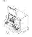
- the sample analyzer 1 of the embodiment of the present invention is configured by a measuring device 2, and a transporting apparatus 3 arranged on the front side of the measuring device 2 as shown in FIG. 1 .
- the measuring device 2 is housed within a housing 4 of the apparatus body.
- lid placing sections which accommodates lids 5a through 8a of a plurality of liquid containers 5 through 8 accommodating liquid such as reagent, washing solution and diluting liquid used in sample measurement operations in the measuring device 2, are provided inside and outside of the housing 4, as shown in FIGS. 1 and 2 .
- the sample analyzer 1 is provided with lid placing sections 16a through 16c disposed within the housing 4, and lid placing sections 32 through 34 disposed outside the housing 4.
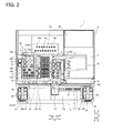
- the measuring device 2 has the functions of measuring a specimen prepared by mixing a sample and reagents, and analyzing the components of the sample. As shown in FIG. 2 , the measuring device 2 includes cuvette supplier 10, sample dispensing unit 11, sample plate setting unit 12, container setting units 13 through 15, lid placing sections 16a through 16c, reagent dispensing unit 17, cuvette moving unit 18, detecting unit 19, control unit 20, and display unit 21.
- the measuring device 2 is configured to obtain optical information related to a sample by performing optical measurements of a specimen prepared from a sample supplied from the transporting apparatus 3.
- a sample received from a sample container T on the transporting apparatus 3 and dispensed into a cuvette 9 as a reaction container is subjected to optical measurements by the measuring device 2.
- the cuvette supplier 10 is configured to accommodate a plurality of cuvettes 9, and supply the cuvettes 9 sequentially one at a time to a predetermined position.
- the sample dispensing unit 11 is provided with a pipette 11a as a suction tube for suctioning and discharging a sample, and is configured to be movable within a predetermined region which contains a sample suctioning position P1 and a sample dispensing position P2 via a moving mechanism that is not shown in the drawing.
- the sample dispensing unit 11 suctions the sample from the sample container T which was transported to the sample suctioning position P1 on the transport path 31 of the transporting apparatus 3.
- the sample dispensing unit 11 is configured to discharge the sample into a cuvette 9 disposed at the sample discharging position P2.
- the sample dispensing unit 11 is also configured to suction washing solution and diluting liquid from the washing solution container 5 set on the container setting unit 13 and the diluting liquid container 6 set on the container setting unit 14.
- the sample dispensing unit 11 functions as a sample suctioning unit to suction a sample from the sample container T, and a liquid suctioning unit to suction liquid from the washing solution container 5 and the diluting liquid container 6.
- Sample plates having a plurality of holes are aligned on the sample plate setting unit 12.
- the sample dispensing unit 11 is configured to collectively dispense a sample for each analysis item in the sample plate setting unit 12 when there are several analysis items for the same sample and a plurality of specimen corresponding to these analysis items must be prepared.
- the container setting units 13 and 14 are arranged centrally in the width direction of the sample analyzer 1, and the container setting unit 15 is arranged in an area on the left side (X2 direction side) facing the front (door 4a side) of the sample analyzer 1.
- Each type of liquid containers set in the container setting units 13 through 15 is set therein with the lid removed.
- the liquid accommodated within these liquid containers is suctioned by inserting the pipette 17a of the reagent dispensing unit 17 or the pipette 11a of the sample dispensing unit 11 through the opening at the top of the containers.
- lid placing sections 16a, 16b, 16c are disposed near the container setting units 13, 14, 15 to accommodate the lids of the liquid containers, that is, the lids of the washing solution container 5, diluting liquid container 6, and washing solution container 7, respectively.
- the lid placing sections 16a, 16b, 16c are placing areas formed on the inner bottom surface of the inside of the housing 4, and are configured to be adjacent to the liquid containers of the corresponding liquid containers, that is, the washing solution container 5, diluting liquid container 6, and washing solution container 7 set in the liquid container setting units 13, 14, 15.
- the washing solution containers 5, diluting liquid container 6, washing solution containers 7, and reagent containers 8 are generally referred to as "liquid containers.”
- the container setting unit 13 includes two large mounting apertures 13a for inserting the washing solution containers 5.
- the washing solution within the washing solution container 5 is used to wash the pipette 11 a of the sample dispensing unit 11.
- the mounting apertures 13a are provided aligned along the front-to-back direction (Y direction) of the sample analyzer 1.
- the lid placing section 16a is a square area for placing the lid 5a of the washing solution container 5, and two lid placing sections 16a are provided to correspond to the two mounting apertures 13a, so as to be adjacent to each mounting aperture 13a in the X1 direction.
- the lid placing section 16a is sized to match the size of the lid 5a, and has a concave shape to restrict the movement of the lid 5a in the horizontal direction.
- the container setting unit 14 includes three mounting apertures 14a for inserting diluting liquid containers 6.
- the three mounting apertures 14a are aligned along the Y direction at the front side (Y2 direction side) of the two mounting apertures 13a.
- the lid placing section 16b is a square area for placing the lid 6a of the diluting liquid containers 6, and three lid placing section 16b are provided to correspond to the three mounting apertures 14a, so as to be adjacent to each mounting aperture 14a in the X1 direction. Therefore, the container setting units 13 and 14, and the lid placing sections 16a and 16b are aligned in two rows in the Y direction.
- the lid placing section 16b is sized to match the size of the lid 6a, and has a concave shape to restrict the movement of the lid 6a in the horizontal direction.
- the container setting unit 15 is configured to accommodate a plurality of the large washing solution containers 7, and a plurality of reagent containers 8 which accommodate various kinds of reagent that are mixed to the sample when preparing the specimen for analysis from the sample.
- the container setting unit 15 is provided with two large mounting apertures 15a for two washing solution containers 7, and mounting apertures 15b, which are different from the two large mounting apertures 15a, for intermediate or small reagent containers 8.
- the washing solution within the washing solution container 7 is used to wash the pipette 17a of the reagent dispensing unit 17.
- the mounting apertures 15a are aligned in the Y direction at the X2 direction end of the container setting unit 15.
- the lid placing section 16c is a square area for placing lids 7a of the large washing solution containers 7, and there are two lid placing sections 16c aligned in the Y direction corresponding to the two mounting apertures 15a so as to be adjacent to the each mounting aperture 15a in the X2 direction.
- the lid placing section 16c is sized to match the size of the lid 7a, and has a concave shape to restrict the movement of the lid 7a in the horizontal direction.
- the lids 8a of the intermediate or small reagent containers 8 set in the mounting apertures 15b are placed in the lid placing sections 32 through 34 provided on the outside of the housing 4, as will be described later.
- the container setting units 13 through 15 have a cooling function of refrigerating and maintaining the liquids within the liquid containers 5 through 8 set in the container setting units 13 through 15 at a predetermined temperature via a refrigeration unit that is not shown in the drawing.
- the reagent dispensing unit 17 has a pipette 17a used as a suction tube for dispensing reagent, and is configured to be movable within a range which includes a reagent dispensing position P3 and above (Z1 direction) the container setting unit 15 via a moving mechanism which is not shown in the drawing.
- the reagent dispensing unit 17 is configured to suction reagent from a targeted reagent container 8 using the pipette 17a, and discharge the reagent to a cuvette 9 disposed at the reagent dispensing position P3.
- the reagent dispensing unit 17 also is configured to suction washing solution from the washing solution container 7 set in the container setting unit 15.
- the reagent dispensing unit 17 therefore functions as a liquid suctioning unit to suction liquid from the washing solution container 7 and the reagent container 8.
- the cuvette moving unit 18 has the functions of removing a cuvette 9 from the cuvette supplier 10, and moving the cuvette 9 to each of the various units, that is, the sample dispensing position P2, reagent dispensing position P3, and detecting unit 19 and the like.
- the cuvette moving unit 18 has a catcher 18a which holds the cuvette 9 and is movable.
- the cuvette moving unit 18 moves the catcher 18a by a moving mechanism not shown in the drawing, so that the sample and reagent in the cuvette 9 is mixed, or the cuvette 9 is removed or installed.
- the detecting unit 19 has the functions of heating the specimen for analysis prepared by mixing the reagent with the sample, and performing optical measurements of the sample.
- the detecting unit 19 has a plurality of cuvette holes 19a for inserting cuvettes 9.
- the specimen in the cuvette 9 held in the cuvette hole 19a is heated to a predetermined temperature by a heating mechanism not shown in the drawing to induce a reaction between the reagent and the sample.
- the detecting unit 19 is configured to irradiate the specimen in the cuvette 9 with measurement light guided from a light source 19b through an optical fiber or the like.
- the detecting unit 19 has a built-in photoreceptor element (not shown in the drawing) to receive the light irradiated on the specimen, and outputs detection signals corresponding to the amount of received light detected by the photoreceptor element.
- the obtained detection signal is output to the control unit 20.
- the control unit 20 is configured to analyze the amount and degree of activity of specific substances in the sample based on the obtained detection signals.
- the control unit 20 has the functions of displaying various screens containing analysis results on the display unit 21 which is arranged on the X1 direction side of the front of the housing 4 and perform operation controls of each part of the measuring device 2 and the transporting apparatus 3.
- the transporting apparatus 3 is configured to supply the sample to the measuring device 2 by transporting a rack R holding a plurality (maximum of 10 in the present embodiment) of the sample containers T containing samples to the sample suctioning position P1 of the measuring device 2.
- the transporting apparatus 3 includes a transport path 31 for transporting the rack R to the measuring device 2, and a plurality (3 in the present embodiment) of lid placing sections 32 through 34.
- the transport path 31 extends in the horizontal direction (X direction), and connects the rack supplier 31 a on the X1 direction side and the rack collector 31 b on the X2 direction side.
- the rack R holding the sample containers T is set in the rack supplier 31 a.
- the rack supplier 31 a has the function of sequentially supplying the set racks R to the transport path 31.
- the transport path 31 has the function of transporting the rack R received from the rack supplier 31 a to the sample suctioning position P1.
- the rack collector 31 b has the function of collecting from the transport path 31 the rack R holding the sample containers T from which the samples have been suctioned.
- the lid placing sections 32 through 34 are provided in the transporting apparatus 3 on the front side (Y2 direction side) from the container setting unit 13 on the outside of the housing 4.
- the lid placing sections 32 through 34 also are provided in different regions than the region in the transport path 31. Specifically, the lid placing sections 32 through 34 are aligned in the X direction with the transport path 31, and are disposed at positions on the outside positions in the X direction of the transport path 31 along the transport path 31 of the transporting apparatus 3, as shown in FIGS. 3 and 4 .
- the lid placing sections 32 through 34 are respectively positioned on bilateral sides so as to sandwich the transport path 31 therebetween at positions on the outside of the transport path 31 in the X direction, and positioned at both ends in the longitudinal direction of the transport path 31 as the X direction of the transporting apparatus 3.
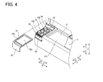
- the lid placing section 33 (refer to FIG. 4 ) has a cover 35 which covers the lid placing section 33, and the lid placing section 32 is provided on the top surface of the cover 35.
- the two lid placing sections which includes the lid placing section 32 disposed on the top surface of the cover 35 and the lid placing section 33 disposed inside the cover 35, are arranged on the X2 direction side, whereas the lid placing section 34 is singly arranged on the X1 direction side.
- the lid placing section 34 on the X1 direction side is arranged on the top surface of the light source cover 36 which covers the light source 19b (refer to FIG. 2 .
- the housing 4 of the sample analyzer 1 has a door 4a, which opens and closes the interior of the housing 4 to install and remove the liquid containers 5 through 8 in the container setting units 13 through 15, as shown in FIG. 1 .
- the door 4a is arranged on the X2 direction side, which is the same side as the container setting unit 15 in the planar view shown in FIG. 2 . Therefore, the lid placing sections 32 and 33 on the X2 direction side of the transporting apparatus 3 are arranged the front side (Y2 direction side) from the container setting unit 15 and on the same side (X2 direction side) as the door 4a and the container setting unit 15.
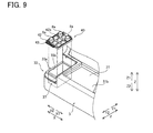
- Each of the lid placing sections 32 through 34 provided at three locations includes a tray 40 which has an area for placing a plurality of lids 8a, and tray placing sections 32a through 34a for removably installing the tray 40 (refer to FIGS. 3 and 9 ). Therefore, a total of three trays 40 can be simultaneously installed in the transporting apparatus 3.
- the trays 40 in the respective lid placing sections 32 through 34 are identical and mutually interchangeable.
- the trays 40 installed in the lid placing sections 32 through 34 are provided to place the lids 8a of the reagent containers 8 which have relatively small lids (that is, small to intermediate in size) among the lids of the plurality of liquid containers.
- the tray 40 is square in shape, and has a shallow bottom surface 41 (refer to FIG. 6 ) as the placing area of the lid 8a.
- the tray 40 therefore has a concave shape for placing the lid 8a on the bottom surface 41.
- the tray 40 is provided with a dividing member 42 used to divide the placing area on the bottom surface 41, a handle 43 for carrying the tray 40, and convex feet 44 facing downward from the under-surface of the bottom surface 41 (refer to FIG. 7 ).
- reagent can be caught and prevented from flowing out to the outside of the tray 40 even when reagent remaining on the lid 8a spills on the bottom surface 41 because the circumference of the bottom surface 41 is circumscribed by side walls. Therefore, malfunctions caused by spilling of the reagent on the transporting apparatus 3 is prevented. Note that the tray 40 can be washed when reagent adheres to the bottom surface 41.
- the dividing member 42 is connected to the top of the tray 40 so as to be openable and closable relative to the tray 40. Specifically, the dividing member 42 is connected to the tray 40 through a rotating shaft 42a along the short edge of the tray 40, and is openable and closable relative to the tray 40 when rotated in upward and downward direction by pivoting on the rotating shaft 42a.
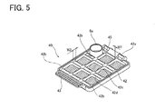
- the dividing member 42 is formed as a lattice so as to divide the placing area of the tray 40 into a plurality of areas. In the present embodiment, the dividing member 42 is formed in a lattice which divides the placing area into nine areas in a 3x3 pattern, such that a single tray 40 can classify and accommodate a total of none lids 8a in the divided area. Note that spilling the reagent adhered within the lid 8a is prevented because the lids 8a can be turned over in each divided area, as shown in FIG. 5 .
- the top surface of the dividing member 42 is provided with display areas 42b corresponding to each divided area and which show the types (names) of the reagents accommodated in the reagent containers 8 on which the lids 8a are to be installed. That is, the dividing member 42 is formed so that the width W2 of the lateral lattice part 42d is larger than the width W1 of the lattice part 42c in the longitudinal direction, and the top surface area of the wide width lattice part 42d becomes the display area 42b.
- the user manages the association between the divided areas and the lid 8a placed in the divided area by adhering a seal member printed with the name of the reagent in the reagent container 8 and directly entering the reagent name in the display area 42b.
- the dividing member 42 is configured to allow erasure of the entered text even when the reagent name is directly entered in pen. Therefore, the reagent name can be quickly applied by the user even, for example, when the user of the sample analyzer 1 changes to another person.
- the tray 40 is configured to hold an absorbing member 45 by opening the dividing member 42, arranging an absorbing member 45 on the bottom surface 41 between the tray 40 and the dividing member 42, then closing the dividing member 42, as shown in FIG. 6 .
- the absorbing member 45 is provided to absorb droplets of condensation and liquid reagent adhered to the lid 8a.
- the absorbing member 45 is not particularly limited insofar as it is an absorbent sheet, and a cleaning cloth such as waste paper, non-woven fabric, or felt may be used. Note that the hatch marks shown in FIG. 5 are provided to the absorbing member 45 for facilitating understanding.
- the handle 43 is formed to extend from the end of the tray 40.
- the handle 43 is formed with a wide profile extending substantially over the length of the short edge on one side of the square tray 40.
- the handle 43 functions as a user grip area when carrying the tray 40.
- the convex feet 44 are provided at four locations to form a square on the under-side surface of the tray 40, as shown in FIGS. 7 and 8 .
- Each foot 44 has a circular shape when viewed from the bottom surface side.
- the feet 44 are configured to engage the engaging parts 32b through 34b which are concave recess or hole of the tray placing units 32a through 34a when the tray 40 is installed on the tray placing units 32a through 34a provided on the three lid placing sections 32 through 34.
- the tray placing units 32a through 34a are provided to hold the tray 40 in the respective lid placing sections 32 through 34.
- the tray placing section 34a provided in the lid placing section 34 and the tray placing section 32a provided in the lid placing section 32 have identical shapes and are respectively provided on the cover 35 and on the light source cover 36.
- the tray placing section 33a provided in the lid placing section 33 is arranged at a predetermined position within the cover 35 (refer to FIG. 4 ).
- the tray placing sections 32a through 34a have engaging parts which are concave recesses or holes. Note that the cover 35 is configured to cover the lid placing section 33 including the tray 40 when the tray 40 is installed in the tray placing section 33a.
- the tray placing section 32a on the cover 35 and the tray placing section 34a on the light source cover 36 respectively have square concave engaging parts 32b (34b) on the top surface thereof, as shown in FIG. 3 .
- the tray placing section 33a on the inside of the cover 35 also has a square hole engaging part 33b.
- the feet 44 arranged in a square on the under-side surface of the tray 40 are inserted into the engaging parts 32b through 34b, such that the inner surface of the engaging parts 32b through 34b mutually engage the outer surface of the feet 44, as shown in FIG. 8 .
- the engagement between the trays 40 and the tray placing sections 32a through 34a can be released to remove the tray 40 by gripping the handle 43 of the tray 40 and lifting the tray 40 upward (Z1 direction).
- a square, open-top box-like storage compartment 37 is provided below the tray placing section 33a which is arranged inside of the cover 35.
- the storage compartment 37 is continuous with the hole-like engaging part 33b, and the engaging part 33b becomes the inlet aperture of the storage compartment 37.
- the storage compartment 37 is configured so that the inner part is closed by the tray 40 being installed in the tray placing section 33a (refer to FIG. 4 ).
- the storage compartment 37 may be used to store, for example, attachments and tools used during maintenance of the sample analyzer 1.
- the three lid placing sections 32 through 34 can accommodate a maximum of 27 large lids 8a when each of the trays 40 holds 9 lids 8a. Therefore, the lids 8a of all reagent containers 8 can be classified and placed in the lid placing sections 32 through 34 even when reagent containers 8 fill all 26 mounting apertures 15b of the container setting unit 15.
- the user When operating the sample analyzer 1, the user opens the door 4a of the housing 4 to set the respective liquid containers, that is, the washing solution container 5, diluting liquid container 6, washing solution container 7, and reagent containers 8 in the container setting units 13 through 15 (refer to FIG. 2 ), as shown in FIG. 1 .
- the lids 5a through 8a of each container are then removed.
- the lids 5a, 6a, and 7a are respectively placed in the lid placing sections 16a, 16b, and 16c which are adjacent to the mounting apertures 13a, 14a, and 15a in the X direction.
- the relational correspondence between container and lid therefore can be comprehended in a glance by storing the lids 5a, 6a, and 7a in this way.
- the lids 8a are placed in a predetermined divided area of the tray 40 in the lid placing sections 32 through 34.
- the lids 8a can be organized to prevent any mistakes in the relational correspondence between lid and container even when various types of reagent containers 8 are used because the user places the lid 8a according to the display in the display area 42b of the dividing member 42.
- the reagent adheres to the inside of the lid 8a, the reagent is prevented from adhering to another lid 8a of another reagent container 8 because an absorbing member 45 is arranged between the tray 40 and the dividing member 42.
- the refrigeration function of the container setting units 13 through 15 shuts off and the liquid containers, that is, the washing solution container 5, diluting liquid container 6, washing solution container 7, and reagent container 8 are stored in a refrigerator within the facility to prevent deterioration and evaporation of the liquids.
- the user therefore removes the liquid containers 5 through 8 from the container setting units 13 through 15, recaps the liquid containers with the corresponding lids 5a through 8a, and stores the capped liquid containers in the refrigerator.
- liquid containers 5 through 8 and the lids 5a through 8a are in an associated condition when the lids are placed at predetermined positions in the lid placing sections 16a through 16c and 32 through 34, the user installs the lid on the container and stores the container without losing the lid or returning the lid to the wrong liquid container.
- the user can place the lids 5a through 8a of the liquid containers 5 through 8 set in the container setting units 13 through 15 in the lid placing sections 16a through 16c by providing the lid placing sections 16a through 16c and 32 through 34 in which to place the lids 5a through 8a of the liquid containers, that is, the washing solution containers 5, diluting liquid containers 6, washing liquid containers 7, and reagent containers 8 as described above.
- the lids 5a through 8a of the liquid containers 5 through 8 can be stored without loss.
- the lid placing sections 16a through 16c and 32 through 34 By arranging the lid placing sections 16a through 16c and 32 through 34 near the container setting units 13 through 15 or on the front side of the container setting units 13 through 15, the user can observe the vicinity or front side of the container setting units 13 through 15 when installing the liquid containers 5 through 8 in the container setting units 13 through 15 and when removing the lids 5a through 8a, and the removed lids 5a through 8a can be placed in the lid placing sections 16a through 16c and 32 through 34 which are installed at easily accessible positions. as a result, forgetting where the lid was placed is avoided, and the work of the user is reduced thus improving the usability of the apparatus.
- the lid placing sections 32 through 34 are provided in the transporting apparatus 3 on the front side of the container setting units 15. In this way the user can place the lids 8a of the reagent containers 8 in the transporting apparatus 3 at the same location as the rack R holding the sample containers T is set, thus allowing easy placing and organization of the lids 8a and avoiding forgetting where the lids 8a are placed. Since the lid placing sections 32 through 34 are provided in the transporting apparatus 3 on the front side (Y2 direction side), they are more readily accessible to the user compared to placement within the housing 4 inside the measuring device 2, thus improving the ease of the lid placing operation and lid removing operation performed by the user.
- the lid placing sections 32 through 34 are aligned with the transport path 31 in a different region from the region in which the transport path 31 is provided. In this way placing the lids 5a through 8a can be easily organized when the rack R holding the sample containers T is installed in the transport path 31 or when the rack R holding the sample containers T is being transported.
- the lid placing sections 32 and 33, and the lid placing section 34 are provided on both sides of the transport path 31 in the X direction so that the transport path 31 is interposed therebetween. Therefore, a larger lid placing area for the lids 8a is ensured even when a large number of liquid containers (and thus a large number of lids) is used in the sample analyzer 1. Placement of the lids 8a is selective inasmuch as the most convenient lid placing area can be selected from among the lid placing sections 32 through 34 on bilateral sides.
- the tray 40 capable of accommodating a plurality of lids 8a, and tray placing section 32a through 34a are provided in the lid placing sections 32 through 34.
- the engaging parts 32b through 34b are provided on the top surface of the tray placing sections 32a through 34a, and feet 44 are provided to be fittedly engage the engaging parts 32b through 34b. Accordingly, the lid 8a on the tray 40 can be carried to a workbench when installing the lid 8a on the reagent container 8 since the lid 8 of the reagent container 8 can be moved for each tray. The situation of the user dropping the tray 40 is prevented by the engagement between the engaging parts 32b through 34b and the feet 44. In the present embodiment described above, the lids 8a are easily carried on the tray 40 because the tray 40 is provided with a handle 43.
- the storage compartment 37 is provided below the tray placing section 33a of the lid placing section 33.
- the storage compartment 37 is configured so that the inside area of the storage compartment 37 is closed by the tray 40 installed on the tray placing section 33a.
- the present embodiment described above prevents contamination by foreign matter being introduced into the reagent container 8 when the lid 8a is reseated on the reagent container 8 by providing the cover 35 to cover the lid placing section 33.
- the present embodiment described above ensures abundant locations to place the lids 8a by also providing the lid placing sections 32 on the top surface of the cover 35.
- the lid placing sections 32 through 34 are provided with a tray 40 and dividing member 42 which has sufficient area to accommodate a plurality of lids 8a. Since the lids 8a can be classified and organized when placed in the divided placement area, organization and management of the reagent containers 8 including the lids 8a can be easily accomplished.
- the lid placing sections 32 through 34 are provided outside the housing 4, and the lid placing sections 16a through 16c are provided inside the housing 4. Therefore, a larger lid placing area for the lids 5a through 8a is ensured even when a large number of liquid containers 5 through 8 is used in the sample analyzer 1.
- the lid placing sections 32 and 33 are arranged on the front side of the container setting unit 15 viewed from the front side (Y2 direction side) of the sample analyzer 1, that is, the same side as the door 4a and container setting unit 15 are on (X2 direction side). Therefore, the user can install and remove the reagent containers 8, store the lids 8a, and install the lid 8s on the removed reagent container 8 at the same position on the X2 direction side of the sample analyzer 1. As a result, the operation of setting the reagent container 8 and the operation of storing a reagent container 8 in a refrigerator within the facility are improved.
- the lid placing sections 16a through 16c are positioned near the container setting units 13 through 15 inside the housing 4, and the lid placing sections 32 through 34 are positioned on the front side of the container setting units 13 through 15 outside the housing 4, the present invention is not limited to this configuration.
- the lid placing sections also may be positioned only near the container setting units inside the housing, or the lid placing sections may be positioned only in front of the container setting units.
- the lid placing sections also may be arranged on the front side of the container setting units inside the housing.
- the lid placing sections are provided in a sample analyzer 1 which has a measuring device 2 and a transporting apparatus 3, the present invention is not limited to this configuration.
- the lid placing sections also may be provided in an independent transporting apparatus which can be connected to the sample analyzer that only has a measuring device.
- the lid placing sections are provided on the outer X direction side of the transport path alongside the transport path of the transporting apparatus
- the present invention is not limited to this configuration.
- the lid placing sections also may be provided at positions on the front side (Y2 direction side) of the transport path.
- the lid placing sections also may be configured so as to be pulled from the bottom of the transport path, the lids placed when the lid placing section is pulled from the front side (Y2 direction side), then returned to the bottom of the transport path.
- the lid placing sections are arranged on both side of the transport path in the X direction so as to sandwich the transport path therebetween, the present invention is not limited to this configuration.
- the lid placing sections also may be arranged on only the X1 direction side or the X2 direction side.
- lid placing sections 32 through 34 are described as having three lid placing sections 32 through 34 in the transporting apparatus, the present invention is not limited to this configuration. In the present invention, one, two or four or more lid placing sections also may be provided in the transporting apparatus.
- the present invention is not limited to this configuration.
- the tray may be omitted, and the lid placing section may be configured to accommodate the lid directly on the lid placing section.
- the present invention is not limited to this configuration.
- the tray may be simply placed on the tray placing section without engagement between the tray and the tray placing section.
- the tray itself may be configured to be fitted to the tray placing section without providing feet on the tray.
- the present invention is not limited to this configuration.
- the storage compartment may be omitted.
- an operating member (lid part) may be provided to open and close the entrance rather than closing the storage compartment via the tray.
- the present invention is not limited to this configuration and the handle may be omitted from the tray.
- the present invention is not limited to this configuration inasmuch as the cover 35 may be omitted.
- the lid placing section may be omitted on the top surface of the cover 35.
- the present invention is not limited to this configuration.
- the dividing member may be omitted from the tray.
- the placing region may be divided into more or fewer areas than the nine areas of the example.
- large lids 5a, 6a, and 7a may be placed on a tray divided into four areas in a 2x2 pattern.
- trays capable of accommodating large lids and tray capable of accommodating small lids may have different numbers of divided areas.
- the present invention is not limited to this example.
- the lid placing sections inside the housing also may be configured to accommodate small lids
- the lid placing sections outside the housing may be configured to accommodate large lids.
- the lid placing sections 16a through 16c inside the housing 4 are arranged adjacently and respectively associated with the washing solution container 5, diluting liquid container 6, and washing solution container 7, the present invention is not limited to this example.
- the lid placing sections also may be arranged a distance from the liquid containers. In this case, the lid placing sections may be provided together in a predetermined area separately from the position of the respective liquid container.
- the liquid container also may be containers containing liquids such as calibrator (calibration material) and control (standard sample) in addition to washing solution containers, diluting liquid container, and reagent containers insofar as the container holds a liquid used in the measuring device.
- calibrator calibration material
- control standard sample
Landscapes
- Chemical & Material Sciences (AREA)
- Biochemistry (AREA)
- Physics & Mathematics (AREA)
- Health & Medical Sciences (AREA)
- Life Sciences & Earth Sciences (AREA)
- Analytical Chemistry (AREA)
- General Health & Medical Sciences (AREA)
- General Physics & Mathematics (AREA)
- Immunology (AREA)
- Pathology (AREA)
- Chemical Kinetics & Catalysis (AREA)
- Automatic Analysis And Handling Materials Therefor (AREA)
- Sampling And Sample Adjustment (AREA)
Abstract
Description
- The present invention relates to a sample analyzer, and specifically relates to a sample analyzer with a container setting unit for setting a plurality of liquid containers.
- There are known conventional sample analyzers having a container setting unit for setting a plurality of liquid containers (for example, refer to
US Patent Application publication No. 2009/004057 ). -
US Patent Application publication No. 2009/004057 discloses a sample analyzer configured to measure a specimen prepared by mixing a sample and reagent, and which is provided with a container setting unit for accommodating in a refrigerated state a plurality of reagent containers which contain reagents to be used in measurements. The reagent container setting unit is configured to receive each type of reagent container with the lid opened in an internal empty space which is closed off by a cover and case section. The reagent in the reagent container is aspirated by a reagent dispensing probe and discharged therefrom for mixing with a sample. - In the conventional sample analyzer disclosed
US Patent Application publication No. 2009/004057 , when the analyzer is no longer in use following the completion of measurements, the reagent containers are removed from the reagent container setting unit, the reagent containers then are capped to prevent evaporation and deterioration of the reagent, and the reagent containers are stored in a refrigerator within the facility. In this case, the user recaps the reagent containers removed for current use after measurement operations have been completed each day. However, once a lid has been removed from a reagent container, the user may have forgotten where the removed lid was placed when stowing away the container, or the user simply may lose the lid. Note that in the case of this sample analyzer, liquids such as cleaning solution and dilutant, calibrators used for accuracy control, and controls (standard specimens) also are used and may require handling similar to the reagent containers. Therefore, it is imperative to not lose the lids of the various liquid containers, including those of the reagent containers. - To eliminate these problems, an object of the present invention is to provide a sample analyzer which makes it possible to keep track of the lids of the liquid containers which are used in the sample analyzer, and a transporting apparatus and lid placing tray to be used with this sample analyzer.
- The scope of the present invention is defined solely by the appended claims, and is not affected to any degree by the statements within this summary.
- (1) A first aspect of the present invention is a sample analyzer, comprising:
- a container setting unit for setting a plurality of liquid containers accommodating liquids;
- a detecting unit configured to perform a measurement operation for a sample using the liquid;
- a liquid suctioning unit including a suction tube for suctioning the liquid from at least one of the plurality of liquid containers; and
- a lid placing section for placing a lid of at least one of the plurality of the liquid containers.
- According to this configuration, the user can use the lid placing section to store the lid of a liquid container held in the container setting unit so as to not lose the lid of the liquid container.
- (2) The sample analyzer according to (1), further comprising:
- a transporting apparatus configured to transport sample containers containing samples; and
- a sample suctioning unit configured to suction a sample accommodated in a sample container transported by the transporting apparatus;
- wherein the lid placing section is provided in the transporting apparatus.
- According to this configuration, lid placement and management can be easily accomplished and forgetting where the lid was placed can be avoided because the user places the lid of the liquid container by the transporting apparatus at the same location at which the liquid container is set.
- (3) The sample analyzer according to (2), wherein
- the transporting apparatus comprises a transport path configured to transport the sample containers;
- the lid placing section is arranged in a different region from a region in which the transport path is provided.
- According to this configuration, placing and arranging the lids can be easily accomplished even when the sample container is placed in the transport path or during the transport of the sample container.
- (4) The sample analyzer according to (3), wherein
- the lid placing section is disposed at either bilateral end in the longitudinal direction of the transport path.
- According to this configuration, the lid of the liquid container can be placed at a position on either side of the transport path. Therefore, a larger lid placing area is ensured even when a large number of liquid containers, and thus a large number of lids, is used in the sample analyzer. Lid placement is selective inasmuch as the most convenient lid placing area can be selected from the lid placing section on bilateral sides.
- (5) The sample analyzer according to any one of (1) to (4), wherein
- the lid placing section is arranged near or on the front side from the container setting unit.
- According to this configuration, when the user sets a liquid container in the container setting unit and removes the lid, the user can place the lid in the lid placing section arranged near or on the front side of the liquid container setting unit at an easily visually verifiable and easily accessible position. Hence, forgetting where the lid was placed is avoided, and the work of the user is reduced to improve the usability of the apparatus.
- (6) The sample analyzer according to any one of (1) to (5), wherein the lid placing section has a concave shape to accommodate the lid.
- According to this configuration, hindering measurement occurred by horizontal movement of the lid placed in the lid placing section is avoided.
- (7) The sample analyzer according to any one of (1) to (6), wherein
- the lid placing section is divided into a plurality of areas according to the plurality of liquid containers set on the container setting unit so as to accommodate lids one by one in each area.
- According to this configuration, the liquid container and its lid have a clear relational correspondence allowing for easy regulation of the lid.
- (8) The sample analyzer according to (7), wherein
- the lid placing section is divided into a plurality of areas for each size of the lids.
- According to this configuration, the relational correspondence between the liquid container and the lid is clarified, and space is efficiently used within the apparatus.
- (9) The sample analyzer according to any one of (1) to (8), wherein
- the lid placing section comprises a tray with an area for placing a plurality of lids, and a tray placing section for removably installing the tray;
- wherein the tray placing section has a concave or hole first engaging part on the top surface thereof, and
- the tray has a convex second engaging part which fittedly engages the first engaging part when the tray is installed in the tray placing section.
- According to this configuration, the lid placed on the tray can be carried to a workbench when installing the lid on the liquid container since the lid of the liquid container can be moved for each tray. The first engaging part and the second engaging part can be linked simply by providing a tray on the tray placing section. The user error of dropping the tray is thus avoided by the structure of placing the lid on the removable tray.
- (10) The sample analyzer according to any one of (1) to (9), wherein
- the lid placing section comprises a tray with an area for placing a plurality of lids, and a tray placing section for removably installing the tray;
- the sample analyzer further comprises a storage compartment which is open at the top and is provided below the tray placing section;
- the storage compartment is configured so that the inner area is closed when the tray is installed in the tray placing section.
- According to this configuration, a storage compartment also can be provided in the sample analyzer using the area in which the lid placing section is accommodated. The convenience of the sample analyzer is improved for the user who is no longer concerned about missing components inasmuch as attachments other than the lids of the liquid containers can also be stored in the storage compartment.
- (11) The sample analyzer according to (9) or (10), wherein
the tray has a handle for carrying the tray. - According to this configuration, it is easy to carry the lids on the tray by gripping the handle of the tray when the user carries the tray.
- (12) The sample analyzer according to any one of (1) to (11), further comprising:
- a cover configured to cover the lid placing section.
- According to this configuration, contamination of the liquid container by foreign matter can be prevented when recapping the lid on the liquid container because the cover which covers the lid placing section prevents dust and sample from adhering to the lid of the liquid container.
- (13) The sample analyzer according to (12), further comprising:
- an another lid placing section for placing a lid of at least one of the plurality of the liquid containers, wherein
- the another lid placing section is provided on the top surface of the cover.
- According to this configuration, many more lid placing locations are ensured by placing the lids on the lid placing section on the top of the cover that covers the lid placing section.
- (14) The sample analyzer according to any one of (1) to (13), wherein
- the lid placing section comprises a tray with an area for placing a plurality of lids, and a dividing member provided on the tray to divide the area.
- According to this configuration, management and regulation of the liquid containers including the lids is easily accomplished by classifying and arranging the lids in the divided placing areas even when placing the lids of a plurality of different types of liquid containers on the tray.
- (15) The sample analyzer according to (14), wherein
- the container setting unit is configured to accommodate a plurality of reagent containers that contain a plurality of types of reagents to be mixed with samples;
- a display area is provided on the dividing member to show the type of reagent accommodated in the reagent container fitted with a lid.
- According to this configuration, Each placing region divided by the dividing members correspond to the types of reagent corresponding to the lids placed in each placing region. Management and adjustment of the reagent containers used in the sample analyzer is therefore easily accomplished and error in mistakenly recapping a reagent container with the lid of another reagent container is prevented.
- (16) The sample analyzer according to (14) or (15), wherein
the dividing member is connected to the top of the tray so as to be openable and closable;
the lid placing section is configured to retain an absorbing member by closing the dividing member when the absorbing member is arranged between the tray and the dividing member. - According to this configuration, when the lid is placed on the tray, the liquid reagent in the liquid container and the droplets of condensation may be absorbed or adhere to the lid via an absorbing member, thus preventing the liquid on the tray from adhering to the lid of another liquid container or adhering to the user.
- (17) The sample analyzer according to any one of (1) to (16), further comprising:
- a housing configured to accommodate the liquid suctioning unit and the container setting unit inside, wherein
- the lid placing section comprises a first lid placing section provided on the front side from the container setting unit on the outside of the housing, and a second lid placing section provided near the container setting unit within the housing.
- According to this configuration, more lid placing locations are ensured even when a large number of liquid containers, that is, a large number of lids, are used in the sample analyzer because a first lid placing section is provided outside the housing and a second lid placing section is provided inside the housing.
- (18) The sample analyzer according to (17), wherein
the first lid placing section is configured to accommodate relatively small lids among the lids of the plurality of liquid containers;
the second lid placing section is configured to accommodate relatively large lids among the lids of the plurality of liquid containers. - According to this configuration, large size lids are easily stored in the second placing section within the housing because there is no concern that it will be lost among other containers placed within the housing. The user can place small size lids in batches in the first lid placing section outside the housing and kept easily organized outside the housing, since there is a tendency of having larger numbers of containers and types of each kind of reagent.
- (19) The sample analyzer according to (18), wherein
- the container setting unit is configured to accommodate reagent containers accommodating reagents to be mixed with a sample, and washing solution containers accommodating washing solution used to clean the suction tube;
- the first lid placing section is configured to accommodate lids of the reagent containers;
- the second lid placing section is configured to accommodate lids of the washing solution containers.
- According to this configuration, management and organization of the lids is easily accomplished and users avoid mistakenly recapping a reagent container lid on a washing solution container or mistakenly recapping a washing solution container lid on a reagent container because the reagent container lids and the washing solution container lids are kept separate.
- (20) The sample analyzer according to any one of (1) to (19), wherein
the lid placing section is provided at a position corresponding to a position of the plurality of liquid containers set on the container setting unit. - According to this configuration, management of the liquid containers and their lids is easily accomplished even when lids are placed within the housing because lids of liquid containers set in the container setting unit are placed in a position corresponding to the liquid containers.
- (21) The sample analyzer according to any one of (1) to (20), further comprising:
- a housing configured to accommodate the liquid suctioning unit and the container setting unit inside, wherein
- the housing is arranged on the same side as the installed container setting unit viewed from the front side of the sample analyzer, and has a door which opens and closes the inner area of the housing to remove and insert the liquid containers of the container setting unit;
- the lid placing section is arranged on the front side from the container setting unit, and the door and the container setting unit are on the same side viewed from the front side of the sample analyzer.
- According to this configuration, the user removes and inserts a liquid container in the container setting unit by opening a door, and stores the lid of the liquid container in the lid placing section and recaps the removed liquid container all while remaining in the same position. Therefore, the operation of setting the liquid container and the operation of storing a liquid container in a refrigerator within the facility are improved.
- (22) A transporting apparatus, comprising:
- a transport path configured to move a sample container accommodating a sample to the measuring device which performs a measurement operation on a sample using at least one of a plurality of liquids;
- a lid placing section for placing a lid of at least one of a plurality of liquid containers accommodating the plurality of liquids.
- According to this configuration, the user can use the lid placing section to store the lid of a liquid container held in the container setting unit so as to not lose the lid of the liquid container. The user can place the lid in the lid placing section at an easily verified and readily accessible position by providing the lid placing section in the transporting apparatus which performs the operation of installing the sample containers prior to sample analysis. Therefore, work load of the user is reduced and convenience of the sample analyzer is improved because the user will not forget where the lid was placed on the lid placing section, and organization (installing) of the lid of the liquid container and the operation of installing the liquid container are consolidated in the same transporting apparatus.
- (23) A lid placing tray which is removably installed in the sample analyzer for measuring a sample using a liquid, the sample analyzer provided with a container setting unit for setting a plurality of liquid containers accommodating liquids to be used in the measurement of the sample, and a liquid suctioning unit for suctioning a liquid by inserting a suction tube in a liquid container set on the container setting unit, the lid placing tray comprising:
- a placing area which accommodates lids of a plurality of containers; and
- a dividing member configured to divide the placing area into a plurality of areas corresponding to the plurality of liquid containers.
- According to this configuration, the user will not lose the lid of a liquid container used in the sample analyzer when the lid is placed in a removable lid placing tray installed in the sample analyzer. Management and organization of the lids of the liquid containers are easily accomplished by classifying and arranging the lids in the divided placing areas even when placing the lids of a plurality of different types of liquid containers on the tray.
-
-
FIG. 1 is a perspective view showing the structure of the sample analyzer of an embodiment of the present invention; -
FIG. 2 is a brief schematic plan view showing the structure of the sample analyzer of an embodiment of the present invention; -
FIG. 3 is an enlarged perspective view showing the lid placing section of the transporting apparatus; -
FIG. 4 is an enlarged perspective view showing the cover removed from the lid placing section of the transporting apparatus; -
FIG. 5 is a perspective view showing the tray provided in the lid placing section of the transporting apparatus; -
FIG. 6 is a perspective view showing the opened dividing member of the tray shown inFIG. 5 ; -
FIG. 7 is bottom view of the tray shown inFIG. 5 ; -
FIG. 8 is a schematic partial sectional view showing the tray fromFIG. 5 installed in the tray placing section; and -
FIG. 9 is an enlarged perspective view showing the storage compartment provided in the transporting apparatus. - The preferred embodiments of the present invention will be described hereinafter with reference to the drawings.
- The embodiments of the present invention are described below based on the drawings.
- The general structure of the sample analyzer 1 of an embodiment of the present invention is described below with reference to
FIGS. 1 through 9 . - The sample analyzer 1 of the embodiment of the present invention is configured by a measuring
device 2, and a transportingapparatus 3 arranged on the front side of the measuringdevice 2 as shown inFIG. 1 . The measuringdevice 2 is housed within a housing 4 of the apparatus body. In the present embodiment, lid placing sections, which accommodateslids 5a through 8a of a plurality of liquid containers 5 through 8 accommodating liquid such as reagent, washing solution and diluting liquid used in sample measurement operations in themeasuring device 2, are provided inside and outside of the housing 4, as shown inFIGS. 1 and2 . Specifically, the sample analyzer 1 is provided withlid placing sections 16a through 16c disposed within the housing 4, andlid placing sections 32 through 34 disposed outside the housing 4. - The measuring
device 2 has the functions of measuring a specimen prepared by mixing a sample and reagents, and analyzing the components of the sample. As shown inFIG. 2 , the measuringdevice 2 includescuvette supplier 10,sample dispensing unit 11, sampleplate setting unit 12,container setting units 13 through 15,lid placing sections 16a through 16c,reagent dispensing unit 17,cuvette moving unit 18, detectingunit 19, control unit 20, anddisplay unit 21. - The measuring
device 2 is configured to obtain optical information related to a sample by performing optical measurements of a specimen prepared from a sample supplied from the transportingapparatus 3. In the sample analyzer 1 of the present embodiment, a sample received from a sample container T on the transportingapparatus 3 and dispensed into acuvette 9 as a reaction container is subjected to optical measurements by the measuringdevice 2. - The
cuvette supplier 10 is configured to accommodate a plurality ofcuvettes 9, and supply thecuvettes 9 sequentially one at a time to a predetermined position. - The
sample dispensing unit 11 is provided with apipette 11a as a suction tube for suctioning and discharging a sample, and is configured to be movable within a predetermined region which contains a sample suctioning position P1 and a sample dispensing position P2 via a moving mechanism that is not shown in the drawing. Thesample dispensing unit 11 suctions the sample from the sample container T which was transported to the sample suctioning position P1 on thetransport path 31 of the transportingapparatus 3. Thesample dispensing unit 11 is configured to discharge the sample into acuvette 9 disposed at the sample discharging position P2. Thesample dispensing unit 11 is also configured to suction washing solution and diluting liquid from the washing solution container 5 set on thecontainer setting unit 13 and the dilutingliquid container 6 set on thecontainer setting unit 14. Thus, thesample dispensing unit 11 functions as a sample suctioning unit to suction a sample from the sample container T, and a liquid suctioning unit to suction liquid from the washing solution container 5 and the dilutingliquid container 6. - Sample plates having a plurality of holes are aligned on the sample
plate setting unit 12. Thesample dispensing unit 11 is configured to collectively dispense a sample for each analysis item in the sampleplate setting unit 12 when there are several analysis items for the same sample and a plurality of specimen corresponding to these analysis items must be prepared. - The
container setting units container setting unit 15 is arranged in an area on the left side (X2 direction side) facing the front (door 4a side) of the sample analyzer 1. Each type of liquid containers set in thecontainer setting units 13 through 15 is set therein with the lid removed. The liquid accommodated within these liquid containers is suctioned by inserting thepipette 17a of thereagent dispensing unit 17 or thepipette 11a of thesample dispensing unit 11 through the opening at the top of the containers. In the present embodiment,lid placing sections container setting units liquid container 6, andwashing solution container 7, respectively. Thelid placing sections liquid container 6, andwashing solution container 7 set in the liquidcontainer setting units liquid container 6,washing solution containers 7, andreagent containers 8 are generally referred to as "liquid containers." - The
container setting unit 13 includes twolarge mounting apertures 13a for inserting the washing solution containers 5. The washing solution within the washing solution container 5 is used to wash thepipette 11 a of thesample dispensing unit 11. The mountingapertures 13a are provided aligned along the front-to-back direction (Y direction) of the sample analyzer 1. Thelid placing section 16a is a square area for placing thelid 5a of the washing solution container 5, and twolid placing sections 16a are provided to correspond to the two mountingapertures 13a, so as to be adjacent to each mountingaperture 13a in the X1 direction. Thelid placing section 16a is sized to match the size of thelid 5a, and has a concave shape to restrict the movement of thelid 5a in the horizontal direction. - The
container setting unit 14 includes three mountingapertures 14a for inserting dilutingliquid containers 6. The three mountingapertures 14a are aligned along the Y direction at the front side (Y2 direction side) of the two mountingapertures 13a. Thelid placing section 16b is a square area for placing thelid 6a of the dilutingliquid containers 6, and threelid placing section 16b are provided to correspond to the three mountingapertures 14a, so as to be adjacent to each mountingaperture 14a in the X1 direction. Therefore, thecontainer setting units lid placing sections lid placing section 16b is sized to match the size of thelid 6a, and has a concave shape to restrict the movement of thelid 6a in the horizontal direction. - The
container setting unit 15 is configured to accommodate a plurality of the largewashing solution containers 7, and a plurality ofreagent containers 8 which accommodate various kinds of reagent that are mixed to the sample when preparing the specimen for analysis from the sample. Specifically, thecontainer setting unit 15 is provided with twolarge mounting apertures 15a for twowashing solution containers 7, and mountingapertures 15b, which are different from the twolarge mounting apertures 15a, for intermediate orsmall reagent containers 8. The washing solution within thewashing solution container 7 is used to wash thepipette 17a of thereagent dispensing unit 17. There are a total of 26 mountingapertures 15b for setting various types ofreagent containers 8. The mountingapertures 15a are aligned in the Y direction at the X2 direction end of thecontainer setting unit 15. Thelid placing section 16c is a square area for placinglids 7a of the largewashing solution containers 7, and there are twolid placing sections 16c aligned in the Y direction corresponding to the two mountingapertures 15a so as to be adjacent to the each mountingaperture 15a in the X2 direction. Thelid placing section 16c is sized to match the size of thelid 7a, and has a concave shape to restrict the movement of thelid 7a in the horizontal direction. Thelids 8a of the intermediate orsmall reagent containers 8 set in the mountingapertures 15b are placed in thelid placing sections 32 through 34 provided on the outside of the housing 4, as will be described later. - The
container setting units 13 through 15 have a cooling function of refrigerating and maintaining the liquids within the liquid containers 5 through 8 set in thecontainer setting units 13 through 15 at a predetermined temperature via a refrigeration unit that is not shown in the drawing. - The
reagent dispensing unit 17 has apipette 17a used as a suction tube for dispensing reagent, and is configured to be movable within a range which includes a reagent dispensing position P3 and above (Z1 direction) thecontainer setting unit 15 via a moving mechanism which is not shown in the drawing. Thereagent dispensing unit 17 is configured to suction reagent from a targetedreagent container 8 using thepipette 17a, and discharge the reagent to acuvette 9 disposed at the reagent dispensing position P3. Thereagent dispensing unit 17 also is configured to suction washing solution from thewashing solution container 7 set in thecontainer setting unit 15. Thereagent dispensing unit 17 therefore functions as a liquid suctioning unit to suction liquid from thewashing solution container 7 and thereagent container 8. - The
cuvette moving unit 18 has the functions of removing acuvette 9 from thecuvette supplier 10, and moving thecuvette 9 to each of the various units, that is, the sample dispensing position P2, reagent dispensing position P3, and detectingunit 19 and the like. Thecuvette moving unit 18 has acatcher 18a which holds thecuvette 9 and is movable. Thecuvette moving unit 18 moves thecatcher 18a by a moving mechanism not shown in the drawing, so that the sample and reagent in thecuvette 9 is mixed, or thecuvette 9 is removed or installed. - The detecting
unit 19 has the functions of heating the specimen for analysis prepared by mixing the reagent with the sample, and performing optical measurements of the sample. The detectingunit 19 has a plurality ofcuvette holes 19a for insertingcuvettes 9. The specimen in thecuvette 9 held in thecuvette hole 19a is heated to a predetermined temperature by a heating mechanism not shown in the drawing to induce a reaction between the reagent and the sample. The detectingunit 19 is configured to irradiate the specimen in thecuvette 9 with measurement light guided from alight source 19b through an optical fiber or the like. The detectingunit 19 has a built-in photoreceptor element (not shown in the drawing) to receive the light irradiated on the specimen, and outputs detection signals corresponding to the amount of received light detected by the photoreceptor element. - The obtained detection signal is output to the control unit 20. The control unit 20 is configured to analyze the amount and degree of activity of specific substances in the sample based on the obtained detection signals. The control unit 20 has the functions of displaying various screens containing analysis results on the
display unit 21 which is arranged on the X1 direction side of the front of the housing 4 and perform operation controls of each part of the measuringdevice 2 and the transportingapparatus 3. - The transporting
apparatus 3 is configured to supply the sample to themeasuring device 2 by transporting a rack R holding a plurality (maximum of 10 in the present embodiment) of the sample containers T containing samples to the sample suctioning position P1 of the measuringdevice 2. The transportingapparatus 3 includes atransport path 31 for transporting the rack R to themeasuring device 2, and a plurality (3 in the present embodiment) oflid placing sections 32 through 34. - The
transport path 31 extends in the horizontal direction (X direction), and connects therack supplier 31 a on the X1 direction side and therack collector 31 b on the X2 direction side. The rack R holding the sample containers T is set in therack supplier 31 a. Therack supplier 31 a has the function of sequentially supplying the set racks R to thetransport path 31. Thetransport path 31 has the function of transporting the rack R received from therack supplier 31 a to the sample suctioning position P1. Therack collector 31 b has the function of collecting from thetransport path 31 the rack R holding the sample containers T from which the samples have been suctioned. - As shown in
FIGS. 1 and2 , thelid placing sections 32 through 34 are provided in the transportingapparatus 3 on the front side (Y2 direction side) from thecontainer setting unit 13 on the outside of the housing 4. Thelid placing sections 32 through 34 also are provided in different regions than the region in thetransport path 31. Specifically, thelid placing sections 32 through 34 are aligned in the X direction with thetransport path 31, and are disposed at positions on the outside positions in the X direction of thetransport path 31 along thetransport path 31 of the transportingapparatus 3, as shown inFIGS. 3 and4 . Thelid placing sections 32 through 34 are respectively positioned on bilateral sides so as to sandwich thetransport path 31 therebetween at positions on the outside of thetransport path 31 in the X direction, and positioned at both ends in the longitudinal direction of thetransport path 31 as the X direction of the transportingapparatus 3. The lid placing section 33 (refer toFIG. 4 ) has acover 35 which covers thelid placing section 33, and thelid placing section 32 is provided on the top surface of thecover 35. In the present embodiment, therefore, the two lid placing sections, which includes thelid placing section 32 disposed on the top surface of thecover 35 and thelid placing section 33 disposed inside thecover 35, are arranged on the X2 direction side, whereas thelid placing section 34 is singly arranged on the X1 direction side. Note that thelid placing section 34 on the X1 direction side is arranged on the top surface of the light source cover 36 which covers thelight source 19b (refer toFIG. 2 . - Note that the housing 4 of the sample analyzer 1 has a
door 4a, which opens and closes the interior of the housing 4 to install and remove the liquid containers 5 through 8 in thecontainer setting units 13 through 15, as shown inFIG. 1 . Thedoor 4a is arranged on the X2 direction side, which is the same side as thecontainer setting unit 15 in the planar view shown inFIG. 2 . Therefore, thelid placing sections apparatus 3 are arranged the front side (Y2 direction side) from thecontainer setting unit 15 and on the same side (X2 direction side) as thedoor 4a and thecontainer setting unit 15. - Each of the
lid placing sections 32 through 34 provided at three locations includes atray 40 which has an area for placing a plurality oflids 8a, andtray placing sections 32a through 34a for removably installing the tray 40 (refer toFIGS. 3 and9 ). Therefore, a total of threetrays 40 can be simultaneously installed in the transportingapparatus 3. Thetrays 40 in the respectivelid placing sections 32 through 34 are identical and mutually interchangeable. Thetrays 40 installed in thelid placing sections 32 through 34 are provided to place thelids 8a of thereagent containers 8 which have relatively small lids (that is, small to intermediate in size) among the lids of the plurality of liquid containers. - As shown in
FIGS. 5 and6 , thetray 40 is square in shape, and has a shallow bottom surface 41 (refer toFIG. 6 ) as the placing area of thelid 8a. Thetray 40 therefore has a concave shape for placing thelid 8a on thebottom surface 41. Thetray 40 is provided with a dividingmember 42 used to divide the placing area on thebottom surface 41, ahandle 43 for carrying thetray 40, andconvex feet 44 facing downward from the under-surface of the bottom surface 41 (refer toFIG. 7 ). - As shown in
FIG. 6 , reagent can be caught and prevented from flowing out to the outside of thetray 40 even when reagent remaining on thelid 8a spills on thebottom surface 41 because the circumference of thebottom surface 41 is circumscribed by side walls. Therefore, malfunctions caused by spilling of the reagent on the transportingapparatus 3 is prevented. Note that thetray 40 can be washed when reagent adheres to thebottom surface 41. - The dividing
member 42 is connected to the top of thetray 40 so as to be openable and closable relative to thetray 40. Specifically, the dividingmember 42 is connected to thetray 40 through arotating shaft 42a along the short edge of thetray 40, and is openable and closable relative to thetray 40 when rotated in upward and downward direction by pivoting on therotating shaft 42a. The dividingmember 42 is formed as a lattice so as to divide the placing area of thetray 40 into a plurality of areas. In the present embodiment, the dividingmember 42 is formed in a lattice which divides the placing area into nine areas in a 3x3 pattern, such that asingle tray 40 can classify and accommodate a total ofnone lids 8a in the divided area. Note that spilling the reagent adhered within thelid 8a is prevented because thelids 8a can be turned over in each divided area, as shown inFIG. 5 . - As shown in
FIG. 5 , the top surface of the dividingmember 42 is provided withdisplay areas 42b corresponding to each divided area and which show the types (names) of the reagents accommodated in thereagent containers 8 on which thelids 8a are to be installed. That is, the dividingmember 42 is formed so that the width W2 of thelateral lattice part 42d is larger than the width W1 of thelattice part 42c in the longitudinal direction, and the top surface area of the widewidth lattice part 42d becomes thedisplay area 42b. The user manages the association between the divided areas and thelid 8a placed in the divided area by adhering a seal member printed with the name of the reagent in thereagent container 8 and directly entering the reagent name in thedisplay area 42b. Note that the dividingmember 42 is configured to allow erasure of the entered text even when the reagent name is directly entered in pen. Therefore, the reagent name can be quickly applied by the user even, for example, when the user of the sample analyzer 1 changes to another person. - The
tray 40 is configured to hold an absorbingmember 45 by opening the dividingmember 42, arranging an absorbingmember 45 on thebottom surface 41 between thetray 40 and the dividingmember 42, then closing the dividingmember 42, as shown inFIG. 6 . The absorbingmember 45 is provided to absorb droplets of condensation and liquid reagent adhered to thelid 8a. The absorbingmember 45 is not particularly limited insofar as it is an absorbent sheet, and a cleaning cloth such as waste paper, non-woven fabric, or felt may be used. Note that the hatch marks shown inFIG. 5 are provided to the absorbingmember 45 for facilitating understanding. - The
handle 43 is formed to extend from the end of thetray 40. Thehandle 43 is formed with a wide profile extending substantially over the length of the short edge on one side of thesquare tray 40. Thehandle 43 functions as a user grip area when carrying thetray 40. - The
convex feet 44 are provided at four locations to form a square on the under-side surface of thetray 40, as shown inFIGS. 7 and8 . Eachfoot 44 has a circular shape when viewed from the bottom surface side. As will be described later, thefeet 44 are configured to engage the engagingparts 32b through 34b which are concave recess or hole of thetray placing units 32a through 34a when thetray 40 is installed on thetray placing units 32a through 34a provided on the threelid placing sections 32 through 34. - As shown in
FIGS. 3 ,4 , and9 , thetray placing units 32a through 34a are provided to hold thetray 40 in the respectivelid placing sections 32 through 34. As shown inFIG. 3 , thetray placing section 34a provided in thelid placing section 34 and thetray placing section 32a provided in thelid placing section 32 have identical shapes and are respectively provided on thecover 35 and on thelight source cover 36. As shown inFIG. 9 , thetray placing section 33a provided in thelid placing section 33 is arranged at a predetermined position within the cover 35 (refer toFIG. 4 ). Thetray placing sections 32a through 34a have engaging parts which are concave recesses or holes. Note that thecover 35 is configured to cover thelid placing section 33 including thetray 40 when thetray 40 is installed in thetray placing section 33a. - Specifically, the
tray placing section 32a on thecover 35 and thetray placing section 34a on the light source cover 36 respectively have square concaveengaging parts 32b (34b) on the top surface thereof, as shown inFIG. 3 . As shown inFIG. 9 , thetray placing section 33a on the inside of thecover 35 also has a squarehole engaging part 33b. Thefeet 44 arranged in a square on the under-side surface of thetray 40 are inserted into the engagingparts 32b through 34b, such that the inner surface of the engagingparts 32b through 34b mutually engage the outer surface of thefeet 44, as shown inFIG. 8 . The engagement between thetrays 40 and thetray placing sections 32a through 34a can be released to remove thetray 40 by gripping thehandle 43 of thetray 40 and lifting thetray 40 upward (Z1 direction). - As shown in
FIG. 9 , a square, open-top box-like storage compartment 37 is provided below thetray placing section 33a which is arranged inside of thecover 35. Thestorage compartment 37 is continuous with the hole-likeengaging part 33b, and theengaging part 33b becomes the inlet aperture of thestorage compartment 37. Thestorage compartment 37 is configured so that the inner part is closed by thetray 40 being installed in thetray placing section 33a (refer toFIG. 4 ). Thestorage compartment 37 may be used to store, for example, attachments and tools used during maintenance of the sample analyzer 1. - The three
lid placing sections 32 through 34 can accommodate a maximum of 27large lids 8a when each of thetrays 40holds 9lids 8a. Therefore, thelids 8a of allreagent containers 8 can be classified and placed in thelid placing sections 32 through 34 even whenreagent containers 8 fill all 26 mountingapertures 15b of thecontainer setting unit 15. - The effect of the sample analyzer 1 of the present embodiment is described below.
- When operating the sample analyzer 1, the user opens the
door 4a of the housing 4 to set the respective liquid containers, that is, the washing solution container 5, dilutingliquid container 6,washing solution container 7, andreagent containers 8 in thecontainer setting units 13 through 15 (refer toFIG. 2 ), as shown inFIG. 1 . Thelids 5a through 8a of each container are then removed. As shown inFIG. 2 , when the large washing solution container 5, dilutingliquid container 6, andwashing solution container 7 are set in the mountingapertures lids lid placing sections apertures lids - When the small and
intermediate reagent containers 8 are set in the mountingapertures 15b, thelids 8a are placed in a predetermined divided area of thetray 40 in thelid placing sections 32 through 34. Thelids 8a can be organized to prevent any mistakes in the relational correspondence between lid and container even when various types ofreagent containers 8 are used because the user places thelid 8a according to the display in thedisplay area 42b of the dividingmember 42. When reagent adheres to the inside of thelid 8a, the reagent is prevented from adhering to anotherlid 8a of anotherreagent container 8 because an absorbingmember 45 is arranged between thetray 40 and the dividingmember 42. - Each day when the sample analyzer 1 is shut down and ceases operation, the refrigeration function of the
container setting units 13 through 15 shuts off and the liquid containers, that is, the washing solution container 5, dilutingliquid container 6,washing solution container 7, andreagent container 8 are stored in a refrigerator within the facility to prevent deterioration and evaporation of the liquids. The user therefore removes the liquid containers 5 through 8 from thecontainer setting units 13 through 15, recaps the liquid containers with the correspondinglids 5a through 8a, and stores the capped liquid containers in the refrigerator. Since the liquid containers 5 through 8 and thelids 5a through 8a are in an associated condition when the lids are placed at predetermined positions in thelid placing sections 16a through 16c and 32 through 34, the user installs the lid on the container and stores the container without losing the lid or returning the lid to the wrong liquid container. - In the present embodiment, the user can place the
lids 5a through 8a of the liquid containers 5 through 8 set in thecontainer setting units 13 through 15 in thelid placing sections 16a through 16c by providing thelid placing sections 16a through 16c and 32 through 34 in which to place thelids 5a through 8a of the liquid containers, that is, the washing solution containers 5, dilutingliquid containers 6, washingliquid containers 7, andreagent containers 8 as described above. As a result, thelids 5a through 8a of the liquid containers 5 through 8 can be stored without loss. By arranging thelid placing sections 16a through 16c and 32 through 34 near thecontainer setting units 13 through 15 or on the front side of thecontainer setting units 13 through 15, the user can observe the vicinity or front side of thecontainer setting units 13 through 15 when installing the liquid containers 5 through 8 in thecontainer setting units 13 through 15 and when removing thelids 5a through 8a, and the removedlids 5a through 8a can be placed in thelid placing sections 16a through 16c and 32 through 34 which are installed at easily accessible positions. as a result, forgetting where the lid was placed is avoided, and the work of the user is reduced thus improving the usability of the apparatus. - In the present embodiment described above, the
lid placing sections 32 through 34 are provided in the transportingapparatus 3 on the front side of thecontainer setting units 15. In this way the user can place thelids 8a of thereagent containers 8 in the transportingapparatus 3 at the same location as the rack R holding the sample containers T is set, thus allowing easy placing and organization of thelids 8a and avoiding forgetting where thelids 8a are placed. Since thelid placing sections 32 through 34 are provided in the transportingapparatus 3 on the front side (Y2 direction side), they are more readily accessible to the user compared to placement within the housing 4 inside the measuringdevice 2, thus improving the ease of the lid placing operation and lid removing operation performed by the user. - In the present embodiment described above, the
lid placing sections 32 through 34 are aligned with thetransport path 31 in a different region from the region in which thetransport path 31 is provided. In this way placing thelids 5a through 8a can be easily organized when the rack R holding the sample containers T is installed in thetransport path 31 or when the rack R holding the sample containers T is being transported. - In the present embodiment described above, the
lid placing sections lid placing section 34 are provided on both sides of thetransport path 31 in the X direction so that thetransport path 31 is interposed therebetween. Therefore, a larger lid placing area for thelids 8a is ensured even when a large number of liquid containers (and thus a large number of lids) is used in the sample analyzer 1. Placement of thelids 8a is selective inasmuch as the most convenient lid placing area can be selected from among thelid placing sections 32 through 34 on bilateral sides. - In the present embodiment described above, the
tray 40 capable of accommodating a plurality oflids 8a, andtray placing section 32a through 34a are provided in thelid placing sections 32 through 34. The engagingparts 32b through 34b are provided on the top surface of thetray placing sections 32a through 34a, andfeet 44 are provided to be fittedly engage the engagingparts 32b through 34b. Accordingly, thelid 8a on thetray 40 can be carried to a workbench when installing thelid 8a on thereagent container 8 since thelid 8 of thereagent container 8 can be moved for each tray. The situation of the user dropping thetray 40 is prevented by the engagement between the engagingparts 32b through 34b and thefeet 44. In the present embodiment described above, thelids 8a are easily carried on thetray 40 because thetray 40 is provided with ahandle 43. - In the present embodiment described above, the
storage compartment 37 is provided below thetray placing section 33a of thelid placing section 33. Thestorage compartment 37 is configured so that the inside area of thestorage compartment 37 is closed by thetray 40 installed on thetray placing section 33a. The convenience of the sample analyzer 1 is improved for the user who is no longer concerned about losing components because attachments in addition to thelids 8a of thereagent containers 8 can also be stored in thestorage compartment 37. - The present embodiment described above prevents contamination by foreign matter being introduced into the
reagent container 8 when thelid 8a is reseated on thereagent container 8 by providing thecover 35 to cover thelid placing section 33. The present embodiment described above ensures abundant locations to place thelids 8a by also providing thelid placing sections 32 on the top surface of thecover 35. - In the present embodiment described above, the
lid placing sections 32 through 34 are provided with atray 40 and dividingmember 42 which has sufficient area to accommodate a plurality oflids 8a. Since thelids 8a can be classified and organized when placed in the divided placement area, organization and management of thereagent containers 8 including thelids 8a can be easily accomplished. - In the present embodiment described above, the
lid placing sections 32 through 34 are provided outside the housing 4, and thelid placing sections 16a through 16c are provided inside the housing 4. Therefore, a larger lid placing area for thelids 5a through 8a is ensured even when a large number of liquid containers 5 through 8 is used in the sample analyzer 1. - In the present embodiment described above, the
lid placing sections container setting unit 15 viewed from the front side (Y2 direction side) of the sample analyzer 1, that is, the same side as thedoor 4a andcontainer setting unit 15 are on (X2 direction side). Therefore, the user can install and remove thereagent containers 8, store thelids 8a, and install the lid 8s on the removedreagent container 8 at the same position on the X2 direction side of the sample analyzer 1. As a result, the operation of setting thereagent container 8 and the operation of storing areagent container 8 in a refrigerator within the facility are improved. - Note that the embodiment of the present disclosure is an example in all aspects and not to be considered limiting in any way. The scope of the present invention is expressed by the scope of the claims and not by the description of the embodiment, and includes all meanings and equivalences and modifications pertaining thereunto.
- For example, although the above embodiment is described by way of example in which the
lid placing sections 16a through 16c are positioned near thecontainer setting units 13 through 15 inside the housing 4, and thelid placing sections 32 through 34 are positioned on the front side of thecontainer setting units 13 through 15 outside the housing 4, the present invention is not limited to this configuration. In the present invention, the lid placing sections also may be positioned only near the container setting units inside the housing, or the lid placing sections may be positioned only in front of the container setting units. Moreover, the lid placing sections also may be arranged on the front side of the container setting units inside the housing. - Although the above embodiment is described by way of example in which the lid placing sections are provided in a sample analyzer 1 which has a
measuring device 2 and a transportingapparatus 3, the present invention is not limited to this configuration. In the present invention, the lid placing sections also may be provided in an independent transporting apparatus which can be connected to the sample analyzer that only has a measuring device. - Although the above embodiment is described by way of example in which the lid placing sections are provided on the outer X direction side of the transport path alongside the transport path of the transporting apparatus, the present invention is not limited to this configuration. For example, the lid placing sections also may be provided at positions on the front side (Y2 direction side) of the transport path. The lid placing sections also may be configured so as to be pulled from the bottom of the transport path, the lids placed when the lid placing section is pulled from the front side (Y2 direction side), then returned to the bottom of the transport path.
- Although the above embodiment is described by way of example in which the lid placing sections are arranged on both side of the transport path in the X direction so as to sandwich the transport path therebetween, the present invention is not limited to this configuration. For example, the lid placing sections also may be arranged on only the X1 direction side or the X2 direction side.
- Although the above embodiment is described as having three
lid placing sections 32 through 34 in the transporting apparatus, the present invention is not limited to this configuration. In the present invention, one, two or four or more lid placing sections also may be provided in the transporting apparatus. - Although the above embodiment is described as having a
tray 40 in thelid placing sections 32 through 34, the present invention is not limited to this configuration. In the present invention, the tray may be omitted, and the lid placing section may be configured to accommodate the lid directly on the lid placing section. - Although the above embodiment is described by way of example in which engaging
parts 32b through 34b are provided on thetray placing sections 32a through 34a andfeet 44 are provided on thetray 40 such that the engagingparts 32b through 34b andfeet 44 mutually engage, the present invention is not limited to this configuration. In the present invention, the tray may be simply placed on the tray placing section without engagement between the tray and the tray placing section. When there is no engagement between the tray and the tray placing section, the tray itself may be configured to be fitted to the tray placing section without providing feet on the tray. - Although the above embodiment is described by way of example in which a
storage compartment 37 is provided below thetray placing section 33a and thestorage compartment 37 is configured so as to be closed by thetray 40, the present invention is not limited to this configuration. In the present invention, the storage compartment may be omitted. When the storage compartment is provided, an operating member (lid part) may be provided to open and close the entrance rather than closing the storage compartment via the tray. - Although the above embodiment is described by way of example in which a handle is provided on the tray, the present invention is not limited to this configuration and the handle may be omitted from the tray.
- Although the above embodiment is described in terms of providing a
cover 35 to cover thelid placing section 33 and providing alid placing section 32 on the top surface of thecover 35, the present invention is not limited to this configuration inasmuch as thecover 35 may be omitted. When thecover 35 is provided, the lid placing section may be omitted on the top surface of thecover 35. - Although the above embodiment is described in terms of providing the dividing
member 42 to divide the placing area of thetray 40 into nine areas in a 3x3 pattern, the present invention is not limited to this configuration. In the present invention, the dividing member may be omitted from the tray. When the dividing member is provided, the placing region may be divided into more or fewer areas than the nine areas of the example. For example,large lids - Although the above embodiment is described in terms of configuring the
lid placing sections 16a through 16c within the housing 4 to accommodatelarge lids 5a through 7a, and thelid placing sections 32 through 34 outside the housing 4 are configured to accommodatesmall lids 8a, the present invention is not limited to this example. In the present invention, the lid placing sections inside the housing also may be configured to accommodate small lids, and the lid placing sections outside the housing may be configured to accommodate large lids. - Although the above embodiment is described by way of example in which the
lid placing sections 16a through 16c inside the housing 4 are arranged adjacently and respectively associated with the washing solution container 5, dilutingliquid container 6, andwashing solution container 7, the present invention is not limited to this example. In the present invention, the lid placing sections also may be arranged a distance from the liquid containers. In this case, the lid placing sections may be provided together in a predetermined area separately from the position of the respective liquid container. - Although the above embodiment is described in terms of
washing solution container 5 and 7, dilutingliquid container 6, andreagent container 8 as examples of liquid containers, the present invention is not limited to this example. In the present invention, the liquid container also may be containers containing liquids such as calibrator (calibration material) and control (standard sample) in addition to washing solution containers, diluting liquid container, and reagent containers insofar as the container holds a liquid used in the measuring device.
Claims (15)
- A sample analyzer, comprising:a container setting unit for setting a plurality of liquid containers accommodating liquids;a detecting unit configured to perform a measurement operation for a sample using the liquid;a liquid suctioning unit including a suction tube for suctioning the liquid from at least one of the plurality of liquid containers; anda lid placing section for placing a lid of at least one of the plurality of the liquid containers.
- The sample analyzer according to claim 1, further comprising:a transporting apparatus configured to transport sample containers containing samples; anda sample suctioning unit configured to suction a sample accommodated in a sample container transported by the transporting apparatus;wherein the lid placing section is provided in the transporting apparatus.
- The sample analyzer according to claim 2, wherein
the transporting apparatus comprises a transport path configured to transport the sample containers;
the lid placing section is arranged in a different region from a region in which the transport path is provided. - The sample analyzer according to claim 3, wherein
the lid placing section is disposed at either bilateral end in the longitudinal direction of the transport path. - The sample analyzer according to any one of claims 1 to 4, wherein
the lid placing section is arranged near or on the front side from the container setting unit. - The sample analyzer according to any one of claims 1 to 5, wherein the lid placing section has a concave shape to accommodate the lid.
- The sample analyzer according to any one of claims 1 to 6, wherein
the lid placing section is divided into a plurality of areas according to the plurality of liquid containers set on the container setting unit so as to accommodate lids one by one in each area. - The sample analyzer according to claim 7, wherein
the lid placing section is divided into a plurality of areas for each size of the lids. - The sample analyzer according to any one of claims 1 to 8, wherein
the lid placing section comprises a tray with an area for placing a plurality of lids, and a tray placing section for removably installing the tray;
wherein the tray placing section has a concave or hole first engaging part on the top surface thereof, and
the tray has a convex second engaging part which fittedly engages the first engaging part when the tray is installed in the tray placing section. - The sample analyzer according to any one of claims 1 to 9, wherein
the lid placing section comprises a tray with an area for placing a plurality of lids, and a tray placing section for removably installing the tray;
the sample analyzer further comprises a storage compartment which is open at the top and is provided below the tray placing section;
the storage compartment is configured so that the inner area is closed when the tray is installed in the tray placing section. - The sample analyzer according to any one of claims 1 to 10, further comprising:a cover configured to cover the lid placing section.
- The sample analyzer according to claim 11, further comprising:an another lid placing section for placing a lid of at least one of the plurality of the liquid containers, whereinthe another lid placing section is provided on the top surface of the cover.
- The sample analyzer according to any one of claims 1 to 12, wherein
the lid placing section comprises a tray with an area for placing a plurality of lids, and a dividing member provided on the tray to divide the area. - The sample analyzer according to any one of claims 1 to 13, further comprising:a housing configured to accommodate the liquid suctioning unit and the container setting unit inside, whereinthe lid placing section comprises a first lid placing section provided on the front side from the container setting unit on the outside of the housing, and a second lid placing section provided near the container setting unit within the housing.
- The sample analyzer according to any one of claims 1 to 14, wherein
the lid placing section is provided at a position corresponding to a position of the plurality of liquid containers set on the container setting unit.
Applications Claiming Priority (1)
| Application Number | Priority Date | Filing Date | Title |
|---|---|---|---|
| JP2013068148A JP5832469B2 (en) | 2013-03-28 | 2013-03-28 | Sample analyzer, transfer device and lid tray |
Publications (2)
| Publication Number | Publication Date |
|---|---|
| EP2784517A1 true EP2784517A1 (en) | 2014-10-01 |
| EP2784517B1 EP2784517B1 (en) | 2021-01-06 |
Family
ID=50424012
Family Applications (1)
| Application Number | Title | Priority Date | Filing Date |
|---|---|---|---|
| EP14161970.0A Active EP2784517B1 (en) | 2013-03-28 | 2014-03-27 | Sample analyzer |
Country Status (4)
| Country | Link |
|---|---|
| US (1) | US9702888B2 (en) |
| EP (1) | EP2784517B1 (en) |
| JP (1) | JP5832469B2 (en) |
| CN (1) | CN104076160B (en) |
Families Citing this family (12)
| Publication number | Priority date | Publication date | Assignee | Title |
|---|---|---|---|---|
| WO2016130962A1 (en) | 2015-02-13 | 2016-08-18 | Abbott Laboratories | Automated storage modules for diagnostic analyzer liquids and related systems and methods |
| CN104825172A (en) * | 2015-04-28 | 2015-08-12 | 何宏 | Blood collecting and inspecting device |
| CN105181984B (en) * | 2015-09-29 | 2017-03-01 | 北京泱深生物信息技术有限公司 | Intelligent specimen reaction analytical equipment |
| CN107167620B (en) * | 2017-06-28 | 2018-05-04 | 苏州长光华医生物医学工程有限公司 | A kind of blood group instrument reagent sample storage dish |
| CN107228950B (en) * | 2017-06-28 | 2018-09-11 | 苏州长光华医生物医学工程有限公司 | A kind of blood group instrument reagent sample storing mechanism |
| CN109188009B (en) * | 2018-10-26 | 2023-12-26 | 苏州长光华医生物医学工程有限公司 | Reagent storehouse structure |
| CN111122886B (en) * | 2018-10-30 | 2023-08-08 | 深圳迎凯生物科技有限公司 | Dilution method, dilution device and immunoassay instrument |
| CN111521476B (en) | 2019-02-02 | 2021-06-15 | 深圳迎凯生物科技有限公司 | Sample dilution methods and immunoassay methods |
| KR102282674B1 (en) * | 2019-09-02 | 2021-07-30 | 호산테크 주식회사 | Automatic sampling device and thereof method |
| CN112162104B (en) * | 2020-09-28 | 2024-05-10 | 武汉生之源生物科技股份有限公司 | Full-automatic biochemical analyzer control system and control method |
| JP7844177B2 (en) * | 2022-02-02 | 2026-04-13 | キヤノンメディカルシステムズ株式会社 | automatic analyzer |
| EP4488689A4 (en) * | 2022-02-28 | 2026-03-04 | Hitachi High Tech Corp | AUTOMATED ANALYSIS DEVICE |
Citations (7)
| Publication number | Priority date | Publication date | Assignee | Title |
|---|---|---|---|---|
| EP0128778A1 (en) * | 1983-06-14 | 1984-12-19 | HSC Research Development Corporation | Specimen dish |
| US5112574A (en) * | 1991-04-26 | 1992-05-12 | Imanigation, Ltd. | Multititer stopper array for multititer plate or tray |
| EP0557828A1 (en) * | 1992-02-22 | 1993-09-01 | Horiba, Ltd. | Pretreatment apparatus for use in analysis |
| EP0869346A2 (en) * | 1997-03-31 | 1998-10-07 | Japan Tobacco Inc. | Automatic pretreatment system for analyzing component of specimen |
| US6673316B1 (en) * | 1996-10-30 | 2004-01-06 | Sumitomo Chemical Co., Ltd. | Synthesis experiment automating system, liquid separating treating apparatus and reaction vessel |
| US20090004057A1 (en) | 2007-06-29 | 2009-01-01 | Naoto Sato | Automatic analyzer and reagent storage thereof |
| US20100045147A1 (en) * | 2006-06-29 | 2010-02-25 | Kurt Harnack | Modular Storage System for Laboratory Fluids |
Family Cites Families (9)
| Publication number | Priority date | Publication date | Assignee | Title |
|---|---|---|---|---|
| US5540334A (en) * | 1994-08-22 | 1996-07-30 | Lab Safety Supply, Inc. | Beaker transport tray |
| US20020009394A1 (en) * | 1999-04-02 | 2002-01-24 | Hubert Koster | Automated process line |
| JP2004219218A (en) * | 2003-01-14 | 2004-08-05 | Fuji Photo Film Co Ltd | Automatic analyzer |
| US20050158212A1 (en) * | 2004-01-15 | 2005-07-21 | Michael Yavilevich | Automated laboratory system and analytical module |
| JP5251051B2 (en) * | 2007-09-25 | 2013-07-31 | 東ソー株式会社 | Nucleic acid detector |
| JP5025409B2 (en) * | 2007-10-03 | 2012-09-12 | 株式会社東芝 | Automatic analyzer |
| JP5452254B2 (en) * | 2010-01-28 | 2014-03-26 | シスメックス株式会社 | Sample analyzer |
| JP5600487B2 (en) * | 2010-06-24 | 2014-10-01 | シスメックス株式会社 | Sample analyzer and liquid suction method |
| JP5890623B2 (en) * | 2011-06-28 | 2016-03-22 | 株式会社安川電機 | Liquid processing system and liquid processing method |
-
2013
- 2013-03-28 JP JP2013068148A patent/JP5832469B2/en active Active
-
2014
- 2014-03-26 US US14/226,504 patent/US9702888B2/en active Active
- 2014-03-27 EP EP14161970.0A patent/EP2784517B1/en active Active
- 2014-03-27 CN CN201410117298.4A patent/CN104076160B/en active Active
Patent Citations (7)
| Publication number | Priority date | Publication date | Assignee | Title |
|---|---|---|---|---|
| EP0128778A1 (en) * | 1983-06-14 | 1984-12-19 | HSC Research Development Corporation | Specimen dish |
| US5112574A (en) * | 1991-04-26 | 1992-05-12 | Imanigation, Ltd. | Multititer stopper array for multititer plate or tray |
| EP0557828A1 (en) * | 1992-02-22 | 1993-09-01 | Horiba, Ltd. | Pretreatment apparatus for use in analysis |
| US6673316B1 (en) * | 1996-10-30 | 2004-01-06 | Sumitomo Chemical Co., Ltd. | Synthesis experiment automating system, liquid separating treating apparatus and reaction vessel |
| EP0869346A2 (en) * | 1997-03-31 | 1998-10-07 | Japan Tobacco Inc. | Automatic pretreatment system for analyzing component of specimen |
| US20100045147A1 (en) * | 2006-06-29 | 2010-02-25 | Kurt Harnack | Modular Storage System for Laboratory Fluids |
| US20090004057A1 (en) | 2007-06-29 | 2009-01-01 | Naoto Sato | Automatic analyzer and reagent storage thereof |
Also Published As
| Publication number | Publication date |
|---|---|
| CN104076160B (en) | 2017-04-12 |
| CN104076160A (en) | 2014-10-01 |
| JP5832469B2 (en) | 2015-12-16 |
| US9702888B2 (en) | 2017-07-11 |
| EP2784517B1 (en) | 2021-01-06 |
| US20140294673A1 (en) | 2014-10-02 |
| JP2014190907A (en) | 2014-10-06 |
Similar Documents
| Publication | Publication Date | Title |
|---|---|---|
| EP2784517B1 (en) | Sample analyzer | |
| US9810621B2 (en) | Sample analyzer and method for replacing light source unit | |
| JP3830836B2 (en) | Automatic analyzer | |
| JP5501408B2 (en) | Automatic analyzer | |
| AU2024200066B2 (en) | Automated staining system and reaction chamber | |
| US20110250091A1 (en) | Rack transport system | |
| US20250208157A1 (en) | Method of transporting rack and sample measurement system | |
| US9776185B2 (en) | Reagent container and automatic analysis apparatus | |
| US11953511B2 (en) | Sample measurement system and method of transporting racks | |
| JP5258615B2 (en) | Automatic analyzer | |
| US9689883B2 (en) | Automated analyzer | |
| JP6494914B2 (en) | Automatic analyzer | |
| JP7514185B2 (en) | Automatic analysis method and device, and sample rack | |
| US20250116681A1 (en) | Automatic analyzer | |
| JP7490893B2 (en) | Automated Analysis Equipment | |
| JP3919107B2 (en) | Automatic analyzer | |
| JP2007303884A (en) | Autoanalyzer | |
| CA3166395C (en) | Automated staining system and reaction chamber | |
| JP2004219218A (en) | Automatic analyzer | |
| CZ17834U1 (en) | Laboratory apparatus | |
| JP2025537117A (en) | Multi-lane extraction drawer and plate sealer | |
| WO2022024425A1 (en) | Automated analysis device | |
| JP5706252B2 (en) | Automatic analyzer | |
| JP2000105242A (en) | Biochemical analyzer | |
| JP2007303883A (en) | Autoanalyzer |
Legal Events
| Date | Code | Title | Description |
|---|---|---|---|
| 17P | Request for examination filed |
Effective date: 20140327 |
|
| AK | Designated contracting states |
Kind code of ref document: A1 Designated state(s): AL AT BE BG CH CY CZ DE DK EE ES FI FR GB GR HR HU IE IS IT LI LT LU LV MC MK MT NL NO PL PT RO RS SE SI SK SM TR |
|
| AX | Request for extension of the european patent |
Extension state: BA ME |
|
| PUAI | Public reference made under article 153(3) epc to a published international application that has entered the european phase |
Free format text: ORIGINAL CODE: 0009012 |
|
| R17P | Request for examination filed (corrected) |
Effective date: 20150316 |
|
| RBV | Designated contracting states (corrected) |
Designated state(s): AL AT BE BG CH CY CZ DE DK EE ES FI FR GB GR HR HU IE IS IT LI LT LU LV MC MK MT NL NO PL PT RO RS SE SI SK SM TR |
|
| STAA | Information on the status of an ep patent application or granted ep patent |
Free format text: STATUS: EXAMINATION IS IN PROGRESS |
|
| 17Q | First examination report despatched |
Effective date: 20180327 |
|
| REG | Reference to a national code |
Ref country code: DE Ref legal event code: R079 Ref document number: 602014073931 Country of ref document: DE Free format text: PREVIOUS MAIN CLASS: G01N0035040000 Ipc: G01N0035000000 |
|
| GRAP | Despatch of communication of intention to grant a patent |
Free format text: ORIGINAL CODE: EPIDOSNIGR1 |
|
| STAA | Information on the status of an ep patent application or granted ep patent |
Free format text: STATUS: GRANT OF PATENT IS INTENDED |
|
| RIC1 | Information provided on ipc code assigned before grant |
Ipc: G01N 35/10 20060101ALI20200717BHEP Ipc: G01N 35/02 20060101ALI20200717BHEP Ipc: G01N 35/00 20060101AFI20200717BHEP Ipc: G01N 35/04 20060101ALI20200717BHEP |
|
| INTG | Intention to grant announced |
Effective date: 20200805 |
|
| RIN1 | Information on inventor provided before grant (corrected) |
Inventor name: MIZUMOTO, TORU Inventor name: KAWATE, YASUNORI Inventor name: MATSUURA, HIROYUKI |
|
| GRAS | Grant fee paid |
Free format text: ORIGINAL CODE: EPIDOSNIGR3 |
|
| GRAA | (expected) grant |
Free format text: ORIGINAL CODE: 0009210 |
|
| STAA | Information on the status of an ep patent application or granted ep patent |
Free format text: STATUS: THE PATENT HAS BEEN GRANTED |
|
| AK | Designated contracting states |
Kind code of ref document: B1 Designated state(s): AL AT BE BG CH CY CZ DE DK EE ES FI FR GB GR HR HU IE IS IT LI LT LU LV MC MK MT NL NO PL PT RO RS SE SI SK SM TR |
|
| REG | Reference to a national code |
Ref country code: GB Ref legal event code: FG4D |
|
| REG | Reference to a national code |
Ref country code: AT Ref legal event code: REF Ref document number: 1352937 Country of ref document: AT Kind code of ref document: T Effective date: 20210115 Ref country code: CH Ref legal event code: EP |
|
| REG | Reference to a national code |
Ref country code: DE Ref legal event code: R096 Ref document number: 602014073931 Country of ref document: DE |
|
| REG | Reference to a national code |
Ref country code: IE Ref legal event code: FG4D |
|
| REG | Reference to a national code |
Ref country code: NL Ref legal event code: MP Effective date: 20210106 |
|
| REG | Reference to a national code |
Ref country code: AT Ref legal event code: MK05 Ref document number: 1352937 Country of ref document: AT Kind code of ref document: T Effective date: 20210106 |
|
| REG | Reference to a national code |
Ref country code: LT Ref legal event code: MG9D |
|
| PG25 | Lapsed in a contracting state [announced via postgrant information from national office to epo] |
Ref country code: HR Free format text: LAPSE BECAUSE OF FAILURE TO SUBMIT A TRANSLATION OF THE DESCRIPTION OR TO PAY THE FEE WITHIN THE PRESCRIBED TIME-LIMIT Effective date: 20210106 Ref country code: FI Free format text: LAPSE BECAUSE OF FAILURE TO SUBMIT A TRANSLATION OF THE DESCRIPTION OR TO PAY THE FEE WITHIN THE PRESCRIBED TIME-LIMIT Effective date: 20210106 Ref country code: GR Free format text: LAPSE BECAUSE OF FAILURE TO SUBMIT A TRANSLATION OF THE DESCRIPTION OR TO PAY THE FEE WITHIN THE PRESCRIBED TIME-LIMIT Effective date: 20210407 Ref country code: PT Free format text: LAPSE BECAUSE OF FAILURE TO SUBMIT A TRANSLATION OF THE DESCRIPTION OR TO PAY THE FEE WITHIN THE PRESCRIBED TIME-LIMIT Effective date: 20210506 Ref country code: LT Free format text: LAPSE BECAUSE OF FAILURE TO SUBMIT A TRANSLATION OF THE DESCRIPTION OR TO PAY THE FEE WITHIN THE PRESCRIBED TIME-LIMIT Effective date: 20210106 Ref country code: BG Free format text: LAPSE BECAUSE OF FAILURE TO SUBMIT A TRANSLATION OF THE DESCRIPTION OR TO PAY THE FEE WITHIN THE PRESCRIBED TIME-LIMIT Effective date: 20210406 Ref country code: NO Free format text: LAPSE BECAUSE OF FAILURE TO SUBMIT A TRANSLATION OF THE DESCRIPTION OR TO PAY THE FEE WITHIN THE PRESCRIBED TIME-LIMIT Effective date: 20210406 Ref country code: NL Free format text: LAPSE BECAUSE OF FAILURE TO SUBMIT A TRANSLATION OF THE DESCRIPTION OR TO PAY THE FEE WITHIN THE PRESCRIBED TIME-LIMIT Effective date: 20210106 |
|
| PG25 | Lapsed in a contracting state [announced via postgrant information from national office to epo] |
Ref country code: SE Free format text: LAPSE BECAUSE OF FAILURE TO SUBMIT A TRANSLATION OF THE DESCRIPTION OR TO PAY THE FEE WITHIN THE PRESCRIBED TIME-LIMIT Effective date: 20210106 Ref country code: RS Free format text: LAPSE BECAUSE OF FAILURE TO SUBMIT A TRANSLATION OF THE DESCRIPTION OR TO PAY THE FEE WITHIN THE PRESCRIBED TIME-LIMIT Effective date: 20210106 Ref country code: PL Free format text: LAPSE BECAUSE OF FAILURE TO SUBMIT A TRANSLATION OF THE DESCRIPTION OR TO PAY THE FEE WITHIN THE PRESCRIBED TIME-LIMIT Effective date: 20210106 Ref country code: LV Free format text: LAPSE BECAUSE OF FAILURE TO SUBMIT A TRANSLATION OF THE DESCRIPTION OR TO PAY THE FEE WITHIN THE PRESCRIBED TIME-LIMIT Effective date: 20210106 Ref country code: AT Free format text: LAPSE BECAUSE OF FAILURE TO SUBMIT A TRANSLATION OF THE DESCRIPTION OR TO PAY THE FEE WITHIN THE PRESCRIBED TIME-LIMIT Effective date: 20210106 |
|
| PG25 | Lapsed in a contracting state [announced via postgrant information from national office to epo] |
Ref country code: IS Free format text: LAPSE BECAUSE OF FAILURE TO SUBMIT A TRANSLATION OF THE DESCRIPTION OR TO PAY THE FEE WITHIN THE PRESCRIBED TIME-LIMIT Effective date: 20210506 |
|
| REG | Reference to a national code |
Ref country code: DE Ref legal event code: R097 Ref document number: 602014073931 Country of ref document: DE |
|
| PG25 | Lapsed in a contracting state [announced via postgrant information from national office to epo] |
Ref country code: MC Free format text: LAPSE BECAUSE OF FAILURE TO SUBMIT A TRANSLATION OF THE DESCRIPTION OR TO PAY THE FEE WITHIN THE PRESCRIBED TIME-LIMIT Effective date: 20210106 Ref country code: CZ Free format text: LAPSE BECAUSE OF FAILURE TO SUBMIT A TRANSLATION OF THE DESCRIPTION OR TO PAY THE FEE WITHIN THE PRESCRIBED TIME-LIMIT Effective date: 20210106 Ref country code: EE Free format text: LAPSE BECAUSE OF FAILURE TO SUBMIT A TRANSLATION OF THE DESCRIPTION OR TO PAY THE FEE WITHIN THE PRESCRIBED TIME-LIMIT Effective date: 20210106 Ref country code: SM Free format text: LAPSE BECAUSE OF FAILURE TO SUBMIT A TRANSLATION OF THE DESCRIPTION OR TO PAY THE FEE WITHIN THE PRESCRIBED TIME-LIMIT Effective date: 20210106 |
|
| REG | Reference to a national code |
Ref country code: CH Ref legal event code: PL |
|
| PLBE | No opposition filed within time limit |
Free format text: ORIGINAL CODE: 0009261 |
|
| STAA | Information on the status of an ep patent application or granted ep patent |
Free format text: STATUS: NO OPPOSITION FILED WITHIN TIME LIMIT |
|
| PG25 | Lapsed in a contracting state [announced via postgrant information from national office to epo] |
Ref country code: SK Free format text: LAPSE BECAUSE OF FAILURE TO SUBMIT A TRANSLATION OF THE DESCRIPTION OR TO PAY THE FEE WITHIN THE PRESCRIBED TIME-LIMIT Effective date: 20210106 Ref country code: RO Free format text: LAPSE BECAUSE OF FAILURE TO SUBMIT A TRANSLATION OF THE DESCRIPTION OR TO PAY THE FEE WITHIN THE PRESCRIBED TIME-LIMIT Effective date: 20210106 Ref country code: ES Free format text: LAPSE BECAUSE OF FAILURE TO SUBMIT A TRANSLATION OF THE DESCRIPTION OR TO PAY THE FEE WITHIN THE PRESCRIBED TIME-LIMIT Effective date: 20210106 Ref country code: DK Free format text: LAPSE BECAUSE OF FAILURE TO SUBMIT A TRANSLATION OF THE DESCRIPTION OR TO PAY THE FEE WITHIN THE PRESCRIBED TIME-LIMIT Effective date: 20210106 |
|
| 26N | No opposition filed |
Effective date: 20211007 |
|
| REG | Reference to a national code |
Ref country code: BE Ref legal event code: MM Effective date: 20210331 |
|
| PG25 | Lapsed in a contracting state [announced via postgrant information from national office to epo] |
Ref country code: CH Free format text: LAPSE BECAUSE OF NON-PAYMENT OF DUE FEES Effective date: 20210331 Ref country code: AL Free format text: LAPSE BECAUSE OF FAILURE TO SUBMIT A TRANSLATION OF THE DESCRIPTION OR TO PAY THE FEE WITHIN THE PRESCRIBED TIME-LIMIT Effective date: 20210106 Ref country code: LI Free format text: LAPSE BECAUSE OF NON-PAYMENT OF DUE FEES Effective date: 20210331 Ref country code: LU Free format text: LAPSE BECAUSE OF NON-PAYMENT OF DUE FEES Effective date: 20210327 Ref country code: IE Free format text: LAPSE BECAUSE OF NON-PAYMENT OF DUE FEES Effective date: 20210327 |
|
| PG25 | Lapsed in a contracting state [announced via postgrant information from national office to epo] |
Ref country code: SI Free format text: LAPSE BECAUSE OF FAILURE TO SUBMIT A TRANSLATION OF THE DESCRIPTION OR TO PAY THE FEE WITHIN THE PRESCRIBED TIME-LIMIT Effective date: 20210106 |
|
| PG25 | Lapsed in a contracting state [announced via postgrant information from national office to epo] |
Ref country code: IT Free format text: LAPSE BECAUSE OF FAILURE TO SUBMIT A TRANSLATION OF THE DESCRIPTION OR TO PAY THE FEE WITHIN THE PRESCRIBED TIME-LIMIT Effective date: 20210106 |
|
| PG25 | Lapsed in a contracting state [announced via postgrant information from national office to epo] |
Ref country code: IS Free format text: LAPSE BECAUSE OF FAILURE TO SUBMIT A TRANSLATION OF THE DESCRIPTION OR TO PAY THE FEE WITHIN THE PRESCRIBED TIME-LIMIT Effective date: 20210506 |
|
| PG25 | Lapsed in a contracting state [announced via postgrant information from national office to epo] |
Ref country code: BE Free format text: LAPSE BECAUSE OF NON-PAYMENT OF DUE FEES Effective date: 20210331 |
|
| PG25 | Lapsed in a contracting state [announced via postgrant information from national office to epo] |
Ref country code: HU Free format text: LAPSE BECAUSE OF FAILURE TO SUBMIT A TRANSLATION OF THE DESCRIPTION OR TO PAY THE FEE WITHIN THE PRESCRIBED TIME-LIMIT; INVALID AB INITIO Effective date: 20140327 |
|
| PG25 | Lapsed in a contracting state [announced via postgrant information from national office to epo] |
Ref country code: CY Free format text: LAPSE BECAUSE OF FAILURE TO SUBMIT A TRANSLATION OF THE DESCRIPTION OR TO PAY THE FEE WITHIN THE PRESCRIBED TIME-LIMIT Effective date: 20210106 |
|
| PG25 | Lapsed in a contracting state [announced via postgrant information from national office to epo] |
Ref country code: MK Free format text: LAPSE BECAUSE OF FAILURE TO SUBMIT A TRANSLATION OF THE DESCRIPTION OR TO PAY THE FEE WITHIN THE PRESCRIBED TIME-LIMIT Effective date: 20210106 |
|
| PG25 | Lapsed in a contracting state [announced via postgrant information from national office to epo] |
Ref country code: MT Free format text: LAPSE BECAUSE OF FAILURE TO SUBMIT A TRANSLATION OF THE DESCRIPTION OR TO PAY THE FEE WITHIN THE PRESCRIBED TIME-LIMIT Effective date: 20210106 |
|
| PG25 | Lapsed in a contracting state [announced via postgrant information from national office to epo] |
Ref country code: TR Free format text: LAPSE BECAUSE OF FAILURE TO SUBMIT A TRANSLATION OF THE DESCRIPTION OR TO PAY THE FEE WITHIN THE PRESCRIBED TIME-LIMIT Effective date: 20210106 |
|
| PGFP | Annual fee paid to national office [announced via postgrant information from national office to epo] |
Ref country code: GB Payment date: 20260209 Year of fee payment: 13 |
|
| PGFP | Annual fee paid to national office [announced via postgrant information from national office to epo] |
Ref country code: DE Payment date: 20260128 Year of fee payment: 13 |
|
| PGFP | Annual fee paid to national office [announced via postgrant information from national office to epo] |
Ref country code: FR Payment date: 20260209 Year of fee payment: 13 |