EP2784444A2 - Method and system for operating a MEMS tuning fork gyroscope - Google Patents
Method and system for operating a MEMS tuning fork gyroscope Download PDFInfo
- Publication number
- EP2784444A2 EP2784444A2 EP14160702.8A EP14160702A EP2784444A2 EP 2784444 A2 EP2784444 A2 EP 2784444A2 EP 14160702 A EP14160702 A EP 14160702A EP 2784444 A2 EP2784444 A2 EP 2784444A2
- Authority
- EP
- European Patent Office
- Prior art keywords
- voltage
- plane
- proof mass
- signal
- sense electrode
- Prior art date
- Legal status (The legal status is an assumption and is not a legal conclusion. Google has not performed a legal analysis and makes no representation as to the accuracy of the status listed.)
- Withdrawn
Links
- 238000000034 method Methods 0.000 title claims abstract description 33
- 230000033001 locomotion Effects 0.000 claims abstract description 43
- 230000010355 oscillation Effects 0.000 description 5
- 210000001520 comb Anatomy 0.000 description 3
- 238000010586 diagram Methods 0.000 description 3
- 230000000694 effects Effects 0.000 description 2
- 230000006870 function Effects 0.000 description 2
- 238000012935 Averaging Methods 0.000 description 1
- 238000010276 construction Methods 0.000 description 1
- 238000006073 displacement reaction Methods 0.000 description 1
- 239000011521 glass Substances 0.000 description 1
- 230000003993 interaction Effects 0.000 description 1
- 239000000463 material Substances 0.000 description 1
- 230000007246 mechanism Effects 0.000 description 1
- 239000000203 mixture Substances 0.000 description 1
Images


Classifications
-
- G—PHYSICS
- G01—MEASURING; TESTING
- G01C—MEASURING DISTANCES, LEVELS OR BEARINGS; SURVEYING; NAVIGATION; GYROSCOPIC INSTRUMENTS; PHOTOGRAMMETRY OR VIDEOGRAMMETRY
- G01C19/00—Gyroscopes; Turn-sensitive devices using vibrating masses; Turn-sensitive devices without moving masses; Measuring angular rate using gyroscopic effects
- G01C19/56—Turn-sensitive devices using vibrating masses, e.g. vibratory angular rate sensors based on Coriolis forces
- G01C19/5607—Turn-sensitive devices using vibrating masses, e.g. vibratory angular rate sensors based on Coriolis forces using vibrating tuning forks
- G01C19/5621—Turn-sensitive devices using vibrating masses, e.g. vibratory angular rate sensors based on Coriolis forces using vibrating tuning forks the devices involving a micromechanical structure
-
- G—PHYSICS
- G01—MEASURING; TESTING
- G01C—MEASURING DISTANCES, LEVELS OR BEARINGS; SURVEYING; NAVIGATION; GYROSCOPIC INSTRUMENTS; PHOTOGRAMMETRY OR VIDEOGRAMMETRY
- G01C19/00—Gyroscopes; Turn-sensitive devices using vibrating masses; Turn-sensitive devices without moving masses; Measuring angular rate using gyroscopic effects
- G01C19/56—Turn-sensitive devices using vibrating masses, e.g. vibratory angular rate sensors based on Coriolis forces
- G01C19/5607—Turn-sensitive devices using vibrating masses, e.g. vibratory angular rate sensors based on Coriolis forces using vibrating tuning forks
- G01C19/5614—Signal processing
-
- G—PHYSICS
- G01—MEASURING; TESTING
- G01C—MEASURING DISTANCES, LEVELS OR BEARINGS; SURVEYING; NAVIGATION; GYROSCOPIC INSTRUMENTS; PHOTOGRAMMETRY OR VIDEOGRAMMETRY
- G01C19/00—Gyroscopes; Turn-sensitive devices using vibrating masses; Turn-sensitive devices without moving masses; Measuring angular rate using gyroscopic effects
- G01C19/56—Turn-sensitive devices using vibrating masses, e.g. vibratory angular rate sensors based on Coriolis forces
- G01C19/5719—Turn-sensitive devices using vibrating masses, e.g. vibratory angular rate sensors based on Coriolis forces using planar vibrating masses driven in a translation vibration along an axis
- G01C19/5726—Signal processing
Definitions
- a micro-electro-mechanical system (MEMS) tuning fork gyroscope can have bias mechanisms due to interaction between the proof masses and the sense electrodes.
- One form of bias is caused by sense bias asymmetry, which is an offset in sense bias voltage due to material properties. This asymmetry can cause a displacement of the two proof masses relative to each other which, in turn, causes drive comb disengagement, lift to drive, and finally bias.
- Another form of bias is charging of exposed glass which causes time varying bias.
- Embodiments of the subject application provide a method for operating a micro-electro-mechanical system (MEMS) tuning fork gyroscope.
- the method includes oscillating a voltage on a first sense electrode out-of-plane from and proximate a first side of a first proof mass between a first voltage and a second voltage at a first frequency.
- the method also includes oscillating a voltage on a second sense electrode out-of-plane from and proximate a second side of the first proof mass between the first voltage and the second voltage at the first frequency and 180 degrees out-of-phase with the voltage on the first sense electrode.
- the method also includes generating a rate signal corresponding to a rotation rate of the first proof mass by first demodulating an out-of-plane signal from the first proof mass at the first frequency and second demodulating the out-of-plane signal in phase with in-plane motion of the first proof mass.
- Figure 1A is a plan view of an example of a MEMS tuning fork gyroscope.
- the embodiments described below relate to methods and systems for oscillating the voltage on the sense electrodes (for example, sense plates) of a MEMS tuning fork gyroscope in order to reduce bias caused by the voltage applied thereto.
- a quad cancelling signal based on the oscillating voltage can also be applied to an in-plane electrode(s) in order to affect a proper motor bias on the proof masses.
- FIG. 1A is a plan view of a micro-electro-mechanical system (MEMS) tuning fork gyroscope 100 comprising a pair of proof masses 102, 103, various electrodes 104-110, and control electronics 112.
- MEMS micro-electro-mechanical system
- Each proof mass 102, 103 is a planar member defining two major surfaces 114-117 on reverse sides of their respective proof masses 102, 103 and having two combs on opposite edges thereof.
- a first of the combs of each proof mass 102, 103 is interleaved with a comb of a respective in-plane drive electrode 104, 105.
- a second of the combs of each proof mass 102, 103 is interleaved with a comb of an in-plane motor pickoff electrode 106.
- Figure 1B is a cross-sectional view of the proof masses 102, 103 and electrodes 104-110.
- a pair of upper sense electrodes 107, 109 are disposed out-of-plane from the proof masses 102, 103 and each upper sense electrode 107, 109 is proximate a first surface 114, 115 of a respective proof mass 102, 103.
- a pair of lower sense electrodes 108, 110 are disposed out-of-plane from the proof masses 102, 103 and each lower sense electrode 108, 110 is proximate a second surface 116, 117 of a respective proof mass 102, 103.
- Each proof mass 102, 103 is suspended by support flexures permitting movement of the proof masses 102, 103 relative to the in-plane motor pickoff electrode 106 and the out-of-plane sense electrodes 107-110.
- the two proof masses 102, 103 are mechanically and electrically connected via one or more flexures 111.
- the two proof masses 102, 103 can have a configuration where they are not mechanically connected via one or more flexures, and, as such, can be electrically isolated from each other.
- Figure 2 is a flow chart illustrating an example method 200 of operation of the gyroscope 100.
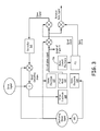
- Figure 3 is a block diagram illustrating the input and output signals for one of the proof masses 102 of the gyroscope 100.
- Figure 4 is a graph illustrating an example output signal from a proof mass 102, 103 of the gyroscope 100.
- respective AC drive signals are applied to the drive electrodes 104, 105 to induce in-plane motion on the respective proof masses 102, 103 (block 202).
- the in-plane motion of the respective proof masses 102, 103 induces an in-plane signal (motor pickoff signal) on the in-plane motor pickoff electrode 106.
- the control electronics 112 are coupled to the motor pickoff electrode 106 and configured to process the in-plane signal to adjust the AC drive signals to maintain a desired magnitude and frequency (motor frequency) for the in-plane motion of the proof masses 102, 103.
- the drive signal has a frequency of half the motor frequency, such as a drive signal having a frequency of 5 kHz with a motor frequency of 10 kHz.
- Respective voltages are applied between the sense electrodes 107-110 and their corresponding proof masses 102, 103 in order to sense out-of-plane motion of the proof masses 102, 103 (blocks 204, 206).
- a positive delta-v volts can be applied between the first proof mass 102 and the first sense electrode 107 proximate a first surface 114 of the first proof mass 102 (block 204) and a negative delta-v volts can be applied between the first proof mass 102 and the second sense electrode 108 proximate a second surface 115 of the first proof mass 102 (block 206).
- the voltage difference between the first and second sense electrode 107, 108 and the first proof mass 102 induces an out-of-plane signal on the first proof mass 102 when the first proof mass 102 moves out-of-plane (i.e., towards and away from the first and second sense electrodes 107, 108).
- the control electronics 112 are coupled to the first proof mass 102 and configured to process the out-of-plane signal to determine a rotation rate for the proof mass 102 among other things. Voltage differences are also applied between the third and fourth sense electrodes 109, 110 and the second proof mass 103 to induce out-of-plane motion on the second proof mass 103 in a similar manner.
- the proof masses 102, 103 are electrically coupled via the mechanical flexure 111.
- a single out-of-plane signal is generated by the motion of both proof masses 102, 103.
- multiple out-of-plane signals are generated and are blended together in the control electronics 112.
- the blended out-of-plane signals can be processed in the same manner as described herein for the single out-of-plane signal.
- the voltages on the third and fourth sense electrodes 109, 110 are opposite that of the voltages on the first and second sense electrodes 107, 108. That is, the voltage applied to the sense electrode on a given side of its proof mass 102 is opposite the sense electrode on that side of the other proof mass 103.
- the voltage difference applied between the first sense electrode 107 and the first proof mass 102 is positive delta-v
- the voltage difference applied between the third sense electrode 109 and the second proof mass 103 is negative delta-v
- the first sense electrode 107 is proximate the first surface 114 of the first proof mass 102
- the third sense electrode 109 is proximate the first surface 116 of the second proof mass 103
- the first surface 114 of the first proof mass 102 and the first surface 116 of the second proof mass 103 face the same direction.
- the voltage difference applied between the second sense electrode 108 and the first proof mass 102 is negative delta-v
- the voltage difference applied between the fourth sense electrode 110 and the second proof mass 103 is positive delta-v
- the second sense electrode 108 is proximate the second surface 115 of the first proof mass 102
- the fourth sense electrode 110 is proximate the second surface 117 of the second proof mass 103
- the second surface 115 of the first proof mass 102 and the second surface 117 of the second proof mass 103 face the same direction.
- the voltage difference between the sense electrodes 107-110 and their respective proof masses 102, 103 can cause bias errors in the out-of-plane signal.
- the voltage applied between the sense electrodes 107-110 and their respective proof mass 102, 103 is oscillated between positive delta-v and negative delta-v.
- a first oscillating sense signal applied to the first sense electrode 107 can oscillate between applying positive delta-v volts and negative delta-v volts to the first sense electrode 107.
- a second oscillating sense signal applied to the second sense electrode 108 can oscillate between applying negative delta-v volts and positive delta-v volts to the second sense electrode 108.
- the first oscillating sense signal and the second oscillating sense signal can be 180 degrees out-of-phase such that when positive delta-v volts is applied to the first sense electrode 107, negative delta-v volts is applied to the second sense electrode 108 and when negative delta-v volts is applied to the first sense electrode 107, positive delta-v volts is applied to the second sense electrode 108.
- the voltage difference applied between the sense electrodes 107, 108 and the first proof mass 102 can be maintained while the sign of that voltage difference is alternated on each sense electrode 107, 108. This can help reduce bias errors caused by the voltage difference between the sense electrodes 107, 108 and the first proof mass 102 by effectively averaging out effects on the proof masses 102, 103 caused by the voltage differences of the sense electrodes 107-110.
- the voltage difference applied to the third and fourth sense electrodes 109, 110 can be oscillated in synchronization with the oscillation of the first and second sense electrodes 107, 108.
- the oscillation sense signal applied to the third sense electrode 109 can be 180 degrees out-of-phase with the first oscillating sense signal applied to the first sense electrode 107.
- the second oscillating sense signal which is applied to the second sense electrode 108, can be applied to the third sense electrode 109.
- the first oscillating sense signal can be applied to the fourth sense electrode 110 such that the voltage is 180 degrees out-of-phase with the voltage on the third sense electrode 109.
- the first and second oscillating sense signals comprise square waves such that the voltage on a given sense electrode 107-110 is held at positive delta-v volts for a time period of a quarter period and is then switched to negative delta-v volts for a time period of another quarter period.
- the square wave causes the voltage on the sense electrode 107-110 to alternate in this manner between positive delta-v and negative delta-v volts.
- the first and second oscillating sense signals comprise sine waves (i.e., AC signals), such that the voltage on a given sense electrode 107-110 is incrementally varied between positive delta-v and negative delta-v volts according to the sine wave.
- delta-v is commonly referred to as the scale factor for the gyroscope 100.
- delta-v can be set and/or adjusted over time as desired to implement the desired scale factor for the gyroscope 100.
- delta-v is in the range of 1 to 10 volts, and in a particular example is about 5 volts.
- the frequency of the first and second oscillating sense signals can be a frequency of up to 100 kHz, and in a particular example is a frequency of about 50 kHz.
- the frequency of the first and second oscillating sense signals is selected to be sufficiently spaced from the motor freuqency (for example, 10 kHz) of the proof masses 102, 103, such that the oscillation of the voltage on the first and second sense electrodes 107, 108 does not induce motion on the proof masses 102, 103.
- the frequency of oscillation is selected to be high enough that sufficient charge is unlikely to accumulate while a voltage on a sense electrode 107-110 is at a given sign. This is particularly so in examples where a square wave is used, as in such examples the voltage is held at large voltage differentials for a longer period of time.
- a high frequency can also be advantageous in examples where a sine wave is used.
- FIG. 3 a block diagram of a portion of the gyroscope 100 illustrating, among other things, a quad cancelling signal applied to one of the proof masses 102 is shown.
- a quad cancelling signal can be applied to reduce quadrature motion caused by mechanical asymmetry in the gyroscope 100 (block 208).
- the quad cancelling signal can be applied to an in-plane electrode (in-plane with the proof masses 102, 103) for each proof mass 102, 103 respectively.
- the in-plane electrode for the respective proof mass 102, 103 is the drive electrode 104, 105, such that the sum of a quad cancelling signal and an AC drive signal is applied to each drive electrode 104, 105.
- in-plane electrodes separate from the drive electrode 104, 105 can be used.
- quadrature motion is observable in the out-of-plane signal from the proof mass(es) 102.
- Quadrature motion can be distinguished from out-of-plane motion due to rotation, because the two motions produce signals that are 90 degrees out-of-phase.
- Different phase demodulation can be used to distinguish between the quad signal and the rate signal.
- the out-of-plane signal is demodulated by a rate clock (signal) that is in sync (in phase) with the motor motion at the motor frequency to generate a rate signal (block 212), and the out-of-plane signal is demodulated by a quad clock (signal) that is 90 degrees out of the phase with the motor motion (block 212).
- a quad signal corresponding to the quad motion of the proof mass(es) 102 and a rate signal corresponding to the motion due to rotation of the proof mass(es) 102 can be generated.
- the out-of-plane signal is also demodulated by the oscillating sense signal to remove the effects of such oscillating sense signal on the out-of-plane signal (block 210).
- Figure 4 is a graph of the frequency components of an example of the out-of-plane signal.
- the out-of-plane signal primarily has three frequency components, a first component 402 from the oscillating sense signal, and two sidebands 404 therefrom comprising the rate and quad signal.
- the first component 402 is at the frequency of the oscillating sense signal, and can be quite large. This first component 402 can be reduced/removed by the demodulation of the out-of-plane signal with the oscillating sense signal (block 210).
- the sideband components 404 are spaced from the first component 402 on each side by a frequency equal to the motor frequency.
- the quad signal is significantly larger than the rate signal in these sideband components 404. Due to the significantly larger quad signal, demodulation of the out-of-plane signal with the rate clock may not be sufficient to remove enough quad signal component from the sidebands 404 to generate an accurate rate signal.
- the quad signal is fed back through the control electronics 112 to generate the quad cancelling signal mentioned above (block 208).
- the control electronics 112 generate a bias voltage based on the magnitude of the quad signal. This bias voltage adjusts the magnitude of the quad cancelling signal to reduce (e.g., minimize) quadrature motion observable in the out-of-plane signal.
- the quadrature motion is caused by the mechanical asymmetry in combination with the voltage differential applied by the sense electrodes 107-110.
- the quad cancelling signal oscillates in sync with the oscillation of the oscillating sense signals.
- the quad cancelling signal can oscillate in sync with either the first or second oscillating sense signals depending on the direction of the desired bias to be applied.
- the bias voltage is mixed with the oscillating sense signal to control how much of the oscillating sense signal is applied to the in-plane electrode(s).
- the resulting quad cancelling signal is applied to the in-plane electrode (e.g., the drive electrodes 104, 105) to reduce the quad motion of the proof mass(es) 102, 103 and therefore to reduce the quad signal in the out-of-plane signal (block 208).
- the quad cancelling signal is summed with the drive signal and the sum of both signals is applied to the drive electrode 104.
- Figure 3 illustrates only a single proof mass 102 and a single in-plane electrode (drive electrode 104), it should be understood that a corresponding quad cancellation signal is applied to the other proof mass 103 in examples including such other proof mass 103.
- a first quad cancelling signal applied to a first in-plane electrode (e.g., first drive electrode 104) for the first proof mass 102 is 180 degrees out-of-phase with a second quad cancelling signal applied to a second in-plane electrode (e.g., second drive electrode 105) for the second proof mass 103.
- the quad cancelling signals have the same form as the oscillating sense signals, such that in examples where the oscillating sense signals are square waves, the quad cancelling signals are also square waves, and in examples where the oscillating sense signals are sine waves, the quad cancelling signals are also sine waves.
- the proof masses 102, 103 may have a sufficiently symmetric construction such that significant quad motion is not generated and a quad cancelling signal is not needed.
- control electronics 112 are configured to synchronously demodulate the out-of-plane signal at the motor frequency (rate clock) to generate a rate signal as mentioned above (block 214).
- the control electronics 112 can include any suitable hardware and/or software for implementing the above described functions including a combination of analog and digital components.
- demodulation of the out-of-plane signal is accomplished with one or more suitable processing devices such as a general purpose or special purpose processor.
- Instructions to implement the above functions can be stored one or in an appropriate storage medium (e.g., flash memory or other nonvolatile memory) from which the instructions can be read by the one or more processing devices.
- the frequency for the oscillating sense signals is selected to be low enough to enable demodulation of the out-of-plane signal by a suitable processing device.
- the gyroscope 100 can be configured to output a signal indicative of a rotation rate thereof.
- Example 1 includes a method for operating a micro-electro-mechanical system (MEMS) tuning fork gyroscope, the method comprising: oscillating a voltage on a first sense electrode out-of-plane from and proximate a first side of a first proof mass between a first voltage and a second voltage at a first frequency; oscillating a voltage on a second sense electrode out-of-plane from and proximate a second side of the first proof mass between the first voltage and the second voltage at the first frequency and 180 degrees out-of-phase with the voltage on the first sense electrode; and generating a rate signal corresponding to a rotation rate of the first proof mass by first demodulating an out-of-plane signal from the first proof mass at the first frequency and second demodulating the out-of-plane signal in phase with in-plane motion of the first proof mass.
- MEMS micro-electro-mechanical system
- Example 2 includes the method of Example 1, wherein oscillating a voltage on the first sense electrode and oscillating a voltage on the second sense electrode comprises oscillating the voltage on the first sense electrode and oscillating the voltage on the second sense electrode according to square waves such that the voltage on the first sense electrode and the second sense electrode alternates between the first voltage and the second voltage.
- Example 3 includes the method of Example 1, wherein oscillating a voltage on the first sense electrode and oscillating a voltage on the second sense electrode comprises oscillating the voltage on the first sense electrode and oscillating the voltage on the second sense electrode according to sine waves.
- Example 4 includes the method of any of Examples 1-3, wherein the first voltage is delta-v volts above a DC voltage level of the first proof mass and the second voltage is delta-v volts below the DC voltage level of the first proof mass.
- Example 5 includes the method of Example 4, wherein delta-v volts is in the range of 1-10 volts.
- Example 6 includes the method of any of Examples 1-5, comprising applying a first AC drive signal to a first in-plane electrode that is in-plane with the first proof mass in order to induce in-plane drive motion on the first proof mass; applying a first quad cancelling signal to the first in-plane electrode, the first quad cancelling signal having the first frequency and in-phase with either the voltage on the first sense electrode or the voltage on the second sense electrode.
- Example 7 includes the method of Example 6, comprising: oscillating a voltage on a third sense electrode out-of-plane from and proximate a first side of a second proof mass between the first voltage and the second voltage at the first frequency and 180 degrees out-of phase with the voltage on the first sense electrode, wherein the second proof mass is in-plane with the first proof mass and the first side of the second proof mass faces the same direction as the first side of the first proof mass; oscillating a voltage on a fourth sense electrode out-of-plane from and proximate a second side of the second proof mass between the first voltage and the second voltage at the first frequency and 180 degrees out-of-phase with the voltage on the third sense electrode; wherein the first proof mass and the second proof mass are electrically coupled together; applying a second AC drive signal to a second in-plane electrode that is in-plane with the second proof mass in order to induce in-plane drive motion on the second proof mass; and applying a second quad cancelling signal to the second in-plane electrode, the second
- Example 8 includes the method of any of Examples 6 or 7, comprising: generating a quad signal by first demodulating the out-of-plane signal from the first proof mass at the first frequency and second demodulating the out-of-plane signal at a 90 degree out-of-phase from the in-plane motion of the first proof mass; determining a motor bias value based on the magnitude of the quad signal; and mixing the motor bias value with a signal having the first frequency and in-phase with either the voltage on the first sense electrode or the voltage on the second sense electrode to generate the first quad cancelling signal.
- Example 9 includes the method of any of Examples 1-8, wherein the first frequency is in the range of 1 Hz to 100 KHz.
- Example 10 includes a micro-electro-mechanical system (MEMS) tuning fork gyroscope comprising: a first planar proof mass defining a first surface and a second surface; a first sense electrode out-of-plane from the first proof mass and proximate the first surface; a second sense electrode out-of-plane from the first proof mass and proximate the second surface; a first in-plane electrode having a comb that interleaves with a comb on the second planar proof mass; and control electronics configured to: apply a first AC drive signal to the first in-plane electrode to induce in-plane drive motion on the first proof mass; apply a first oscillating voltage to the first sense electrode and a second oscillating voltage to the second sense electrode, wherein the first oscillating voltage oscillates between a first voltage and a second voltage at a first frequency, and wherein the second oscillating voltage oscillates between the first voltage and the second voltage at the first frequency and 180 degrees out-of-phase from the first oscil
- Example 11 includes the MEMS tuning fork gyroscope of Example 10, wherein the first oscillating voltage and the second oscillating voltage oscillate according to square waves such that the voltage on the first sense electrode and the second sense electrode alternates between the first voltage and the second voltage.
- Example 12 includes the MEMS tuning fork gyroscope of Example 10, wherein the first oscillating voltage and the second oscillating voltage oscillate according to sine waves.
- Example 13 includes the MEMS tuning fork gyroscope of any of Examples 10-12, wherein the first voltage is delta-v volts above a DC voltage level of the first proof mass and the second voltage is delta-v volts below the DC voltage level of the first proof mass.
- Example 14 includes the MEMS tuning fork gyroscope of Example 13, wherein delta-v volts is in the range of 1-10 volts.
- Example 15 includes the MEMS tuning fork gyroscope of any of Examples 10-14, wherein the control electronics are configured to apply a first quad cancelling signal to the first in-plane electrode, the first quad cancelling signal having the first frequency and in-phase with either the voltage on the first sense electrode or the voltage on the second sense electrode.
- Example 16 includes the MEMS tuning fork gyroscope of Example 15, comprising: a second planar proof mass in-plane with and electrically coupled to the first proof mass and defining a third surface and a fourth surface, wherein the third surface faces the same direction as the first surface; a third sense electrode out-of-plane from the second proof mass and proximate the third surface; a fourth sense electrode out-of-plane from the second proof mass and proximate the fourth surface; and a second in-plane electrode having a comb that interleaves with a comb of the second planar proof mass; wherein the control electronics are configured to: apply a second AC drive signal to the second in-plane electrode to induce in-plane drive motion on the first proof mass; apply a third oscillating voltage to the third sense electrode and a fourth oscillating voltage to the fourth sense electrode, wherein the third oscillating voltage oscillates between the first voltage and the second voltage at the first frequency and 180 out-of-phase from the first oscillating voltage; and
- Example 17 includes the MEMS tuning fork gyroscope of any of Examples 15 or 16, wherein the control electronics are configured to: generate a quad signal by first demodulating the out-of-plane signal from the first proof mass at the first frequency and second demodulating the out-of-plane signal at a 90 degree out-of-phase from the in-plane motion of the first proof mass; determine a motor bias value based on the magnitude of the quad signal; and mix the motor bias value with a signal having the first frequency and in-phase with either the voltage on the first sense electrode or the voltage on the second sense electrode to generate the first quad cancelling signal.
- Example 18 includes the MEMS tuning fork gyroscope of any of Examples 10-17, wherein the first frequency is in the range of 1 Hz to 100 KHz.
- Example 19 includes a micro-electro-mechanical system (MEMS) tuning fork gyroscope comprising: a first planar proof mass defining a first surface and a second surface; a first sense electrode out-of-plane from the first proof mass and proximate the first surface; a second sense electrode out-of-plane from the first proof mass and proximate the second surface; a first in-plane electrode having a comb that interleaves with a comb on the second planar proof mass; a second planar proof mass in-plane with the first proof mass and defining a third surface and a fourth surface, wherein the third surface faces the same direction as the first surface; a third sense electrode out-of-plane from the second proof mass and proximate the third surface; a fourth sense electrode out-of-plane from the second proof mass and proximate the fourth surface; a second in-plane electrode having a comb that interleaves with a comb of the second planar proof mass; and control
- Example 20 includes the MEMS tuning fork gyroscope of Example 19, wherein the control electronics are configured to: apply a first quad cancelling signal to the first in-plane electrode, the first quad cancelling signal having the first frequency and in-phase with either the first oscillating voltage or the second oscillating voltage; and apply a second quad cancelling signal to the second in-plane electrode, the second quad cancelling signal having the first frequency and 180 degrees out-of-phase with the first quad cancelling signal.
Landscapes
- Engineering & Computer Science (AREA)
- Physics & Mathematics (AREA)
- General Physics & Mathematics (AREA)
- Radar, Positioning & Navigation (AREA)
- Remote Sensing (AREA)
- Signal Processing (AREA)
- Gyroscopes (AREA)
- Pressure Sensors (AREA)
- Micromachines (AREA)
Abstract
Description
- A micro-electro-mechanical system (MEMS) tuning fork gyroscope can have bias mechanisms due to interaction between the proof masses and the sense electrodes. One form of bias is caused by sense bias asymmetry, which is an offset in sense bias voltage due to material properties. This asymmetry can cause a displacement of the two proof masses relative to each other which, in turn, causes drive comb disengagement, lift to drive, and finally bias. Another form of bias is charging of exposed glass which causes time varying bias.
- Embodiments of the subject application provide a method for operating a micro-electro-mechanical system (MEMS) tuning fork gyroscope. The method includes oscillating a voltage on a first sense electrode out-of-plane from and proximate a first side of a first proof mass between a first voltage and a second voltage at a first frequency. The method also includes oscillating a voltage on a second sense electrode out-of-plane from and proximate a second side of the first proof mass between the first voltage and the second voltage at the first frequency and 180 degrees out-of-phase with the voltage on the first sense electrode. The method also includes generating a rate signal corresponding to a rotation rate of the first proof mass by first demodulating an out-of-plane signal from the first proof mass at the first frequency and second demodulating the out-of-plane signal in phase with in-plane motion of the first proof mass.
- Understanding that the drawings depict only exemplary embodiments and are not therefore to be considered limiting in scope, the exemplary embodiments will be described with additional specificity and detail through the use of the accompanying drawings, in which:
-
Figure 1A is a plan view of an example of a MEMS tuning fork gyroscope. -
Figure 1B is a cross-sectional view of an example of proof masses and associated electrodes from the gyroscope ofFigure 1A . -
Figure 2 is a flow chart illustrating an example method of operation of the MEMS tuning fork gyroscope ofFigures 1A and1B . -
Figure 3 is a block diagram of a portion of the gyroscope ofFigures 1A and1B . -
Figure 4 is a graph of the frequency components of an example output signal from a proof mass in the gyroscope ofFigures 1A ,1B , and3 . - In accordance with common practice, the various described features are not drawn to scale but are drawn to emphasize specific features relevant to the exemplary embodiments.
- The embodiments described below relate to methods and systems for oscillating the voltage on the sense electrodes (for example, sense plates) of a MEMS tuning fork gyroscope in order to reduce bias caused by the voltage applied thereto. A quad cancelling signal based on the oscillating voltage can also be applied to an in-plane electrode(s) in order to affect a proper motor bias on the proof masses.
-
Figure 1A is a plan view of a micro-electro-mechanical system (MEMS) tuning fork gyroscope 100 comprising a pair ofproof masses control electronics 112. Eachproof mass respective proof masses proof mass plane drive electrode proof mass motor pickoff electrode 106. -
Figure 1B is a cross-sectional view of theproof masses upper sense electrodes proof masses upper sense electrode first surface respective proof mass lower sense electrodes proof masses lower sense electrode second surface respective proof mass proof mass proof masses motor pickoff electrode 106 and the out-of-plane sense electrodes 107-110. In the example shown inFigure 1A , the twoproof masses more flexures 111. In other examples however, the twoproof masses - The operation of the gyroscope 100 is described with respect to
Figures 2 ,3 , and4 .Figure 2 is a flow chart illustrating anexample method 200 of operation of the gyroscope 100.Figure 3 is a block diagram illustrating the input and output signals for one of theproof masses 102 of the gyroscope 100.Figure 4 is a graph illustrating an example output signal from aproof mass - In operation, respective AC drive signals are applied to the
drive electrodes respective proof masses 102, 103 (block 202). The in-plane motion of therespective proof masses motor pickoff electrode 106. Thecontrol electronics 112 are coupled to themotor pickoff electrode 106 and configured to process the in-plane signal to adjust the AC drive signals to maintain a desired magnitude and frequency (motor frequency) for the in-plane motion of theproof masses - Respective voltages are applied between the sense electrodes 107-110 and their
corresponding proof masses proof masses 102, 103 (blocks 204, 206). For example, at a given moment in time a positive delta-v volts can be applied between thefirst proof mass 102 and thefirst sense electrode 107 proximate afirst surface 114 of the first proof mass 102 (block 204) and a negative delta-v volts can be applied between thefirst proof mass 102 and thesecond sense electrode 108 proximate asecond surface 115 of the first proof mass 102 (block 206). At this moment in time, there is a 2 times delta-v volt difference between the first andsecond sense electrode second sense electrode first proof mass 102 induces an out-of-plane signal on thefirst proof mass 102 when thefirst proof mass 102 moves out-of-plane (i.e., towards and away from the first andsecond sense electrodes 107, 108). Thecontrol electronics 112 are coupled to thefirst proof mass 102 and configured to process the out-of-plane signal to determine a rotation rate for theproof mass 102 among other things. Voltage differences are also applied between the third andfourth sense electrodes second proof mass 103 to induce out-of-plane motion on thesecond proof mass 103 in a similar manner. In the example shown inFigure 1A , theproof masses mechanical flexure 111. In such examples, a single out-of-plane signal is generated by the motion of bothproof masses more proof masses control electronics 112. In such examples, the blended out-of-plane signals can be processed in the same manner as described herein for the single out-of-plane signal. - In an example, the voltages on the third and
fourth sense electrodes second sense electrodes proof mass 102 is opposite the sense electrode on that side of theother proof mass 103. When the voltage difference applied between thefirst sense electrode 107 and thefirst proof mass 102 is positive delta-v, the voltage difference applied between thethird sense electrode 109 and thesecond proof mass 103 is negative delta-v, wherein thefirst sense electrode 107 is proximate thefirst surface 114 of thefirst proof mass 102 and thethird sense electrode 109 is proximate thefirst surface 116 of thesecond proof mass 103, and wherein thefirst surface 114 of thefirst proof mass 102 and thefirst surface 116 of thesecond proof mass 103 face the same direction. Similarly, if when the voltage difference applied between thesecond sense electrode 108 and thefirst proof mass 102 is negative delta-v, the voltage difference applied between thefourth sense electrode 110 and thesecond proof mass 103 is positive delta-v, wherein thesecond sense electrode 108 is proximate thesecond surface 115 of thefirst proof mass 102 and thefourth sense electrode 110 is proximate thesecond surface 117 of thesecond proof mass 103, and wherein thesecond surface 115 of thefirst proof mass 102 and thesecond surface 117 of thesecond proof mass 103 face the same direction. - As mentioned above, the voltage difference between the sense electrodes 107-110 and their
respective proof masses respective proof mass first sense electrode 107 can oscillate between applying positive delta-v volts and negative delta-v volts to thefirst sense electrode 107. Similarly, a second oscillating sense signal applied to thesecond sense electrode 108 can oscillate between applying negative delta-v volts and positive delta-v volts to thesecond sense electrode 108. The first oscillating sense signal and the second oscillating sense signal can be 180 degrees out-of-phase such that when positive delta-v volts is applied to thefirst sense electrode 107, negative delta-v volts is applied to thesecond sense electrode 108 and when negative delta-v volts is applied to thefirst sense electrode 107, positive delta-v volts is applied to thesecond sense electrode 108. Thus, the voltage difference applied between thesense electrodes first proof mass 102 can be maintained while the sign of that voltage difference is alternated on eachsense electrode sense electrodes first proof mass 102 by effectively averaging out effects on theproof masses - The voltage difference applied to the third and
fourth sense electrodes second sense electrodes fourth electrode second electrode third sense electrode 109 can be 180 degrees out-of-phase with the first oscillating sense signal applied to thefirst sense electrode 107. Thus, the second oscillating sense signal, which is applied to thesecond sense electrode 108, can be applied to thethird sense electrode 109. Likewise, the first oscillating sense signal can be applied to thefourth sense electrode 110 such that the voltage is 180 degrees out-of-phase with the voltage on thethird sense electrode 109. - In an example, the first and second oscillating sense signals comprise square waves such that the voltage on a given sense electrode 107-110 is held at positive delta-v volts for a time period of a quarter period and is then switched to negative delta-v volts for a time period of another quarter period. The square wave causes the voltage on the sense electrode 107-110 to alternate in this manner between positive delta-v and negative delta-v volts. In another example, the first and second oscillating sense signals comprise sine waves (i.e., AC signals), such that the voltage on a given sense electrode 107-110 is incrementally varied between positive delta-v and negative delta-v volts according to the sine wave.
- The value for delta-v is commonly referred to as the scale factor for the gyroscope 100. As such, delta-v can be set and/or adjusted over time as desired to implement the desired scale factor for the gyroscope 100. In an example, delta-v is in the range of 1 to 10 volts, and in a particular example is about 5 volts.
- In an example, the frequency of the first and second oscillating sense signals can be a frequency of up to 100 kHz, and in a particular example is a frequency of about 50 kHz. Ideally, the frequency of the first and second oscillating sense signals is selected to be sufficiently spaced from the motor freuqency (for example, 10 kHz) of the
proof masses second sense electrodes proof masses - Referring now to
Figure 3 , a block diagram of a portion of the gyroscope 100 illustrating, among other things, a quad cancelling signal applied to one of theproof masses 102 is shown. In addition to the AC drive signals applied to thedrive electrodes proof masses 102, 103) for eachproof mass respective proof mass drive electrode drive electrode drive electrode - Since quadrature motion is out-of-plane motion, quadrature motion is observable in the out-of-plane signal from the proof mass(es) 102. Quadrature motion can be distinguished from out-of-plane motion due to rotation, because the two motions produce signals that are 90 degrees out-of-phase. Different phase demodulation can be used to distinguish between the quad signal and the rate signal. In particular, the out-of-plane signal is demodulated by a rate clock (signal) that is in sync (in phase) with the motor motion at the motor frequency to generate a rate signal (block 212), and the out-of-plane signal is demodulated by a quad clock (signal) that is 90 degrees out of the phase with the motor motion (block 212). In this way, a quad signal corresponding to the quad motion of the proof mass(es) 102 and a rate signal corresponding to the motion due to rotation of the proof mass(es) 102 can be generated. In addition to demodulation by the rate or quad clock, the out-of-plane signal is also demodulated by the oscillating sense signal to remove the effects of such oscillating sense signal on the out-of-plane signal (block 210).
-
Figure 4 is a graph of the frequency components of an example of the out-of-plane signal. As shown, the out-of-plane signal primarily has three frequency components, afirst component 402 from the oscillating sense signal, and twosidebands 404 therefrom comprising the rate and quad signal. Thefirst component 402 is at the frequency of the oscillating sense signal, and can be quite large. Thisfirst component 402 can be reduced/removed by the demodulation of the out-of-plane signal with the oscillating sense signal (block 210). Thesideband components 404 are spaced from thefirst component 402 on each side by a frequency equal to the motor frequency. Typically, without any quad cancellation, the quad signal is significantly larger than the rate signal in thesesideband components 404. Due to the significantly larger quad signal, demodulation of the out-of-plane signal with the rate clock may not be sufficient to remove enough quad signal component from thesidebands 404 to generate an accurate rate signal. - To reduce the quad signal component of these
sideband components 404, the quad signal is fed back through thecontrol electronics 112 to generate the quad cancelling signal mentioned above (block 208). In particular, thecontrol electronics 112 generate a bias voltage based on the magnitude of the quad signal. This bias voltage adjusts the magnitude of the quad cancelling signal to reduce (e.g., minimize) quadrature motion observable in the out-of-plane signal. - The quadrature motion is caused by the mechanical asymmetry in combination with the voltage differential applied by the sense electrodes 107-110. In order to apply to the proper quad cancelling signal to the in-plane electrode (e.g., drive
electrodes 104, 105) when the voltage on the sense electrodes 107-110 is oscillating, the quad cancelling signal oscillates in sync with the oscillation of the oscillating sense signals. The quad cancelling signal can oscillate in sync with either the first or second oscillating sense signals depending on the direction of the desired bias to be applied. To accomplish this, the bias voltage is mixed with the oscillating sense signal to control how much of the oscillating sense signal is applied to the in-plane electrode(s). - The resulting quad cancelling signal is applied to the in-plane electrode (e.g., the
drive electrodes 104, 105) to reduce the quad motion of the proof mass(es) 102, 103 and therefore to reduce the quad signal in the out-of-plane signal (block 208). In an example, the quad cancelling signal is summed with the drive signal and the sum of both signals is applied to thedrive electrode 104. - Although
Figure 3 illustrates only asingle proof mass 102 and a single in-plane electrode (drive electrode 104), it should be understood that a corresponding quad cancellation signal is applied to theother proof mass 103 in examples including suchother proof mass 103. In such examples, since the third andfourth sense electrodes second electrodes first proof mass 102 is 180 degrees out-of-phase with a second quad cancelling signal applied to a second in-plane electrode (e.g., second drive electrode 105) for thesecond proof mass 103. Moreover, the quad cancelling signals have the same form as the oscillating sense signals, such that in examples where the oscillating sense signals are square waves, the quad cancelling signals are also square waves, and in examples where the oscillating sense signals are sine waves, the quad cancelling signals are also sine waves. In some examples, theproof masses - Since the voltage difference on the
proof masses proof masses control electronics 112 are configured to synchronously demodulate the out-of-plane signal at the motor frequency (rate clock) to generate a rate signal as mentioned above (block 214). - The
control electronics 112 can include any suitable hardware and/or software for implementing the above described functions including a combination of analog and digital components. In an example, demodulation of the out-of-plane signal is accomplished with one or more suitable processing devices such as a general purpose or special purpose processor. Instructions to implement the above functions can be stored one or in an appropriate storage medium (e.g., flash memory or other nonvolatile memory) from which the instructions can be read by the one or more processing devices. In an example, the frequency for the oscillating sense signals is selected to be low enough to enable demodulation of the out-of-plane signal by a suitable processing device. The gyroscope 100 can be configured to output a signal indicative of a rotation rate thereof. - Although the above examples describe a gyroscope with a pair of
proof masses - Example 1 includes a method for operating a micro-electro-mechanical system (MEMS) tuning fork gyroscope, the method comprising: oscillating a voltage on a first sense electrode out-of-plane from and proximate a first side of a first proof mass between a first voltage and a second voltage at a first frequency; oscillating a voltage on a second sense electrode out-of-plane from and proximate a second side of the first proof mass between the first voltage and the second voltage at the first frequency and 180 degrees out-of-phase with the voltage on the first sense electrode; and generating a rate signal corresponding to a rotation rate of the first proof mass by first demodulating an out-of-plane signal from the first proof mass at the first frequency and second demodulating the out-of-plane signal in phase with in-plane motion of the first proof mass.
- Example 2 includes the method of Example 1, wherein oscillating a voltage on the first sense electrode and oscillating a voltage on the second sense electrode comprises oscillating the voltage on the first sense electrode and oscillating the voltage on the second sense electrode according to square waves such that the voltage on the first sense electrode and the second sense electrode alternates between the first voltage and the second voltage.
- Example 3 includes the method of Example 1, wherein oscillating a voltage on the first sense electrode and oscillating a voltage on the second sense electrode comprises oscillating the voltage on the first sense electrode and oscillating the voltage on the second sense electrode according to sine waves.
- Example 4 includes the method of any of Examples 1-3, wherein the first voltage is delta-v volts above a DC voltage level of the first proof mass and the second voltage is delta-v volts below the DC voltage level of the first proof mass.
- Example 5 includes the method of Example 4, wherein delta-v volts is in the range of 1-10 volts.
- Example 6 includes the method of any of Examples 1-5, comprising applying a first AC drive signal to a first in-plane electrode that is in-plane with the first proof mass in order to induce in-plane drive motion on the first proof mass; applying a first quad cancelling signal to the first in-plane electrode, the first quad cancelling signal having the first frequency and in-phase with either the voltage on the first sense electrode or the voltage on the second sense electrode.
- Example 7 includes the method of Example 6, comprising: oscillating a voltage on a third sense electrode out-of-plane from and proximate a first side of a second proof mass between the first voltage and the second voltage at the first frequency and 180 degrees out-of phase with the voltage on the first sense electrode, wherein the second proof mass is in-plane with the first proof mass and the first side of the second proof mass faces the same direction as the first side of the first proof mass; oscillating a voltage on a fourth sense electrode out-of-plane from and proximate a second side of the second proof mass between the first voltage and the second voltage at the first frequency and 180 degrees out-of-phase with the voltage on the third sense electrode; wherein the first proof mass and the second proof mass are electrically coupled together; applying a second AC drive signal to a second in-plane electrode that is in-plane with the second proof mass in order to induce in-plane drive motion on the second proof mass; and applying a second quad cancelling signal to the second in-plane electrode, the second quad cancelling signal having the first frequency and being 180 degrees out-of-phase with the first quad cancelling signal.
- Example 8 includes the method of any of Examples 6 or 7, comprising: generating a quad signal by first demodulating the out-of-plane signal from the first proof mass at the first frequency and second demodulating the out-of-plane signal at a 90 degree out-of-phase from the in-plane motion of the first proof mass; determining a motor bias value based on the magnitude of the quad signal; and mixing the motor bias value with a signal having the first frequency and in-phase with either the voltage on the first sense electrode or the voltage on the second sense electrode to generate the first quad cancelling signal.
- Example 9 includes the method of any of Examples 1-8, wherein the first frequency is in the range of 1 Hz to 100 KHz.
- Example 10 includes a micro-electro-mechanical system (MEMS) tuning fork gyroscope comprising: a first planar proof mass defining a first surface and a second surface; a first sense electrode out-of-plane from the first proof mass and proximate the first surface; a second sense electrode out-of-plane from the first proof mass and proximate the second surface; a first in-plane electrode having a comb that interleaves with a comb on the second planar proof mass; and control electronics configured to: apply a first AC drive signal to the first in-plane electrode to induce in-plane drive motion on the first proof mass; apply a first oscillating voltage to the first sense electrode and a second oscillating voltage to the second sense electrode, wherein the first oscillating voltage oscillates between a first voltage and a second voltage at a first frequency, and wherein the second oscillating voltage oscillates between the first voltage and the second voltage at the first frequency and 180 degrees out-of-phase from the first oscillating voltage; and determine a signal corresponding to a rotation rate of the first proof mass by first demodulating an out-of-plane signal from the first proof mass at the first frequency and second demodulating the out-of-plane signal in phase with in-plane motion of the first proof mass.
- Example 11 includes the MEMS tuning fork gyroscope of Example 10, wherein the first oscillating voltage and the second oscillating voltage oscillate according to square waves such that the voltage on the first sense electrode and the second sense electrode alternates between the first voltage and the second voltage.
- Example 12 includes the MEMS tuning fork gyroscope of Example 10, wherein the first oscillating voltage and the second oscillating voltage oscillate according to sine waves.
- Example 13 includes the MEMS tuning fork gyroscope of any of Examples 10-12, wherein the first voltage is delta-v volts above a DC voltage level of the first proof mass and the second voltage is delta-v volts below the DC voltage level of the first proof mass.
- Example 14 includes the MEMS tuning fork gyroscope of Example 13, wherein delta-v volts is in the range of 1-10 volts.
- Example 15 includes the MEMS tuning fork gyroscope of any of Examples 10-14, wherein the control electronics are configured to apply a first quad cancelling signal to the first in-plane electrode, the first quad cancelling signal having the first frequency and in-phase with either the voltage on the first sense electrode or the voltage on the second sense electrode.
- Example 16 includes the MEMS tuning fork gyroscope of Example 15, comprising: a second planar proof mass in-plane with and electrically coupled to the first proof mass and defining a third surface and a fourth surface, wherein the third surface faces the same direction as the first surface; a third sense electrode out-of-plane from the second proof mass and proximate the third surface; a fourth sense electrode out-of-plane from the second proof mass and proximate the fourth surface; and a second in-plane electrode having a comb that interleaves with a comb of the second planar proof mass; wherein the control electronics are configured to: apply a second AC drive signal to the second in-plane electrode to induce in-plane drive motion on the first proof mass; apply a third oscillating voltage to the third sense electrode and a fourth oscillating voltage to the fourth sense electrode, wherein the third oscillating voltage oscillates between the first voltage and the second voltage at the first frequency and 180 out-of-phase from the first oscillating voltage; and apply a second quad cancelling signal to the second in-plane electrode, the second quad cancelling signal having the first frequency and 180 degrees out-of-phase with the first quad cancelling signal.
- Example 17 includes the MEMS tuning fork gyroscope of any of Examples 15 or 16, wherein the control electronics are configured to: generate a quad signal by first demodulating the out-of-plane signal from the first proof mass at the first frequency and second demodulating the out-of-plane signal at a 90 degree out-of-phase from the in-plane motion of the first proof mass; determine a motor bias value based on the magnitude of the quad signal; and mix the motor bias value with a signal having the first frequency and in-phase with either the voltage on the first sense electrode or the voltage on the second sense electrode to generate the first quad cancelling signal.
- Example 18 includes the MEMS tuning fork gyroscope of any of Examples 10-17, wherein the first frequency is in the range of 1 Hz to 100 KHz.
- Example 19 includes a micro-electro-mechanical system (MEMS) tuning fork gyroscope comprising: a first planar proof mass defining a first surface and a second surface; a first sense electrode out-of-plane from the first proof mass and proximate the first surface; a second sense electrode out-of-plane from the first proof mass and proximate the second surface; a first in-plane electrode having a comb that interleaves with a comb on the second planar proof mass; a second planar proof mass in-plane with the first proof mass and defining a third surface and a fourth surface, wherein the third surface faces the same direction as the first surface; a third sense electrode out-of-plane from the second proof mass and proximate the third surface; a fourth sense electrode out-of-plane from the second proof mass and proximate the fourth surface; a second in-plane electrode having a comb that interleaves with a comb of the second planar proof mass; and control electronics configured to: apply a first AC drive signal to the first in-plane electrode to induce in-plane drive motion on the first proof mass; apply a second AC drive signal to the second in-plane electrode to induce in-plane drive motion on the first proof mass; apply a first oscillating voltage to the first sense electrode and a second oscillating voltage to the second sense electrode, wherein the first oscillating voltage oscillates between a first voltage and a second voltage at a first frequency, and wherein the second oscillating voltage oscillates between the first voltage and the second voltage at the first frequency and 180 degrees out-of-phase from the first oscillating voltage; apply the first oscillating voltage to the fourth sense electrode and the second oscillating voltage to the third sense electrode; and determine a signal corresponding to a rotation rate of the first and second proof masses by first demodulating an out-of-plane signal from the first and second proof masses at the first frequency and second demodulating the out-of-plane signal in phase with in-plane motion of the first and second proof mass.
- Example 20 includes the MEMS tuning fork gyroscope of Example 19, wherein the control electronics are configured to: apply a first quad cancelling signal to the first in-plane electrode, the first quad cancelling signal having the first frequency and in-phase with either the first oscillating voltage or the second oscillating voltage; and apply a second quad cancelling signal to the second in-plane electrode, the second quad cancelling signal having the first frequency and 180 degrees out-of-phase with the first quad cancelling signal.
Claims (10)
- A method (200) for operating a micro-electro-mechanical system (MEMS) tuning fork gyroscope, the method comprising:oscillating a voltage on a first sense electrode out-of-plane from and proximate a first side of a first proof mass between a first voltage and a second voltage at a first frequency (204);oscillating a voltage on a second sense electrode out-of-plane from and proximate a second side of the first proof mass between the first voltage and the second voltage at the first frequency and 180 degrees out-of-phase with the voltage on the first sense electrode (206); andgenerating a rate signal corresponding to a rotation rate of the first proof mass by first demodulating an out-of-plane signal from the first proof mass at the first frequency (210) and second demodulating the out-of-plane signal in phase with in-plane motion of the first proof mass (214).
- The method (200) of claim 1, wherein oscillating a voltage on the first sense electrode (204) and oscillating a voltage on the second sense electrode (206) comprises oscillating the voltage on the first sense electrode and oscillating the voltage on the second sense electrode according to square waves such that the voltage on the first sense electrode and the second sense electrode alternates between the first voltage and the second voltage.
- The method (200) of claim 1, wherein oscillating a voltage on the first sense electrode (204) and oscillating a voltage on the second sense electrode (206) comprises oscillating the voltage on the first sense electrode and oscillating the voltage on the second sense electrode according to sine waves.
- The method (200) of any of claims 1-3, wherein the first voltage is delta-v volts above a DC voltage level of the first proof mass and the second voltage is delta-v volts below the DC voltage level of the first proof mass.
- The method (200) of claim 4, wherein delta-v volts is in the range of 1-10 volts.
- The method (200) of any of claims 1-5, comprising applying a first AC drive signal to a first in-plane electrode that is in-plane with the first proof mass in order to induce in-plane drive motion on the first proof mass (202);
applying a first quad cancelling signal to the first in-plane electrode, the first quad cancelling signal having the first frequency and in-phase with either the voltage on the first sense electrode or the voltage on the second sense electrode (208). - The method (200) of claim 6, comprising:oscillating a voltage on a third sense electrode out-of-plane from and proximate a first side of a second proof mass between the first voltage and the second voltage at the first frequency and 180 degrees out-of phase with the voltage on the first sense electrode, wherein the second proof mass is in-plane with the first proof mass and the first side of the second proof mass faces the same direction as the first side of the first proof mass;oscillating a voltage on a fourth sense electrode out-of-plane from and proximate a second side of the second proof mass between the first voltage and the second voltage at the first frequency and 180 degrees out-of-phase with the voltage on the third sense electrode;wherein the first proof mass and the second proof mass are electrically coupled together;applying a second AC drive signal to a second in-plane electrode that is in-plane with the second proof mass in order to induce in-plane drive motion on the second proof mass; andapplying a second quad cancelling signal to the second in-plane electrode, the second quad cancelling signal having the first frequency and being 180 degrees out-of-phase with the first quad cancelling signal.
- The method (200) of any of claims 6 or 7, comprising:generating a quad signal by first demodulating the out-of-plane signal from the first proof mass at the first frequency and second demodulating the out-of-plane signal at a 90 degree out-of-phase from the in-plane motion of the first proof mass (212);determining a motor bias value based on the magnitude of the quad signal; andmixing the motor bias value with a signal having the first frequency and in-phase with either the voltage on the first sense electrode or the voltage on the second sense electrode to generate the first quad cancelling signal.
- A micro-electro-mechanical system (MEMS) tuning fork gyroscope (100) comprising:a first planar proof mass (102) defining a first surface (114) and a second surface (115);a first sense electrode (107) out-of-plane from the first proof mass (102) and proximate the first surface (114);a second sense electrode (108) out-of-plane from the first proof mass (102) and proximate the second surface (115);a first in-plane electrode (104) having a comb that interleaves with a comb on the second planar proof mass (103); andcontrol electronics (112) configured to:apply a first AC drive signal to the first in-plane electrode (104) to induce in-plane drive motion on the first proof mass (102);apply a first oscillating voltage to the first sense electrode (107) and a second oscillating voltage to the second sense electrode (108), wherein the first oscillating voltage oscillates between a first voltage and a second voltage at a first frequency, and wherein the second oscillating voltage oscillates between the first voltage and the second voltage at the first frequency and 180 degrees out-of-phase from the first oscillating voltage; anddetermine a signal corresponding to a rotation rate of the first proof mass (102) by first demodulating an out-of-plane signal from the first proof mass (102) at the first frequency and second demodulating the out-of-plane signal in phase with in-plane motion of the first proof mass (102).
- The MEMS tuning fork gyroscope (100) of claim 9, wherein the first voltage is delta-v volts above a DC voltage level of the first proof mass (102) and the second voltage is delta-v volts below the DC voltage level of the first proof mass (102).
Applications Claiming Priority (1)
| Application Number | Priority Date | Filing Date | Title |
|---|---|---|---|
| US13/851,448 US9534896B2 (en) | 2013-03-27 | 2013-03-27 | Oscillating voltage of sense electrodes in a MEMS tuning fork gyroscope |
Publications (2)
| Publication Number | Publication Date |
|---|---|
| EP2784444A2 true EP2784444A2 (en) | 2014-10-01 |
| EP2784444A3 EP2784444A3 (en) | 2015-03-11 |
Family
ID=50342201
Family Applications (1)
| Application Number | Title | Priority Date | Filing Date |
|---|---|---|---|
| EP14160702.8A Withdrawn EP2784444A3 (en) | 2013-03-27 | 2014-03-19 | Method and system for operating a MEMS tuning fork gyroscope |
Country Status (4)
| Country | Link |
|---|---|
| US (1) | US9534896B2 (en) |
| EP (1) | EP2784444A3 (en) |
| JP (1) | JP2014224804A (en) |
| CN (1) | CN104075702A (en) |
Families Citing this family (3)
| Publication number | Priority date | Publication date | Assignee | Title |
|---|---|---|---|---|
| US20200292313A1 (en) * | 2019-03-11 | 2020-09-17 | Honeywell International Inc. | In-plane non-degenerate coriolis vibratory gyroscope |
| IT201900009582A1 (en) * | 2019-06-20 | 2020-12-20 | St Microelectronics Srl | MEMS GYRO WITH REAL-TIME SCALE FACTOR CALIBRATION AND RELATED CALIBRATION METHOD |
| CN112697120B (en) * | 2020-12-10 | 2022-10-18 | 北京自动化控制设备研究所 | Quartz tuning fork gyroscope switch demodulation circuit |
Family Cites Families (12)
| Publication number | Priority date | Publication date | Assignee | Title |
|---|---|---|---|---|
| US5481914A (en) | 1994-03-28 | 1996-01-09 | The Charles Stark Draper Laboratory, Inc. | Electronics for coriolis force and other sensors |
| US6837108B2 (en) | 2002-04-23 | 2005-01-04 | Honeywell International Inc. | Increasing the dynamic range of a MEMS gyroscope |
| US6715353B2 (en) * | 2002-04-25 | 2004-04-06 | Honeywell International, Inc. | MEMS gyroscope with parametric gain |
| US6978673B2 (en) | 2003-02-07 | 2005-12-27 | Honeywell International, Inc. | Methods and systems for simultaneously fabricating multi-frequency MEMS devices |
| US7213458B2 (en) * | 2005-03-22 | 2007-05-08 | Honeywell International Inc. | Quadrature reduction in MEMS gyro devices using quad steering voltages |
| US7426861B2 (en) | 2005-06-15 | 2008-09-23 | The Charles Stark Draper Laboratory, Inc. | Tuning fork gyroscopes, accelerometers, and other sensors with improved scale factor |
| US7444868B2 (en) | 2006-06-29 | 2008-11-04 | Honeywell International Inc. | Force rebalancing for MEMS inertial sensors using time-varying voltages |
| US7444869B2 (en) * | 2006-06-29 | 2008-11-04 | Honeywell International Inc. | Force rebalancing and parametric amplification of MEMS inertial sensors |
| US7552637B2 (en) | 2006-09-19 | 2009-06-30 | Honeywell International Inc. | Torque driving circuit |
| US7984648B2 (en) * | 2008-04-10 | 2011-07-26 | Honeywell International Inc. | Systems and methods for acceleration and rotational determination from an in-plane and out-of-plane MEMS device |
| US8011247B2 (en) * | 2008-06-26 | 2011-09-06 | Honeywell International Inc. | Multistage proof-mass movement deceleration within MEMS structures |
| JP5427199B2 (en) | 2011-03-17 | 2014-02-26 | 日立オートモティブシステムズ株式会社 | Semiconductor physical quantity detection sensor |
-
2013
- 2013-03-27 US US13/851,448 patent/US9534896B2/en active Active
-
2014
- 2014-03-19 EP EP14160702.8A patent/EP2784444A3/en not_active Withdrawn
- 2014-03-26 CN CN201410115619.7A patent/CN104075702A/en active Pending
- 2014-03-26 JP JP2014063940A patent/JP2014224804A/en active Pending
Non-Patent Citations (1)
| Title |
|---|
| None |
Also Published As
| Publication number | Publication date |
|---|---|
| JP2014224804A (en) | 2014-12-04 |
| US20150253138A1 (en) | 2015-09-10 |
| CN104075702A (en) | 2014-10-01 |
| US9534896B2 (en) | 2017-01-03 |
| EP2784444A3 (en) | 2015-03-11 |
Similar Documents
| Publication | Publication Date | Title |
|---|---|---|
| EP2447671B1 (en) | Angular velocity sensor, and synchronous detection circuit used therein | |
| US7216538B2 (en) | Vibratory angular rate sensor | |
| JP2010505102A (en) | Device for measuring yaw rate using vibration sensor | |
| CN102768038A (en) | Adjusting a mems gyroscope to reduce thermally varying bias | |
| JP2008122371A (en) | Force rebalance and parametric amplification of MEMS inertial sensors | |
| JPS6315528B2 (en) | ||
| CN111947637A (en) | Sensor with a sensor element | |
| US9534896B2 (en) | Oscillating voltage of sense electrodes in a MEMS tuning fork gyroscope | |
| JP2016540972A (en) | Improved quadrature compensation | |
| CN115900677A (en) | Method for Correcting Gyroscope Demodulation Phase Drift | |
| CN113639734B (en) | Digital Feedthrough Cancellation System for MEMS Capacitive Gyroscope | |
| RU181082U1 (en) | GYROSCOPE-ACCELROMETER WITH ELECTROSTATIC ROTOR SUSPENSION | |
| RU2568147C1 (en) | Gyro accelerometer with rotor electrostatic suspension and complete primary info | |
| JP3288597B2 (en) | Vibratory gyroscope | |
| JP2013108929A (en) | Vibration type gyro with high accuracy | |
| JP3439861B2 (en) | Vibratory gyroscope | |
| EP0683381B1 (en) | Vibrating gyroscope | |
| JPH08327362A (en) | Vibration type gyro scope | |
| JPH09105637A (en) | Vibrating gyro | |
| JP2869514B2 (en) | 1-axis angular velocity / acceleration sensor | |
| EP4177568A1 (en) | Vibrating-mass sensor system | |
| JP2021060280A (en) | Voltage sensor | |
| JPH05240649A (en) | Vibration type angular velocity detector | |
| JPH0414734B2 (en) | ||
| JP2540256B2 (en) | How to use a vibrating gyro |
Legal Events
| Date | Code | Title | Description |
|---|---|---|---|
| 17P | Request for examination filed |
Effective date: 20140319 |
|
| AK | Designated contracting states |
Kind code of ref document: A2 Designated state(s): AL AT BE BG CH CY CZ DE DK EE ES FI FR GB GR HR HU IE IS IT LI LT LU LV MC MK MT NL NO PL PT RO RS SE SI SK SM TR |
|
| AX | Request for extension of the european patent |
Extension state: BA ME |
|
| PUAI | Public reference made under article 153(3) epc to a published international application that has entered the european phase |
Free format text: ORIGINAL CODE: 0009012 |
|
| PUAL | Search report despatched |
Free format text: ORIGINAL CODE: 0009013 |
|
| AK | Designated contracting states |
Kind code of ref document: A3 Designated state(s): AL AT BE BG CH CY CZ DE DK EE ES FI FR GB GR HR HU IE IS IT LI LT LU LV MC MK MT NL NO PL PT RO RS SE SI SK SM TR |
|
| AX | Request for extension of the european patent |
Extension state: BA ME |
|
| RIC1 | Information provided on ipc code assigned before grant |
Ipc: G01C 19/5726 20120101ALI20150204BHEP Ipc: G01C 19/5621 20120101AFI20150204BHEP |
|
| 17Q | First examination report despatched |
Effective date: 20150615 |
|
| 17Q | First examination report despatched |
Effective date: 20150622 |
|
| RAP1 | Party data changed (applicant data changed or rights of an application transferred) |
Owner name: HONEYWELL INTERNATIONAL INC. |
|
| STAA | Information on the status of an ep patent application or granted ep patent |
Free format text: STATUS: THE APPLICATION IS DEEMED TO BE WITHDRAWN |
|
| 18D | Application deemed to be withdrawn |
Effective date: 20171003 |