EP2784349B1 - Automatic transmission for vehicle - Google Patents
Automatic transmission for vehicle Download PDFInfo
- Publication number
- EP2784349B1 EP2784349B1 EP11876185.7A EP11876185A EP2784349B1 EP 2784349 B1 EP2784349 B1 EP 2784349B1 EP 11876185 A EP11876185 A EP 11876185A EP 2784349 B1 EP2784349 B1 EP 2784349B1
- Authority
- EP
- European Patent Office
- Prior art keywords
- engagement
- automatic transmission
- shift stage
- brake
- shift
- Prior art date
- Legal status (The legal status is an assumption and is not a legal conclusion. Google has not performed a legal analysis and makes no representation as to the accuracy of the status listed.)
- Not-in-force
Links
Images


Classifications
-
- F—MECHANICAL ENGINEERING; LIGHTING; HEATING; WEAPONS; BLASTING
- F15—FLUID-PRESSURE ACTUATORS; HYDRAULICS OR PNEUMATICS IN GENERAL
- F15B—SYSTEMS ACTING BY MEANS OF FLUIDS IN GENERAL; FLUID-PRESSURE ACTUATORS, e.g. SERVOMOTORS; DETAILS OF FLUID-PRESSURE SYSTEMS, NOT OTHERWISE PROVIDED FOR
- F15B15/00—Fluid-actuated devices for displacing a member from one position to another; Gearing associated therewith
- F15B15/02—Mechanical layout characterised by the means for converting the movement of the fluid-actuated element into movement of the finally-operated member
-
- F—MECHANICAL ENGINEERING; LIGHTING; HEATING; WEAPONS; BLASTING
- F16—ENGINEERING ELEMENTS AND UNITS; GENERAL MEASURES FOR PRODUCING AND MAINTAINING EFFECTIVE FUNCTIONING OF MACHINES OR INSTALLATIONS; THERMAL INSULATION IN GENERAL
- F16D—COUPLINGS FOR TRANSMITTING ROTATION; CLUTCHES; BRAKES
- F16D25/00—Fluid-actuated clutches
- F16D25/06—Fluid-actuated clutches in which the fluid actuates a piston incorporated in, i.e. rotating with the clutch
- F16D25/061—Fluid-actuated clutches in which the fluid actuates a piston incorporated in, i.e. rotating with the clutch the clutch having interengaging clutch members
-
- F—MECHANICAL ENGINEERING; LIGHTING; HEATING; WEAPONS; BLASTING
- F16—ENGINEERING ELEMENTS AND UNITS; GENERAL MEASURES FOR PRODUCING AND MAINTAINING EFFECTIVE FUNCTIONING OF MACHINES OR INSTALLATIONS; THERMAL INSULATION IN GENERAL
- F16H—GEARING
- F16H3/00—Toothed gearings for conveying rotary motion with variable gear ratio or for reversing rotary motion
- F16H3/44—Toothed gearings for conveying rotary motion with variable gear ratio or for reversing rotary motion using gears having orbital motion
- F16H3/62—Gearings having three or more central gears
- F16H3/66—Gearings having three or more central gears composed of a number of gear trains without drive passing from one train to another
- F16H3/663—Gearings having three or more central gears composed of a number of gear trains without drive passing from one train to another with conveying rotary motion between axially spaced orbital gears, e.g. RAVIGNEAUX
-
- F—MECHANICAL ENGINEERING; LIGHTING; HEATING; WEAPONS; BLASTING
- F16—ENGINEERING ELEMENTS AND UNITS; GENERAL MEASURES FOR PRODUCING AND MAINTAINING EFFECTIVE FUNCTIONING OF MACHINES OR INSTALLATIONS; THERMAL INSULATION IN GENERAL
- F16H—GEARING
- F16H57/00—General details of gearing
- F16H57/08—General details of gearing of gearings with members having orbital motion
- F16H57/10—Braking arrangements
-
- F—MECHANICAL ENGINEERING; LIGHTING; HEATING; WEAPONS; BLASTING
- F16—ENGINEERING ELEMENTS AND UNITS; GENERAL MEASURES FOR PRODUCING AND MAINTAINING EFFECTIVE FUNCTIONING OF MACHINES OR INSTALLATIONS; THERMAL INSULATION IN GENERAL
- F16H—GEARING
- F16H63/00—Control outputs from the control unit to change-speed- or reversing-gearings for conveying rotary motion or to other devices than the final output mechanism
- F16H63/02—Final output mechanisms therefor; Actuating means for the final output mechanisms
- F16H63/30—Constructional features of the final output mechanisms
- F16H63/3023—Constructional features of the final output mechanisms the final output mechanisms comprising elements moved by fluid pressure
-
- F—MECHANICAL ENGINEERING; LIGHTING; HEATING; WEAPONS; BLASTING
- F16—ENGINEERING ELEMENTS AND UNITS; GENERAL MEASURES FOR PRODUCING AND MAINTAINING EFFECTIVE FUNCTIONING OF MACHINES OR INSTALLATIONS; THERMAL INSULATION IN GENERAL
- F16H—GEARING
- F16H63/00—Control outputs from the control unit to change-speed- or reversing-gearings for conveying rotary motion or to other devices than the final output mechanism
- F16H63/02—Final output mechanisms therefor; Actuating means for the final output mechanisms
- F16H63/30—Constructional features of the final output mechanisms
- F16H2063/3093—Final output elements, i.e. the final elements to establish gear ratio, e.g. dog clutches or other means establishing coupling to shaft
-
- F—MECHANICAL ENGINEERING; LIGHTING; HEATING; WEAPONS; BLASTING
- F16—ENGINEERING ELEMENTS AND UNITS; GENERAL MEASURES FOR PRODUCING AND MAINTAINING EFFECTIVE FUNCTIONING OF MACHINES OR INSTALLATIONS; THERMAL INSULATION IN GENERAL
- F16H—GEARING
- F16H2200/00—Transmissions for multiple ratios
- F16H2200/003—Transmissions for multiple ratios characterised by the number of forward speeds
- F16H2200/0052—Transmissions for multiple ratios characterised by the number of forward speeds the gear ratios comprising six forward speeds
-
- F—MECHANICAL ENGINEERING; LIGHTING; HEATING; WEAPONS; BLASTING
- F16—ENGINEERING ELEMENTS AND UNITS; GENERAL MEASURES FOR PRODUCING AND MAINTAINING EFFECTIVE FUNCTIONING OF MACHINES OR INSTALLATIONS; THERMAL INSULATION IN GENERAL
- F16H—GEARING
- F16H2200/00—Transmissions for multiple ratios
- F16H2200/20—Transmissions using gears with orbital motion
- F16H2200/2002—Transmissions using gears with orbital motion characterised by the number of sets of orbital gears
- F16H2200/2007—Transmissions using gears with orbital motion characterised by the number of sets of orbital gears with two sets of orbital gears
-
- F—MECHANICAL ENGINEERING; LIGHTING; HEATING; WEAPONS; BLASTING
- F16—ENGINEERING ELEMENTS AND UNITS; GENERAL MEASURES FOR PRODUCING AND MAINTAINING EFFECTIVE FUNCTIONING OF MACHINES OR INSTALLATIONS; THERMAL INSULATION IN GENERAL
- F16H—GEARING
- F16H2200/00—Transmissions for multiple ratios
- F16H2200/20—Transmissions using gears with orbital motion
- F16H2200/202—Transmissions using gears with orbital motion characterised by the type of Ravigneaux set
- F16H2200/2023—Transmissions using gears with orbital motion characterised by the type of Ravigneaux set using a Ravigneaux set with 4 connections
-
- F—MECHANICAL ENGINEERING; LIGHTING; HEATING; WEAPONS; BLASTING
- F16—ENGINEERING ELEMENTS AND UNITS; GENERAL MEASURES FOR PRODUCING AND MAINTAINING EFFECTIVE FUNCTIONING OF MACHINES OR INSTALLATIONS; THERMAL INSULATION IN GENERAL
- F16H—GEARING
- F16H2200/00—Transmissions for multiple ratios
- F16H2200/20—Transmissions using gears with orbital motion
- F16H2200/203—Transmissions using gears with orbital motion characterised by the engaging friction means not of the freewheel type, e.g. friction clutches or brakes
- F16H2200/2043—Transmissions using gears with orbital motion characterised by the engaging friction means not of the freewheel type, e.g. friction clutches or brakes with five engaging means
-
- F—MECHANICAL ENGINEERING; LIGHTING; HEATING; WEAPONS; BLASTING
- F16—ENGINEERING ELEMENTS AND UNITS; GENERAL MEASURES FOR PRODUCING AND MAINTAINING EFFECTIVE FUNCTIONING OF MACHINES OR INSTALLATIONS; THERMAL INSULATION IN GENERAL
- F16H—GEARING
- F16H2200/00—Transmissions for multiple ratios
- F16H2200/20—Transmissions using gears with orbital motion
- F16H2200/203—Transmissions using gears with orbital motion characterised by the engaging friction means not of the freewheel type, e.g. friction clutches or brakes
- F16H2200/2064—Transmissions using gears with orbital motion characterised by the engaging friction means not of the freewheel type, e.g. friction clutches or brakes using at least one positive clutch, e.g. dog clutch
-
- F—MECHANICAL ENGINEERING; LIGHTING; HEATING; WEAPONS; BLASTING
- F16—ENGINEERING ELEMENTS AND UNITS; GENERAL MEASURES FOR PRODUCING AND MAINTAINING EFFECTIVE FUNCTIONING OF MACHINES OR INSTALLATIONS; THERMAL INSULATION IN GENERAL
- F16H—GEARING
- F16H2200/00—Transmissions for multiple ratios
- F16H2200/20—Transmissions using gears with orbital motion
- F16H2200/2079—Transmissions using gears with orbital motion using freewheel type mechanisms, e.g. freewheel clutches
- F16H2200/2082—Transmissions using gears with orbital motion using freewheel type mechanisms, e.g. freewheel clutches one freewheel mechanisms
Definitions
- the present invention relates to a vehicle automatic transmission and particularly to an improvement for simplifying a device configuration.
- a multistage vehicle automatic transmission includes multiple engagement elements having an engagement state switched by an oil pressure so as to selectively establish a plurality of shift stages based on a combination of engagement and release of the multiple engagement elements corresponding to an oil pressure supplied from a hydraulic circuit.
- clutches and brakes including wet friction materials have been widely used as the engagement elements in such an automatic transmission, these friction materials have been considered to have a problem of a loss due to drag occurring when these friction materials are not engaged.
- an automatic transmission including the hydraulic engagement elements uses a large number of oil pressures at the times of start, stop, and economy running and therefore results in an increase in size of an oil pump or the necessity to dispose an electric oil pump, which puts a limitation on a configuration.
- an automatic transmission uses a meshing engagement element, i.e., a so-called dog clutch (meshing clutch) as a substitute for a wet friction material.
- a meshing engagement element i.e., a so-called dog clutch (meshing clutch)
- this corresponds to an automatic transmission depicted in Patent Document 1.
- Patent Document 4 discloses a vehicle automatic transmission which, in the opinion of the Examining Division of the European Patent Office, falls within the wording of the pre-characterizing portion of claim 1.
- Patent Document 5 discloses an automatic transmission, which has several shift control elements and several gearwheels which can be engaged via the shift control elements to form a power flow, in which, to establish a transmission ratio in each case at least one of the shift control elements is closed.
- the shift control elements which are engaged during an up-shift are formed as frictional shift control elements, and the shift control elements, which during up-shifts respectively only constitute a shift control element to be disengaged, are made as positive-locking gear elements.
- the present invention was conceived in view of the situations and it is therefore an object of the present invention to provide a vehicle automatic transmission with a simplified device configuration.
- each of the shift stages is established by engagement of two or more engagement elements of the multiple engagement elements, at least one of the multiple engagement elements is a normally closed engagement element engaged when no oil pressure is supplied from the hydraulic circuit, and the normally closed engagement element is a meshing engagement element and, therefore, the limitation on the configuration of the hydraulic circuit becomes smaller and an oil pump can be reduced in size.
- the occurrence of drag can preferably be suppressed by including at least one meshing engagement element engaged when no oil pressure is supplied from the hydraulic circuit.
- Claim 2 provides a vehicle automatic transmission according to claim 1, wherein when a first shift stage having a largest shift ratio of forward shift stages is established in the automatic transmission, at least one of the multiple engagement elements engaged is the normally closed engagement element. Consequently, the automatic transmission can be provided that has a simplified configuration in a practical form. Additionally, a garage shock at the engine start can be reduced.
- Claim 3 provides the vehicle automatic transmission according to claim 1, wherein when a reverse shift stage is established in the automatic transmission, at least one of the multiple engagement elements engaged is the normally closed engagement element. Consequently, the automatic transmission can be provided that has a simplified configuration in a practical form.
- Claim 4 provides the vehicle automatic transmission according to claim 2, wherein when the first shift stage is established in the automatic transmission, at least one of the multiple engagement elements engaged is a normally opened engagement element released when no oil pressure is supplied from the hydraulic circuit. Consequently, the automatic transmission can be provided that has a simplified configuration in a practical form.
- Claim 5 provides the vehicle automatic transmission according to claim 3, wherein when the reverse shift stage is established in the automatic transmission, at least one of the multiple engagement elements engaged is a normally opened engagement element released when no oil pressure is supplied from the hydraulic circuit. Consequently, the automatic transmission can be provided that has a simplified configuration in a practical form.
- Claim 6 provides the vehicle automatic transmission according to any one of claims 1 to 5, wherein two meshing brakes are included as the normally closed engagement elements, and wherein rotating elements fixed to a non-rotating member by engagement of the respective meshing brakes are directly or indirectly coupled to an output rotating member of the automatic transmission. Consequently, the automatic transmission can be provided that has a simplified configuration in a practical form and, additionally, because the output rotating member is fixed to the non-rotating member while no oil pressure is supplied from the hydraulic circuit, the necessity of a configuration for a parking lock is advantageously eliminated.
- the normally closed engagement element is a meshing engagement device (dog clutch) that includes a pair of engagement members having claw portions engaged with each other corresponding to a pair of respective members to be engaged (prevented from relatively rotating) or released (allowed to relatively rotate) and that has an engagement state switched by the pair of the engagement members relatively moved depending on an oil pressure supplied from a hydraulic circuit.
- dog clutch a meshing engagement device
- the normally closed engagement element is an engagement device that includes, for example, a cylinder, a piston disposed to be reciprocable in the cylinder, and a spring biasing the piston in the engagement direction of the claw portions such that the engagement device is engaged when no oil pressure is supplied because the piston is moved in the direction of meshing the claw portions due to a biasing force of the spring, while the engagement device is released when an oil pressure is supplied because the piston is moved in the direction of releasing the meshing of the claw portions against the biasing force of the spring.
- an engagement device that includes, for example, a cylinder, a piston disposed to be reciprocable in the cylinder, and a spring biasing the piston in the engagement direction of the claw portions such that the engagement device is engaged when no oil pressure is supplied because the piston is moved in the direction of meshing the claw portions due to a biasing force of the spring, while the engagement device is released when an oil pressure is supplied because the piston is moved in the direction of releasing the meshing of the claw portions against the biasing force of the spring.
- the normally closed engagement element is preferably a brake engaged to fix a rotating member to a non-rotating member and more preferably a meshing brake.
- the normally closed engagement element is preferably engaged at the first shift stage having the largest shift ratio of the forward shift stages and at the reverse shift stage.
- the automatic transmission engages at least the normally closed engagement element at the first shift stage having the largest shift ratio of the forward shift stages and at the reverse shift stage.
- the normally closed engagement element may be a friction engagement device and produces a certain effect of the present invention in such a form.
- the automatic transmission preferably includes an input clutch (starting clutch) connecting/disconnecting an input rotating member and an output rotating member and engages the input clutch and the normally closed engagement element to establish the first shift stage having the largest shift ratio of the forward shift stages.
- the input clutch is preferably a normally opened engagement element released when no oil pressure is supplied from the hydraulic circuit and more preferably a hydraulic friction engagement device such as a multiplate clutch.
- Fig. 1 is a schematic for explaining a configuration of a vehicle automatic transmission 10 to which the present invention is preferably applied.
- the automatic transmission 10 of this embodiment is a transversely mounted device preferably used in an FF vehicle etc., and has a first transmission portion 14 mainly made up of a single pinion type first planetary gear device 12 and a second transmission portion 20 mainly made up of a double pinion type second planetary gear device 16 and a single pinion type third planetary gear device 18 on the same axis so as to change rotation of an input shaft 22 and output the rotation from an output rotating member 24.
- the input shaft 22 corresponds to an input rotating member and is a turbine shaft of a torque converter 30 rotationally driven by an engine 28 that is an internal combustion engine for generating power of a vehicle in this embodiment.
- the output rotating member 24 corresponds to an output member of the automatic transmission 10 and acts as an output gear, i.e., a differential drive gear, meshed with a differential driven gear (large diameter gear) for transmitting power to a differential gear device not depicted.
- the output of the engine 28 is transmitted through the torque converter 30, the automatic transmission 10, the differential gear device, and a pair of axles acting as a drive shaft to a pair of drive wheels (front wheels).
- the automatic transmission 10 is substantially symmetrically configured relative to a center line and the lower half from the center line is not depicted in Fig. 1 . The same applies to the following description.
- the engine 28 is a drive source (main power source) generating a drive force for running and is an internal combustion engine such as a gasoline engine and a diesel engine combusting fuel to generate a drive force of a vehicle.
- the torque converter 30 includes a pump impeller 30a coupled to a crankshaft of the engine 28, a turbine impeller 30b coupled to the input shaft 22 of the automatic transmission 10, and a stator impeller 30c coupled via a one-way clutch to a housing (transmission case) 26 of the automatic transmission 10 and is a fluid transmission device transmitting the power generated by the engine 28 through fluid to the automatic transmission 10.
- a lockup clutch 32 is a direct clutch disposed between the pump impeller 30a and the turbine impeller 30b and is put into an engaged state, a slip state, or a released state through hydraulic control etc.
- the lockup clutch 32 is put into a completely engaged state to integrally rotate the pump impeller 30a and the turbine impeller 30b.
- the first planetary gear device 12 is a single pinion type planetary gear device including a sun gear S1, a plurality of pinion gears PI, a carrier CA1 supporting the pinion gears P1 in a rotatable and revolvable manner, and a ring gear R1 meshed with the sun gear S1 via the pinion gears P1.
- the second planetary gear device 16 and the third planetary gear device 18 are configured to be a Ravigneaux type with a ring gear R2 (R3) and a carrier CA2 (CA3) integrally configured.
- the second planetary gear device 16 is a double pinion type planetary gear device including a plurality of pinion gears P2 meshed with each other, supporting the pinion gears P2 in a rotatable and revolvable manner by the carrier CA2, and including a sun gear S2 meshed with the ring gear R2 via the pinion gears P2.
- the third planetary gear device 18 is a single pinion type planetary gear device including a plurality of pinion gears P3, supporting the pinion gears P3 in a rotatable and revolvable manner by the carrier CA3, and including a sun gear S3 meshed with the ring gear R3 via the pinion gears P3.
- the sun gear S1 of the first planetary gear device 12 is coupled to the input shaft 22.
- the carrier CA1 of the first planetary gear device 12 and the sun gear S2 of the second planetary gear device 16 are integrally coupled.
- the carrier CA2 of the second planetary gear device 16 (the carrier CA3 of the third planetary gear device 18) is coupled to the output rotating member 24.
- the automatic transmission 10 includes a plurality of engagement elements having an engagement state switched by an oil pressure.
- a first clutch C1 selectively engaging the input shaft 22 and the sun gear S3 of the third planetary gear device 18 is disposed between the input shaft 22 and the sun gear S3.
- a second clutch C2 selectively engaging the input shaft 22 and the ring gear R2 of the second planetary gear device 16 (R3) is disposed between the input shaft 22 and the ring gear R2 (the ring gear R3 of the third planetary gear device 18).
- a second brake B2 selectively engaging the ring gear R2 (R3) to the housing 26 is disposed between the housing 26 and the ring gear R2 of the second planetary gear device 16 (the ring gear R3 of the third planetary gear device 18).
- a third brake B3 selectively engaging the ring gear R1 to the housing 26 is disposed between the housing 26 and the ring gear R1 of the first planetary gear device 12.
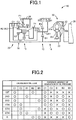
- Fig. 2 is an operation table for explaining the operation state of the engagement elements when a plurality of shift stages is selectively established in the automatic transmission 10 and depicts engagement/release of the engagement elements at each of the shift stages in a left column along with presence/absence of oil pressure supply to the engagement elements at the shift stages in a right column.
- the left column of Fig. 2 summarizes relationship between the shift stages established by the automatic transmission 10 and the operation states of the first clutch C1, the second clutch C2, the first brake B1, the second brake B2, and the third brake B3 (hereinafter referred to as clutches C and brakes B if not particularly distinguished) and " ⁇ " indicates engagement while a blank indicates release.
- the clutches C, the first brake B1, and the third brake B3 included in the automatic transmission 10 are hydraulic friction engagement devices subjected to engagement control by hydraulic actuators, such as multiplate clutches and brakes, and have the engaged and released state switched, and the transient oil pressures at the time of engagement and release controlled, by excitation/non-excitation and current control of a linear solenoid valve included in a hydraulic circuit 60 (see, e.g., Fig. 5 ).
- the second brake B2 is a meshing engagement device (dog clutch) that includes a pair of engagement members having claw portions engaged with each other corresponding to the housing 26 acting as a non-rotating member and the ring gear R2 (R3) acting as a rotating member, and that has an engagement state switched by the pair of the engagement members relatively moved depending on an oil pressure supplied from the hydraulic circuit 60.
- the operation of the second brake B2 will be described with reference to Figs. 5 and 6 .
- the automatic transmission 10 is disposed with a unidirectional clutch F1 allowing the rotation of the ring gear R2 (R3) relative to the housing 26 in one direction and preventing the inverse rotation, in parallel with the second brake B2.
- the unidirectional clutch F1 prevents the relative rotation of the ring gear R2 (R3) to the housing 26, the second brake B2 may not be engaged.
- the unidirectional clutch F1 may not necessarily be disposed.
- the right column of Fig. 2 indicates the presence/absence of the generation of oil pressure (supply of oil pressure from the hydraulic circuit 60) to the engagement elements and " ⁇ " and " ⁇ " indicate the presence of the generation of oil pressure and the absence of the generation of oil pressure, respectively.
- the second brake B2 is associated with the absence of the generation of oil pressure when being engaged in accordance with the shift stages, and is associated with the presence of the generation of oil pressure when being released. Therefore, the second brake B2 is a normally closed engagement element engaged when no oil pressure is supplied from the hydraulic circuit 60 and released when an oil pressure is supplied.
- the clutches C, the first brake B1, and the third brake B3 are associated with the presence of the generation of oil pressure when being engaged in accordance with the shift stages, and are associated with the absence of the generation of oil pressure when being released. Therefore, the clutches C, the first brake B1, and the third brake B3 are normally opened engagement elements released when no oil pressure is supplied from the hydraulic circuit 60 and engaged when an oil pressure is supplied.
- the automatic transmission 10 has six forward shift stages from a first shift stage “1st” to a sixth shift stage “6th” and a reverse shift stage of a reverse shift stage “R” established depending on a combination of the coupling states of the rotating elements (the sun gears S1 to S3, the carriers CA1 to CA3, the ring gears R1 to R3) of the first transmission portion 14 and the second transmission portion 20.
- the first shift stage "1st” having the largest shift ratio ⁇ is established by the engagement of the first clutch C1 and the second brake B2.
- the second shift stage "2nd” having a shift ratio ⁇ smaller than the first shift stage is established by the engagement of the first clutch C1 and the first brake B1.
- the third shift stage “3rd” having a shift ratio ⁇ smaller than the second shift stage is established by the engagement of the first clutch C1 and the third brake B3.
- the fourth shift stage “4th” having a shift ratio ⁇ smaller than the third shift stage is established by the engagement of the first clutch C1 and the second clutch C2.
- the fifth shift stage “5th” having a shift ratio ⁇ smaller than the fourth shift stage is established by the engagement of the second clutch C2 and the third brake B3.
- the sixth shift stage “6th” having the smallest shift ratio ⁇ is established by the engagement of the second clutch C2 and the first brake B1.
- a reverse shift stage “Rev” is established by the engagement of the second brake B2 and the third brake B3.
- the automatic transmission 10 is configured such that a neutral state is achieved by releasing all of the clutches C and the brakes B. Since the automatic transmission 10 of this embodiment is disposed with the unidirectional clutch F1 in parallel with the second brake B2 establishing the first shift stage "1st", the second brake B2 may not necessarily be engaged at the time of start (time of acceleration).
- Fig. 3 is a collinear diagram capable of representing on straight lines the relative relationships of the rotation speeds of the rotating elements having a different coupling state for each shift stage in the automatic transmission 10.
- the collinear diagram of Fig. 3 has two-dimensional coordinates indicative of a relative relationship of the gear ratios ⁇ of the planetary gear devices 12, 16, and 18 in the horizontal axis direction and indicative of a relative rotation speed in the vertical axis direction.
- a horizontal line X1 indicates a zero rotation speed.
- An upper horizontal line X2 indicates a rotation speed "1.0", i.e., a rotation speed N IN of the input shaft 22.
- Y1, Y2, Y3, Y4, Y5, Y6, and Y7 indicates relative rotation speeds of the sun gear S1 of the first planetary gear device 12, the carrier CA1, the ring gear R1, the sun gear S2 of the second planetary gear device 16, the ring gear R2 (R3), the carrier CA2 (CA3), and the sun gear S3 of the third planetary gear device 18, respectively.
- the intervals between the vertical lines Y1 to Y7 are determined depending on the gear ratios ⁇ 1, ⁇ 2, and ⁇ 3 of the planetary gear devices 12, 16, and 18.
- the interval corresponding to "1" is set between the sun gear S and the carrier CA
- the interval corresponding to "p" is set between the carrier CA and the ring gear R.
- the input shaft 22 acting as the input rotating member is selectively coupled via the first clutch C1 to the sun gear S3 and is selectively coupled via the second clutch C2 to the ring gear R2 (R3).
- the carrier CA1 and the sun gear S2 coupled to each other are selectively coupled via the first brake B1 to the housing 26 that is the non-rotating member.
- the ring gear R2 (R3) is selectively coupled via the second brake B2 to the housing 26.
- the ring gear R1 is selectively coupled via the third brake B3 to the housing 26.
- the sun gear S1 is coupled to the input shaft 22.
- the carrier CA2 (CA3) is coupled to the output rotating member 24.
- the relative relationships of the rotation speeds of the rotating elements are defined depending on a combination of engagement and release of the clutches C and the brakes B at the time of establishment of the shift stages.
- the relationship corresponding to the first shift stage "1st” is indicated by a straight line L1.
- the relationship corresponding to the second shift stage “2nd” is indicated by a straight line L2.
- the relationship corresponding to the third shift stage “3rd” is indicated by a straight line L3.
- the relationship corresponding to the fourth shift stage "4th” is indicated by a straight line L4.
- the relationship corresponding to the fifth shift stage "5th” is indicated by a straight line L5.
- the relationship corresponding to the sixth shift stage "6th" is indicated by a straight line L6.
- the relationship corresponding to the reverse shift stage "R” is indicated by a straight line LR.
- the straight lines L1 to L6 and LR are necessarily straight lines between the planetary gear devices 12, 16, and 18; however, the rotation speeds of the rotating elements in the planetary gear devices 12, 16, and 18 are equally represented depending on the engagement states of the clutches C and the brakes B so as to completely represent the relative rotation speeds of the seven rotating elements of the automatic transmission 10 at the shift stages.
- the rotation speed of the output rotating member 24 at the first shift stage "1st” is indicated by an intersection between the straight line L1 defined when the first clutch C1 and the second brake B2 are engaged and the vertical line Y6 indicative of the rotation speed of the carrier CA2 (CA3) coupled to the output rotating member 24.
- the rotation speed of the output rotating member 24 at the second shift stage "2nd” is indicated by an intersection between the straight line L2 defined when the first clutch C1 and the first brake B1 are engaged and the vertical line Y6.
- the rotation speed of the output rotating member 24 at the third shift stage “3rd” is indicated by an intersection between the straight line L3 defined when the first clutch C1 and the third brake B3 are engaged and the vertical line Y6.
- the rotation speed of the output rotating member 24 at the fourth shift stage “4th” is indicated by an intersection between the straight line L4 defined when the first clutch C1 and the second clutch C2 are engaged and the vertical line Y6.
- the rotation speed of the output rotating member 24 at the fifth shift stage “5th” is indicated by an intersection between the straight line L5 defined when the second clutch C2 and the third brake B3 are engaged and the vertical line Y6.
- the rotation speed of the output rotating member 24 at the sixth shift stage "6th” is indicated by an intersection between the straight line L6 defined when the second clutch C2 and the first brake B1 are engaged and the vertical line Y6.
- the rotation speed of the output rotating member 24 at the reverse shift stage “R” is indicated by an intersection between the straight line LR defined when the second brake B2 and the third brake B3 are engaged and the vertical line Y6.
- Fig. 4 is a partial cross-sectional view of a partial configuration of the automatic transmission 10 taken along a plane including a center axis for explaining configurations of the second brake B2 etc.
- the second brake B2 includes a cylinder portion 34 formed on the inner circumferential side of the housing 26, a piston 36 disposed in the cylinder portion 34 to be reciprocable in the direction of a center axis CE of the automatic transmission 10, and a spring 38 biasing the piston 36 in the engagement direction of claw portions 40 and 44 described later.
- the claw portion 40 is formed at an end portion of the piston 36 on the ring gear R2 (R3) side.
- An extended portion 42 extending toward the outer circumferential side is formed on the piston 36 side of the ring gear R2 (R3) and has an outer-circumferential-side end portion provided with the claw portion 44 intermeshed with the claw portion 40 of the piston 36.
- a groove portion 46 is formed in the center axis direction on the inner circumferential side of the piston 36 and is fit to a groove portion 48 formed in the cylinder portion 34 such that the piston 36 is prevented from rotating relative to the cylinder portion 34 around the center axis CE and is allowed to relatively move in the center axis CE direction.
- An oil chamber 50 is formed between the cylinder portion 34 (housing 26) and the piston 36 and the oil chamber 50 is made oil-tight by an oil seal 52 disposed on the piston 36. Therefore, with regard to the second brake B2, the ring gear R2 (R3) and the piston 36 correspond to a pair of the engagement members having the claw portions 40 and 44 engaged with each other.
- Figs. 5 and 6 are schematics of cross sections for generally explaining the operation of the second brake B2 and Figs. 5 and 6 depict an engaged state and a released state, respectively, of the second brake B2.
- the oil chamber 50 formed between the cylinder portion 34 and the piston 36 is supplied with an oil pressure via an oil passage 58 from the hydraulic circuit 60 in this configuration. While an oil pressure (an oil pressure generating at least a force pushing back the spring 38 in the axial center direction of the piston 36) is not supplied from the hydraulic circuit 60 to the oil chamber 50, as depicted in Fig.
- the piston 36 is pushed by a biasing force of the spring 38 toward the extended portion 42 of the ring gear R2 (R3), and the claw portions 40 and 44 respectively disposed on the piston 36 and the extended portion 42 are meshed with each other.
- the second brake B2 is engaged. Since the piston 36 is made non-rotatable relative to the housing 26 by the groove portion 46 on the inner circumferential side fit to the groove portion 48 of the cylinder portion 34, and the relative rotation of the piston 36 and the ring gear R2 (R3) around the axial center is prevented by the claw portions 40 and 44 meshed with each other, the ring gear R2 (R3) is prevented from rotating relative to the housing 26 in the state depicted in Fig. 5 .
- Fig. 7 is a schematic for explaining a configuration of another vehicle automatic transmission 70 to which the present invention is preferably applied.
- the vehicle automatic transmission 70 of this embodiment includes a first brake B1 that is a meshing engagement element as a substitute for the first brake B1 that is a hydraulic friction engagement device (friction brake) included in the automatic transmission 10.
- This first brake B1 is a meshing engagement device (dog clutch) that includes a pair of engagement members having claw portions engaged with each other corresponding to the housing 26 acting as a non-rotating member and the carrier CA1 (sun gear S2) acting as a rotating element, and that has an engagement state switched by the pair of the engagement members relatively moved depending on an oil pressure supplied from the hydraulic circuit 60.
- Fig. 8 is an operation table for explaining the operation state of the engagement elements when a plurality of shift stages is selectively established in the automatic transmission 70 and depicts engagement/release of the engagement elements at each of the shift stages in a left column along with presence/absence of oil pressure supply to the engagement elements at the shift stages in a right column.
- the first brake B1 and the second brake B2 are associated with the absence of the generation of oil pressure when being engaged in accordance with the shift stages, and are associated with the presence of the generation of oil pressure when being released. Therefore, the first brake B1 and the second brake B2 are normally closed engagement elements engaged when no oil pressure is supplied from the hydraulic circuit 60 and released when an oil pressure is supplied.
- the clutches C and the third brake B3 are associated with the presence of the generation of oil pressure when being engaged in accordance with the shift stages, and are associated with the absence of the generation of oil pressure when being released. Therefore, the clutches C and the third brake B3 are normally opened engagement elements released when no oil pressure is supplied from the hydraulic circuit 60 and engaged when an oil pressure is supplied.
- the relative rotation speeds corresponding to the coupled states of the rotating elements in the automatic transmission 70 are described with reference to Fig. 3 described above.
- Fig. 9 is a partial cross-sectional view of a partial configuration of the automatic transmission 70 taken along a plane including a center axis for explaining configurations of the first brake B1 etc.
- the first brake B1 includes a cylinder portion 72 formed on the inner circumferential side of the housing 26, a piston 74 disposed in the cylinder portion 72 to be reciprocable in the direction of the center axis CE of the automatic transmission 70, and a spring 76 biasing the piston 74 in the engagement direction of claw portions 78 and 82 described later.
- the claw portion 78 is formed at an end portion of the piston 74 on the carrier CA1 side.
- An extended portion 80 extending toward the outer circumferential side is formed on the piston 74 side of the carrier CA1 and has an outer-circumferential-side end portion provided with the claw portion 82 intermeshed with the claw portion 78 of the piston 74.
- a groove portion 84 is formed in the center axis direction on the inner circumferential side of the piston 74 and is fit to a groove portion 86 formed in the cylinder portion 72 such that the piston 74 is prevented from rotating relative to the cylinder portion 72 around the center axis CE and is allowed to relatively move in the center axis CE direction.
- An oil chamber 88 is formed between the cylinder portion 72 (housing 26) and the piston 74 and the oil chamber 88 is made oil-tight by an oil seal 90 disposed on the piston 74. Therefore, with regard to the first brake B1, the carrier CA1 (the mutually coupled sun gear S2) and the piston 74 correspond to a pair of the engagement members having the claw portions 78 and 82 engaged with each other.
- the first brake B1 configured as described above is operated in the same way as the second brake B2 described with reference to Figs. 5 and 6 .
- an oil pressure an oil pressure generating at least a force pushing back the spring 76 in the axial center direction of the piston 74
- the piston 74 is pushed by a biasing force of the spring 76 toward the carrier CA1, and the claw portions 78 and 82 respectively disposed on the piston 74 and the extended portion 80 are meshed with each other.
- the first brake B1 is engaged.
- the piston 74 Since the piston 74 is made non-rotatable relative to the housing 26 by the groove portion 84 on the inner circumferential side fit to the groove portion 86 of the cylinder portion 72, and the relative rotation of the piston 74 and the carrier CA1 (sun gear S2) around the axial center is prevented by the claw portions 78 and 82 meshed with each other, the carrier CA1 is prevented from rotating relative to the housing 26 in this state.
- the automatic transmission 70 includes the first brake B1 and the second brake B2 that are normally closed meshing brakes engaged during the absence of the generation of oil pressure when no oil pressure is supplied from the hydraulic circuit 60.
- the first brake B1 and the second brake B2 are engaged to fix the carrier CA1 (sun gear S2) and the ring gear R2 (R3), respectively, to the housing 26 that is the non-rotating member.
- the carrier CA1 (sun gear S2) and the ring gear R2 (R3) are rotating elements of the automatic transmission 70 and mechanically (indirectly) coupled to the output rotating member 24 via the second planetary gear device 16 and the third planetary gear device 18 both configured to be a Ravigneaux type.
- the first brake B1 and the second brake B2 are engaged, and the rotation of the carrier CA2 (CA3) directly coupled to the output rotating member 24 is prevented by the carrier CA1 (sun gear S2) and the ring gear R2 (R3).
- the output rotating member 24 can be locked by fixing the carrier CA1 (sun gear S2) and the ring gear R2 (R3), which are directly or indirectly coupled to the output rotating member 24, to the housing 26.
- the vehicle automatic transmission 10 or 70 of a multistage type including multiple engagement elements having an engagement state switched by an oil pressure i.e., the first clutch C1, the second clutch C2, the first brake B1, the second brake B2, and the third brake B3, to selectively establish a plurality of shift stages based on a combination of engagement and release of the multiple engagement elements corresponding to an oil pressure supplied from the hydraulic circuit 60
- at least one of the multiple engagement elements is a normally closed engagement element engaged when no oil pressure is supplied from the hydraulic circuit 60 and, therefore, the limitation on the configuration of the hydraulic circuit 60 becomes smaller and an oil pump can be reduced in size.
- the vehicle automatic transmission 10, 70 with a simplified device configuration can be provided.
- the normally closed engagement elements i.e., the first brake B1 and the second brake B2
- the occurrence of drag can preferably be suppressed by including at least one meshing engagement element engaged when no oil pressure is supplied from the hydraulic circuit 60, in addition to the simplified configuration.
- the automatic transmissions 10 and 70 when the first shift stage having the largest shift ratio of the forward shift stages is established, at least one engagement element of the multiple engagement elements engaged is the second brake B2 and is the normally closed engagement element and, therefore, the automatic transmissions 10 and 70 can be provided that have a simplified configuration in a practical form. Additionally, a garage shock at the engine start can be reduced.
- the automatic transmissions 10 and 70 when the reverse shift stage is established, at least one engagement element of the multiple engagement elements engaged is the second brake B2 and is the normally closed engagement element and, therefore, the automatic transmissions 10 and 70 can be provided that have a simplified configuration in a practical form.
- the automatic transmissions 10 and 70 when the first shift stage is established, at least one engagement element of the multiple engagement elements engaged is the first clutch C1 and is the normally opened engagement element released when no oil pressure is supplied from the hydraulic circuit 60 and, therefore, the automatic transmissions 10 and 70 can be provided that have a simplified configuration in a practical form.
- the automatic transmissions 10 and 70 when the reverse shift stage is established, at least one engagement element of the multiple engagement elements engaged is the third brake B3 and is the normally opened engagement element released when no oil pressure is supplied from the hydraulic circuit 60 and, therefore, the automatic transmissions 10 and 70 can be provided that have a simplified configuration in a practical form.
- the automatic transmission 70 can be provided that has a simplified configuration in a practical form and, additionally, because the output rotating member 24 is fixed to the housing 26 while no oil pressure is supplied from the hydraulic circuit 60, the necessity of a configuration for a parking lock is advantageously eliminated.
- the automatic transmissions 10 and 70 have the shift stages established by engagement of any two engagement elements of the multiple engagement elements in the embodiments, this is not a limitation of the present invention and, for example, the shift stages may be established by engagement of three or more engagement elements of the multiple engagement elements.
- the two meshing brakes a meshing engagement element caused to engage a rotating member to a non-rotating member
- the rotating elements fixed to the non-rotating member by the engagement of the respective meshing brakes are directly or indirectly coupled to the output rotating member.
- the automatic transmission can be provided that has a simplified configuration in a practical form and, additionally, because an output shaft is fixed to the non-rotating member while no oil pressure is supplied from the hydraulic circuit, the necessity of a configuration for a parking lock is advantageously eliminated.
Description
- The present invention relates to a vehicle automatic transmission and particularly to an improvement for simplifying a device configuration.
- A multistage vehicle automatic transmission is known that includes multiple engagement elements having an engagement state switched by an oil pressure so as to selectively establish a plurality of shift stages based on a combination of engagement and release of the multiple engagement elements corresponding to an oil pressure supplied from a hydraulic circuit. Although clutches and brakes including wet friction materials have been widely used as the engagement elements in such an automatic transmission, these friction materials have been considered to have a problem of a loss due to drag occurring when these friction materials are not engaged. Additionally, an automatic transmission including the hydraulic engagement elements uses a large number of oil pressures at the times of start, stop, and economy running and therefore results in an increase in size of an oil pump or the necessity to dispose an electric oil pump, which puts a limitation on a configuration. Therefore, an automatic transmission has been proposed that uses a meshing engagement element, i.e., a so-called dog clutch (meshing clutch) as a substitute for a wet friction material. For example, this corresponds to an automatic transmission depicted in
Patent Document 1. - Patent Document 4 discloses a vehicle automatic transmission which, in the opinion of the Examining Division of the European Patent Office, falls within the wording of the pre-characterizing portion of
claim 1. - Patent Document 5 discloses an automatic transmission, which has several shift control elements and several gearwheels which can be engaged via the shift control elements to form a power flow, in which, to establish a transmission ratio in each case at least one of the shift control elements is closed. The shift control elements which are engaged during an up-shift, are formed as frictional shift control elements, and the shift control elements, which during up-shifts respectively only constitute a shift control element to be disengaged, are made as positive-locking gear elements.
-
- Patent Document 1:
WO 2010/139558 - Patent Document 2:
WO 2010/139556 - Patent Document 3:
JP 2011-069396 A - Patent Document 4:
US 2004/242359 A1 - Patent Document 5:
US 2004/072648 A1 - However, although occurrence of drag can be suppressed by substituting a dog clutch for a wet friction material in the conventional technique, the inconvenience of using a large number of oil pressures at the times of start, stop, and economy running cannot be eliminated and the limitation on configuration still remains. As a result of extensive research for improving performance of a vehicle automatic transmission, the inventers completed the present invention.
- The present invention was conceived in view of the situations and it is therefore an object of the present invention to provide a vehicle automatic transmission with a simplified device configuration.
- To achieve the object, a vehicle automatic transmission according to
claim 1 is provided. Further advantageous developments are subject-matters of the dependent claims. - As described above, according to the invention of
claim 1, in the vehicle automatic transmission of a multistage type including multiple engagement elements having an engagement state switched by an oil pressure to selectively establish a plurality of shift stages based on a combination of engagement and release of the multiple engagement elements corresponding to an oil pressure supplied from the hydraulic circuit, each of the shift stages is established by engagement of two or more engagement elements of the multiple engagement elements, at least one of the multiple engagement elements is a normally closed engagement element engaged when no oil pressure is supplied from the hydraulic circuit, and the normally closed engagement element is a meshing engagement element and, therefore, the limitation on the configuration of the hydraulic circuit becomes smaller and an oil pump can be reduced in size. Moreover, the occurrence of drag can preferably be suppressed by including at least one meshing engagement element engaged when no oil pressure is supplied from the hydraulic circuit. Thus, the vehicle automatic transmission with a simplified device configuration can be provided. -
Claim 2 provides a vehicle automatic transmission according toclaim 1, wherein when a first shift stage having a largest shift ratio of forward shift stages is established in the automatic transmission, at least one of the multiple engagement elements engaged is the normally closed engagement element. Consequently, the automatic transmission can be provided that has a simplified configuration in a practical form. Additionally, a garage shock at the engine start can be reduced. -
Claim 3 provides the vehicle automatic transmission according toclaim 1, wherein when a reverse shift stage is established in the automatic transmission, at least one of the multiple engagement elements engaged is the normally closed engagement element. Consequently, the automatic transmission can be provided that has a simplified configuration in a practical form. - Claim 4 provides the vehicle automatic transmission according to
claim 2, wherein when the first shift stage is established in the automatic transmission, at least one of the multiple engagement elements engaged is a normally opened engagement element released when no oil pressure is supplied from the hydraulic circuit. Consequently, the automatic transmission can be provided that has a simplified configuration in a practical form. - Claim 5 provides the vehicle automatic transmission according to
claim 3, wherein when the reverse shift stage is established in the automatic transmission, at least one of the multiple engagement elements engaged is a normally opened engagement element released when no oil pressure is supplied from the hydraulic circuit. Consequently, the automatic transmission can be provided that has a simplified configuration in a practical form. - Claim 6 provides the vehicle automatic transmission according to any one of
claims 1 to 5, wherein two meshing brakes are included as the normally closed engagement elements, and wherein rotating elements fixed to a non-rotating member by engagement of the respective meshing brakes are directly or indirectly coupled to an output rotating member of the automatic transmission. Consequently, the automatic transmission can be provided that has a simplified configuration in a practical form and, additionally, because the output rotating member is fixed to the non-rotating member while no oil pressure is supplied from the hydraulic circuit, the necessity of a configuration for a parking lock is advantageously eliminated. -
-
Fig. 1 is a schematic for explaining a configuration of a vehicle automatic transmission to which the present invention is preferably applied. -
Fig. 2 is an operation table for explaining the operation state of the engagement elements when a plurality of shift stages is selectively established in the automatic transmission ofFig. 1 and depicts engagement/release of the engagement elements in a left column along with presence/absence of oil pressure supply in a right column. -
Fig. 3 is a collinear diagram capable of representing on straight lines the relative relationships of the rotation speeds of the rotating elements having a different coupling state for each shift stage in the automatic transmission ofFig. 1 . -
Fig. 4 is a partial cross-sectional view of a partial configuration of the automatic transmission taken along a plane including a center axis for explaining a normally closed engagement element included in the automatic transmission ofFig. 1 . -
Fig. 5 is a schematic of a cross section for generally explaining the operation of the normally closed engagement element included in the automatic transmission ofFig. 1 and depicts an engaged state of the engagement element. -
Fig. 6 is a schematic of a cross section for generally explaining the operation of the normally closed engagement element included in the automatic transmission ofFig. 1 and depicts a released state of the engagement element. -
Fig. 7 is a schematic for explaining a configuration of another vehicle automatic transmission to which the present invention is preferably applied. -
Fig. 8 is an operation table for explaining the operation state of the engagement elements when a plurality of shift stages is selectively established in the automatic transmission ofFig. 7 and depicts engagement/release of the engagement elements in a left column along with presence/absence of oil pressure supply in a right column. -
Fig. 9 is a partial cross-sectional view of a partial configuration of the automatic transmission taken along a plane including a center axis for explaining normally closed engagement elements included in the automatic transmission ofFig. 7 . - The normally closed engagement element is a meshing engagement device (dog clutch) that includes a pair of engagement members having claw portions engaged with each other corresponding to a pair of respective members to be engaged (prevented from relatively rotating) or released (allowed to relatively rotate) and that has an engagement state switched by the pair of the engagement members relatively moved depending on an oil pressure supplied from a hydraulic circuit. Preferably, the normally closed engagement element is an engagement device that includes, for example, a cylinder, a piston disposed to be reciprocable in the cylinder, and a spring biasing the piston in the engagement direction of the claw portions such that the engagement device is engaged when no oil pressure is supplied because the piston is moved in the direction of meshing the claw portions due to a biasing force of the spring, while the engagement device is released when an oil pressure is supplied because the piston is moved in the direction of releasing the meshing of the claw portions against the biasing force of the spring.
- The normally closed engagement element is preferably a brake engaged to fix a rotating member to a non-rotating member and more preferably a meshing brake. The normally closed engagement element is preferably engaged at the first shift stage having the largest shift ratio of the forward shift stages and at the reverse shift stage. In other words, the automatic transmission engages at least the normally closed engagement element at the first shift stage having the largest shift ratio of the forward shift stages and at the reverse shift stage. The normally closed engagement element may be a friction engagement device and produces a certain effect of the present invention in such a form.
- The automatic transmission preferably includes an input clutch (starting clutch) connecting/disconnecting an input rotating member and an output rotating member and engages the input clutch and the normally closed engagement element to establish the first shift stage having the largest shift ratio of the forward shift stages. The input clutch is preferably a normally opened engagement element released when no oil pressure is supplied from the hydraulic circuit and more preferably a hydraulic friction engagement device such as a multiplate clutch.
- A preferred embodiment of the present invention will now be described in detail with reference to the drawings.
-
Fig. 1 is a schematic for explaining a configuration of a vehicleautomatic transmission 10 to which the present invention is preferably applied. As depicted inFig. 1 , theautomatic transmission 10 of this embodiment is a transversely mounted device preferably used in an FF vehicle etc., and has afirst transmission portion 14 mainly made up of a single pinion type firstplanetary gear device 12 and asecond transmission portion 20 mainly made up of a double pinion type secondplanetary gear device 16 and a single pinion type thirdplanetary gear device 18 on the same axis so as to change rotation of aninput shaft 22 and output the rotation from anoutput rotating member 24. Theinput shaft 22 corresponds to an input rotating member and is a turbine shaft of atorque converter 30 rotationally driven by anengine 28 that is an internal combustion engine for generating power of a vehicle in this embodiment. Theoutput rotating member 24 corresponds to an output member of theautomatic transmission 10 and acts as an output gear, i.e., a differential drive gear, meshed with a differential driven gear (large diameter gear) for transmitting power to a differential gear device not depicted. The output of theengine 28 is transmitted through thetorque converter 30, theautomatic transmission 10, the differential gear device, and a pair of axles acting as a drive shaft to a pair of drive wheels (front wheels). Theautomatic transmission 10 is substantially symmetrically configured relative to a center line and the lower half from the center line is not depicted inFig. 1 . The same applies to the following description. - The
engine 28 is a drive source (main power source) generating a drive force for running and is an internal combustion engine such as a gasoline engine and a diesel engine combusting fuel to generate a drive force of a vehicle. Thetorque converter 30 includes apump impeller 30a coupled to a crankshaft of theengine 28, aturbine impeller 30b coupled to theinput shaft 22 of theautomatic transmission 10, and astator impeller 30c coupled via a one-way clutch to a housing (transmission case) 26 of theautomatic transmission 10 and is a fluid transmission device transmitting the power generated by theengine 28 through fluid to theautomatic transmission 10. Alockup clutch 32 is a direct clutch disposed between thepump impeller 30a and theturbine impeller 30b and is put into an engaged state, a slip state, or a released state through hydraulic control etc. Thelockup clutch 32 is put into a completely engaged state to integrally rotate thepump impeller 30a and theturbine impeller 30b. - The first
planetary gear device 12 is a single pinion type planetary gear device including a sun gear S1, a plurality of pinion gears PI, a carrier CA1 supporting the pinion gears P1 in a rotatable and revolvable manner, and a ring gear R1 meshed with the sun gear S1 via the pinion gears P1. The secondplanetary gear device 16 and the thirdplanetary gear device 18 are configured to be a Ravigneaux type with a ring gear R2 (R3) and a carrier CA2 (CA3) integrally configured. The secondplanetary gear device 16 is a double pinion type planetary gear device including a plurality of pinion gears P2 meshed with each other, supporting the pinion gears P2 in a rotatable and revolvable manner by the carrier CA2, and including a sun gear S2 meshed with the ring gear R2 via the pinion gears P2. The thirdplanetary gear device 18 is a single pinion type planetary gear device including a plurality of pinion gears P3, supporting the pinion gears P3 in a rotatable and revolvable manner by the carrier CA3, and including a sun gear S3 meshed with the ring gear R3 via the pinion gears P3. The sun gear S1 of the firstplanetary gear device 12 is coupled to theinput shaft 22. The carrier CA1 of the firstplanetary gear device 12 and the sun gear S2 of the secondplanetary gear device 16 are integrally coupled. The carrier CA2 of the second planetary gear device 16 (the carrier CA3 of the third planetary gear device 18) is coupled to theoutput rotating member 24. - The
automatic transmission 10 includes a plurality of engagement elements having an engagement state switched by an oil pressure. In particular, a first clutch C1 selectively engaging theinput shaft 22 and the sun gear S3 of the thirdplanetary gear device 18 is disposed between theinput shaft 22 and the sun gear S3. A second clutch C2 selectively engaging theinput shaft 22 and the ring gear R2 of the second planetary gear device 16 (R3) is disposed between theinput shaft 22 and the ring gear R2 (the ring gear R3 of the third planetary gear device 18). A first brake B1 selectively engaging the carrier CA1 (sun gear S2) to thehousing 26, that is the non-rotating member, is disposed between thehousing 26 and the carrier CA1 of the first planetary gear device 12 (the sun gear S2 of the second planetary gear device 16). A second brake B2 selectively engaging the ring gear R2 (R3) to thehousing 26 is disposed between thehousing 26 and the ring gear R2 of the second planetary gear device 16 (the ring gear R3 of the third planetary gear device 18). A third brake B3 selectively engaging the ring gear R1 to thehousing 26 is disposed between thehousing 26 and the ring gear R1 of the firstplanetary gear device 12. -
Fig. 2 is an operation table for explaining the operation state of the engagement elements when a plurality of shift stages is selectively established in theautomatic transmission 10 and depicts engagement/release of the engagement elements at each of the shift stages in a left column along with presence/absence of oil pressure supply to the engagement elements at the shift stages in a right column. The left column ofFig. 2 summarizes relationship between the shift stages established by theautomatic transmission 10 and the operation states of the first clutch C1, the second clutch C2, the first brake B1, the second brake B2, and the third brake B3 (hereinafter referred to as clutches C and brakes B if not particularly distinguished) and "○" indicates engagement while a blank indicates release. The clutches C, the first brake B1, and the third brake B3 included in theautomatic transmission 10 are hydraulic friction engagement devices subjected to engagement control by hydraulic actuators, such as multiplate clutches and brakes, and have the engaged and released state switched, and the transient oil pressures at the time of engagement and release controlled, by excitation/non-excitation and current control of a linear solenoid valve included in a hydraulic circuit 60 (see, e.g.,Fig. 5 ). - The second brake B2 is a meshing engagement device (dog clutch) that includes a pair of engagement members having claw portions engaged with each other corresponding to the
housing 26 acting as a non-rotating member and the ring gear R2 (R3) acting as a rotating member, and that has an engagement state switched by the pair of the engagement members relatively moved depending on an oil pressure supplied from thehydraulic circuit 60. The operation of the second brake B2 will be described with reference toFigs. 5 and 6 . As depicted inFig. 2 , theautomatic transmission 10 is disposed with a unidirectional clutch F1 allowing the rotation of the ring gear R2 (R3) relative to thehousing 26 in one direction and preventing the inverse rotation, in parallel with the second brake B2. When the unidirectional clutch F1 prevents the relative rotation of the ring gear R2 (R3) to thehousing 26, the second brake B2 may not be engaged. The unidirectional clutch F1 may not necessarily be disposed. - The right column of
Fig. 2 indicates the presence/absence of the generation of oil pressure (supply of oil pressure from the hydraulic circuit 60) to the engagement elements and "○" and " ×" indicate the presence of the generation of oil pressure and the absence of the generation of oil pressure, respectively. As depicted inFig. 2 , the second brake B2 is associated with the absence of the generation of oil pressure when being engaged in accordance with the shift stages, and is associated with the presence of the generation of oil pressure when being released. Therefore, the second brake B2 is a normally closed engagement element engaged when no oil pressure is supplied from thehydraulic circuit 60 and released when an oil pressure is supplied. The clutches C, the first brake B1, and the third brake B3 are associated with the presence of the generation of oil pressure when being engaged in accordance with the shift stages, and are associated with the absence of the generation of oil pressure when being released. Therefore, the clutches C, the first brake B1, and the third brake B3 are normally opened engagement elements released when no oil pressure is supplied from thehydraulic circuit 60 and engaged when an oil pressure is supplied. - The
automatic transmission 10 has six forward shift stages from a first shift stage "1st" to a sixth shift stage "6th" and a reverse shift stage of a reverse shift stage "R" established depending on a combination of the coupling states of the rotating elements (the sun gears S1 to S3, the carriers CA1 to CA3, the ring gears R1 to R3) of thefirst transmission portion 14 and thesecond transmission portion 20. As depicted inFig. 2 , for example, with regard to the forward gear stages, the first shift stage "1st" having the largest shift ratio γ is established by the engagement of the first clutch C1 and the second brake B2. The second shift stage "2nd" having a shift ratio γ smaller than the first shift stage is established by the engagement of the first clutch C1 and the first brake B1. The third shift stage "3rd" having a shift ratio γ smaller than the second shift stage is established by the engagement of the first clutch C1 and the third brake B3. The fourth shift stage "4th" having a shift ratio γ smaller than the third shift stage is established by the engagement of the first clutch C1 and the second clutch C2. The fifth shift stage "5th" having a shift ratio γ smaller than the fourth shift stage is established by the engagement of the second clutch C2 and the third brake B3. The sixth shift stage "6th" having the smallest shift ratio γ is established by the engagement of the second clutch C2 and the first brake B1. A reverse shift stage "Rev" is established by the engagement of the second brake B2 and the third brake B3. Theautomatic transmission 10 is configured such that a neutral state is achieved by releasing all of the clutches C and the brakes B. Since theautomatic transmission 10 of this embodiment is disposed with the unidirectional clutch F1 in parallel with the second brake B2 establishing the first shift stage "1st", the second brake B2 may not necessarily be engaged at the time of start (time of acceleration). The shift ratios of the shift stages are appropriately defined by gear ratios (=the number of teeth of sun gear / the number of teeth of ring gear) ρ1, ρ2, and ρ3 of the firstplanetary gear device 12, the secondplanetary gear device 16, and the thirdplanetary gear device 18. -
Fig. 3 is a collinear diagram capable of representing on straight lines the relative relationships of the rotation speeds of the rotating elements having a different coupling state for each shift stage in theautomatic transmission 10. The collinear diagram ofFig. 3 has two-dimensional coordinates indicative of a relative relationship of the gear ratios ρ of theplanetary gear devices input shaft 22. With regard to seven vertical lines Y1 to Y7, from left to right, Y1, Y2, Y3, Y4, Y5, Y6, and Y7 indicates relative rotation speeds of the sun gear S1 of the firstplanetary gear device 12, the carrier CA1, the ring gear R1, the sun gear S2 of the secondplanetary gear device 16, the ring gear R2 (R3), the carrier CA2 (CA3), and the sun gear S3 of the thirdplanetary gear device 18, respectively. The intervals between the vertical lines Y1 to Y7 are determined depending on the gear ratios ρ1, ρ2, and ρ3 of theplanetary gear devices planetary gear device 12, the vertical lines Y4 to Y6 corresponding to the three rotation elements in the secondplanetary gear device 16, and the vertical lines Y5 to Y7 corresponding to the three rotation elements in the thirdplanetary gear device 18, the interval corresponding to "1" is set between the sun gear S and the carrier CA, and the interval corresponding to "p" is set between the carrier CA and the ring gear R. - When the
automatic transmission 10 is represented by using the collinear diagram ofFig. 3 , theinput shaft 22 acting as the input rotating member is selectively coupled via the first clutch C1 to the sun gear S3 and is selectively coupled via the second clutch C2 to the ring gear R2 (R3). The carrier CA1 and the sun gear S2 coupled to each other are selectively coupled via the first brake B1 to thehousing 26 that is the non-rotating member. The ring gear R2 (R3) is selectively coupled via the second brake B2 to thehousing 26. The ring gear R1 is selectively coupled via the third brake B3 to thehousing 26. The sun gear S1 is coupled to theinput shaft 22. The carrier CA2 (CA3) is coupled to theoutput rotating member 24. - In the collinear diagram of
Fig. 3 , the relative relationships of the rotation speeds of the rotating elements are defined depending on a combination of engagement and release of the clutches C and the brakes B at the time of establishment of the shift stages. InFig. 3 , the relationship corresponding to the first shift stage "1st" is indicated by a straight line L1. The relationship corresponding to the second shift stage "2nd" is indicated by a straight line L2. The relationship corresponding to the third shift stage "3rd" is indicated by a straight line L3. The relationship corresponding to the fourth shift stage "4th" is indicated by a straight line L4. The relationship corresponding to the fifth shift stage "5th" is indicated by a straight line L5. The relationship corresponding to the sixth shift stage "6th" is indicated by a straight line L6. The relationship corresponding to the reverse shift stage "R" is indicated by a straight line LR. In the collinear diagram ofFig. 3 , since one drawing is used for representing the relative relationships of the rotation speeds of the rotating elements related to all the shift stages achievable in theautomatic transmission 10, the straight lines L1 to L6 and LR are necessarily straight lines between theplanetary gear devices planetary gear devices automatic transmission 10 at the shift stages. - As depicted in
Fig. 3 , in theautomatic transmission 10, the rotation speed of theoutput rotating member 24 at the first shift stage "1st" is indicated by an intersection between the straight line L1 defined when the first clutch C1 and the second brake B2 are engaged and the vertical line Y6 indicative of the rotation speed of the carrier CA2 (CA3) coupled to theoutput rotating member 24. The rotation speed of theoutput rotating member 24 at the second shift stage "2nd" is indicated by an intersection between the straight line L2 defined when the first clutch C1 and the first brake B1 are engaged and the vertical line Y6. The rotation speed of theoutput rotating member 24 at the third shift stage "3rd" is indicated by an intersection between the straight line L3 defined when the first clutch C1 and the third brake B3 are engaged and the vertical line Y6. The rotation speed of theoutput rotating member 24 at the fourth shift stage "4th" is indicated by an intersection between the straight line L4 defined when the first clutch C1 and the second clutch C2 are engaged and the vertical line Y6. The rotation speed of theoutput rotating member 24 at the fifth shift stage "5th" is indicated by an intersection between the straight line L5 defined when the second clutch C2 and the third brake B3 are engaged and the vertical line Y6. The rotation speed of theoutput rotating member 24 at the sixth shift stage "6th" is indicated by an intersection between the straight line L6 defined when the second clutch C2 and the first brake B1 are engaged and the vertical line Y6. The rotation speed of theoutput rotating member 24 at the reverse shift stage "R" is indicated by an intersection between the straight line LR defined when the second brake B2 and the third brake B3 are engaged and the vertical line Y6. -
Fig. 4 is a partial cross-sectional view of a partial configuration of theautomatic transmission 10 taken along a plane including a center axis for explaining configurations of the second brake B2 etc. As depicted inFig. 4 , the second brake B2 includes acylinder portion 34 formed on the inner circumferential side of thehousing 26, apiston 36 disposed in thecylinder portion 34 to be reciprocable in the direction of a center axis CE of theautomatic transmission 10, and aspring 38 biasing thepiston 36 in the engagement direction ofclaw portions claw portion 40 is formed at an end portion of thepiston 36 on the ring gear R2 (R3) side. Anextended portion 42 extending toward the outer circumferential side is formed on thepiston 36 side of the ring gear R2 (R3) and has an outer-circumferential-side end portion provided with theclaw portion 44 intermeshed with theclaw portion 40 of thepiston 36. Agroove portion 46 is formed in the center axis direction on the inner circumferential side of thepiston 36 and is fit to agroove portion 48 formed in thecylinder portion 34 such that thepiston 36 is prevented from rotating relative to thecylinder portion 34 around the center axis CE and is allowed to relatively move in the center axis CE direction. Anoil chamber 50 is formed between the cylinder portion 34 (housing 26) and thepiston 36 and theoil chamber 50 is made oil-tight by anoil seal 52 disposed on thepiston 36. Therefore, with regard to the second brake B2, the ring gear R2 (R3) and thepiston 36 correspond to a pair of the engagement members having theclaw portions -
Figs. 5 and 6 are schematics of cross sections for generally explaining the operation of the second brake B2 andFigs. 5 and 6 depict an engaged state and a released state, respectively, of the second brake B2. As depicted inFigs. 5 and 6 , theoil chamber 50 formed between thecylinder portion 34 and thepiston 36 is supplied with an oil pressure via anoil passage 58 from thehydraulic circuit 60 in this configuration. While an oil pressure (an oil pressure generating at least a force pushing back thespring 38 in the axial center direction of the piston 36) is not supplied from thehydraulic circuit 60 to theoil chamber 50, as depicted inFig. 5 , thepiston 36 is pushed by a biasing force of thespring 38 toward theextended portion 42 of the ring gear R2 (R3), and theclaw portions piston 36 and theextended portion 42 are meshed with each other. In other words, the second brake B2 is engaged. Since thepiston 36 is made non-rotatable relative to thehousing 26 by thegroove portion 46 on the inner circumferential side fit to thegroove portion 48 of thecylinder portion 34, and the relative rotation of thepiston 36 and the ring gear R2 (R3) around the axial center is prevented by theclaw portions housing 26 in the state depicted inFig. 5 . While an oil pressure (an oil pressure generating at least a force pushing back thespring 38 in the axial center direction of the piston 36) is supplied from thehydraulic circuit 60 to theoil chamber 50, as depicted inFig. 6 , thepiston 36 is pushed against the biasing force of thespring 38 toward the side opposite to the extendedportion 42 of the ring gear R2 (R3), and the meshing (engagement) of theclaw portions piston 36 and theextended portion 42 are released. In other words, the second brake B2 is released. In the state depicted inFig. 6 , the ring gear R2 (R3) is allowed to rotate relative to thehousing 26. - Another preferred embodiment of the present invention will be described in detail with reference to the drawings. In the following description, the portions mutually common to the embodiments are denoted by the same reference numerals and will not be described.
-
Fig. 7 is a schematic for explaining a configuration of another vehicleautomatic transmission 70 to which the present invention is preferably applied. As depicted inFig. 7 andFig. 9 described later, the vehicleautomatic transmission 70 of this embodiment includes a first brake B1 that is a meshing engagement element as a substitute for the first brake B1 that is a hydraulic friction engagement device (friction brake) included in theautomatic transmission 10. This first brake B1 is a meshing engagement device (dog clutch) that includes a pair of engagement members having claw portions engaged with each other corresponding to thehousing 26 acting as a non-rotating member and the carrier CA1 (sun gear S2) acting as a rotating element, and that has an engagement state switched by the pair of the engagement members relatively moved depending on an oil pressure supplied from thehydraulic circuit 60. -
Fig. 8 is an operation table for explaining the operation state of the engagement elements when a plurality of shift stages is selectively established in theautomatic transmission 70 and depicts engagement/release of the engagement elements at each of the shift stages in a left column along with presence/absence of oil pressure supply to the engagement elements at the shift stages in a right column. As depicted in the right column ofFig. 8 , the first brake B1 and the second brake B2 are associated with the absence of the generation of oil pressure when being engaged in accordance with the shift stages, and are associated with the presence of the generation of oil pressure when being released. Therefore, the first brake B1 and the second brake B2 are normally closed engagement elements engaged when no oil pressure is supplied from thehydraulic circuit 60 and released when an oil pressure is supplied. The clutches C and the third brake B3 are associated with the presence of the generation of oil pressure when being engaged in accordance with the shift stages, and are associated with the absence of the generation of oil pressure when being released. Therefore, the clutches C and the third brake B3 are normally opened engagement elements released when no oil pressure is supplied from thehydraulic circuit 60 and engaged when an oil pressure is supplied. The relative rotation speeds corresponding to the coupled states of the rotating elements in theautomatic transmission 70 are described with reference toFig. 3 described above. -
Fig. 9 is a partial cross-sectional view of a partial configuration of theautomatic transmission 70 taken along a plane including a center axis for explaining configurations of the first brake B1 etc. As depicted inFig. 9 , the first brake B1 includes acylinder portion 72 formed on the inner circumferential side of thehousing 26, apiston 74 disposed in thecylinder portion 72 to be reciprocable in the direction of the center axis CE of theautomatic transmission 70, and aspring 76 biasing thepiston 74 in the engagement direction ofclaw portions claw portion 78 is formed at an end portion of thepiston 74 on the carrier CA1 side. Anextended portion 80 extending toward the outer circumferential side is formed on thepiston 74 side of the carrier CA1 and has an outer-circumferential-side end portion provided with theclaw portion 82 intermeshed with theclaw portion 78 of thepiston 74. Agroove portion 84 is formed in the center axis direction on the inner circumferential side of thepiston 74 and is fit to agroove portion 86 formed in thecylinder portion 72 such that thepiston 74 is prevented from rotating relative to thecylinder portion 72 around the center axis CE and is allowed to relatively move in the center axis CE direction. An oil chamber 88 is formed between the cylinder portion 72 (housing 26) and thepiston 74 and the oil chamber 88 is made oil-tight by anoil seal 90 disposed on thepiston 74. Therefore, with regard to the first brake B1, the carrier CA1 (the mutually coupled sun gear S2) and thepiston 74 correspond to a pair of the engagement members having theclaw portions - The first brake B1 configured as described above is operated in the same way as the second brake B2 described with reference to
Figs. 5 and 6 . In particular, while an oil pressure (an oil pressure generating at least a force pushing back thespring 76 in the axial center direction of the piston 74) is not supplied from thehydraulic circuit 60 to the oil chamber 88, thepiston 74 is pushed by a biasing force of thespring 76 toward the carrier CA1, and theclaw portions piston 74 and theextended portion 80 are meshed with each other. In other words, the first brake B1 is engaged. Since thepiston 74 is made non-rotatable relative to thehousing 26 by thegroove portion 84 on the inner circumferential side fit to thegroove portion 86 of thecylinder portion 72, and the relative rotation of thepiston 74 and the carrier CA1 (sun gear S2) around the axial center is prevented by theclaw portions housing 26 in this state. While an oil pressure (an oil pressure generating at least a force pushing back thespring 76 in the axial center direction of the piston 74) is supplied from thehydraulic circuit 60 to the oil chamber 88, thepiston 74 is pushed against the biasing force of thespring 76 toward the side opposite to the extendedportion 80 of the carrier CA1, and the meshing (engagement) of theclaw portions piston 74 and theextended portion 80 are released. In other words, the first brake B1 is released. In this state, the carrier CA1 (sun gear S2) is allowed to rotate relative to thehousing 26. - As depicted in
Figs. 7 to 9 , theautomatic transmission 70 includes the first brake B1 and the second brake B2 that are normally closed meshing brakes engaged during the absence of the generation of oil pressure when no oil pressure is supplied from thehydraulic circuit 60. The first brake B1 and the second brake B2 are engaged to fix the carrier CA1 (sun gear S2) and the ring gear R2 (R3), respectively, to thehousing 26 that is the non-rotating member. The carrier CA1 (sun gear S2) and the ring gear R2 (R3) are rotating elements of theautomatic transmission 70 and mechanically (indirectly) coupled to theoutput rotating member 24 via the secondplanetary gear device 16 and the thirdplanetary gear device 18 both configured to be a Ravigneaux type. In this configuration, during the absence of the generation of oil pressure when no oil pressure is supplied from thehydraulic circuit 60, the first brake B1 and the second brake B2 are engaged, and the rotation of the carrier CA2 (CA3) directly coupled to theoutput rotating member 24 is prevented by the carrier CA1 (sun gear S2) and the ring gear R2 (R3). In other words, theoutput rotating member 24 can be locked by fixing the carrier CA1 (sun gear S2) and the ring gear R2 (R3), which are directly or indirectly coupled to theoutput rotating member 24, to thehousing 26. - As described above, according to this embodiment, in the vehicle
automatic transmission hydraulic circuit 60, at least one of the multiple engagement elements is a normally closed engagement element engaged when no oil pressure is supplied from thehydraulic circuit 60 and, therefore, the limitation on the configuration of thehydraulic circuit 60 becomes smaller and an oil pump can be reduced in size. Thus, the vehicleautomatic transmission - Since the normally closed engagement elements, i.e., the first brake B1 and the second brake B2, are meshing engagement elements, the occurrence of drag can preferably be suppressed by including at least one meshing engagement element engaged when no oil pressure is supplied from the
hydraulic circuit 60, in addition to the simplified configuration. - In the
automatic transmissions automatic transmissions - In the
automatic transmissions automatic transmissions - In the
automatic transmissions hydraulic circuit 60 and, therefore, theautomatic transmissions - In the
automatic transmissions hydraulic circuit 60 and, therefore, theautomatic transmissions - Since the two meshing brakes B1 and B2 are included as the normally closed engagement elements, and the carrier CA1 (sun gear S2) and the ring gear R2 (R3) are the rotating members fixed to the
housing 26 acting as the non-rotating member by the engagement of the respective meshing brakes B1 and B2, and are directly or indirectly coupled to theoutput rotating member 24 of theautomatic transmission 70, theautomatic transmission 70 can be provided that has a simplified configuration in a practical form and, additionally, because theoutput rotating member 24 is fixed to thehousing 26 while no oil pressure is supplied from thehydraulic circuit 60, the necessity of a configuration for a parking lock is advantageously eliminated. - Although the embodiments of the present invention have been described in detail with reference to the drawings, the present invention is not limited thereto and is implemented in other forms.
- For example, although the
automatic transmissions - 10, 70: vehicle automatic transmission 12: first planetary gear device 14: first transmission portion 16: second planetary gear device 18: third planetary gear device 20: second transmission portion 22: input shaft 24: output rotating member 26: housing (non-rotating member) 28: engine 30:
torque converter 30a:pump impeller 30b:turbine impeller 30c: stator impeller 32: lockup clutch 34: cylinder portion 36: piston 38:spring 40, 44: claw portions 42: extendedportion 46, 48: groove portions 50: oil chamber 52: oil seal 58: oil passage 60: hydraulic circuit 72: cylinder portion 74: piston 76:spring 78, 82: claw portions 80: extendedportion 84, 86: groove portion 88: oil chamber 90: oil seal B1: first brake (engagement element) B2: second brake (engagement element) B3: third brake (engagement element) C1: first clutch (engagement element) C2: second clutch (engagement element) CA1, CA2, CA3: carrier CE: center axis F1: unidirectional clutch PI, P2, P3: pinion gears S1, S2, S3: sun gear R1, R2, R3: ring gear
Claims (8)
- A vehicle automatic transmission (10; 70) of a multistage type including:a single pinion type first planetary gear device (12) having a first sun gear (S1) connected to an input shaft (22) of the vehicle automatic transmission (10; 70), a first carrier (CA1), and a first ring gear (R1);a double pinion type second planetary gear device (16) having a second sun gear (S2) connected to the first carrier (CA1), a second carrier (CA2) connected to an output rotating member (24) of the vehicle automatic transmission (10; 70), and a second ring gear (R2);a single pinion type third planetary gear device (18) having a third sun gear (S3), a third carrier (CA3) connected to the second carrier (CA2), and a third ring gear (R3) connected to the second ring gear (R2); andmultiple engagement elements (B1, B2, B3, C1, C2) having an engagement state switched by an oil pressure to selectively establish a plurality of shift stages (1ST, 2ND, 3RD, 4TH, 5TH, 6TH, R) based on a combination of engagement and release of the multiple engagement elements (B1, B2, B3, C1, C2) according to an oil pressure supplied from a hydraulic circuit (60), whereineach of the shift stages (1ST, 2ND, 3RD, 4TH, 5TH, 6TH, R) is established by engagement of two or more engagement elements of the multiple engagement elements (B1, B2, B3, C1, C2),the multiple engagement elements (B1, B2, B3, C1, C2) includes: a first clutch (C1) configured to selectively engage the input shaft (22) with the third sun gear (S3); a second clutch (C2) configured to selectively engage the input shaft (22) with the second and third ring gears (R2, R3); a first brake (B1) configured to selectively engage the first carrier (CA1) and the second sun gear (S2) with a non-rotating member (26) of the vehicle automatic transmission (10; 70); a second brake (B2) configured to selectively engage the second and third ring gears (R2, R3) with the non-rotating member (26); and a third brake (B3) configured to selectively engage the first ring gear (R1) with the non-rotating member (26),the vehicle automatic transmission (10; 70) being characterized in thatat least one of the multiple engagement elements is a normally closed engagement element (B2; B1, B2) engaged when no oil pressure is supplied from the hydraulic circuit, andthe normally closed engagement element (B2; B1, B2) is a meshing engagement element (B2; B1, B2).
- The vehicle automatic transmission (10; 70) of claim 1, wherein when a first shift (1ST) stage having a largest shift ratio of forward shift stages is established in the automatic transmission, at least one of the multiple engagement elements (B1, B2, B3, C1, C2) engaged is the normally closed engagement element (B2).
- The vehicle automatic transmission (10; 70) of claim 1, wherein when a reverse shift stage (R) is established in the automatic transmission, at least one of the multiple engagement elements engaged is the normally closed engagement element (B2).
- The vehicle automatic transmission (10; 70) of claim 2, wherein when the first shift stage (1ST) is established in the automatic transmission, at least one of the multiple engagement elements engaged is a normally opened engagement element (C1) released when no oil pressure is supplied from the hydraulic circuit.
- The vehicle automatic transmission (10; 70) of claim 3, wherein when the reverse shift stage (R) is established in the automatic transmission, at least one of the multiple engagement elements engaged is a normally opened engagement element (B3) released when no oil pressure is supplied from the hydraulic circuit.
- The vehicle automatic transmission (70) of any one of claims 1 to 5, wherein two meshing brakes (B1, B2) are included as the normally closed engagement elements, and wherein rotating elements (CA1, R2) fixed to a non-rotating member (26) by engagement of the respective meshing brakes are directly or indirectly coupled to an output rotating member (24) of the automatic transmission.
- The vehicle automatic transmission (10; 70) of any one of claims 1 to 6, wherein the at least one of the multiple engagement elements consists of at least one of the first brake (B1) and the second brake (B2).
- The vehicle automatic transmission (10; 70) of claim 7,
wherein the plurality of shift stages (1ST, 2ND, 3RD, 4TH, 5TH, 6TH, R) include a first shift stage (1ST), a second shift stage (2ND) having a shift ratio smaller than the first shift stage, a third shift stage (3RD) having a shift ratio smaller than the second shift stage, a fourth shift stage (4TH) having a shift ratio smaller than the third shift stage, a fifth shift stage (5TH) having a shift ratio smaller than the fourth shift stage, a sixth shift stage (6TH) having a shift ratio smaller than the fifth shift stage, and a reverse shift stage (R),
wherein the first shift stage (1ST) is established by engagement of the first clutch (C1) and the second brake (B2) and release of the second clutch (C2) and the first and third brakes (B1, B3),
wherein the second shift stage (2ND) is established by engagement of the first clutch (C1) and the first brake (B1) and release of the second clutch (C2) and the second and third brakes (B2, B3),
wherein the third shift stage (3RD) is established by engagement of the first clutch (C1) and the third brake (B3) and release of the second clutch (C2) and the first and second brakes (B1, B2),
wherein the fourth shift stage (4TH) is established by engagement of the first and second clutches (C1, C2) and release of the first, second and third brakes (B1, B2, B3),
wherein the fifth shift stage (5TH) is established by engagement of the second clutch (C2) and the third brake (B3) and release of the first clutch (C1) and the first and second brakes (B1, B2),
wherein the sixth shift stage (6TH) is established by engagement of the second clutch (C2) and the first brake (B1) and release of the first clutch (C1) and the second and third brakes (B2, B3), and
wherein the reverse shift stage (R) is established by engagement of the second and third brakes (B2, B3) and release of the first and second clutches (C1, C2) and the first brake (B1).
Applications Claiming Priority (1)
| Application Number | Priority Date | Filing Date | Title |
|---|---|---|---|
| PCT/JP2011/076956 WO2013076827A1 (en) | 2011-11-22 | 2011-11-22 | Automatic transmission for vehicle |
Publications (3)
| Publication Number | Publication Date |
|---|---|
| EP2784349A1 EP2784349A1 (en) | 2014-10-01 |
| EP2784349A4 EP2784349A4 (en) | 2016-04-13 |
| EP2784349B1 true EP2784349B1 (en) | 2019-09-25 |
Family
ID=48469306
Family Applications (1)
| Application Number | Title | Priority Date | Filing Date |
|---|---|---|---|
| EP11876185.7A Not-in-force EP2784349B1 (en) | 2011-11-22 | 2011-11-22 | Automatic transmission for vehicle |
Country Status (5)
| Country | Link |
|---|---|
| US (1) | US9599129B2 (en) |
| EP (1) | EP2784349B1 (en) |
| JP (1) | JP6040941B2 (en) |
| CN (1) | CN103958932B (en) |
| WO (1) | WO2013076827A1 (en) |
Families Citing this family (8)
| Publication number | Priority date | Publication date | Assignee | Title |
|---|---|---|---|---|
| DE102013011569A1 (en) * | 2013-06-22 | 2014-12-24 | Daimler Ag | Multi-speed transmission |
| US20150158382A1 (en) * | 2013-12-05 | 2015-06-11 | Avl Powertrain Engineering, Inc. | Two-speed transmission for electric vehicle |
| JP6285298B2 (en) * | 2014-07-04 | 2018-02-28 | トヨタ自動車株式会社 | Automatic transmission |
| JP2016017538A (en) | 2014-07-04 | 2016-02-01 | トヨタ自動車株式会社 | Transmission control unit |
| JP6240109B2 (en) * | 2015-03-02 | 2017-11-29 | トヨタ自動車株式会社 | Meshing engagement device |
| JP6177270B2 (en) | 2015-03-25 | 2017-08-09 | 株式会社豊田中央研究所 | Engaging device and automatic transmission |
| CN109642651A (en) * | 2016-08-23 | 2019-04-16 | 舍弗勒技术股份两合公司 | Rotor load-bearing part component |
| US10746263B2 (en) | 2016-12-12 | 2020-08-18 | Toyota Motor Engineering & Manufacturing North America, Inc. | Automatic transmission with electric synchronization |
Family Cites Families (23)
| Publication number | Priority date | Publication date | Assignee | Title |
|---|---|---|---|---|
| JPS53147334A (en) | 1977-05-27 | 1978-12-22 | Hitachi Ltd | Speed change steering machine |
| JPS5670153A (en) * | 1979-11-13 | 1981-06-11 | Kubota Ltd | High-speed and low-speed change-over device for vehicle |
| JPH0652093B2 (en) * | 1984-09-07 | 1994-07-06 | 井関農機株式会社 | Forward / reverse switching device |
| US4823641A (en) * | 1985-05-04 | 1989-04-25 | Zahnradfabrik Friedrichshafen Ag | Planetary-gear speed-change transmission |
| JPH0510847U (en) | 1991-07-24 | 1993-02-12 | 株式会社椿本チエイン | A tensioner that allows the plunger to retract within a certain range. |
| JP3571858B2 (en) * | 1996-07-16 | 2004-09-29 | ジヤトコ株式会社 | Gear transmission for automatic transmission |
| JP3901010B2 (en) * | 2002-05-17 | 2007-04-04 | アイシン・エィ・ダブリュ株式会社 | Shift control device for automatic transmission |
| DE10244023B4 (en) | 2002-09-21 | 2017-09-14 | Zf Friedrichshafen Ag | Transmission, in particular automatic transmission, with a plurality of switching elements |
| JP3855966B2 (en) * | 2003-05-28 | 2006-12-13 | トヨタ自動車株式会社 | Neutral control device for automatic transmission for vehicles |
| JP4200075B2 (en) | 2003-10-10 | 2008-12-24 | 株式会社日立製作所 | Automobile transmission method, auto transmission, control device for auto transmission, actuator control device for auto transmission |
| JP4046103B2 (en) * | 2004-06-07 | 2008-02-13 | トヨタ自動車株式会社 | Control device for vehicle drive device |
| DE102005002337A1 (en) | 2005-01-17 | 2006-08-10 | Zf Friedrichshafen Ag | Multi-speed transmission |
| JP2006207699A (en) | 2005-01-28 | 2006-08-10 | Aisin Seiki Co Ltd | Hydraulic control device of automatic transmission |
| DE102006033087B4 (en) * | 2006-07-14 | 2022-05-19 | Zf Friedrichshafen Ag | Hybrid drive for a vehicle |
| US7846059B2 (en) * | 2007-03-08 | 2010-12-07 | Schaeffler Technologies Gmbh & Co. Kg | Automatic transmission with dry clutches, multi-purpose actuators, or damper |
| DE102007022776A1 (en) | 2007-05-15 | 2008-12-04 | Zf Friedrichshafen Ag | Multi-speed transmission |
| DE102008001197A1 (en) * | 2008-04-16 | 2009-10-22 | Zf Friedrichshafen Ag | Hydraulically or pneumatically actuated form-locking switching element |
| JP5307894B2 (en) | 2008-08-12 | 2013-10-02 | インターデイジタル パテント ホールディングス インコーポレイテッド | Method and apparatus for control channel allocation in GERAN using orthogonal subchannel concept |
| DE102009026710A1 (en) | 2009-06-04 | 2010-12-09 | Zf Friedrichshafen Ag | Arrangement with at least one jaw clutch |
| DE102009026707B4 (en) | 2009-06-04 | 2022-01-27 | Zf Friedrichshafen Ag | Arrangement with at least one dog clutch |
| JP4965620B2 (en) | 2009-09-24 | 2012-07-04 | ジヤトコ株式会社 | Automatic transmission |
| JP5533182B2 (en) | 2010-04-19 | 2014-06-25 | 日産自動車株式会社 | Electric vehicle transmission unit |
| JP2012122569A (en) * | 2010-12-09 | 2012-06-28 | Honda Motor Co Ltd | Automatic transmission |
-
2011
- 2011-11-22 US US14/360,171 patent/US9599129B2/en active Active
- 2011-11-22 CN CN201180074969.8A patent/CN103958932B/en not_active Expired - Fee Related
- 2011-11-22 JP JP2013545702A patent/JP6040941B2/en active Active
- 2011-11-22 WO PCT/JP2011/076956 patent/WO2013076827A1/en active Application Filing
- 2011-11-22 EP EP11876185.7A patent/EP2784349B1/en not_active Not-in-force
Non-Patent Citations (1)
| Title |
|---|
| None * |
Also Published As
| Publication number | Publication date |
|---|---|
| EP2784349A4 (en) | 2016-04-13 |
| JP6040941B2 (en) | 2016-12-14 |
| EP2784349A1 (en) | 2014-10-01 |
| US9599129B2 (en) | 2017-03-21 |
| CN103958932B (en) | 2016-10-12 |
| US20140298790A1 (en) | 2014-10-09 |
| CN103958932A (en) | 2014-07-30 |
| JPWO2013076827A1 (en) | 2015-04-27 |
| WO2013076827A1 (en) | 2013-05-30 |
Similar Documents
| Publication | Publication Date | Title |
|---|---|---|
| EP2784349B1 (en) | Automatic transmission for vehicle | |
| KR101664560B1 (en) | Multi Stage Auto Transmission for Vehicle | |
| JP4720898B2 (en) | Hybrid drive device for vehicle | |
| KR101350539B1 (en) | Automatic transmission | |
| US7833123B2 (en) | Automatic transmission | |
| US11002340B2 (en) | Automatic transmission | |
| US8870704B2 (en) | Multistage transmission | |
| US9062746B2 (en) | Automatic transmission device | |
| KR20110136712A (en) | Automatic transmission | |
| KR100878603B1 (en) | Power train for automatic transmission | |
| KR20120003366A (en) | Automatic transmission | |
| US20050090363A1 (en) | Automatic transmission | |
| EP2784348B1 (en) | Automatic transmission for vehicle | |
| US8388479B2 (en) | Automatic transmission having torque converter bypass | |
| US8672795B1 (en) | Multistage transmission | |
| CN110273987A (en) | Automatic transmission | |
| KR101691318B1 (en) | Automatic transmission for vehicles | |
| JP4897655B2 (en) | Automatic transmission for vehicles | |
| JP2017032036A (en) | Automatic transmission | |
| JP2009144770A (en) | Automatic transmission for vehicle |
Legal Events
| Date | Code | Title | Description |
|---|---|---|---|
| PUAI | Public reference made under article 153(3) epc to a published international application that has entered the european phase |
Free format text: ORIGINAL CODE: 0009012 |
|
| 17P | Request for examination filed |
Effective date: 20140530 |
|
| AK | Designated contracting states |
Kind code of ref document: A1 Designated state(s): AL AT BE BG CH CY CZ DE DK EE ES FI FR GB GR HR HU IE IS IT LI LT LU LV MC MK MT NL NO PL PT RO RS SE SI SK SM TR |
|
| DAX | Request for extension of the european patent (deleted) | ||
| RA4 | Supplementary search report drawn up and despatched (corrected) |
Effective date: 20160311 |
|
| RIC1 | Information provided on ipc code assigned before grant |
Ipc: F16H 3/66 20060101AFI20160307BHEP Ipc: F16D 25/061 20060101ALI20160307BHEP Ipc: F16H 57/10 20060101ALI20160307BHEP Ipc: F16H 63/30 20060101ALI20160307BHEP |
|
| GRAP | Despatch of communication of intention to grant a patent |
Free format text: ORIGINAL CODE: EPIDOSNIGR1 |
|
| STAA | Information on the status of an ep patent application or granted ep patent |
Free format text: STATUS: GRANT OF PATENT IS INTENDED |
|
| RIC1 | Information provided on ipc code assigned before grant |
Ipc: F16D 25/061 20060101ALI20190312BHEP Ipc: F16H 63/30 20060101ALI20190312BHEP Ipc: F16H 57/10 20060101ALI20190312BHEP Ipc: F16H 3/66 20060101AFI20190312BHEP |
|
| INTG | Intention to grant announced |
Effective date: 20190409 |
|
| GRAS | Grant fee paid |
Free format text: ORIGINAL CODE: EPIDOSNIGR3 |
|
| GRAA | (expected) grant |
Free format text: ORIGINAL CODE: 0009210 |
|
| STAA | Information on the status of an ep patent application or granted ep patent |
Free format text: STATUS: THE PATENT HAS BEEN GRANTED |
|
| AK | Designated contracting states |
Kind code of ref document: B1 Designated state(s): AL AT BE BG CH CY CZ DE DK EE ES FI FR GB GR HR HU IE IS IT LI LT LU LV MC MK MT NL NO PL PT RO RS SE SI SK SM TR |
|
| REG | Reference to a national code |
Ref country code: GB Ref legal event code: FG4D |
|
| REG | Reference to a national code |
Ref country code: CH Ref legal event code: EP |
|
| REG | Reference to a national code |
Ref country code: DE Ref legal event code: R096 Ref document number: 602011062390 Country of ref document: DE |
|
| REG | Reference to a national code |
Ref country code: AT Ref legal event code: REF Ref document number: 1184119 Country of ref document: AT Kind code of ref document: T Effective date: 20191015 |
|
| REG | Reference to a national code |
Ref country code: IE Ref legal event code: FG4D |
|
| REG | Reference to a national code |
Ref country code: NL Ref legal event code: MP Effective date: 20190925 |
|
| PG25 | Lapsed in a contracting state [announced via postgrant information from national office to epo] |
Ref country code: BG Free format text: LAPSE BECAUSE OF FAILURE TO SUBMIT A TRANSLATION OF THE DESCRIPTION OR TO PAY THE FEE WITHIN THE PRESCRIBED TIME-LIMIT Effective date: 20191225 Ref country code: SE Free format text: LAPSE BECAUSE OF FAILURE TO SUBMIT A TRANSLATION OF THE DESCRIPTION OR TO PAY THE FEE WITHIN THE PRESCRIBED TIME-LIMIT Effective date: 20190925 Ref country code: NO Free format text: LAPSE BECAUSE OF FAILURE TO SUBMIT A TRANSLATION OF THE DESCRIPTION OR TO PAY THE FEE WITHIN THE PRESCRIBED TIME-LIMIT Effective date: 20191225 Ref country code: HR Free format text: LAPSE BECAUSE OF FAILURE TO SUBMIT A TRANSLATION OF THE DESCRIPTION OR TO PAY THE FEE WITHIN THE PRESCRIBED TIME-LIMIT Effective date: 20190925 Ref country code: FI Free format text: LAPSE BECAUSE OF FAILURE TO SUBMIT A TRANSLATION OF THE DESCRIPTION OR TO PAY THE FEE WITHIN THE PRESCRIBED TIME-LIMIT Effective date: 20190925 Ref country code: LT Free format text: LAPSE BECAUSE OF FAILURE TO SUBMIT A TRANSLATION OF THE DESCRIPTION OR TO PAY THE FEE WITHIN THE PRESCRIBED TIME-LIMIT Effective date: 20190925 |
|
| REG | Reference to a national code |
Ref country code: LT Ref legal event code: MG4D |
|
| PG25 | Lapsed in a contracting state [announced via postgrant information from national office to epo] |
Ref country code: LV Free format text: LAPSE BECAUSE OF FAILURE TO SUBMIT A TRANSLATION OF THE DESCRIPTION OR TO PAY THE FEE WITHIN THE PRESCRIBED TIME-LIMIT Effective date: 20190925 Ref country code: GR Free format text: LAPSE BECAUSE OF FAILURE TO SUBMIT A TRANSLATION OF THE DESCRIPTION OR TO PAY THE FEE WITHIN THE PRESCRIBED TIME-LIMIT Effective date: 20191226 Ref country code: RS Free format text: LAPSE BECAUSE OF FAILURE TO SUBMIT A TRANSLATION OF THE DESCRIPTION OR TO PAY THE FEE WITHIN THE PRESCRIBED TIME-LIMIT Effective date: 20190925 |
|
| REG | Reference to a national code |
Ref country code: DE Ref legal event code: R084 Ref document number: 602011062390 Country of ref document: DE |
|
| REG | Reference to a national code |
Ref country code: AT Ref legal event code: MK05 Ref document number: 1184119 Country of ref document: AT Kind code of ref document: T Effective date: 20190925 |
|
| PG25 | Lapsed in a contracting state [announced via postgrant information from national office to epo] |
Ref country code: ES Free format text: LAPSE BECAUSE OF FAILURE TO SUBMIT A TRANSLATION OF THE DESCRIPTION OR TO PAY THE FEE WITHIN THE PRESCRIBED TIME-LIMIT Effective date: 20190925 Ref country code: AL Free format text: LAPSE BECAUSE OF FAILURE TO SUBMIT A TRANSLATION OF THE DESCRIPTION OR TO PAY THE FEE WITHIN THE PRESCRIBED TIME-LIMIT Effective date: 20190925 Ref country code: PT Free format text: LAPSE BECAUSE OF FAILURE TO SUBMIT A TRANSLATION OF THE DESCRIPTION OR TO PAY THE FEE WITHIN THE PRESCRIBED TIME-LIMIT Effective date: 20200127 Ref country code: PL Free format text: LAPSE BECAUSE OF FAILURE TO SUBMIT A TRANSLATION OF THE DESCRIPTION OR TO PAY THE FEE WITHIN THE PRESCRIBED TIME-LIMIT Effective date: 20190925 Ref country code: RO Free format text: LAPSE BECAUSE OF FAILURE TO SUBMIT A TRANSLATION OF THE DESCRIPTION OR TO PAY THE FEE WITHIN THE PRESCRIBED TIME-LIMIT Effective date: 20190925 Ref country code: NL Free format text: LAPSE BECAUSE OF FAILURE TO SUBMIT A TRANSLATION OF THE DESCRIPTION OR TO PAY THE FEE WITHIN THE PRESCRIBED TIME-LIMIT Effective date: 20190925 Ref country code: IT Free format text: LAPSE BECAUSE OF FAILURE TO SUBMIT A TRANSLATION OF THE DESCRIPTION OR TO PAY THE FEE WITHIN THE PRESCRIBED TIME-LIMIT Effective date: 20190925 Ref country code: AT Free format text: LAPSE BECAUSE OF FAILURE TO SUBMIT A TRANSLATION OF THE DESCRIPTION OR TO PAY THE FEE WITHIN THE PRESCRIBED TIME-LIMIT Effective date: 20190925 Ref country code: EE Free format text: LAPSE BECAUSE OF FAILURE TO SUBMIT A TRANSLATION OF THE DESCRIPTION OR TO PAY THE FEE WITHIN THE PRESCRIBED TIME-LIMIT Effective date: 20190925 |
|
| PG25 | Lapsed in a contracting state [announced via postgrant information from national office to epo] |
Ref country code: SM Free format text: LAPSE BECAUSE OF FAILURE TO SUBMIT A TRANSLATION OF THE DESCRIPTION OR TO PAY THE FEE WITHIN THE PRESCRIBED TIME-LIMIT Effective date: 20190925 Ref country code: CZ Free format text: LAPSE BECAUSE OF FAILURE TO SUBMIT A TRANSLATION OF THE DESCRIPTION OR TO PAY THE FEE WITHIN THE PRESCRIBED TIME-LIMIT Effective date: 20190925 Ref country code: IS Free format text: LAPSE BECAUSE OF FAILURE TO SUBMIT A TRANSLATION OF THE DESCRIPTION OR TO PAY THE FEE WITHIN THE PRESCRIBED TIME-LIMIT Effective date: 20200224 Ref country code: SK Free format text: LAPSE BECAUSE OF FAILURE TO SUBMIT A TRANSLATION OF THE DESCRIPTION OR TO PAY THE FEE WITHIN THE PRESCRIBED TIME-LIMIT Effective date: 20190925 |
|
| REG | Reference to a national code |
Ref country code: DE Ref legal event code: R097 Ref document number: 602011062390 Country of ref document: DE |
|
| REG | Reference to a national code |
Ref country code: CH Ref legal event code: PL |
|
| PG2D | Information on lapse in contracting state deleted |
Ref country code: IS |
|
| PG25 | Lapsed in a contracting state [announced via postgrant information from national office to epo] |
Ref country code: LI Free format text: LAPSE BECAUSE OF NON-PAYMENT OF DUE FEES Effective date: 20191130 Ref country code: DK Free format text: LAPSE BECAUSE OF FAILURE TO SUBMIT A TRANSLATION OF THE DESCRIPTION OR TO PAY THE FEE WITHIN THE PRESCRIBED TIME-LIMIT Effective date: 20190925 Ref country code: LU Free format text: LAPSE BECAUSE OF NON-PAYMENT OF DUE FEES Effective date: 20191122 Ref country code: CH Free format text: LAPSE BECAUSE OF NON-PAYMENT OF DUE FEES Effective date: 20191130 Ref country code: MC Free format text: LAPSE BECAUSE OF FAILURE TO SUBMIT A TRANSLATION OF THE DESCRIPTION OR TO PAY THE FEE WITHIN THE PRESCRIBED TIME-LIMIT Effective date: 20190925 Ref country code: IS Free format text: LAPSE BECAUSE OF FAILURE TO SUBMIT A TRANSLATION OF THE DESCRIPTION OR TO PAY THE FEE WITHIN THE PRESCRIBED TIME-LIMIT Effective date: 20200126 |
|
| PLBE | No opposition filed within time limit |
Free format text: ORIGINAL CODE: 0009261 |
|
| STAA | Information on the status of an ep patent application or granted ep patent |
Free format text: STATUS: NO OPPOSITION FILED WITHIN TIME LIMIT |
|
| REG | Reference to a national code |
Ref country code: BE Ref legal event code: MM Effective date: 20191130 |
|
| 26N | No opposition filed |
Effective date: 20200626 |
|
| GBPC | Gb: european patent ceased through non-payment of renewal fee |
Effective date: 20191225 |
|
| PG25 | Lapsed in a contracting state [announced via postgrant information from national office to epo] |
Ref country code: FR Free format text: LAPSE BECAUSE OF NON-PAYMENT OF DUE FEES Effective date: 20191125 Ref country code: GB Free format text: LAPSE BECAUSE OF NON-PAYMENT OF DUE FEES Effective date: 20191225 Ref country code: IE Free format text: LAPSE BECAUSE OF NON-PAYMENT OF DUE FEES Effective date: 20191122 |
|
| PG25 | Lapsed in a contracting state [announced via postgrant information from national office to epo] |
Ref country code: SI Free format text: LAPSE BECAUSE OF FAILURE TO SUBMIT A TRANSLATION OF THE DESCRIPTION OR TO PAY THE FEE WITHIN THE PRESCRIBED TIME-LIMIT Effective date: 20190925 Ref country code: BE Free format text: LAPSE BECAUSE OF NON-PAYMENT OF DUE FEES Effective date: 20191130 |
|
| PG25 | Lapsed in a contracting state [announced via postgrant information from national office to epo] |
Ref country code: CY Free format text: LAPSE BECAUSE OF FAILURE TO SUBMIT A TRANSLATION OF THE DESCRIPTION OR TO PAY THE FEE WITHIN THE PRESCRIBED TIME-LIMIT Effective date: 20190925 |
|
| PG25 | Lapsed in a contracting state [announced via postgrant information from national office to epo] |
Ref country code: HU Free format text: LAPSE BECAUSE OF FAILURE TO SUBMIT A TRANSLATION OF THE DESCRIPTION OR TO PAY THE FEE WITHIN THE PRESCRIBED TIME-LIMIT; INVALID AB INITIO Effective date: 20111122 Ref country code: MT Free format text: LAPSE BECAUSE OF FAILURE TO SUBMIT A TRANSLATION OF THE DESCRIPTION OR TO PAY THE FEE WITHIN THE PRESCRIBED TIME-LIMIT Effective date: 20190925 |
|
| PGFP | Annual fee paid to national office [announced via postgrant information from national office to epo] |
Ref country code: DE Payment date: 20210929 Year of fee payment: 11 |
|
| PG25 | Lapsed in a contracting state [announced via postgrant information from national office to epo] |
Ref country code: TR Free format text: LAPSE BECAUSE OF FAILURE TO SUBMIT A TRANSLATION OF THE DESCRIPTION OR TO PAY THE FEE WITHIN THE PRESCRIBED TIME-LIMIT Effective date: 20190925 |
|
| PG25 | Lapsed in a contracting state [announced via postgrant information from national office to epo] |
Ref country code: MK Free format text: LAPSE BECAUSE OF FAILURE TO SUBMIT A TRANSLATION OF THE DESCRIPTION OR TO PAY THE FEE WITHIN THE PRESCRIBED TIME-LIMIT Effective date: 20190925 |
|
| REG | Reference to a national code |
Ref country code: DE Ref legal event code: R119 Ref document number: 602011062390 Country of ref document: DE |
|
| PG25 | Lapsed in a contracting state [announced via postgrant information from national office to epo] |
Ref country code: DE Free format text: LAPSE BECAUSE OF NON-PAYMENT OF DUE FEES Effective date: 20230601 |