EP2784327A2 - Centrifugal compressor - Google Patents
Centrifugal compressor Download PDFInfo
- Publication number
- EP2784327A2 EP2784327A2 EP13174085.4A EP13174085A EP2784327A2 EP 2784327 A2 EP2784327 A2 EP 2784327A2 EP 13174085 A EP13174085 A EP 13174085A EP 2784327 A2 EP2784327 A2 EP 2784327A2
- Authority
- EP
- European Patent Office
- Prior art keywords
- sealing
- centrifugal compressor
- protrusion
- sealing protrusion
- partial shroud
- Prior art date
- Legal status (The legal status is an assumption and is not a legal conclusion. Google has not performed a legal analysis and makes no representation as to the accuracy of the status listed.)
- Granted
Links
Images









Classifications
-
- F—MECHANICAL ENGINEERING; LIGHTING; HEATING; WEAPONS; BLASTING
- F04—POSITIVE - DISPLACEMENT MACHINES FOR LIQUIDS; PUMPS FOR LIQUIDS OR ELASTIC FLUIDS
- F04D—NON-POSITIVE-DISPLACEMENT PUMPS
- F04D29/00—Details, component parts, or accessories
- F04D29/40—Casings; Connections of working fluid
- F04D29/42—Casings; Connections of working fluid for radial or helico-centrifugal pumps
- F04D29/44—Fluid-guiding means, e.g. diffusers
-
- F—MECHANICAL ENGINEERING; LIGHTING; HEATING; WEAPONS; BLASTING
- F04—POSITIVE - DISPLACEMENT MACHINES FOR LIQUIDS; PUMPS FOR LIQUIDS OR ELASTIC FLUIDS
- F04D—NON-POSITIVE-DISPLACEMENT PUMPS
- F04D29/00—Details, component parts, or accessories
- F04D29/08—Sealings
- F04D29/16—Sealings between pressure and suction sides
- F04D29/161—Sealings between pressure and suction sides especially adapted for elastic fluid pumps
- F04D29/162—Sealings between pressure and suction sides especially adapted for elastic fluid pumps of a centrifugal flow wheel
-
- F—MECHANICAL ENGINEERING; LIGHTING; HEATING; WEAPONS; BLASTING
- F04—POSITIVE - DISPLACEMENT MACHINES FOR LIQUIDS; PUMPS FOR LIQUIDS OR ELASTIC FLUIDS
- F04D—NON-POSITIVE-DISPLACEMENT PUMPS
- F04D29/00—Details, component parts, or accessories
- F04D29/08—Sealings
-
- F—MECHANICAL ENGINEERING; LIGHTING; HEATING; WEAPONS; BLASTING
- F04—POSITIVE - DISPLACEMENT MACHINES FOR LIQUIDS; PUMPS FOR LIQUIDS OR ELASTIC FLUIDS
- F04D—NON-POSITIVE-DISPLACEMENT PUMPS
- F04D29/00—Details, component parts, or accessories
- F04D29/26—Rotors specially for elastic fluids
- F04D29/28—Rotors specially for elastic fluids for centrifugal or helico-centrifugal pumps for radial-flow or helico-centrifugal pumps
Definitions
- aspects of the present inventive concept relate to a centrifugal compressor, and more particularly, to a centrifugal compressor capable of minimizing leakage of a fluid in the process of compressing the fluid and having high aerodynamic performance.
- a centrifugal compressor signifies a device for compressing a fluid by converting kinetic energy into pressure energy through a centrifugal force by sucking the fluid in a rotational axis direction of a high-speed rotor or an impeller and circumferentially exhausting the fluid.
- the centrifugal compressor has been extensively applied to various industrial fields such as various types of air conditioning facilities and gas turbine systems.
- a general centrifugal compressor includes an impeller 10 having a rotary hub 11 connected to a driving shaft 40 and a plurality of blades 12 radially provided about a rotational axis X-X' of the rotary hub 11.
- the centrifugal compressor includes a housing 20 formed with an inlet into which a fluid to be compressed is introduced and an outlet through which the compressed fluid is discharged and provided with an inner surface 21 fixedly adjacent to the blades 12 and a diffuser 30 that reduces a dynamic pressure component of a voltage component increased due to force received from the impeller 10 and increases a static pressure component thereof.
- An impeller used for the general centrifugal compressor constructed as described above is classified into an open impeller and a shroud impeller according to the capacity and performance thereof.
- an impeller where outer ends of the blades 12 are open may be called an open impeller 10 or an unshrouded impeller having no shrouds.
- the shroud impeller 10 includes a shroud 13 that connects outer ends of a plurality of blades 12 provided in the rotary hub 11 to each other while surrounding the outer ends of the blades 12.
- a closed fluid path for a fluid to be compressed is formed by adjacent blades 12 and the shroud 13 so that flow loss may be reduced as compared with that of the open impeller, thereby representing higher compression efficiency.
- shroud 13 serves as a reinforcing structure connecting the blades 12 to each other so that the shroud impeller 10 has strength higher than that of the open impeller.
- the shroud impeller has a very complicated three-dimensional structure and thus processing is not easy and a manufacturing cost is considerably increased.
- FIG. 2B shows a method of mechanically processing a monolithic rotor having a disc shape by a cutting tool 50 controlled using a numerical control tool, which is disclosed in U.S. Patent No. 7,305,762 .
- the above patent may not be compatible with a complicated inner fluid path due to the structural problem, and there is a limitation in processing due to a shape of the cutting tool and the manufacturing cost is increased.
- FIG. 2B shows a method of manufacturing an impeller by bonding an upstream impeller member and a downstream impeller member to each other after the upstream impeller member and the downstream impeller member are separately processed, which is disclosed in Japanese unexamined patent publication No. 2010-121612 .
- patent document 1 a technology of forming an integral shroud in a blade, and forming a partially divided shroud, and bonding the blade to the integral shroud by brazing welding, stick welding, ultrasonic welding, or electron beam welding has been suggested.
- Korean patent registration No. 10-0745507 discloses a technology for providing a partial shroud at an outlet of an impeller.
- Exemplary embodiment have been made in an effort to solve the above-described problems, and an aspect of the present inventive concept provides a centrifugal compressor capable of minimizing leakage of a fluid in the process of compressing the fluid and having high aerodynamic performance by providing a sealing unit between an impeller and an inner surface of a housing.
- centrifugal compressor having higher strength as compared with an open impeller and superior workability as compared with a shroud impeller.
- a centrifugal compressor including an impeller including a plurality of blades radially disposed about a rotational axis; a housing formed with an inlet into which a fluid to be compressed by the impeller is introduced and an outlet through which a compressed fluid is discharged and having an inner surface adjacent to the blades; a sealing unit disposed adjacent to one of the inlet and the outlet and configured to seal between outer ends of the blades and the inner surface; and a partial shroud disposed adjacent to the sealing unit and formed at one of the inlet and the outlet and configured to partially surround outer peripheral portions of the outer ends of the blades.
- the sealing unit may include a first sealing unit disposed adjacent to the inlet and the first sealing unit includes a first partial shroud disposed adjacent to the inlet and configured to partially surround the outer peripheral portions of the outer ends of the blades.
- the first sealing unit may include at least one first sealing protrusion protruding toward the inner surface from the first partial shroud, a rear end of the first sealing protrusion is fixed to the first partial shroud, and a front end of the first sealing protrusion is spaced apart from the inner surface by a predetermined interval.
- the first sealing protrusion may be integrally formed with the first partial shroud.
- the centrifugal compressor may further include a first sealing pad on the inner surface adjacent to the first sealing protrusion, wherein the first sealing pad may include a material having hardness lower than hardness of the first sealing protrusion.
- the first sealing pad may be formed with a first sealing groove having a shape corresponding to a shape of the first sealing protrusion, and a front end of the first sealing protrusion is inserted into the first sealing groove.
- the first sealing unit may include a second sealing protrusion protruding toward the first partial shroud from the inner surface, a rear end of the second sealing protrusion is fixed to the inner surface, and a front end of the second sealing protrusion is spaced apart from the first partial shroud by a predetermined interval.
- the second sealing protrusion may be integrally formed with the housing.
- the first sealing unit may further include a first support member having one surface attached to the inner surface and an opposite surface formed with the second sealing protrusion.
- the second sealing protrusion may be integrally formed with the first support member.
- the centrifugal compressor may further include a second sealing pad on an outer surface of the first partial shroud adjacent to the second sealing protrusion, wherein the second sealing pad may include a material having hardness lower than hardness of the second sealing protrusion.
- the second sealing pad may be formed with a second sealing groove having a shape corresponding to a shape of the second sealing protrusion, and a front end of the second sealing protrusion is inserted into the second sealing groove.
- the sealing unit may include a second sealing unit disposed adjacent to the outlet and the second sealing unit includes a second partial shroud disposed adjacent to the outlet to partially surround the outer peripheral portions of the outer ends of the blades.
- the second sealing unit may further include a third sealing protrusion protruding toward the inner surface from the second partial shroud, a rear end of the third sealing protrusion is fixed to the second partial shroud, and a front end of the third sealing protrusion is spaced apart from the inner surface by a predetermined interval.
- the third sealing protrusion may be integrally formed with the second partial shroud.
- the centrifugal compressor may further include a third sealing pad on the inner surface adjacent to the third sealing protrusion, wherein the third sealing pad may include a material having hardness lower than hardness of the third sealing protrusion.
- the third sealing pad may be formed with a third sealing groove having a shape corresponding to a shape of the third sealing protrusion, and a front end of the third sealing protrusion is inserted into the third sealing groove.
- the second sealing unit may further include a fourth sealing protrusion protruding toward the second partial shroud from the inner surface, a rear end of the fourth sealing protrusion is fixed to the inner surface, and a front end of the fourth sealing protrusion is spaced apart from the second partial shroud by a predetermined interval.
- the fourth sealing protrusion may be integrally formed with the housing.
- the second sealing unit may further include a second support member having one surface attached to the inner surface and an opposite surface formed with the fourth sealing protrusion.
- the fourth sealing protrusion may be integrally formed with the second support member.
- the centrifugal compressor may further include a fourth sealing pad on an outer surface of the second partial shroud adjacent to the fourth sealing protrusion, wherein the fourth sealing pad may include a material having hardness lower than hardness of the fourth sealing protrusion.
- the fourth sealing pad may be formed with a fourth sealing groove having a shape corresponding to a shape of the fourth sealing protrusion, and a front end of the fourth sealing protrusion is inserted into the fourth sealing groove.
- the sealing unit may include a first sealing unit disposed adjacent to the inlet and a second sealing unit disposed adjacent to the outlet, the first sealing unit may include a first partial shroud disposed adjacent to the inlet to partially surround the outer peripheral portions of the outer ends of the blades, and the second sealing unit may include a second partial shroud disposed adjacent to the outlet to partially surround the outer peripheral portions of the outer ends of the blades.
- the first sealing unit may include a first sealing protrusion protruding toward the inner surface from the first partial shroud
- the second sealing unit may include a third sealing protrusion protruding toward the inner surface from the second partial shroud.
- a rear end of the first sealing protrusion may be fixed to the first partial shroud, a front end of the first sealing protrusion may be spaced apart from the inner surface by a predetermined interval, a rear end of the third sealing protrusion may be fixed to the second partial shroud, and a front end of the third sealing protrusion may be spaced apart from the inner surface by a predetermined interval.
- the first sealing unit may include a second sealing protrusion protruding toward the first partial shroud from the inner surface
- the second sealing unit may include a fourth sealing protrusion protruding toward the second partial shroud from the inner surface.
- a rear end of the second sealing protrusion may be fixed to the inner surface, a front end of the first sealing protrusion may be spaced apart from the first partial shroud by a predetermined interval, a rear end of the fourth sealing protrusion may be fixed to the inner surface, and a front end of the fourth sealing protrusion may be spaced apart from the second partial shroud by a predetermined interval.
- the centrifugal compressor according to the present inventive concept includes the sealing unit to seal the gap formed between the impeller and the inner surface of the housing, so the leakage of fluid to be compressed can be prevented at the fluid inlet and the fluid outlet, thereby maximizing the compression efficiency.
- the centrifugal compressor may have higher strength suitable for high-speed rotation as compared with the open impeller and may have superior workability as compared with the shroud impeller.
- the centrifugal compressor according to the present inventive concept may have the precise profile tolerance and can be manufactured at a lower cost while ensuring the structural stability.
- FIG. 3 is an axial cross-sectional view showing a centrifugal compressor according to a first exemplary embodiment of the present inventive concept and FIGS. 4 and 5 are partially enlarged views of the centrifugal compressor shown in FIG. 3 .
- the centrifugal compressor includes an impeller 100 and a housing 200.
- the impeller 100 includes a rotary hub 110 rotating about a rotational axis X-X' by receiving power from a driving shaft (not shown) and a plurality of blades 120 radially provided on the rotary hub 110 about the rotational axis X-X'.
- the housing 200 receives the impeller 100 therein and is formed with an inner surface 211 adjacent to the blades 120.
- the rotary hub 110 is connected to the driving shaft (not shown) and receives rotating force from the driving shaft.
- the rotary hub 110 may be made from a material having predetermined strength suitable for high speed.
- the rotary hub 110 may be fabricated by heat-treating chromium-molybdenum steel, nickel chromium-molybdenum steel, or stainless steel.
- the rotary hub 110 may have a conical shape having a sectional area gradually reduced in the direction of the rotational axis X-X'.
- a front center portion of the conical shape in the direction of the rotational axis X-X' becomes an inlet 220 of a fluid
- a rear peripheral portion of the conical shape in the radial direction becomes an outlet of the fluid.
- an inclined surface of a peripheral side in the conical shape of the rotary hub is illustrated as a curve surface having a predetermined curvature in FIG. 3 , the present inventive concept is not limited thereto.
- the blades 120 are radially disposed on the inclined surface of the rotary hub 110 while being spaced apart from each other by a predetermined interval.
- the blades 120 may have a three-dimensional curved shape by taking specifications of a compressor, such as application purpose, compression capacity and flow velocity, into consideration.
- the blades 120 may be integrally formed with the rotary hub 110. It is also possible to bond the blade to the rotary hub 110 through a welding scheme after processing the blade by using a material the same as that of the rotary hub 110.
- the welding scheme may not provide sufficient strength required for the high-speed impeller 100.
- the strength of the impeller 100 according to the present inventive concept can be reinforced by a first partial shroud 310 or a second partial, the impeller 100 may have the condition applicable for the high-rotation compressor.
- the housing 200 has an internal space for receiving the impeller 100 and is configured to serve as a stator to rotatably support the impeller 100.
- the housing 200 includes a cover member 210, which forms the inlet 220 of a fluid to be compressed and the outlet 230 of the compressed fluid and has an inner surface 211 adjacent to the blades 120.
- the centrifugal compressor according to the first exemplary embodiment includes a first sealing unit 300 disposed adjacent to the inlet 220 to seal a gap formed between outer ends of the blades 120 and the inner surface 211.
- the centrifugal compressor according to the first exemplary embodiment includes the first sealing unit 300 to prevent the leakage of fluid to be compressed at the inlet 220.
- the first sealing unit 300 is a non-contact type sealing unit, for instance, a labyrinth sealing unit.
- a labyrinth sealing unit In order to implement the labyrinth sealing unit, there is provided a first partial shroud 310 having an annular shape and disposed adjacent to the inlet to partially surround the outer ends of the blades 120 and at least one first sealing protrusion 320a protruding toward the inner surface 211 from the first partial shroud 310.
- the first partial shroud 310 has a cylindrical shape configured to partially surround outer ends of the blades 120 adjacent to the inlet 220.
- the first partial shroud 310 may be integrally formed with the blades 120 or may be fabricated separately from the blades 120 and bonded to the outer ends of the blades 120 through a welding scheme.
- the first partial shroud 310 partially surrounds the outer ends of the blades 120 adjacent to the inlet 220, the fluid introduced into the inlet 220 can be prevented from being leaked through a gap between the blades 120 and the inner surface 211 of the housing 200.
- the centrifugal compressor may have higher strength as compared with the open impeller 100 and may have the simple structure.
- the first sealing unit 320a seals a gap formed between the first partial shroud 310 and the inner surface 211 through the labyrinth sealing scheme. That is, the first sealing unit 320a may allow a flow f1 of the fluid that has passed through the inlet 220 of the housing 200 to be introduced toward the blades 120 of the impeller 100 and prevent the fluid introduced into the blades 120 from flowing back to the inlet 220 through the gap formed between the blades 120 and the inner surface 211, so that the compression efficiency can be improved approximate to the compression efficiency of the shroud impeller.
- the sealing protrusion 320a has a rear end 320a-1 fixed to the first partial shroud 310 and a front end 320a-2 protruding toward the inner surface 211 so that a predetermined gap is formed between the front end 320a-2 and the inner surface 211 (see, C in FIG. 4 ).
- the first sealing protrusion 320a may be separately fabricated as an individual member and the rear end 320a-1 of the first sealing protrusion 320a may be bonded to the first partial shroud 310 through the welding scheme, or the first sealing protrusion 320a may be integrally formed with the first partial shroud 310.
- the first partial shroud 310 may serve as a support member for the first sealing protrusion 320a.
- the first sealing protrusion 320a prevents the fluid from flowing rearward or forward in the axial direction and it is preferable to provide a plurality of first sealing protrusions 320a as shown in FIG. 3 .
- the number of the first sealing protrusion is not limited, but may be variously adjusted by taking specifications of a compressor, such as application purpose, compression capacity and flow velocity, into consideration.
- the first sealing protrusion 320a may serve as a rotator and the inner surface 211 of the housing 200 may serve as a stator in labyrinth sealing.
- the centrifugal compressor according to the first exemplary embodiment may further include a first sealing pad 330a having an annular shape.
- the first sealing pad 330a has hardness lower than the first sealing protrusion 320a and is provided on the inner surface 211 in opposition to the first sealing protrusion 320a.
- the first sealing protrusion 320a serves as the rotator and the inner surface 211 of the housing 200 serves as the stator so that vibration may occurs in the direction perpendicular to the rotating axis due to the rotation of the impeller 100 when the centrifugal compressor is operated.
- the first sealing protrusion 320a serving as the rotator may interfere with the inner surface 211 serving as the stator, and thus the inner surface 211 may be worn or the first sealing protrusion 320a may be deformed.
- the gap for maintaining the labyrinth sealing may be excessively enlarged, thereby deteriorating the sealing performance.
- the exemplary embodiment provides the first sealing pad 330a to prevent the wear or deformation.
- the first sealing pad 330a is formed on the inner surface 211 of the housing 200 corresponding to the first sealing protrusion 320a by using a material having low plastic deformation and predetermined elasticity, such as a resin, a coating, a honeycomb or a light-weight material.
- the first sealing pad 330a may be fabricated by using a material having hardness lower than that of the first sealing protrusion 320a.
- the predetermined gap C can be ensured between the front end 320a-2 of the first sealing protrusion 320a and the first sealing pad 330a so that the high sealing performance can be achieved.
- the sealing pad 330a of the centrifugal compressor according to the first exemplary embodiment is formed with a first sealing groove 340 having a shape corresponding to a shape of the first sealing protrusion 320a and the front end 320a-2 of the first sealing protrusion 320a may be fitted into the first sealing groove 340.
- a diameter of the impeller 110 rotating at a high speed during the operation of the centrifugal compressor may be enlarged due to centrifugal force and heat and the first sealing protrusion 320a may penetrate into the first sealing pad 330a.
- the first sealing pad 330a may be made from a material having hardness lower than that of the first sealing protrusion 320a.
- the sealing protrusion and sealing pad according to other embodiments of the present inventive concept also may have the above feature.
- the first sealing groove 340 into which the front end 320a-2 of the first sealing protrusion 320a is partially inserted, is formed in the first sealing pad 330a, a sealing area between the front end 320a-2 of the first sealing protrusion 320a and the first sealing pad 330a can be increased, so that the sealing efficiency can be improved.
- the wear and deformation caused by the vibration of the impeller 100 can be diminished and the higher sealing performance can be ensured.
- FIG. 6 is an axial cross-sectional view showing a centrifugal compressor according to a second exemplary embodiment of the present inventive concept
- FIGS. 7 to 9 are partially enlarged views of the centrifugal compressor shown in FIG. 6 .
- the description about the elements and structures that have been described in the first exemplary embodiment will be omitted in order to avoid redundancy.
- the centrifugal compressor according to the second exemplary embodiment includes at least one second sealing protrusion 320b protruding toward the first partial shroud 310 from the inner surface 211 of the housing 200.
- the second sealing protrusion 320b includes a rear end 320b-1 fixed to the inner surface 211 and a front end 320b-2 spaced apart from the first partial shroud 310 by a predetermined distance C.
- the sealing protrusion constituting the first sealing unit 300 protrudes toward the first partial shroud 310 from the inner surface 211 of the housing 200.
- the second sealing protrusion 320b may be integrally formed with the housing 200.
- the second sealing protrusion 320b may be attached to an inner surface of a first support member 350 having an annular shape and inserted into the inner surface 211 of the housing 200.
- the second sealing protrusion 320b may be separately prepared as an individual member such that the rear end 320b-1 of the second sealing protrusion 320b can be attached to the inner surface of the first support member 350 through a welding scheme or the second sealing protrusion 320b may be integrally formed with the inner surface of the first support member 350.
- the manufacturing cost for the first partial shroud 310 and the impeller 100 which are relatively expensive and complicate in shapes, can be reduced.
- the second sealing protrusion 320b serves as a stator and the first partial shroud 310 may serve as a rotator.
- a second sealing pad 330b can be formed on an outer surface of the first partial shroud 310 to prevent the sealing protrusion from being worn and deformed.
- the second sealing pad 330b is also formed by using a material having low plastic deformation and predetermined elasticity as well as hardness lower than that of the second sealing protrusion 320b.
- the second sealing pad 330b is formed with a second sealing groove 340 having a shape corresponding to a shape of the second sealing protrusion 320b as shown in FIG. 9 .
- the front end 320b-2 of the second sealing protrusion 320b may be inserted into the second sealing groove 340.
- FIG. 10 is an axial cross-sectional view showing a centrifugal compressor according to a third exemplary embodiment of the present inventive concept and FIGS. 11 and 12 are partially enlarged views of the centrifugal compressor shown in FIG. 10 .
- the description about the elements and structures that have been described in the first and second exemplary embodiments will be omitted in order to avoid redundancy.
- the centrifugal compressor according to the third exemplary embodiment includes a second sealing unit 400 adjacent to the outlet 230 of the housing 200.
- the centrifugal compressor according to the third exemplary embodiment includes the second sealing unit 400 to prevent the leakage of the fluid flow f2 at the outlet 230 of the compressed fluid.
- the second sealing unit 400 includes a second partial shroud 410 having an annular shape and disposed adjacent to the outlet 230 to partially surround the outer ends of the blades 120 and at least one third sealing protrusion 420a protruding toward the inner surface 211 from the second partial shroud 410.
- a rear end 420a-1 of the third sealing protrusion 420a is fixed to the second partial shroud 410 and a front end 420a-2 of the third sealing protrusion 420a is spaced apart from the inner surface 211 by a predetermined distance (see C of FIG. 11 ) such that the third sealing protrusion 420a serves as a rotator and the inner surface 211 of the housing 200 serves as a stator, thereby implementing the labyrinth sealing.
- the second partial shroud 410 has a hollow disc shape corresponding to a shape of the blades 120 adjacent to the outlet 230 of the fluid.
- the second partial shroud 410 partially surrounds the outer ends of the blades 120 to serve as a support member for the third sealing protrusion 420a.
- the outer ends of the blades adjacent to the outlet 230 of the fluid can be securely fixed by the second partial shroud 410, thereby implementing a high-strength structure.
- the second partial shroud 410 may be integrally formed with the blades 120 or may be separately prepared and attached to the outer ends of the blades 120 through a welding scheme.
- the third sealing protrusion 420a may be prepared as an individual member.
- the rear end 420a-1 of the third sealing protrusion 420a may be attached to the second partial shroud 410 through a welding scheme or may be integrally formed with the first partial shroud.
- the centrifugal compressor according to the third exemplary embodiment may further include a third sealing pad 430a provided at the inner surface 211 in opposition to the third sealing protrusion 420a and having an annular shape.
- the third sealing pad 420a may have hardness lower than that of the third sealing protrusion 420a and may be formed by using a material having low plastic deformation and predetermined elasticity.
- the third sealing pad 430a is formed with a third sealing groove 440 having a shape corresponding to a shape of the third sealing protrusion 420a.
- the front end 420a-2 of the third sealing protrusion 420a may be inserted into the third sealing groove 440.
- FIG. 13 is an axial cross-sectional view showing a centrifugal compressor according to a fourth exemplary embodiment of the present inventive concept
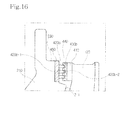
- FIGS. 14 to 16 are partially enlarged views of a centrifugal compressor shown in FIG. 13 .
- the description about the elements and structures that have been described in the first to third exemplary embodiments will be omitted in order to avoid redundancy.
- the centrifugal compressor according to the fourth embodiment of the present inventive concept includes a second sealing unit 400 having at least one fourth sealing protrusion 420b protruding toward the second partial shroud 410 from the inner surface 211 of the housing.
- the fourth sealing protrusion 420b includes a rear end 420b-1 fixed to the inner surface 211 and a front end 420b-2 spaced part from the second partial shroud 410 by a predetermined distance C.
- the sealing protrusion constituting the second sealing unit 400 protrudes toward the second partial shroud 410 from the inner surface 211 of the housing 200.
- the fourth sealing protrusion 420b may be integrally formed with the housing 200 as shown in FIG. 13 .
- the fourth sealing protrusion 420b may be attached to an inner surface of a second support member 450 having an annular shape and inserted into the inner surface 211 of the housing 200.
- the fourth sealing protrusion 420b may be separately prepared as an individual member.
- the rear end 420b-1 of the fourth sealing protrusion 420b may be attached to the inner surface of the second support member 450 through a welding scheme or may be integrally formed with the inner surface of the second support member 450.
- a fourth sealing pad 430b may be provided to prevent the wear and deformation of the sealing protrusion.
- the fourth sealing pad 430b may be formed on the outer surface of the second partial shroud 410.
- the fourth sealing pad 430b may be formed by using a material having low plastic deformation and predetermined elasticity as well as hardness lower than that of the second sealing protrusion.
- the fourth sealing pad 430b is formed with a fourth sealing groove 440 having a shape corresponding to a shape of the fourth sealing protrusion 420b.
- the front end 420b-2 of the fourth sealing protrusion 420b may be inserted into the fourth sealing groove 440.
- FIG. 17 is an axial cross-sectional view showing a centrifugal compressor according to a fifth exemplary embodiment of the present inventive concept.
- the centrifugal compressor according to the fifth exemplary embodiment includes a first sealing unit 300 adjacent to the inlet 220 of the housing 200 and a second sealing unit 400 adjacent to the outlet 230 of the housing 200.
- the centrifugal compressor according to the fifth embodiment of the present inventive concept includes the first sealing unit 300 according to the first embodiment and the second sealing unit 400 according to the third embodiment.
- the centrifugal compressor according to the fifth exemplary embodiment includes the first sealing unit 300 having a first partial shroud 310 and a first sealing protrusion 320a and the second sealing unit 400 having a second partial shroud 410 and a third sealing protrusion 420a.
- the fluid leakage can be effectively prevented at the inlet 220 and the outlet 230 of the housing 200, so that the efficiency of the impeller 100 can be upgraded to the level of the typical shroud impeller.
- the blades 120 adjacent to the inlet 220 of the housing 200 can be reinforced by the first partial shroud 310 and the blades adjacent to the outlet 230 of the housing 200 can be reinforced by the second partial shroud 410 so that the strength of the impeller 100 can be improved to the level of the typical shroud impeller.
- the technical features of the first sealing pad and the first sealing groove according to the first exemplary embodiment and the technical features of the third sealing pad and the third sealing groove according to the third exemplary embodiment can be adopted in the fifth exemplary embodiment illustrated in FIG. 17 .
- FIG. 18 is an axial cross-sectional view showing the centrifugal compressor according to a sixth exemplary embodiment of the present inventive concept.
- the centrifugal compressor includes a first sealing unit 300 adjacent to the inlet 220 of the housing 200 and a second sealing unit 400 adjacent to the outlet 230 of the housing 200.
- the first sealing unit 300 includes at least one second sealing protrusion 320b protruding toward the first partial shroud 310 from the inner surface 211 of the housing 200 and the second sealing unit 400 includes at least one fourth sealing protrusion 420b protruding toward the second partial shroud 410 from the inner surface 211 of the housing 200
- the centrifugal compressor according to the sixth exemplary embodiment includes the first sealing unit 300 according to the second exemplary embodiment and the second sealing unit 400 according to the fourth embodiment.
- the centrifugal compressor according to the sixth exemplary embodiment includes the first sealing unit 300 having the first partial shroud 310 and the second sealing protrusion 320b and the second sealing unit 400 having the second partial shroud 410 and the fourth sealing protrusion 420b.
- the technical features of the second sealing pad and the second sealing groove according to the second exemplary embodiment and the technical features of the fourth sealing pad and the fourth sealing groove according to the fourth exemplary embodiment can be adopted in the sixth embodiment illustrated in FIG. 18 .
- first sealing unit 300 according to the first exemplary embodiment and the second sealing unit 400 according to the fourth exemplary embodiment and the technical features of the first sealing unit 300 according to the second exemplary embodiment and the second sealing unit 400 according to the third exemplary embodiment can be adopted in the sixth exemplary embodiment without departing from the scope of the present inventive concept.
Landscapes
- Engineering & Computer Science (AREA)
- Mechanical Engineering (AREA)
- General Engineering & Computer Science (AREA)
- Structures Of Non-Positive Displacement Pumps (AREA)
Abstract
Description
- Aspects of the present inventive concept relate to a centrifugal compressor, and more particularly, to a centrifugal compressor capable of minimizing leakage of a fluid in the process of compressing the fluid and having high aerodynamic performance.
- In general, a centrifugal compressor signifies a device for compressing a fluid by converting kinetic energy into pressure energy through a centrifugal force by sucking the fluid in a rotational axis direction of a high-speed rotor or an impeller and circumferentially exhausting the fluid.
- The centrifugal compressor has been extensively applied to various industrial fields such as various types of air conditioning facilities and gas turbine systems.
- As shown in
FIG. 1A , a general centrifugal compressor includes animpeller 10 having arotary hub 11 connected to adriving shaft 40 and a plurality ofblades 12 radially provided about a rotational axis X-X' of therotary hub 11. - In addition, the centrifugal compressor includes a
housing 20 formed with an inlet into which a fluid to be compressed is introduced and an outlet through which the compressed fluid is discharged and provided with aninner surface 21 fixedly adjacent to theblades 12 and adiffuser 30 that reduces a dynamic pressure component of a voltage component increased due to force received from theimpeller 10 and increases a static pressure component thereof. - An impeller used for the general centrifugal compressor constructed as described above is classified into an open impeller and a shroud impeller according to the capacity and performance thereof.
- That is, as shown in
FIG. 11B , an impeller where outer ends of theblades 12 are open may be called anopen impeller 10 or an unshrouded impeller having no shrouds. - Since the outer ends of the
blades 12 are open in theopen impeller 10, mechanical processing is possible so that theopen impeller 10 can be easily manufactured. In addition, precise profile tolerance may be ensured so that a structure of theopen impeller 10 is stable and a manufacturing cost of theopen impeller 10 is relatively low. - However, since the outer ends of the blades are open in the
open impeller 10, some of a compressed fluid is leaked through a gap formed between an outer end of the blade and an inner surface of the housing so that flow loss occurs. In addition, the flow loss is significantly increased due to leakage in an inlet A and an outlet B of thehousing 20. - Meanwhile, asshowninFIGs. 2Aand2B, the
shroud impeller 10 includes ashroud 13 that connects outer ends of a plurality ofblades 12 provided in therotary hub 11 to each other while surrounding the outer ends of theblades 12. - In the
shroud impeller 10, a closed fluid path for a fluid to be compressed is formed byadjacent blades 12 and theshroud 13 so that flow loss may be reduced as compared with that of the open impeller, thereby representing higher compression efficiency. - Further, the
shroud 13 serves as a reinforcing structure connecting theblades 12 to each other so that theshroud impeller 10 has strength higher than that of the open impeller. - However, in order to form a path of a fluid to be compressed inside the shroud, the shroud impeller has a very complicated three-dimensional structure and thus processing is not easy and a manufacturing cost is considerably increased.
- As a related art of the shroud impeller,
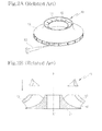
FIG. 2B shows a method of mechanically processing a monolithic rotor having a disc shape by acutting tool 50 controlled using a numerical control tool, which is disclosed inU.S. Patent No. 7,305,762 . However, the above patent may not be compatible with a complicated inner fluid path due to the structural problem, and there is a limitation in processing due to a shape of the cutting tool and the manufacturing cost is increased. - Further,
FIG. 2B shows a method of manufacturing an impeller by bonding an upstream impeller member and a downstream impeller member to each other after the upstream impeller member and the downstream impeller member are separately processed, which is disclosed in Japanese unexamined patent publication No.2010-121612 - However, an error may occur when bonding a plurality of members which are separately processed and it is difficult to maintain accurate shapes of a blade and a shroud.
- In addition, strength of a bonding part is so low that the above method is not suitable for a compressor of a gas turbine which is rotated at a high speed.
- In order to solve the above problem, as disclosed in
U.S. patent publication No. 2011-0318183 (hereinafter, referred to as patent document 1), a technology of forming an integral shroud in a blade, and forming a partially divided shroud, and bonding the blade to the integral shroud by brazing welding, stick welding, ultrasonic welding, or electron beam welding has been suggested. - In addition, Korean patent registration No.
10-0745507 - However, in the case of the
patent document 1, although strength may be improved by divided shrouds bonded to an integral shroud, processing of the divided shroud is complicated and a bonding work is significantly complicated and inconvenient. - Furthermore, if the divided shrouds are not precisely and accurately bonded and an error occurs, dangerous situation may be caused when the impeller is used for a gas turbine rotated at a high speed.
- In addition, in the case of the
patent document 2, since the partial shroud is formed at a region where compressed gas is exhausted, the problems occurring in the art may not be solved, that is, some of a compressed fluid is leaked through a gap formed between an outer end of the blade and an inner surface of the housing and thus flow loss occurs and the flow loss is significantly increased due to leakage in an inlet of the housing. - Exemplary embodiment have been made in an effort to solve the above-described problems, and an aspect of the present inventive concept provides a centrifugal compressor capable of minimizing leakage of a fluid in the process of compressing the fluid and having high aerodynamic performance by providing a sealing unit between an impeller and an inner surface of a housing.
- According to another aspect of the present inventive concept, there is provided a centrifugal compressor having higher strength as compared with an open impeller and superior workability as compared with a shroud impeller.
- According to an exemplary embodiment, there is provided a centrifugal compressor including an impeller including a plurality of blades radially disposed about a rotational axis; a housing formed with an inlet into which a fluid to be compressed by the impeller is introduced and an outlet through which a compressed fluid is discharged and having an inner surface adjacent to the blades; a sealing unit disposed adjacent to one of the inlet and the outlet and configured to seal between outer ends of the blades and the inner surface; and a partial shroud disposed adjacent to the sealing unit and formed at one of the inlet and the outlet and configured to partially surround outer peripheral portions of the outer ends of the blades.
- The sealing unit may include a first sealing unit disposed adjacent to the inlet and the first sealing unit includes a first partial shroud disposed adjacent to the inlet and configured to partially surround the outer peripheral portions of the outer ends of the blades.
- The first sealing unit may include at least one first sealing protrusion protruding toward the inner surface from the first partial shroud, a rear end of the first sealing protrusion is fixed to the first partial shroud, and a front end of the first sealing protrusion is spaced apart from the inner surface by a predetermined interval.
- The first sealing protrusion may be integrally formed with the first partial shroud.
- The centrifugal compressor may further include a first sealing pad on the inner surface adjacent to the first sealing protrusion, wherein the first sealing pad may include a material having hardness lower than hardness of the first sealing protrusion.
- The first sealing pad may be formed with a first sealing groove having a shape corresponding to a shape of the first sealing protrusion, and a front end of the first sealing protrusion is inserted into the first sealing groove.
- The first sealing unit may include a second sealing protrusion protruding toward the first partial shroud from the inner surface, a rear end of the second sealing protrusion is fixed to the inner surface, and a front end of the second sealing protrusion is spaced apart from the first partial shroud by a predetermined interval.
- The second sealing protrusion may be integrally formed with the housing.
- The first sealing unit may further include a first support member having one surface attached to the inner surface and an opposite surface formed with the second sealing protrusion.
- The second sealing protrusion may be integrally formed with the first support member.
- The centrifugal compressor may further include a second sealing pad on an outer surface of the first partial shroud adjacent to the second sealing protrusion, wherein the second sealing pad may include a material having hardness lower than hardness of the second sealing protrusion.
- The second sealing pad may be formed with a second sealing groove having a shape corresponding to a shape of the second sealing protrusion, and a front end of the second sealing protrusion is inserted into the second sealing groove.
- The sealing unit may include a second sealing unit disposed adjacent to the outlet and the second sealing unit includes a second partial shroud disposed adjacent to the outlet to partially surround the outer peripheral portions of the outer ends of the blades.
- The second sealing unit may further include a third sealing protrusion protruding toward the inner surface from the second partial shroud, a rear end of the third sealing protrusion is fixed to the second partial shroud, and a front end of the third sealing protrusion is spaced apart from the inner surface by a predetermined interval.
- The third sealing protrusion may be integrally formed with the second partial shroud.
- The centrifugal compressor may further include a third sealing pad on the inner surface adjacent to the third sealing protrusion, wherein the third sealing pad may include a material having hardness lower than hardness of the third sealing protrusion.
- The third sealing pad may be formed with a third sealing groove having a shape corresponding to a shape of the third sealing protrusion, and a front end of the third sealing protrusion is inserted into the third sealing groove.
- The second sealing unit may further include a fourth sealing protrusion protruding toward the second partial shroud from the inner surface, a rear end of the fourth sealing protrusion is fixed to the inner surface, and a front end of the fourth sealing protrusion is spaced apart from the second partial shroud by a predetermined interval.
- The fourth sealing protrusion may be integrally formed with the housing.
- The second sealing unit may further include a second support member having one surface attached to the inner surface and an opposite surface formed with the fourth sealing protrusion.
- The fourth sealing protrusion may be integrally formed with the second support member.
- The centrifugal compressor may further include a fourth sealing pad on an outer surface of the second partial shroud adjacent to the fourth sealing protrusion, wherein the fourth sealing pad may include a material having hardness lower than hardness of the fourth sealing protrusion.
- The fourth sealing pad may be formed with a fourth sealing groove having a shape corresponding to a shape of the fourth sealing protrusion, and a front end of the fourth sealing protrusion is inserted into the fourth sealing groove.
- The sealing unit may include a first sealing unit disposed adjacent to the inlet and a second sealing unit disposed adjacent to the outlet, the first sealing unit may include a first partial shroud disposed adjacent to the inlet to partially surround the outer peripheral portions of the outer ends of the blades, and the second sealing unit may include a second partial shroud disposed adjacent to the outlet to partially surround the outer peripheral portions of the outer ends of the blades.
- The first sealing unit may include a first sealing protrusion protruding toward the inner surface from the first partial shroud, and the second sealing unit may include a third sealing protrusion protruding toward the inner surface from the second partial shroud.
- A rear end of the first sealing protrusion may be fixed to the first partial shroud, a front end of the first sealing protrusion may be spaced apart from the inner surface by a predetermined interval, a rear end of the third sealing protrusion may be fixed to the second partial shroud, and a front end of the third sealing protrusion may be spaced apart from the inner surface by a predetermined interval.
- The first sealing unit may include a second sealing protrusion protruding toward the first partial shroud from the inner surface, and the second sealing unit may include a fourth sealing protrusion protruding toward the second partial shroud from the inner surface.
- A rear end of the second sealing protrusion may be fixed to the inner surface, a front end of the first sealing protrusion may be spaced apart from the first partial shroud by a predetermined interval, a rear end of the fourth sealing protrusion may be fixed to the inner surface, and a front end of the fourth sealing protrusion may be spaced apart from the second partial shroud by a predetermined interval.
- The centrifugal compressor according to the present inventive concept includes the sealing unit to seal the gap formed between the impeller and the inner surface of the housing, so the leakage of fluid to be compressed can be prevented at the fluid inlet and the fluid outlet, thereby maximizing the compression efficiency.
- In addition, the partial shroud is provided at a portion of the impeller adjacent to the fluid inlet or the fluid outlet, so the centrifugal compressor may have higher strength suitable for high-speed rotation as compared with the open impeller and may have superior workability as compared with the shroud impeller. In addition, the centrifugal compressor according to the present inventive concept may have the precise profile tolerance and can be manufactured at a lower cost while ensuring the structural stability.
-
-
FIGs. 1A and 1B show a sectional view illustrating a centrifugal compressor including an open impeller and a perspective view illustrating the open impeller according to the related art; -
FIGs. 2A and 2B show a perspective view and a sectional view illustrating a method of processing a shroud impeller according to the related art, respectively; -
FIG. 3 is an axial cross-sectional view showing a centrifugal compressor according to a first embodiment of the present inventive concept; -
FIGS. 4 and5 are partially enlarged views of a centrifugal compressor shown inFIG. 3 ; -
FIG. 6 is an axial cross-sectional view showing a centrifugal compressor according to a second exemplary embodiment of the present inventive concept; -
FIGS. 7 to 9 are partially enlarged views of a centrifugal compressor shown inFIG. 6 ; -
FIG. 10 is an axial cross-sectional view showing a centrifugal compressor according to a third exemplary embodiment of the present inventive concept; -
FIGS. 11 and12 are partially enlarged views of a centrifugal compressor shown inFIG. 10 ; -
FIG. 13 is an axial cross-sectional view showing a centrifugal compressor according to a fourth exemplary embodiment of the present inventive concept; -
FIGS. 14 to 16 are partially enlarged views of a centrifugal compressor shown inFIG. 13 ; -
FIG. 17 is an axial cross-sectional view showing a centrifugal compressor according to a fifth exemplary embodiment of the present inventive concept; and -
FIG. 18 is an axial cross-sectional view showing a centrifugal compressor according to a sixth exemplary embodiment of the present inventive concept. - Hereinafter, exemplary embodiments of the present inventive concept will be described in detail with reference to the accompanying drawings, but the present inventive concept will not be limited to the following embodiments.
-
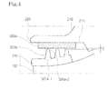
FIG. 3 is an axial cross-sectional view showing a centrifugal compressor according to a first exemplary embodiment of the present inventive concept andFIGS. 4 and5 are partially enlarged views of the centrifugal compressor shown inFIG. 3 . - As shown in the drawings, the centrifugal compressor according the first exemplary embodiment includes an
impeller 100 and ahousing 200. Theimpeller 100 includes arotary hub 110 rotating about a rotational axis X-X' by receiving power from a driving shaft (not shown) and a plurality ofblades 120 radially provided on therotary hub 110 about the rotational axis X-X'. Thehousing 200 receives theimpeller 100 therein and is formed with aninner surface 211 adjacent to theblades 120. - The
rotary hub 110 is connected to the driving shaft (not shown) and receives rotating force from the driving shaft. Therotary hub 110 may be made from a material having predetermined strength suitable for high speed. In addition, therotary hub 110 may be fabricated by heat-treating chromium-molybdenum steel, nickel chromium-molybdenum steel, or stainless steel. - Further, the
rotary hub 110 may have a conical shape having a sectional area gradually reduced in the direction of the rotational axis X-X'. In this case, a front center portion of the conical shape in the direction of the rotational axis X-X' becomes aninlet 220 of a fluid, and a rear peripheral portion of the conical shape in the radial direction becomes an outlet of the fluid. Although an inclined surface of a peripheral side in the conical shape of the rotary hub is illustrated as a curve surface having a predetermined curvature inFIG. 3 , the present inventive concept is not limited thereto. - The
blades 120 are radially disposed on the inclined surface of therotary hub 110 while being spaced apart from each other by a predetermined interval. Theblades 120 may have a three-dimensional curved shape by taking specifications of a compressor, such as application purpose, compression capacity and flow velocity, into consideration. Theblades 120 may be integrally formed with therotary hub 110. It is also possible to bond the blade to therotary hub 110 through a welding scheme after processing the blade by using a material the same as that of therotary hub 110. - In addition, the welding scheme may not provide sufficient strength required for the high-
speed impeller 100. However, as will be described later, since the strength of theimpeller 100 according to the present inventive concept can be reinforced by a firstpartial shroud 310 or a second partial, theimpeller 100 may have the condition applicable for the high-rotation compressor. - The
housing 200 has an internal space for receiving theimpeller 100 and is configured to serve as a stator to rotatably support theimpeller 100. - Further, the
housing 200 includes acover member 210, which forms theinlet 220 of a fluid to be compressed and theoutlet 230 of the compressed fluid and has aninner surface 211 adjacent to theblades 120. - Meanwhile, the centrifugal compressor according to the first exemplary embodiment includes a
first sealing unit 300 disposed adjacent to theinlet 220 to seal a gap formed between outer ends of theblades 120 and theinner surface 211. - In detail, as described above, the centrifugal compressor according to the first exemplary embodiment includes the
first sealing unit 300 to prevent the leakage of fluid to be compressed at theinlet 220. - The
first sealing unit 300 is a non-contact type sealing unit, for instance, a labyrinth sealing unit. In order to implement the labyrinth sealing unit, there is provided a firstpartial shroud 310 having an annular shape and disposed adjacent to the inlet to partially surround the outer ends of theblades 120 and at least onefirst sealing protrusion 320a protruding toward theinner surface 211 from the firstpartial shroud 310. - The first
partial shroud 310 has a cylindrical shape configured to partially surround outer ends of theblades 120 adjacent to theinlet 220. The firstpartial shroud 310 may be integrally formed with theblades 120 or may be fabricated separately from theblades 120 and bonded to the outer ends of theblades 120 through a welding scheme. - As described above, since the first
partial shroud 310 partially surrounds the outer ends of theblades 120 adjacent to theinlet 220, the fluid introduced into theinlet 220 can be prevented from being leaked through a gap between theblades 120 and theinner surface 211 of thehousing 200. - In addition, since the outer ends of the
blades 120 adjacent to theinlet 220 can be securely fixed by the firstpartial shroud 310, the centrifugal compressor may have higher strength as compared with theopen impeller 100 and may have the simple structure. - The
first sealing unit 320a seals a gap formed between the firstpartial shroud 310 and theinner surface 211 through the labyrinth sealing scheme. That is, thefirst sealing unit 320a may allow a flow f1 of the fluid that has passed through theinlet 220 of thehousing 200 to be introduced toward theblades 120 of theimpeller 100 and prevent the fluid introduced into theblades 120 from flowing back to theinlet 220 through the gap formed between theblades 120 and theinner surface 211, so that the compression efficiency can be improved approximate to the compression efficiency of the shroud impeller. - The sealing
protrusion 320a has arear end 320a-1 fixed to the firstpartial shroud 310 and afront end 320a-2 protruding toward theinner surface 211 so that a predetermined gap is formed between thefront end 320a-2 and the inner surface 211 (see, C inFIG. 4 ). - The
first sealing protrusion 320a may be separately fabricated as an individual member and therear end 320a-1 of thefirst sealing protrusion 320a may be bonded to the firstpartial shroud 310 through the welding scheme, or thefirst sealing protrusion 320a may be integrally formed with the firstpartial shroud 310. In this case, the firstpartial shroud 310 may serve as a support member for thefirst sealing protrusion 320a. - As described above, the
first sealing protrusion 320a prevents the fluid from flowing rearward or forward in the axial direction and it is preferable to provide a plurality of first sealingprotrusions 320a as shown inFIG. 3 . - The number of the first sealing protrusion is not limited, but may be variously adjusted by taking specifications of a compressor, such as application purpose, compression capacity and flow velocity, into consideration.
- In the first embodiment shown in
FIG. 3 , thefirst sealing protrusion 320a may serve as a rotator and theinner surface 211 of thehousing 200 may serve as a stator in labyrinth sealing. - Meanwhile, as shown in
FIG. 4 , the centrifugal compressor according to the first exemplary embodiment may further include afirst sealing pad 330a having an annular shape. Thefirst sealing pad 330a has hardness lower than thefirst sealing protrusion 320a and is provided on theinner surface 211 in opposition to thefirst sealing protrusion 320a. - In other words, since the
first sealing unit 300 adopts the labyrinth sealing scheme, thefirst sealing protrusion 320a serves as the rotator and theinner surface 211 of thehousing 200 serves as the stator so that vibration may occurs in the direction perpendicular to the rotating axis due to the rotation of theimpeller 100 when the centrifugal compressor is operated. As a result, thefirst sealing protrusion 320a serving as the rotator may interfere with theinner surface 211 serving as the stator, and thus theinner surface 211 may be worn or thefirst sealing protrusion 320a may be deformed. - If the wear or deformation occurs, the gap for maintaining the labyrinth sealing may be excessively enlarged, thereby deteriorating the sealing performance.
- For this reason, the exemplary embodiment provides the
first sealing pad 330a to prevent the wear or deformation. In order to prevent the wear of theinner surface 211, thefirst sealing pad 330a is formed on theinner surface 211 of thehousing 200 corresponding to thefirst sealing protrusion 320a by using a material having low plastic deformation and predetermined elasticity, such as a resin, a coating, a honeycomb or a light-weight material. - In addition, in order to prevent the deformation of the
first sealing protrusion 320a, thefirst sealing pad 330a may be fabricated by using a material having hardness lower than that of thefirst sealing protrusion 320a. - Since the
first sealing pad 330a is fabricated by using the material described above, the predetermined gap C can be ensured between thefront end 320a-2 of thefirst sealing protrusion 320a and thefirst sealing pad 330a so that the high sealing performance can be achieved. - Meanwhile, as shown in
FIG. 5 , thesealing pad 330a of the centrifugal compressor according to the first exemplary embodiment is formed with afirst sealing groove 340 having a shape corresponding to a shape of thefirst sealing protrusion 320a and thefront end 320a-2 of thefirst sealing protrusion 320a may be fitted into thefirst sealing groove 340. - In addition, a diameter of the
impeller 110 rotating at a high speed during the operation of the centrifugal compressor may be enlarged due to centrifugal force and heat and thefirst sealing protrusion 320a may penetrate into thefirst sealing pad 330a. For this reason, thefirst sealing pad 330a may be made from a material having hardness lower than that of thefirst sealing protrusion 320a. The sealing protrusion and sealing pad according to other embodiments of the present inventive concept also may have the above feature. - In this manner, since the
first sealing groove 340, into which thefront end 320a-2 of thefirst sealing protrusion 320a is partially inserted, is formed in thefirst sealing pad 330a, a sealing area between thefront end 320a-2 of thefirst sealing protrusion 320a and thefirst sealing pad 330a can be increased, so that the sealing efficiency can be improved. In addition, the wear and deformation caused by the vibration of theimpeller 100 can be diminished and the higher sealing performance can be ensured. -
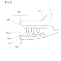
FIG. 6 is an axial cross-sectional view showing a centrifugal compressor according to a second exemplary embodiment of the present inventive concept, andFIGS. 7 to 9 are partially enlarged views of the centrifugal compressor shown inFIG. 6 . In the following description of the second exemplary embodiment, the description about the elements and structures that have been described in the first exemplary embodiment will be omitted in order to avoid redundancy. - As shown in the drawings, the centrifugal compressor according to the second exemplary embodiment includes at least one
second sealing protrusion 320b protruding toward the firstpartial shroud 310 from theinner surface 211 of thehousing 200. Thesecond sealing protrusion 320b includes arear end 320b-1 fixed to theinner surface 211 and afront end 320b-2 spaced apart from the firstpartial shroud 310 by a predetermined distance C. - That is, different from the first exemplary embodiment, the sealing protrusion constituting the
first sealing unit 300 protrudes toward the firstpartial shroud 310 from theinner surface 211 of thehousing 200. - As shown in
FIG. 6 , thesecond sealing protrusion 320b may be integrally formed with thehousing 200. In addition, as shown inFIG. 7 , thesecond sealing protrusion 320b may be attached to an inner surface of afirst support member 350 having an annular shape and inserted into theinner surface 211 of thehousing 200. Further, thesecond sealing protrusion 320b may be separately prepared as an individual member such that therear end 320b-1 of thesecond sealing protrusion 320b can be attached to the inner surface of thefirst support member 350 through a welding scheme or thesecond sealing protrusion 320b may be integrally formed with the inner surface of thefirst support member 350. - In this manner, since the
second sealing protrusion 320b is provided at theinner surface 211 of thehousing 200, other than the firstpartial shroud 310, the manufacturing cost for the firstpartial shroud 310 and theimpeller 100, which are relatively expensive and complicate in shapes, can be reduced. - Meanwhile, according to the second exemplary embodiment, the
second sealing protrusion 320b serves as a stator and the firstpartial shroud 310 may serve as a rotator. - Therefore, as shown in
FIG. 8 , asecond sealing pad 330b can be formed on an outer surface of the firstpartial shroud 310 to prevent the sealing protrusion from being worn and deformed. Thesecond sealing pad 330b is also formed by using a material having low plastic deformation and predetermined elasticity as well as hardness lower than that of thesecond sealing protrusion 320b. - In addition, similar to the first exemplary embodiment, the
second sealing pad 330b is formed with asecond sealing groove 340 having a shape corresponding to a shape of thesecond sealing protrusion 320b as shown inFIG. 9 . Thefront end 320b-2 of thesecond sealing protrusion 320b may be inserted into thesecond sealing groove 340. -
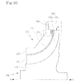
FIG. 10 is an axial cross-sectional view showing a centrifugal compressor according to a third exemplary embodiment of the present inventive concept andFIGS. 11 and12 are partially enlarged views of the centrifugal compressor shown inFIG. 10 . In the following description of the third exemplary embodiment, the description about the elements and structures that have been described in the first and second exemplary embodiments will be omitted in order to avoid redundancy. - As shown in the drawings, the centrifugal compressor according to the third exemplary embodiment includes a
second sealing unit 400 adjacent to theoutlet 230 of thehousing 200. - In detail, the centrifugal compressor according to the third exemplary embodiment includes the
second sealing unit 400 to prevent the leakage of the fluid flow f2 at theoutlet 230 of the compressed fluid. - The
second sealing unit 400 includes a secondpartial shroud 410 having an annular shape and disposed adjacent to theoutlet 230 to partially surround the outer ends of theblades 120 and at least onethird sealing protrusion 420a protruding toward theinner surface 211 from the secondpartial shroud 410. - Similar to the first exemplary embodiment described above, a
rear end 420a-1 of thethird sealing protrusion 420a is fixed to the secondpartial shroud 410 and afront end 420a-2 of thethird sealing protrusion 420a is spaced apart from theinner surface 211 by a predetermined distance (see C ofFIG. 11 ) such that thethird sealing protrusion 420a serves as a rotator and theinner surface 211 of thehousing 200 serves as a stator, thereby implementing the labyrinth sealing. - The second
partial shroud 410 has a hollow disc shape corresponding to a shape of theblades 120 adjacent to theoutlet 230 of the fluid. The secondpartial shroud 410 partially surrounds the outer ends of theblades 120 to serve as a support member for thethird sealing protrusion 420a. Thus, the outer ends of the blades adjacent to theoutlet 230 of the fluid can be securely fixed by the secondpartial shroud 410, thereby implementing a high-strength structure. - Similar to the first partial shroud, the second
partial shroud 410 may be integrally formed with theblades 120 or may be separately prepared and attached to the outer ends of theblades 120 through a welding scheme. - Meanwhile, similar to the first exemplary embodiment, the
third sealing protrusion 420a may be prepared as an individual member. In this case, therear end 420a-1 of thethird sealing protrusion 420a may be attached to the secondpartial shroud 410 through a welding scheme or may be integrally formed with the first partial shroud. - In addition, as shown in
FIG. 11 , the centrifugal compressor according to the third exemplary embodiment may further include athird sealing pad 430a provided at theinner surface 211 in opposition to thethird sealing protrusion 420a and having an annular shape. Thethird sealing pad 420a may have hardness lower than that of thethird sealing protrusion 420a and may be formed by using a material having low plastic deformation and predetermined elasticity. - Further, as shown in
FIG. 12 , thethird sealing pad 430a is formed with athird sealing groove 440 having a shape corresponding to a shape of thethird sealing protrusion 420a. Thefront end 420a-2 of thethird sealing protrusion 420a may be inserted into thethird sealing groove 440. -
FIG. 13 is an axial cross-sectional view showing a centrifugal compressor according to a fourth exemplary embodiment of the present inventive concept, andFIGS. 14 to 16 are partially enlarged views of a centrifugal compressor shown inFIG. 13 . In the following description of the fourth exemplary embodiment, the description about the elements and structures that have been described in the first to third exemplary embodiments will be omitted in order to avoid redundancy. - As shown in the drawings, the centrifugal compressor according to the fourth embodiment of the present inventive concept includes a
second sealing unit 400 having at least onefourth sealing protrusion 420b protruding toward the secondpartial shroud 410 from theinner surface 211 of the housing. Thefourth sealing protrusion 420b includes arear end 420b-1 fixed to theinner surface 211 and afront end 420b-2 spaced part from the secondpartial shroud 410 by a predetermined distance C. - In detail, different from the third exemplary embodiment, according to the fourth exemplary embodiment, the sealing protrusion constituting the
second sealing unit 400 protrudes toward the secondpartial shroud 410 from theinner surface 211 of thehousing 200. - That is, similar to the second exemplary embodiment, the
fourth sealing protrusion 420b may be integrally formed with thehousing 200 as shown inFIG. 13 . In addition, as shown inFIG. 14 , thefourth sealing protrusion 420b may be attached to an inner surface of asecond support member 450 having an annular shape and inserted into theinner surface 211 of thehousing 200. - Further, the
fourth sealing protrusion 420b may be separately prepared as an individual member. In this case, therear end 420b-1 of thefourth sealing protrusion 420b may be attached to the inner surface of thesecond support member 450 through a welding scheme or may be integrally formed with the inner surface of thesecond support member 450. - In addition, similar to the second exemplary embodiment, a
fourth sealing pad 430b may be provided to prevent the wear and deformation of the sealing protrusion. As shown inFIG. 15 , thefourth sealing pad 430b may be formed on the outer surface of the secondpartial shroud 410. Thefourth sealing pad 430b may be formed by using a material having low plastic deformation and predetermined elasticity as well as hardness lower than that of the second sealing protrusion. - Further, as shown in
FIG. 16 , thefourth sealing pad 430b is formed with afourth sealing groove 440 having a shape corresponding to a shape of thefourth sealing protrusion 420b. Thefront end 420b-2 of thefourth sealing protrusion 420b may be inserted into thefourth sealing groove 440. -
FIG. 17 is an axial cross-sectional view showing a centrifugal compressor according to a fifth exemplary embodiment of the present inventive concept. - As shown in
FIG. 17 , the centrifugal compressor according to the fifth exemplary embodiment includes afirst sealing unit 300 adjacent to theinlet 220 of thehousing 200 and asecond sealing unit 400 adjacent to theoutlet 230 of thehousing 200. - In detail, the centrifugal compressor according to the fifth embodiment of the present inventive concept includes the
first sealing unit 300 according to the first embodiment and thesecond sealing unit 400 according to the third embodiment. In more detail, the centrifugal compressor according to the fifth exemplary embodiment includes thefirst sealing unit 300 having a firstpartial shroud 310 and afirst sealing protrusion 320a and thesecond sealing unit 400 having a secondpartial shroud 410 and athird sealing protrusion 420a. - Since both of the first and
second units inlet 220 and theoutlet 230 of thehousing 200, so that the efficiency of theimpeller 100 can be upgraded to the level of the typical shroud impeller. - Further, the
blades 120 adjacent to theinlet 220 of thehousing 200 can be reinforced by the firstpartial shroud 310 and the blades adjacent to theoutlet 230 of thehousing 200 can be reinforced by the secondpartial shroud 410 so that the strength of theimpeller 100 can be improved to the level of the typical shroud impeller. - In addition, although not shown in the drawing, the technical features of the first sealing pad and the first sealing groove according to the first exemplary embodiment and the technical features of the third sealing pad and the third sealing groove according to the third exemplary embodiment can be adopted in the fifth exemplary embodiment illustrated in
FIG. 17 . -
FIG. 18 is an axial cross-sectional view showing the centrifugal compressor according to a sixth exemplary embodiment of the present inventive concept. - As shown in
FIG. 18 , the centrifugal compressor according to the sixth exemplary embodiment includes afirst sealing unit 300 adjacent to theinlet 220 of thehousing 200 and asecond sealing unit 400 adjacent to theoutlet 230 of thehousing 200. Thefirst sealing unit 300 includes at least onesecond sealing protrusion 320b protruding toward the firstpartial shroud 310 from theinner surface 211 of thehousing 200 and thesecond sealing unit 400 includes at least onefourth sealing protrusion 420b protruding toward the secondpartial shroud 410 from theinner surface 211 of thehousing 200 - In detail, the centrifugal compressor according to the sixth exemplary embodiment includes the
first sealing unit 300 according to the second exemplary embodiment and thesecond sealing unit 400 according to the fourth embodiment. In more detail, the centrifugal compressor according to the sixth exemplary embodiment includes thefirst sealing unit 300 having the firstpartial shroud 310 and thesecond sealing protrusion 320b and thesecond sealing unit 400 having the secondpartial shroud 410 and thefourth sealing protrusion 420b. - Although not shown in the drawing, the technical features of the second sealing pad and the second sealing groove according to the second exemplary embodiment and the technical features of the fourth sealing pad and the fourth sealing groove according to the fourth exemplary embodiment can be adopted in the sixth embodiment illustrated in
FIG. 18 . - In addition, although not shown in the drawing, the technical features of the
first sealing unit 300 according to the first exemplary embodiment and thesecond sealing unit 400 according to the fourth exemplary embodiment and the technical features of thefirst sealing unit 300 according to the second exemplary embodiment and thesecond sealing unit 400 according to the third exemplary embodiment can be adopted in the sixth exemplary embodiment without departing from the scope of the present inventive concept. - Although various examples have been illustrated and described, the present disclosure is not limited to the above-mentioned examples and various modifications can be made by those skilled in the art without departing from the scope of the appended claims. In addition, these modified examples should not be appreciated separately from technical spirits or prospects.
Claims (18)
- A centrifugal compressor comprising:an impeller comprising a plurality of blades radially disposed about a rotational axis;a housing comprising an inlet into which a fluid to be compressed by the impeller is introduced, an outlet through which the compressed fluid is discharged, and an inner surface adjacent to the plurality of blades;a sealing unit disposed adjacent to one of the inlet and the outlet to seal a space between outer ends of the plurality of blades and the inner surface; anda partial shroud disposed adjacent to the sealing unit and disposed at one of the inlet and the outlet to partially surround outer peripheral portions of the outer ends of the plurality of blades.
- The centrifugal compressor of claim 1, wherein the sealing unit comprises a first sealing unit disposed adjacent to the inlet and the first sealing unit comprises a first partial shroud disposed adjacent to the inlet to partially surround the outer peripheral portions of the outer ends of the plurality of blades.
- The centrifugal compressor of claim 2, wherein the first sealing unit comprises at least one first sealing protrusion protruding toward the inner surface from the first partial shroud, a rear end of the first sealing protrusion is fixed to the first partial shroud, and a front end of the first sealing protrusion is spaced apart from the inner surface by a predetermined interval.
- The centrifugal compressor of claim 3, further comprising a first sealing pad on the inner surface adjacent to the first sealing protrusion, wherein the first sealing pad comprises a material having a hardness lower than a hardness of the first sealing protrusion.
- The centrifugal compressor of claim 4, wherein the first sealing pad comprises a first sealing groove comprising a shape corresponding to a shape of the first sealing protrusion, and a front end of the first sealing protrusion is inserted into the first sealing groove.
- The centrifugal compressor of claim 2, wherein the first sealing unit comprises a second sealing protrusion protruding toward the first partial shroud from the inner surface, a rear end of the second sealing protrusion is fixed to the inner surface, and a front end of the second sealing protrusion is spaced apart from the first partial shroud by a predetermined interval.
- The centrifugal compressor of claim 6, wherein the first sealing unit further comprises a first support member comprising one surface attached to the inner surface and an opposite surface formed with the second sealing protrusion.
- The centrifugal compressor of claim 6, further comprising a second sealing pad on an outer surface of the first partial shroud adjacent to the second sealing protrusion, wherein the second sealing pad comprises a material having a hardness lower than a hardness of the second sealing protrusion.
- The centrifugal compressor of claim 8, wherein the second sealing pad comprises a second sealing groove comprising a shape corresponding to a shape of the second sealing protrusion, and a front end of the second sealing protrusion is inserted into the second sealing groove.
- The centrifugal compressor of claim 1, wherein the sealing unit comprises a second sealing unit disposed adjacent to the outlet and the second sealing unit comprises a second partial shroud disposed adjacent to the outlet to partially surround the outer peripheral portions of the outer ends of the plurality of blades.
- The centrifugal compressor of claim 10, wherein the second sealing unit further comprises a third sealing protrusion protruding toward the inner surface from the second partial shroud, a rear end of the third sealing protrusion is fixed to the second partial shroud, and a front end of the third sealing protrusion is spaced apart from the inner surface by a predetermined interval.
- The centrifugal compressor of claim 11, further comprising a third sealing pad on the inner surface adjacent to the third sealing protrusion, wherein the third sealing pad comprises a material having a hardness lower than a hardness of the third sealing protrusion.
- The centrifugal compressor of claim 12, wherein the third sealing pad comprises a third sealing groove comprising a shape corresponding to a shape of the third sealing protrusion, and a front end of the third sealing protrusion is inserted into the third sealing groove.
- The centrifugal compressor of claim 10, wherein the second sealing unit further comprises a fourth sealing protrusion protruding toward the second partial shroud from the inner surface, a rear end of the fourth sealing protrusion is fixed to the inner surface, and a front end of the fourth sealing protrusion is spaced apart from the second partial shroud by a predetermined interval.
- The centrifugal compressor of claim 14, wherein the second sealing unit further comprises a second support member comprising one surface attached to the inner surface and an opposite surface formed with the fourth sealing protrusion.
- The centrifugal compressor of claim 14, further comprising a fourth sealing pad on an outer surface of the second partial shroud adjacent to the fourth sealing protrusion, wherein the fourth sealing pad comprises a material having a hardness lower than a hardness of the fourth sealing protrusion.
- The centrifugal compressor of claim 16, wherein the fourth sealing pad is formed with a fourth sealing groove comprising a shape corresponding to a shape of the fourth sealing protrusion, and a front end of the fourth sealing protrusion is inserted into the fourth sealing groove.
- The centrifugal compressor of claim 1, wherein the sealing unit comprises a first sealing unit disposed adjacent to the inlet and a second sealing unit disposed adjacent to the outlet, the first sealing unit comprising a first partial shroud disposed adjacent to the inlet to partially surround the outer peripheral portions of the outer ends of the plurality of blades, and the second sealing unit comprising a second partial shroud disposed adjacent to the outlet to partially surround the outer peripheral portions of the outer ends of the plurality of blades.
Applications Claiming Priority (1)
| Application Number | Priority Date | Filing Date | Title |
|---|---|---|---|
| KR1020130031410A KR101501477B1 (en) | 2013-03-25 | 2013-03-25 | Centrifugal Compressor |
Publications (3)
| Publication Number | Publication Date |
|---|---|
| EP2784327A2 true EP2784327A2 (en) | 2014-10-01 |
| EP2784327A3 EP2784327A3 (en) | 2015-04-22 |
| EP2784327B1 EP2784327B1 (en) | 2018-05-16 |
Family
ID=48703212
Family Applications (1)
| Application Number | Title | Priority Date | Filing Date |
|---|---|---|---|
| EP13174085.4A Active EP2784327B1 (en) | 2013-03-25 | 2013-06-27 | Centrifugal compressor |
Country Status (3)
| Country | Link |
|---|---|
| US (2) | US20140286761A1 (en) |
| EP (1) | EP2784327B1 (en) |
| KR (1) | KR101501477B1 (en) |
Cited By (2)
| Publication number | Priority date | Publication date | Assignee | Title |
|---|---|---|---|---|
| FR3060672A1 (en) * | 2016-12-21 | 2018-06-22 | Valeo Systemes De Controle Moteur | ELECTRICAL COMPRESSOR WITH IMPROVED WHEEL |
| NL2024911B1 (en) * | 2020-02-14 | 2021-09-15 | Mi Partners B V | Device with contactless heat transfer |
Families Citing this family (21)
| Publication number | Priority date | Publication date | Assignee | Title |
|---|---|---|---|---|
| JP2016148308A (en) * | 2015-02-13 | 2016-08-18 | 三菱重工業株式会社 | Centrifugal compressor and geared centrifugal compressor |
| KR102556732B1 (en) * | 2015-05-15 | 2023-07-17 | 누보 피그노네 테크놀로지 에스알엘 | A centrifugal compressor impeller and a compressor including the impeller |
| DE102016001484A1 (en) * | 2016-02-11 | 2017-08-17 | Ebm-Papst St. Georgen Gmbh & Co. Kg | fan unit |
| US10227879B2 (en) * | 2016-02-11 | 2019-03-12 | General Electric Company | Centrifugal compressor assembly for use in a turbine engine and method of assembly |
| JP6419748B2 (en) * | 2016-04-05 | 2018-11-07 | ミネベアミツミ株式会社 | Centrifugal fan |
| IT201600106889A1 (en) * | 2016-10-24 | 2018-04-24 | Nuovo Pignone Tecnologie Srl | Diaphragm for centrifugal compressor |
| KR102347638B1 (en) * | 2017-08-08 | 2022-01-05 | 한화파워시스템 주식회사 | Semi-shrouded impeller |
| DE102017007860A1 (en) * | 2017-08-23 | 2019-02-28 | Wilo Se | Sealing at the suction mouth of a pump impeller |
| KR101876161B1 (en) * | 2018-04-04 | 2018-07-06 | 서울대학교산학협력단 | Leakage Flow Reduced Centrifugal Pump |
| KR102172654B1 (en) * | 2018-11-27 | 2020-11-02 | 한국가스공사 | Wear ring assembly of impeller for nlg pump |
| US11598347B2 (en) * | 2019-06-28 | 2023-03-07 | Trane International Inc. | Impeller with external blades |
| CN111043309B (en) * | 2019-12-18 | 2025-07-18 | 珠海格力电器股份有限公司 | Sealing structure with multiple sealing effects and water chilling unit |
| KR102782036B1 (en) * | 2020-11-13 | 2025-03-14 | 엘지전자 주식회사 | Compressor and Chiller including the same |
| KR20220065922A (en) * | 2020-11-13 | 2022-05-23 | 엘지전자 주식회사 | Compressor and Chiller including the same |
| CN112324703A (en) * | 2020-11-20 | 2021-02-05 | 珠海格力电器股份有限公司 | Sealing structure and compressor |
| KR102642363B1 (en) * | 2021-07-23 | 2024-03-04 | 엘지전자 주식회사 | Turbo compressor |
| CN113864211A (en) * | 2021-08-19 | 2021-12-31 | 青岛海尔智能技术研发有限公司 | Magnetic suspension pump, refrigeration equipment with same and air conditioner outdoor unit |
| US11486498B1 (en) * | 2021-09-10 | 2022-11-01 | Hamilton Sundstrand Corporation | Dynamic sealing labyrinth seals |
| CN118008859B (en) * | 2024-04-10 | 2024-06-25 | 浙江金盾风机股份有限公司 | Nuclear-grade emergency exhaust fan with low vibration and low leakage |
| GB2644074A (en) * | 2024-09-13 | 2026-03-18 | Rheenergise Ltd | A sealing arrangement for a turbine |
| US12595800B1 (en) * | 2024-11-29 | 2026-04-07 | Hyundai Motor Company | Low noise blower |
Citations (4)
| Publication number | Priority date | Publication date | Assignee | Title |
|---|---|---|---|---|
| KR100745507B1 (en) | 2001-08-21 | 2007-08-02 | 삼성테크윈 주식회사 | Turbo compressor |
| US7305762B2 (en) | 2002-09-03 | 2007-12-11 | General Electric Company | Method for production of a rotor of a centrifugal compressor |
| JP2010121612A (en) | 2008-10-23 | 2010-06-03 | Mitsubishi Heavy Ind Ltd | Impeller, compressor, and method of manufacturing the impeller |
| US20110318183A1 (en) | 2010-06-29 | 2011-12-29 | Turbocam, Inc. | Method for Producing a Shrouded Impeller from Two or More Components |
Family Cites Families (17)
| Publication number | Priority date | Publication date | Assignee | Title |
|---|---|---|---|---|
| US1090073A (en) * | 1911-01-07 | 1914-03-10 | Gen Electric | Centrifugal pump. |
| US3966351A (en) * | 1974-05-15 | 1976-06-29 | Robert Stanley Sproule | Drag reduction system in shrouded turbo machine |
| US4472107A (en) * | 1982-08-03 | 1984-09-18 | Union Carbide Corporation | Rotary fluid handling machine having reduced fluid leakage |
| JPS61171899A (en) * | 1985-01-28 | 1986-08-02 | Hitachi Ltd | turbo fluid machine |
| SU1373883A1 (en) * | 1986-01-17 | 1988-02-15 | Производственное объединение "Невский завод" им.В.И.Ленина | Centrifugal compressor impeller |
| US4978278A (en) * | 1989-07-12 | 1990-12-18 | Union Carbide Corporation | Turbomachine with seal fluid recovery channel |
| DE59208865D1 (en) * | 1992-12-08 | 1997-10-09 | Asea Brown Boveri | Stabilizing device for expanding the map of a compressor |
| JP3567064B2 (en) * | 1997-06-23 | 2004-09-15 | 株式会社 日立インダストリイズ | Labyrinth seal device and fluid machine provided with the same |
| JPH11280694A (en) * | 1998-03-27 | 1999-10-15 | Mitsubishi Heavy Ind Ltd | Centrifugal compressor |
| GB2359863B (en) * | 2000-03-04 | 2003-03-26 | Alstom | Turbocharger |
| JP2003293993A (en) * | 2002-03-29 | 2003-10-15 | Mitsubishi Heavy Ind Ltd | Structure of compressor |
| US7775763B1 (en) * | 2007-06-21 | 2010-08-17 | Florida Turbine Technologies, Inc. | Centrifugal pump with rotor thrust balancing seal |
| JP2009019564A (en) * | 2007-07-11 | 2009-01-29 | Ihi Corp | Centrifugal compressor |
| JP2009156122A (en) * | 2007-12-26 | 2009-07-16 | Mitsubishi Heavy Ind Ltd | Impeller for centrifugal compressor |
| JP2012007592A (en) * | 2010-06-28 | 2012-01-12 | Mitsubishi Heavy Ind Ltd | Seal device, and fluid machine provided with the same |
| JP2012057726A (en) * | 2010-09-09 | 2012-03-22 | Mitsubishi Heavy Ind Ltd | Seal structure and centrifugal compressor |
| KR101207218B1 (en) * | 2010-12-21 | 2012-12-03 | 두산중공업 주식회사 | Hybrid type centrifugal compressor |
-
2013
- 2013-03-25 KR KR1020130031410A patent/KR101501477B1/en active Active
- 2013-06-24 US US13/925,341 patent/US20140286761A1/en not_active Abandoned
- 2013-06-27 EP EP13174085.4A patent/EP2784327B1/en active Active
-
2018
- 2018-03-16 US US15/923,233 patent/US20180202451A1/en not_active Abandoned
Patent Citations (4)
| Publication number | Priority date | Publication date | Assignee | Title |
|---|---|---|---|---|
| KR100745507B1 (en) | 2001-08-21 | 2007-08-02 | 삼성테크윈 주식회사 | Turbo compressor |
| US7305762B2 (en) | 2002-09-03 | 2007-12-11 | General Electric Company | Method for production of a rotor of a centrifugal compressor |
| JP2010121612A (en) | 2008-10-23 | 2010-06-03 | Mitsubishi Heavy Ind Ltd | Impeller, compressor, and method of manufacturing the impeller |
| US20110318183A1 (en) | 2010-06-29 | 2011-12-29 | Turbocam, Inc. | Method for Producing a Shrouded Impeller from Two or More Components |
Cited By (2)
| Publication number | Priority date | Publication date | Assignee | Title |
|---|---|---|---|---|
| FR3060672A1 (en) * | 2016-12-21 | 2018-06-22 | Valeo Systemes De Controle Moteur | ELECTRICAL COMPRESSOR WITH IMPROVED WHEEL |
| NL2024911B1 (en) * | 2020-02-14 | 2021-09-15 | Mi Partners B V | Device with contactless heat transfer |
Also Published As
| Publication number | Publication date |
|---|---|
| EP2784327B1 (en) | 2018-05-16 |
| KR20140116628A (en) | 2014-10-06 |
| KR101501477B1 (en) | 2015-03-12 |
| US20180202451A1 (en) | 2018-07-19 |
| US20140286761A1 (en) | 2014-09-25 |
| EP2784327A3 (en) | 2015-04-22 |
Similar Documents
| Publication | Publication Date | Title |
|---|---|---|
| EP2784327B1 (en) | Centrifugal compressor | |
| US9441491B2 (en) | Shroud impeller of centrifugal compressor and method of manufacturing the same | |
| JP6940486B2 (en) | High-rigidity turbomachinery impellers, turbomachinery including said impellers, and manufacturing methods | |
| KR100730840B1 (en) | Centrifugal compressor and method of manufacturing impeller | |
| EP3009686B1 (en) | Impeller and fluid machine | |
| US20080063528A1 (en) | Turbine wheel | |
| US10746025B2 (en) | Turbine wheel, radial turbine, and supercharger | |
| JP5299150B2 (en) | Centrifugal compressor | |
| JP2016148308A (en) | Centrifugal compressor and geared centrifugal compressor | |
| JP5882804B2 (en) | Impeller and fluid machinery | |
| CN105765233A (en) | Impeller, rotary machine, and impeller manufacturing method | |
| CN108884718B (en) | Steam turbine rotor blade, steam turbine, and method for manufacturing steam turbine rotor blade | |
| US11572888B2 (en) | Impeller of rotating machine and rotating machine | |
| JP6053882B2 (en) | Impeller and fluid machinery | |
| EP3686439B1 (en) | Multi-stage centrifugal compressor | |
| JP6200531B2 (en) | Impeller and fluid machinery | |
| JP2015075013A (en) | Centrifugal compressor | |
| JP2020133600A (en) | Centrifugal compressor | |
| JP7808948B2 (en) | Wings and blisk wings | |
| WO2020049810A1 (en) | Centrifugal impeller and centrifugal fluid machine | |
| KR102102072B1 (en) | Seal segment and rolling machine | |
| JP2015187435A (en) | Turbine rotor blade and axial flow turbine | |
| JP2015175336A (en) | Turbine rotor blade and steam turbine |
Legal Events
| Date | Code | Title | Description |
|---|---|---|---|
| 17P | Request for examination filed |
Effective date: 20130627 |
|
| AK | Designated contracting states |
Kind code of ref document: A2 Designated state(s): AL AT BE BG CH CY CZ DE DK EE ES FI FR GB GR HR HU IE IS IT LI LT LU LV MC MK MT NL NO PL PT RO RS SE SI SK SM TR |
|
| AX | Request for extension of the european patent |
Extension state: BA ME |
|
| PUAI | Public reference made under article 153(3) epc to a published international application that has entered the european phase |
Free format text: ORIGINAL CODE: 0009012 |
|
| PUAL | Search report despatched |
Free format text: ORIGINAL CODE: 0009013 |
|
| AK | Designated contracting states |
Kind code of ref document: A3 Designated state(s): AL AT BE BG CH CY CZ DE DK EE ES FI FR GB GR HR HU IE IS IT LI LT LU LV MC MK MT NL NO PL PT RO RS SE SI SK SM TR |
|
| AX | Request for extension of the european patent |
Extension state: BA ME |
|
| RIC1 | Information provided on ipc code assigned before grant |
Ipc: F04D 29/16 20060101AFI20150316BHEP Ipc: F04D 29/28 20060101ALI20150316BHEP |
|
| 17Q | First examination report despatched |
Effective date: 20160420 |
|
| GRAP | Despatch of communication of intention to grant a patent |
Free format text: ORIGINAL CODE: EPIDOSNIGR1 |
|
| INTG | Intention to grant announced |
Effective date: 20171127 |
|
| GRAS | Grant fee paid |
Free format text: ORIGINAL CODE: EPIDOSNIGR3 |
|
| GRAA | (expected) grant |
Free format text: ORIGINAL CODE: 0009210 |
|
| AK | Designated contracting states |
Kind code of ref document: B1 Designated state(s): AL AT BE BG CH CY CZ DE DK EE ES FI FR GB GR HR HU IE IS IT LI LT LU LV MC MK MT NL NO PL PT RO RS SE SI SK SM TR |
|
| REG | Reference to a national code |
Ref country code: GB Ref legal event code: FG4D |
|
| REG | Reference to a national code |
Ref country code: CH Ref legal event code: EP |
|
| REG | Reference to a national code |
Ref country code: IE Ref legal event code: FG4D |
|
| REG | Reference to a national code |
Ref country code: DE Ref legal event code: R096 Ref document number: 602013037441 Country of ref document: DE |
|
| REG | Reference to a national code |
Ref country code: AT Ref legal event code: REF Ref document number: 999852 Country of ref document: AT Kind code of ref document: T Effective date: 20180615 |
|
| REG | Reference to a national code |
Ref country code: FR Ref legal event code: PLFP Year of fee payment: 6 |
|
| REG | Reference to a national code |
Ref country code: NL Ref legal event code: MP Effective date: 20180516 |
|
| REG | Reference to a national code |
Ref country code: LT Ref legal event code: MG4D |
|
| PG25 | Lapsed in a contracting state [announced via postgrant information from national office to epo] |
Ref country code: FI Free format text: LAPSE BECAUSE OF FAILURE TO SUBMIT A TRANSLATION OF THE DESCRIPTION OR TO PAY THE FEE WITHIN THE PRESCRIBED TIME-LIMIT Effective date: 20180516 Ref country code: BG Free format text: LAPSE BECAUSE OF FAILURE TO SUBMIT A TRANSLATION OF THE DESCRIPTION OR TO PAY THE FEE WITHIN THE PRESCRIBED TIME-LIMIT Effective date: 20180816 Ref country code: LT Free format text: LAPSE BECAUSE OF FAILURE TO SUBMIT A TRANSLATION OF THE DESCRIPTION OR TO PAY THE FEE WITHIN THE PRESCRIBED TIME-LIMIT Effective date: 20180516 Ref country code: SE Free format text: LAPSE BECAUSE OF FAILURE TO SUBMIT A TRANSLATION OF THE DESCRIPTION OR TO PAY THE FEE WITHIN THE PRESCRIBED TIME-LIMIT Effective date: 20180516 Ref country code: ES Free format text: LAPSE BECAUSE OF FAILURE TO SUBMIT A TRANSLATION OF THE DESCRIPTION OR TO PAY THE FEE WITHIN THE PRESCRIBED TIME-LIMIT Effective date: 20180516 Ref country code: NO Free format text: LAPSE BECAUSE OF FAILURE TO SUBMIT A TRANSLATION OF THE DESCRIPTION OR TO PAY THE FEE WITHIN THE PRESCRIBED TIME-LIMIT Effective date: 20180816 |
|
| PG25 | Lapsed in a contracting state [announced via postgrant information from national office to epo] |
Ref country code: NL Free format text: LAPSE BECAUSE OF FAILURE TO SUBMIT A TRANSLATION OF THE DESCRIPTION OR TO PAY THE FEE WITHIN THE PRESCRIBED TIME-LIMIT Effective date: 20180516 Ref country code: RS Free format text: LAPSE BECAUSE OF FAILURE TO SUBMIT A TRANSLATION OF THE DESCRIPTION OR TO PAY THE FEE WITHIN THE PRESCRIBED TIME-LIMIT Effective date: 20180516 Ref country code: LV Free format text: LAPSE BECAUSE OF FAILURE TO SUBMIT A TRANSLATION OF THE DESCRIPTION OR TO PAY THE FEE WITHIN THE PRESCRIBED TIME-LIMIT Effective date: 20180516 Ref country code: HR Free format text: LAPSE BECAUSE OF FAILURE TO SUBMIT A TRANSLATION OF THE DESCRIPTION OR TO PAY THE FEE WITHIN THE PRESCRIBED TIME-LIMIT Effective date: 20180516 Ref country code: GR Free format text: LAPSE BECAUSE OF FAILURE TO SUBMIT A TRANSLATION OF THE DESCRIPTION OR TO PAY THE FEE WITHIN THE PRESCRIBED TIME-LIMIT Effective date: 20180817 |
|
| REG | Reference to a national code |
Ref country code: AT Ref legal event code: MK05 Ref document number: 999852 Country of ref document: AT Kind code of ref document: T Effective date: 20180516 |
|
| PG25 | Lapsed in a contracting state [announced via postgrant information from national office to epo] |
Ref country code: SK Free format text: LAPSE BECAUSE OF FAILURE TO SUBMIT A TRANSLATION OF THE DESCRIPTION OR TO PAY THE FEE WITHIN THE PRESCRIBED TIME-LIMIT Effective date: 20180516 Ref country code: RO Free format text: LAPSE BECAUSE OF FAILURE TO SUBMIT A TRANSLATION OF THE DESCRIPTION OR TO PAY THE FEE WITHIN THE PRESCRIBED TIME-LIMIT Effective date: 20180516 Ref country code: CZ Free format text: LAPSE BECAUSE OF FAILURE TO SUBMIT A TRANSLATION OF THE DESCRIPTION OR TO PAY THE FEE WITHIN THE PRESCRIBED TIME-LIMIT Effective date: 20180516 Ref country code: PL Free format text: LAPSE BECAUSE OF FAILURE TO SUBMIT A TRANSLATION OF THE DESCRIPTION OR TO PAY THE FEE WITHIN THE PRESCRIBED TIME-LIMIT Effective date: 20180516 Ref country code: AT Free format text: LAPSE BECAUSE OF FAILURE TO SUBMIT A TRANSLATION OF THE DESCRIPTION OR TO PAY THE FEE WITHIN THE PRESCRIBED TIME-LIMIT Effective date: 20180516 Ref country code: EE Free format text: LAPSE BECAUSE OF FAILURE TO SUBMIT A TRANSLATION OF THE DESCRIPTION OR TO PAY THE FEE WITHIN THE PRESCRIBED TIME-LIMIT Effective date: 20180516 Ref country code: DK Free format text: LAPSE BECAUSE OF FAILURE TO SUBMIT A TRANSLATION OF THE DESCRIPTION OR TO PAY THE FEE WITHIN THE PRESCRIBED TIME-LIMIT Effective date: 20180516 |
|
| REG | Reference to a national code |
Ref country code: CH Ref legal event code: PL |
|
| REG | Reference to a national code |
Ref country code: DE Ref legal event code: R097 Ref document number: 602013037441 Country of ref document: DE |
|
| PG25 | Lapsed in a contracting state [announced via postgrant information from national office to epo] |
Ref country code: SM Free format text: LAPSE BECAUSE OF FAILURE TO SUBMIT A TRANSLATION OF THE DESCRIPTION OR TO PAY THE FEE WITHIN THE PRESCRIBED TIME-LIMIT Effective date: 20180516 Ref country code: IT Free format text: LAPSE BECAUSE OF FAILURE TO SUBMIT A TRANSLATION OF THE DESCRIPTION OR TO PAY THE FEE WITHIN THE PRESCRIBED TIME-LIMIT Effective date: 20180516 |
|
| REG | Reference to a national code |
Ref country code: BE Ref legal event code: MM Effective date: 20180630 |
|
| PLBE | No opposition filed within time limit |
Free format text: ORIGINAL CODE: 0009261 |
|
| STAA | Information on the status of an ep patent application or granted ep patent |
Free format text: STATUS: NO OPPOSITION FILED WITHIN TIME LIMIT |
|
| PG25 | Lapsed in a contracting state [announced via postgrant information from national office to epo] |
Ref country code: MC Free format text: LAPSE BECAUSE OF FAILURE TO SUBMIT A TRANSLATION OF THE DESCRIPTION OR TO PAY THE FEE WITHIN THE PRESCRIBED TIME-LIMIT Effective date: 20180516 Ref country code: LU Free format text: LAPSE BECAUSE OF NON-PAYMENT OF DUE FEES Effective date: 20180627 |
|
| REG | Reference to a national code |
Ref country code: IE Ref legal event code: MM4A |
|
| 26N | No opposition filed |
Effective date: 20190219 |
|
| PG25 | Lapsed in a contracting state [announced via postgrant information from national office to epo] |
Ref country code: LI Free format text: LAPSE BECAUSE OF NON-PAYMENT OF DUE FEES Effective date: 20180630 Ref country code: IE Free format text: LAPSE BECAUSE OF NON-PAYMENT OF DUE FEES Effective date: 20180627 Ref country code: CH Free format text: LAPSE BECAUSE OF NON-PAYMENT OF DUE FEES Effective date: 20180630 |
|
| PG25 | Lapsed in a contracting state [announced via postgrant information from national office to epo] |
Ref country code: BE Free format text: LAPSE BECAUSE OF NON-PAYMENT OF DUE FEES Effective date: 20180630 Ref country code: SI Free format text: LAPSE BECAUSE OF FAILURE TO SUBMIT A TRANSLATION OF THE DESCRIPTION OR TO PAY THE FEE WITHIN THE PRESCRIBED TIME-LIMIT Effective date: 20180516 |
|
| PG25 | Lapsed in a contracting state [announced via postgrant information from national office to epo] |
Ref country code: AL Free format text: LAPSE BECAUSE OF FAILURE TO SUBMIT A TRANSLATION OF THE DESCRIPTION OR TO PAY THE FEE WITHIN THE PRESCRIBED TIME-LIMIT Effective date: 20180516 |
|
| PG25 | Lapsed in a contracting state [announced via postgrant information from national office to epo] |
Ref country code: MT Free format text: LAPSE BECAUSE OF NON-PAYMENT OF DUE FEES Effective date: 20180627 |
|
| PG25 | Lapsed in a contracting state [announced via postgrant information from national office to epo] |
Ref country code: TR Free format text: LAPSE BECAUSE OF FAILURE TO SUBMIT A TRANSLATION OF THE DESCRIPTION OR TO PAY THE FEE WITHIN THE PRESCRIBED TIME-LIMIT Effective date: 20180516 |
|
| PG25 | Lapsed in a contracting state [announced via postgrant information from national office to epo] |
Ref country code: HU Free format text: LAPSE BECAUSE OF FAILURE TO SUBMIT A TRANSLATION OF THE DESCRIPTION OR TO PAY THE FEE WITHIN THE PRESCRIBED TIME-LIMIT; INVALID AB INITIO Effective date: 20130627 Ref country code: PT Free format text: LAPSE BECAUSE OF FAILURE TO SUBMIT A TRANSLATION OF THE DESCRIPTION OR TO PAY THE FEE WITHIN THE PRESCRIBED TIME-LIMIT Effective date: 20180516 |
|
| PG25 | Lapsed in a contracting state [announced via postgrant information from national office to epo] |
Ref country code: MK Free format text: LAPSE BECAUSE OF NON-PAYMENT OF DUE FEES Effective date: 20180516 Ref country code: CY Free format text: LAPSE BECAUSE OF FAILURE TO SUBMIT A TRANSLATION OF THE DESCRIPTION OR TO PAY THE FEE WITHIN THE PRESCRIBED TIME-LIMIT Effective date: 20180516 |
|
| PG25 | Lapsed in a contracting state [announced via postgrant information from national office to epo] |
Ref country code: IS Free format text: LAPSE BECAUSE OF FAILURE TO SUBMIT A TRANSLATION OF THE DESCRIPTION OR TO PAY THE FEE WITHIN THE PRESCRIBED TIME-LIMIT Effective date: 20180916 |
|
| PGFP | Annual fee paid to national office [announced via postgrant information from national office to epo] |
Ref country code: DE Payment date: 20250402 Year of fee payment: 13 |
|
| PGFP | Annual fee paid to national office [announced via postgrant information from national office to epo] |
Ref country code: GB Payment date: 20250401 Year of fee payment: 13 |
|
| PGFP | Annual fee paid to national office [announced via postgrant information from national office to epo] |
Ref country code: FR Payment date: 20250508 Year of fee payment: 13 |