EP2784266A2 - Power generation apparatus and system - Google Patents
Power generation apparatus and system Download PDFInfo
- Publication number
- EP2784266A2 EP2784266A2 EP14150935.6A EP14150935A EP2784266A2 EP 2784266 A2 EP2784266 A2 EP 2784266A2 EP 14150935 A EP14150935 A EP 14150935A EP 2784266 A2 EP2784266 A2 EP 2784266A2
- Authority
- EP
- European Patent Office
- Prior art keywords
- generator
- expander
- working medium
- chamber
- power generation
- Prior art date
- Legal status (The legal status is an assumption and is not a legal conclusion. Google has not performed a legal analysis and makes no representation as to the accuracy of the status listed.)
- Withdrawn
Links
- 238000010248 power generation Methods 0.000 title claims abstract description 56
- 238000004891 communication Methods 0.000 claims abstract description 42
- 230000002093 peripheral effect Effects 0.000 claims description 7
- 238000005192 partition Methods 0.000 description 26
- 238000010438 heat treatment Methods 0.000 description 11
- 239000002826 coolant Substances 0.000 description 9
- 238000001816 cooling Methods 0.000 description 8
- 238000000034 method Methods 0.000 description 6
- 239000007791 liquid phase Substances 0.000 description 4
- 239000012071 phase Substances 0.000 description 4
- 238000010586 diagram Methods 0.000 description 2
- MSSNHSVIGIHOJA-UHFFFAOYSA-N pentafluoropropane Chemical compound FC(F)CC(F)(F)F MSSNHSVIGIHOJA-UHFFFAOYSA-N 0.000 description 2
- XLYOFNOQVPJJNP-UHFFFAOYSA-N water Substances O XLYOFNOQVPJJNP-UHFFFAOYSA-N 0.000 description 2
- 239000002028 Biomass Substances 0.000 description 1
- XEEYBQQBJWHFJM-UHFFFAOYSA-N Iron Chemical group [Fe] XEEYBQQBJWHFJM-UHFFFAOYSA-N 0.000 description 1
- 238000009835 boiling Methods 0.000 description 1
- 230000007423 decrease Effects 0.000 description 1
- 230000003247 decreasing effect Effects 0.000 description 1
- 239000000284 extract Substances 0.000 description 1
- 239000002803 fossil fuel Substances 0.000 description 1
- 239000002184 metal Substances 0.000 description 1
- 229910052751 metal Inorganic materials 0.000 description 1
- 238000012986 modification Methods 0.000 description 1
- 230000004048 modification Effects 0.000 description 1
- 238000009751 slip forming Methods 0.000 description 1
- 239000002918 waste heat Substances 0.000 description 1
Images


Classifications
-
- F—MECHANICAL ENGINEERING; LIGHTING; HEATING; WEAPONS; BLASTING
- F15—FLUID-PRESSURE ACTUATORS; HYDRAULICS OR PNEUMATICS IN GENERAL
- F15B—SYSTEMS ACTING BY MEANS OF FLUIDS IN GENERAL; FLUID-PRESSURE ACTUATORS, e.g. SERVOMOTORS; DETAILS OF FLUID-PRESSURE SYSTEMS, NOT OTHERWISE PROVIDED FOR
- F15B15/00—Fluid-actuated devices for displacing a member from one position to another; Gearing associated therewith
- F15B15/20—Other details, e.g. assembly with regulating devices
-
- F—MECHANICAL ENGINEERING; LIGHTING; HEATING; WEAPONS; BLASTING
- F01—MACHINES OR ENGINES IN GENERAL; ENGINE PLANTS IN GENERAL; STEAM ENGINES
- F01C—ROTARY-PISTON OR OSCILLATING-PISTON MACHINES OR ENGINES
- F01C1/00—Rotary-piston machines or engines
- F01C1/08—Rotary-piston machines or engines of intermeshing engagement type, i.e. with engagement of co- operating members similar to that of toothed gearing
- F01C1/12—Rotary-piston machines or engines of intermeshing engagement type, i.e. with engagement of co- operating members similar to that of toothed gearing of other than internal-axis type
- F01C1/14—Rotary-piston machines or engines of intermeshing engagement type, i.e. with engagement of co- operating members similar to that of toothed gearing of other than internal-axis type with toothed rotary pistons
- F01C1/16—Rotary-piston machines or engines of intermeshing engagement type, i.e. with engagement of co- operating members similar to that of toothed gearing of other than internal-axis type with toothed rotary pistons with helical teeth, e.g. chevron-shaped, screw type
-
- F—MECHANICAL ENGINEERING; LIGHTING; HEATING; WEAPONS; BLASTING
- F01—MACHINES OR ENGINES IN GENERAL; ENGINE PLANTS IN GENERAL; STEAM ENGINES
- F01C—ROTARY-PISTON OR OSCILLATING-PISTON MACHINES OR ENGINES
- F01C13/00—Adaptations of machines or engines for special use; Combinations of engines with devices driven thereby
-
- F—MECHANICAL ENGINEERING; LIGHTING; HEATING; WEAPONS; BLASTING
- F01—MACHINES OR ENGINES IN GENERAL; ENGINE PLANTS IN GENERAL; STEAM ENGINES
- F01C—ROTARY-PISTON OR OSCILLATING-PISTON MACHINES OR ENGINES
- F01C21/00—Component parts, details or accessories not provided for in groups F01C1/00 - F01C20/00
- F01C21/06—Heating; Cooling; Heat insulation
-
- H—ELECTRICITY
- H02—GENERATION; CONVERSION OR DISTRIBUTION OF ELECTRIC POWER
- H02K—DYNAMO-ELECTRIC MACHINES
- H02K99/00—Subject matter not provided for in other groups of this subclass
- H02K99/10—Generators
Definitions
- the present invention relates to a power generation apparatus and a power generation system.
- a power generation apparatus that drives an expander by a working medium and generates power by a generator directly coupled to the expander.
- a power generation apparatus disclosed in JP 2004-353571 A is equipped with a cooling pipe that leads a working medium condensed by a condenser to a cooler of a generator. Accordingly, the generator may be effectively cooled.
- the cooling pipe that leads the working medium to the cooler of the generator is needed.
- a power generation apparatus disclosed in JP 2012-147567 A may cool a generator without providing a cooling pipe.
- the expander and the generator are accommodated inside a casing, and the casing is provided with a partition wall portion that divides the casing into a first space accommodating the expander and a second space accommodating the generator. Then, the partition wall portion is provided with a communication portion that causes the first space to communicate with the second space.
- the communication portion extends from a discharge port, from which the working medium expanded by the expander is discharged, toward the second space. Accordingly, the working medium that is expanded by the expander inside the first space is introduced into the second space through the communication portion.
- a working medium discharge portion is provided at the opposite side to the communication portion with the generator interposed therebetween. For this reason, the working medium that is introduced into the second space through the communication portion passes through the inside of the generator (for example, a gap between a stator and a rotor), and is discharged from the discharge portion to the outside of the casing.
- the generator may be cooled without providing the cooling pipe, but the following problems remain. That is, in the power generation apparatus, since the working medium is caused to pass through the inside of the generator (for example, the gap between the stator and the rotor), the working medium circulation resistance increases, and hence a problem arises in that the power generation efficiency is degraded. Further, if the working medium contains foreign matter, a problem also arises in that the foreign matter intrudes into the gap between the rotor and the stator of the generator.
- the present invention is made in view of the related art, and an object thereof is to provide a power generation apparatus capable of cooling a generator by a simple configuration while suppressing a working medium circulation resistance generated when cooling the generator.
- a power generation apparatus including: an expander; a generator that includes a rotor driven by the expander and a stator disposed outside the rotor in the radial direction; and a casing that includes an expander chamber accommodating the expander and a generator chamber accommodating the generator, in which the casing includes a first communication portion that causes an expansion chamber which gradually expands a working medium by the expander in the expander chamber to communicate with a front generator portion which is located nearer the expansion chamber than the generator in the generator chamber, and a second communication portion that causes a portion which is a downstream portion from the expansion chamber in the working medium flow direction and is located near the expansion chamber with respect to the generator to communicate with the front generator portion.
- the expansion chamber communicates with the generator chamber by the first communication portion. Meanwhile, the generator chamber communicates with the downstream portion from the expansion chamber by the second communication portion. Since the pressure of the downstream portion from the expansion chamber is lower than the pressure inside the expansion chamber during the expansion process, the working medium inside the expansion chamber flows to the generator chamber through the first communication portion due to a pressure difference therebetween, and then the working medium flows to the downstream portion from the expansion chamber through the second communication portion. For this reason, the generator may be cooled by the working medium inside the generator chamber. Accordingly, it is possible to simply cool the generator by the working medium without newly providing a cooling pipe.
- the second communication portion causes the portion which is located near the expansion chamber with respect to the generator and is located at the downstream side of the expansion chamber to communicate with the front generator portion, the working medium flows inside the generator chamber without flowing inside the generator (or slightly flowing inside the generator). For this reason, the working medium circulation resistance inside the generator chamber does not increase. Accordingly, the working medium may be effectively caused to flow by the pressure difference, and the power generation efficiency may be prevented from being degraded. Further, since the working medium does not flow inside the generator or slightly flows inside the generator, there is a low possibility that foreign matter intrudes into the generator even when the foreign matter is contained in the working medium.
- a coil of the stator may face a flow passage in which the working medium flows inside the front generator portion.
- the coil of the stator faces the working medium flow passage, the coil that easily emits heat may be efficiently cooled.
- the casing may include a step portion that is located at the rear side of the stator and protrudes inward in the radial direction.
- a stator core of the stator may include a radial contact portion that contacts an inner peripheral surface of the casing in the radial direction and an axial contact portion that contacts the step portion in the axial direction.
- the heat of the stator core is directly transmitted to the casing, but the heat may be emitted through the casing.
- the stator since the casing is provided with the step portion, the stator may be easily positioned in the axial direction. When the position of the step portion in the axial direction is adjusted, the width of the flow passage may be easily designed.
- a downstream portion from the expansion chamber may be a discharge chamber of the expander.
- the second communication portion is formed so as to cause the generator chamber to communicate with the discharge chamber, the complex configuration inside the casing may be suppressed, and hence an advantage in cost may be obtained.
- a power generation system including: an evaporator that evaporates a working medium; the above-described power generation apparatus; a condenser that condenses the working medium expanded by the expander of the power generation apparatus; and a pump that introduces the working medium condensed by the condenser into the evaporator.
- the power generation apparatus may generate power while circulating the working medium in the evaporator, the expander, and the condenser.
- the power generation system may be an on-vehicle system.
- the power generation system since the power generation system is used while being mounted on the vehicle, the power generation system may be used as a power supply source necessary for the vehicle.
- a power generation system 1 is a power generation system that uses a Rankine cycle, and includes a power generation apparatus 2, a condenser 6, a circulation pump 8, and an evaporator 10.
- the power generation apparatus 2, the condenser 6, the circulation pump 8, and the evaporator 10 are provided in a circulation flow passage 4 in this order.
- a working medium circulates in the circulation flow passage 4.
- a cooling medium such as R245fa (1, 1, 1, 3, 3-Pentafluoropropane) having a low boiling point is used.
- the power generation system is of a binary power generation type that recovers power from the low-temperature waste heat.
- the power generation system is configured as an on-vehicle system.
- the power generation apparatus 2 includes a screw-type expander (hereinafter, simply referred to as an expander) 14, a generator 16, and a casing 12 that accommodates the expander 14 and the generator 16 while these components are connected to each other.
- the power generation apparatus 2 extracts a force for driving the generator 16 by expanding a gas-phase working medium in the expander 14. Furthermore, the power generation apparatus 2 will be described in detail later.
- the condenser 6 condenses the gas-phase working medium discharged from the expander 14 so as to become a liquid-phase working medium.
- the condenser 6 includes a working medium flow passage 6a in which the gas-phase working medium flows and a cooling medium flow passage 6b in which the cooling medium flows by the connection with the flow passage 61 in which the cooling medium supplied from the outside flows.
- the working medium that flows in the working medium flow passage 6a exchanges heat with the cooling medium flowing in the cooling medium flow passage 6b so as to condense the cooling medium.
- the circulation pump 8 is provided at the downstream side (between the evaporator 10 and the condenser 6) of the condenser 6 in the circulation flow passage 4 so as to circulate the working medium inside the circulation flow passage 4.
- the circulation pump 8 pressurizes the liquid-phase working medium condensed by the condenser 6 to a predetermined pressure and sends the pressurized working medium to the evaporator 10.
- a centrifugal pump that includes an impeller as a rotor or a gear pump that includes a pair of gears as a rotor is used.
- the evaporator 10 is provided at the downstream side (between the circulation pump 8 and the power generation apparatus 2) of the circulation pump 8 in the circulation flow passage 4.
- the evaporator 10 includes a working medium flow passage 10a in which the working medium flows and a heating medium flow passage 10b in which the heating medium flows.
- the heating medium flow passage 10b is connected to a heating medium circuit 62, and the heating medium supplied from an external heat source flows in the heating medium flow passage 10b.
- the working medium that flows in the working medium flow passage 10a exchanges heat with the heating medium flowing in the heating medium flow passage 10b, and is then evaporated.
- a circulation circuit is configured in which the working medium flows through the circulation flow passage 4 in order of the evaporator 10, the power generation apparatus 2, the condenser 6, and the circulation pump 8.
- the expander 14 of the power generation apparatus 2 includes a pair of expander rotors 32 respectively rotating about the axes.
- Each expander rotor 32 is configured as a screw rotor that includes teeth formed in a spiral shape along the outer peripheral surface thereof. As illustrated in FIG. 2 , the teeth of both expander rotors 32 engage with one another, and the engagement position gradually moves in the axial direction with the rotation of the respective rotors 32.
- each expander rotor 32 includes a rotation shaft 34.
- Each rotation shaft 34 includes a first shaft portion 34a that extends from the expander rotor 32 toward one side in the axial direction and a second shaft portion 34b that extends from the expander rotor 32 toward the other side in the axial direction.
- the generator 16 includes a generator rotor 38 that is connected to one expander rotor 32 through the second shaft portion 34b and a stator 40 that is disposed so as to surround the generator rotor 38. That is, the generator 16 is configured as an inner rotor type generator in which the generator rotor 38 is disposed inside the stator 40.
- the stator 40 includes a stator core 40a and a coil 40b that is attached to the stator core 40a.
- the generator rotor 38 includes an iron core and a coil. The generator rotor 38 rotates along with the expander rotor 32.
- the casing 12 that accommodates the expander 14 and the generator 16 includes a cylindrical body portion 22 of which both ends are opened, a first lid portion 23 that is coupled to one end of the body portion 22 so as to block one end side opening of the body portion 22, and a second lid portion 24 that is coupled to the other end of the body portion 22 so as to block the other end side opening of the body portion 22. All of the body portion 22, the first lid portion 23, and the second lid portion 24 are made of metal.
- the first lid portion 23 is formed in a bottomed cylindrical shape, and a bottom portion 23a of the first lid portion 23 is provided with an introduction port 26 connected with the circulation flow passage 4.
- the second lid portion 24 is formed in a bottomed cylindrical shape, and the bottom portion of the second lid portion 24 is blocked differently from the first lid portion 23.
- the body portion 22 is provided with a discharge port 27 that is connected with the circulation flow passage 4.
- a partition wall portion 22a is formed at the intermediate portion of the body portion 22 in the axial direction.
- An expander chamber 12a that accommodates the expander 14 and a generator chamber 12b that accommodates the generator 16 are formed inside the casing 12 by the partition wall portion 22a.
- the partition wall portion 22a is provided with a through-hole that penetrates the partition wall portion in the axial direction, and a bearing 28 that rotatably supports the second shaft portion 34b is fitted into the through-hole. Two bearings 28 are provided so as to correspond to the respective second shaft portions 34b while being located between the expander rotor 32 and the generator rotor 38.
- the expander chamber 12a is divided into an inlet chamber 29 and a discharge chamber 30 by a partition portion 22b.
- the partition portion 22b is provided so as to be located at the opposite side to the generator 16 with respect to the partition wall portion 22a and to form a space between the partition wall portion 22a and the partition portion.
- the inlet chamber 29 is a space that is defined by the partition portion 22b and the first lid portion 23, and is a space in which the introduction port 26 is opened inside the expander chamber 12a.
- the discharge chamber 30 is a space that is defined by the partition portion 22b and the partition wall portion 22a, and is a space in which the discharge port 27 is opened inside the expander chamber 12a.
- the partition portion 22b is provided with an opening portion, and the expander rotor 32 is disposed in the opening portion.
- the partition portion 22b includes an upper portion that is formed so as to protrude from the upper wall of the body portion 22 toward the inside (the lower side in FIG. 1 ) and a lower portion that extends from the bottom wall of the body portion 22 toward the inside (the upper side in FIG. 1 ).
- a lower surface 22c of the upper portion is formed in a double-circular-arc shape corresponding to the outer shapes of the expander rotors 32
- the upper surface 22d of the lower portion is formed in a double-circular-arc shape corresponding to the outer shapes of the expander rotors 32.
- the pair of expander rotors 32 is disposed inside an opening portion that is formed between the lower surface 22c of the upper portion and the upper surface 22d of the lower portion.
- a space that is formed among the expander rotor 32, the lower surface 22c of the upper portion, and the upper surface 22d of the lower portion becomes a space into which the working medium is introduced, and a space that is formed between the engaging teeth inside the space becomes an expansion chamber 44.
- the expansion chamber 44 moves in the axial direction with the rotation of the expander rotor 32 so that the volume thereof gradually increases. For this reason, the working medium is gradually expanded inside the expansion chamber 44.
- a bearing holding portion 47 that holds bearings 46 of the first shaft portions 34a is fixed to one end of the partition portion 22b in the axial direction. As illustrated in FIG. 3 , the pair of bearings 46 is attached to the bearing holding portion 47, and the pair of first shaft portions 34a is rotatably supported by the bearings 46.
- An inlet port 49 is formed in the upper portion of the partition portion 22b by notching one end in the axial direction (the end near the first lid portion 23).
- the inlet port 49 causes the inlet chamber 29 to communicate with the inside of the opening portion of the partition portion 22b, and the working medium inside the inlet chamber 29 is introduced into the opening portion through the inlet port 49 that is located at the upper side of one end of the expander rotor 32 (the end near the first lid portion 23).
- the lower portion of the partition portion 22b supports one end of the expander rotor 32.
- the expansion chamber 44 communicates with the discharge chamber 30 at the other end of the expander rotor 32 (the end near the second lid portion 24).
- An opening (outlet port 50) that causes the expansion chamber 44 and the discharge chamber 30 to communicate with each other is located at the lower side of the expander rotor 32, and the working medium that is expanded inside the expansion chamber 44 is discharged to the discharge chamber 30 through the outlet port 50.
- the generator chamber 12b is a space that is defined by the partition wall portion 22a of the body portion 22 and the second lid portion 24.
- the generator 16 that is accommodated in the generator chamber 12b is located at the intermediate portion of the generator chamber 12b in the axial direction. Accordingly, the inside of the generator chamber 12b is divided into a front portion 12c and a rear portion 12d by the generator 16.
- the front portion 12c is a space that is located at the front side (the side near the expansion chamber 44 with respect to the generator 16) from the generator 16.
- the rear portion 12d is a space that is located at the rear side (the side opposite to the expansion chamber 44 with respect to the generator 16) from the generator 16.
- the front portion 12c communicates with the rear portion 12d through the gap formed between the stator core 40a and the generator rotor 38.
- the stator core 40a of the generator 16 is positioned by a step portion 52 formed in the second lid portion 24 of the casing 12, and then is fixed to the second lid portion 24.
- the step portion 52 is formed in a cylinder portion 24b, which is formed in the peripheral edge of the bottom portion 24a in the second lid portion 24, so as to protrude inward in the radial direction.
- the step portion 52 is continuously formed in the circumferential direction of the cylinder portion 24b, but may be intermittently formed in the circumferential direction.
- An end surface 52a near the body portion 22 in the step portion 52 becomes a surface that is substantially perpendicular to the axial direction.
- the stator core 40a is pressed into the second lid portion 24, the outer peripheral surface (radial contact portion) of the stator core 40a contacts the inner peripheral surface of the cylinder portion 24b of the second lid portion 24, and one end surface (axial contact portion) of the stator core 40a contacts the end surface 52a near the body portion 22 in the step portion 52. Accordingly, the generator 16 is held at a predetermined position inside the casing 12 by the second lid portion 24.
- the casing 12 is provided with a first communication portion 53 and a second communication portion 54.
- the first communication portion 53 is formed as a through-hole that penetrates the partition wall portion 22a at the upper position from the expander rotor 32.
- One end of the first communication portion 53 faces the intermediate portion of the expander rotor 32 in the axial direction at the upper portion of the partition portion 22b.
- the first communication portion 53 communicates with the expansion chamber 44 during the expansion process.
- the other end of the first communication portion 53 faces the front portion 12c of the generator chamber 12b. Accordingly, the first communication portion 53 causes the expansion chamber 44 to communicate with the front portion 12c of the generator chamber 12b.
- the second communication portion 54 is formed as a through-hole that penetrates the partition wall portion 22a at the lower position from the expander rotor 32. One end of the second communication portion 54 faces the discharge chamber 30, and the other end thereof faces the front portion 12c of the generator chamber 12b. Accordingly, the second communication portion 54 causes the front portion 12c of the generator chamber 12b to communicate with the discharge chamber 30.
- the circulation pump 8 When the circulation pump 8 is driven, the liquid-phase working medium that is sent from the circulation pump 8 flows into the working medium flow passage 10a of the evaporator 10. The working medium is evaporated while being heated by the heating medium flowing in the heating medium flow passage 10b. The working medium that is evaporated by the evaporator 10 is introduced from the introduction port 26 into the inlet chamber 29 of the power generation apparatus 2. The working medium that flows into the inlet chamber 29 is introduced from the inlet port 49 formed in the partition portion 22b into the expansion chamber 44. When the working medium is introduced into the expansion chamber 44, the expander rotor 32 is rotationally driven, so that the generator rotor 38 of the generator 16 rotates to generate power.
- the expansion chamber 44 gradually expands the working medium while moving in the axial direction with the rotation of the expander rotor 32. Accordingly, the pressure of the working medium inside the expansion chamber 44 gradually decreases. Then, the working medium having been used to generate power is discharged from the outlet port 50 into the discharge chamber 30. Since the expansion chamber 44 communicates with the first communication portion 53 during the expansion process, a part of the working medium inside the expansion chamber 44 is introduced into the front portion 12c inside the generator chamber 12b through the first communication portion 53. The working medium flows inside the front portion 12c, and cools the coil 40b of the stator 40 and the generator rotor 38 at this time. Then, the working medium inside the front portion 12c is joined to the working medium inside the discharge chamber 30 through the second communication portion 54.
- the working medium inside the discharge chamber 30 is discharged to the circulation flow passage 4 through the discharge port 27.
- the gas-phase working medium that is discharged from the power generation apparatus 2 is introduced into the working medium flow passage 6a of the condenser 6.
- the working medium is condensed while being cooled by the cooling medium flowing in the cooling medium flow passage 6b.
- the liquid-phase working medium flows in the circulation flow passage 4 so as to be suctioned into the circulation pump 8. In the circulation flow passage 4, such a circulation is repeated, and hence power is generated in the power generation apparatus 2.
- the expansion chamber 44 and the generator chamber 12b communicate with each other by the first communication portion 53. Meanwhile, the generator chamber 12b communicates with the downstream portion from the expansion chamber 44 by the second communication portion 54. Since the pressure of the downstream portion from the expansion chamber 44 is lower than the pressure inside the expansion chamber 44 during the expansion process, the working medium inside the expansion chamber 44 flows to the generator chamber 12b through the first communication portion 53 due to a pressure difference therebetween, and then the working medium flows to the downstream portion from the expansion chamber 44 through the second communication portion 54. For this reason, the generator 16 may be cooled by the working medium inside the generator chamber 12b. Accordingly, it is possible to simply cool the generator by the working medium without newly providing a cooling pipe.
- the second communication portion 54 causes a portion which is located near the expansion chamber 44 with respect to the generator 16 and is located at the downstream side from the expansion chamber 44 to communicate with the front generator portion 12c, the working medium flows inside the generator chamber 12b without flowing inside the generator 16 (or while slightly flowing inside the generator 16). For this reason, the working medium circulation resistance inside the generator chamber 12b does not increase. Accordingly, the working medium may be effectively caused to flow by the pressure difference, and the power generation efficiency may be prevented from being degraded. Further, since the working medium does not flow inside the generator 16 or slightly flows inside the generator 16, there is a low possibility that foreign matter intrudes into the generator 16 even when the foreign matter is contained in the working medium.
- the coil 40b of the stator 40 faces the flow passage in which the working medium flows inside the front portion 12c of the generator chamber 12b, the coil 40b that easily emits heat may be effectively cooled.
- the stator core 40a since the stator core 40a is coupled to the casing 12, the heat of the stator core 40a is directly transmitted to the casing 12, but this heat may be emitted through the casing 12. Further, since the casing 12 is provided with the step portion 52, the stator 40 may be easily positioned in the axial direction. In addition, when the position of the step portion 52 in the axial direction is adjusted, the width of the flow passage may be easily designed. Accordingly, since the flow rate of the working medium flowing inside the front portion 12c is adjusted, the generator 16 may be efficiently cooler, and the amount of the working medium that drives the expander 14 may be prevented from being excessively decreased.
- the complex configuration inside the casing 12 may be prevented, and hence an advantage in cost may be obtained.
- the power generation system 1 of the above-described embodiment is configured as the on-vehicle system, but the present invention is not limited thereto.
- a power generation system may be configured which generates power by recovering the heat of steam or the like using a heating medium that is steam extracted from a well (steam well), steam generated by a solar energy collector using solar heat as a heat source other than steam discharged from a factory or the like, steam or hot water generated from exhaust heat of an engine or a compressor, or steam or hot water generated from a boiler using biomass or fossil fuel as a heat source.
- the second communication portion 54 may not be formed so as to penetrate the partition wall portion 22a, but may be formed so as to penetrate the body portion 22 of the casing 12 and to be connected to the circulation flow passage 4 by a pipe or may be formed so as to penetrate the body portion 22 and to be directly connected to the condenser 6 by the pipe.
- the expander 14 includes the pair of expander rotors 32 formed as screw rotors having spiral teeth, but the present invention is not limited to this configuration.
- the expander 14 may be configured as a scroll-type expander.
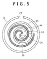
- the expander 14 includes a fixed scroll 65 that is formed in a scroll shape, a whirl scroll 66 that moves while partially contacting the fixed scroll 65, and the casing 12 that accommodates both scrolls 65 and 66.
- the introduction port 26 is formed at the center portion of the casing 12 in the radial direction, and the discharge port 27 is formed in the outer peripheral portion of the casing 12.
- the working medium that is introduced into the expansion chamber 44 between the fixed scroll 65 and the whirl scroll 66 through the introduction port 26 operates the whirl scroll 66.
- the volume inside the expansion chamber 44 gradually increases, so that the working medium is gradually expanded.
- one end of the first communication portion 53 is opened to the intermediate portion of the casing 12 in the radial direction, a part of the working medium during the expansion process is led to the front portion 12c inside the generator chamber 12b through the first communication portion 53.
- the working medium may be circulated inside the generator chamber 12b by the pressure difference between the pressure of the working medium inside the expansion chamber 44 and the pressure of the working medium inside the discharge chamber 30.
- a power generation apparatus includes: an expander; a generator that includes a generator rotor driven by the expander and a stator disposed outside the generator rotor in the radial direction; and a casing that includes an expander chamber accommodating the expander and a generator chamber accommodating the generator.
- the casing includes a first communication portion that causes an expansion chamber which gradually expands a working medium by the expander in the expander chamber to communicate with a front generator portion which is located nearer the expansion chamber than the generator in the generator chamber and a second communication portion that causes a portion which is a downstream portion from the expansion chamber and is located near the expansion chamber with respect to the generator to communicate with the front generator portion.
Landscapes
- Engineering & Computer Science (AREA)
- Mechanical Engineering (AREA)
- General Engineering & Computer Science (AREA)
- Power Engineering (AREA)
- Physics & Mathematics (AREA)
- Fluid Mechanics (AREA)
- Motor Or Generator Cooling System (AREA)
- Connection Of Motors, Electrical Generators, Mechanical Devices, And The Like (AREA)
Abstract
Description
- The present invention relates to a power generation apparatus and a power generation system.
- Hitherto, there is known a power generation apparatus that drives an expander by a working medium and generates power by a generator directly coupled to the expander. A power generation apparatus disclosed in
JP 2004-353571 A JP 2012-147567 A - In the power generation apparatus disclosed in
JP 2012-147567 A - Therefore, the present invention is made in view of the related art, and an object thereof is to provide a power generation apparatus capable of cooling a generator by a simple configuration while suppressing a working medium circulation resistance generated when cooling the generator.
- In order to attain the above-described object, according to the present invention, there is provided a power generation apparatus including: an expander; a generator that includes a rotor driven by the expander and a stator disposed outside the rotor in the radial direction; and a casing that includes an expander chamber accommodating the expander and a generator chamber accommodating the generator, in which the casing includes a first communication portion that causes an expansion chamber which gradually expands a working medium by the expander in the expander chamber to communicate with a front generator portion which is located nearer the expansion chamber than the generator in the generator chamber, and a second communication portion that causes a portion which is a downstream portion from the expansion chamber in the working medium flow direction and is located near the expansion chamber with respect to the generator to communicate with the front generator portion.
- In the present invention, the expansion chamber communicates with the generator chamber by the first communication portion. Meanwhile, the generator chamber communicates with the downstream portion from the expansion chamber by the second communication portion. Since the pressure of the downstream portion from the expansion chamber is lower than the pressure inside the expansion chamber during the expansion process, the working medium inside the expansion chamber flows to the generator chamber through the first communication portion due to a pressure difference therebetween, and then the working medium flows to the downstream portion from the expansion chamber through the second communication portion. For this reason, the generator may be cooled by the working medium inside the generator chamber. Accordingly, it is possible to simply cool the generator by the working medium without newly providing a cooling pipe. Further, since the second communication portion causes the portion which is located near the expansion chamber with respect to the generator and is located at the downstream side of the expansion chamber to communicate with the front generator portion, the working medium flows inside the generator chamber without flowing inside the generator (or slightly flowing inside the generator). For this reason, the working medium circulation resistance inside the generator chamber does not increase. Accordingly, the working medium may be effectively caused to flow by the pressure difference, and the power generation efficiency may be prevented from being degraded. Further, since the working medium does not flow inside the generator or slightly flows inside the generator, there is a low possibility that foreign matter intrudes into the generator even when the foreign matter is contained in the working medium.
- Here, a coil of the stator may face a flow passage in which the working medium flows inside the front generator portion. In this aspect, since the coil of the stator faces the working medium flow passage, the coil that easily emits heat may be efficiently cooled.
- The casing may include a step portion that is located at the rear side of the stator and protrudes inward in the radial direction. In this case, a stator core of the stator may include a radial contact portion that contacts an inner peripheral surface of the casing in the radial direction and an axial contact portion that contacts the step portion in the axial direction.
- In this aspect, the heat of the stator core is directly transmitted to the casing, but the heat may be emitted through the casing.
- Further, since the casing is provided with the step portion, the stator may be easily positioned in the axial direction. When the position of the step portion in the axial direction is adjusted, the width of the flow passage may be easily designed.
- A downstream portion from the expansion chamber may be a discharge chamber of the expander. In this aspect, since the second communication portion is formed so as to cause the generator chamber to communicate with the discharge chamber, the complex configuration inside the casing may be suppressed, and hence an advantage in cost may be obtained.
- According to the present invention, there is provided a power generation system including: an evaporator that evaporates a working medium; the above-described power generation apparatus; a condenser that condenses the working medium expanded by the expander of the power generation apparatus; and a pump that introduces the working medium condensed by the condenser into the evaporator. In the present invention, the power generation apparatus may generate power while circulating the working medium in the evaporator, the expander, and the condenser.
- The power generation system may be an on-vehicle system. In this aspect, since the power generation system is used while being mounted on the vehicle, the power generation system may be used as a power supply source necessary for the vehicle.
- As described above, according to the present invention, it is possible to suppress the working medium circulation resistance generated when the generator is cooled and to cool the generator by a simple configuration.
-
-
FIG. 1 is a diagram schematically illustrating the overall configuration of a power generation system according to an embodiment of the present invention. -
FIG. 2 is a cross-sectional view taken along the line II-II ofFIG. 1 . -
FIG. 3 is a cross-sectional view taken along the line III-III ofFIG. 1 . -
FIG. 4 is a partially enlarged view illustrating a power generation apparatus provided in the power generation system. -
FIG. 5 is a diagram schematically illustrating an expander according to another embodiment of the present invention. - Hereinafter, an embodiment of the present invention will be described in detail with reference to the drawings.
- As illustrated in
FIG. 1 , apower generation system 1 according to the embodiment is a power generation system that uses a Rankine cycle, and includes apower generation apparatus 2, acondenser 6, acirculation pump 8, and anevaporator 10. Thepower generation apparatus 2, thecondenser 6, thecirculation pump 8, and theevaporator 10 are provided in acirculation flow passage 4 in this order. A working medium circulates in thecirculation flow passage 4. As the working medium, for example, a cooling medium such as R245fa (1, 1, 1, 3, 3-Pentafluoropropane) having a low boiling point is used. Accordingly, the power generation system is of a binary power generation type that recovers power from the low-temperature waste heat. Furthermore, the power generation system is configured as an on-vehicle system. - The
power generation apparatus 2 includes a screw-type expander (hereinafter, simply referred to as an expander) 14, agenerator 16, and acasing 12 that accommodates theexpander 14 and thegenerator 16 while these components are connected to each other. Thepower generation apparatus 2 extracts a force for driving thegenerator 16 by expanding a gas-phase working medium in theexpander 14. Furthermore, thepower generation apparatus 2 will be described in detail later. - The
condenser 6 condenses the gas-phase working medium discharged from theexpander 14 so as to become a liquid-phase working medium. Thecondenser 6 includes a workingmedium flow passage 6a in which the gas-phase working medium flows and a coolingmedium flow passage 6b in which the cooling medium flows by the connection with theflow passage 61 in which the cooling medium supplied from the outside flows. The working medium that flows in the workingmedium flow passage 6a exchanges heat with the cooling medium flowing in the coolingmedium flow passage 6b so as to condense the cooling medium. - The
circulation pump 8 is provided at the downstream side (between theevaporator 10 and the condenser 6) of thecondenser 6 in thecirculation flow passage 4 so as to circulate the working medium inside thecirculation flow passage 4. Thecirculation pump 8 pressurizes the liquid-phase working medium condensed by thecondenser 6 to a predetermined pressure and sends the pressurized working medium to theevaporator 10. As thecirculation pump 8, a centrifugal pump that includes an impeller as a rotor or a gear pump that includes a pair of gears as a rotor is used. - The
evaporator 10 is provided at the downstream side (between thecirculation pump 8 and the power generation apparatus 2) of thecirculation pump 8 in thecirculation flow passage 4. Theevaporator 10 includes a workingmedium flow passage 10a in which the working medium flows and a heatingmedium flow passage 10b in which the heating medium flows. The heatingmedium flow passage 10b is connected to aheating medium circuit 62, and the heating medium supplied from an external heat source flows in the heatingmedium flow passage 10b. The working medium that flows in the workingmedium flow passage 10a exchanges heat with the heating medium flowing in the heatingmedium flow passage 10b, and is then evaporated. - With the above-described configuration, in the power generation system according to the embodiment, a circulation circuit is configured in which the working medium flows through the
circulation flow passage 4 in order of theevaporator 10, thepower generation apparatus 2, thecondenser 6, and thecirculation pump 8. - Next, the configuration of the
power generation apparatus 2 will be described in detail. - The
expander 14 of thepower generation apparatus 2 includes a pair ofexpander rotors 32 respectively rotating about the axes. Eachexpander rotor 32 is configured as a screw rotor that includes teeth formed in a spiral shape along the outer peripheral surface thereof. As illustrated inFIG. 2 , the teeth of bothexpander rotors 32 engage with one another, and the engagement position gradually moves in the axial direction with the rotation of therespective rotors 32. - As illustrated in
FIG. 1 , eachexpander rotor 32 includes arotation shaft 34. Eachrotation shaft 34 includes afirst shaft portion 34a that extends from theexpander rotor 32 toward one side in the axial direction and asecond shaft portion 34b that extends from theexpander rotor 32 toward the other side in the axial direction. - The
generator 16 includes agenerator rotor 38 that is connected to oneexpander rotor 32 through thesecond shaft portion 34b and astator 40 that is disposed so as to surround thegenerator rotor 38. That is, thegenerator 16 is configured as an inner rotor type generator in which thegenerator rotor 38 is disposed inside thestator 40. Thestator 40 includes astator core 40a and acoil 40b that is attached to thestator core 40a. Thegenerator rotor 38 includes an iron core and a coil. Thegenerator rotor 38 rotates along with theexpander rotor 32. - The
casing 12 that accommodates theexpander 14 and thegenerator 16 includes acylindrical body portion 22 of which both ends are opened, afirst lid portion 23 that is coupled to one end of thebody portion 22 so as to block one end side opening of thebody portion 22, and asecond lid portion 24 that is coupled to the other end of thebody portion 22 so as to block the other end side opening of thebody portion 22. All of thebody portion 22, thefirst lid portion 23, and thesecond lid portion 24 are made of metal. Thefirst lid portion 23 is formed in a bottomed cylindrical shape, and abottom portion 23a of thefirst lid portion 23 is provided with anintroduction port 26 connected with thecirculation flow passage 4. Thesecond lid portion 24 is formed in a bottomed cylindrical shape, and the bottom portion of thesecond lid portion 24 is blocked differently from thefirst lid portion 23. Thebody portion 22 is provided with adischarge port 27 that is connected with thecirculation flow passage 4. - A
partition wall portion 22a is formed at the intermediate portion of thebody portion 22 in the axial direction. Anexpander chamber 12a that accommodates theexpander 14 and agenerator chamber 12b that accommodates thegenerator 16 are formed inside thecasing 12 by thepartition wall portion 22a. Thepartition wall portion 22a is provided with a through-hole that penetrates the partition wall portion in the axial direction, and abearing 28 that rotatably supports thesecond shaft portion 34b is fitted into the through-hole. Twobearings 28 are provided so as to correspond to the respectivesecond shaft portions 34b while being located between theexpander rotor 32 and thegenerator rotor 38. - The
expander chamber 12a is divided into aninlet chamber 29 and adischarge chamber 30 by apartition portion 22b. Thepartition portion 22b is provided so as to be located at the opposite side to thegenerator 16 with respect to thepartition wall portion 22a and to form a space between thepartition wall portion 22a and the partition portion. Theinlet chamber 29 is a space that is defined by thepartition portion 22b and thefirst lid portion 23, and is a space in which theintroduction port 26 is opened inside theexpander chamber 12a. Thedischarge chamber 30 is a space that is defined by thepartition portion 22b and thepartition wall portion 22a, and is a space in which thedischarge port 27 is opened inside theexpander chamber 12a. - The
partition portion 22b is provided with an opening portion, and theexpander rotor 32 is disposed in the opening portion. Thepartition portion 22b includes an upper portion that is formed so as to protrude from the upper wall of thebody portion 22 toward the inside (the lower side inFIG. 1 ) and a lower portion that extends from the bottom wall of thebody portion 22 toward the inside (the upper side inFIG. 1 ). As illustrated inFIG. 2 , a lower surface 22c of the upper portion is formed in a double-circular-arc shape corresponding to the outer shapes of theexpander rotors 32, and theupper surface 22d of the lower portion is formed in a double-circular-arc shape corresponding to the outer shapes of theexpander rotors 32. Then, the pair ofexpander rotors 32 is disposed inside an opening portion that is formed between the lower surface 22c of the upper portion and theupper surface 22d of the lower portion. A space that is formed among theexpander rotor 32, the lower surface 22c of the upper portion, and theupper surface 22d of the lower portion becomes a space into which the working medium is introduced, and a space that is formed between the engaging teeth inside the space becomes anexpansion chamber 44. Theexpansion chamber 44 moves in the axial direction with the rotation of theexpander rotor 32 so that the volume thereof gradually increases. For this reason, the working medium is gradually expanded inside theexpansion chamber 44. - As illustrated in
FIGS. 1 and3 , abearing holding portion 47 that holdsbearings 46 of thefirst shaft portions 34a is fixed to one end of thepartition portion 22b in the axial direction. As illustrated inFIG. 3 , the pair ofbearings 46 is attached to thebearing holding portion 47, and the pair offirst shaft portions 34a is rotatably supported by thebearings 46. - An
inlet port 49 is formed in the upper portion of thepartition portion 22b by notching one end in the axial direction (the end near the first lid portion 23). Theinlet port 49 causes theinlet chamber 29 to communicate with the inside of the opening portion of thepartition portion 22b, and the working medium inside theinlet chamber 29 is introduced into the opening portion through theinlet port 49 that is located at the upper side of one end of the expander rotor 32 (the end near the first lid portion 23). - The lower portion of the
partition portion 22b supports one end of theexpander rotor 32. For this reason, theexpansion chamber 44 communicates with thedischarge chamber 30 at the other end of the expander rotor 32 (the end near the second lid portion 24). An opening (outlet port 50) that causes theexpansion chamber 44 and thedischarge chamber 30 to communicate with each other is located at the lower side of theexpander rotor 32, and the working medium that is expanded inside theexpansion chamber 44 is discharged to thedischarge chamber 30 through theoutlet port 50. - The
generator chamber 12b is a space that is defined by thepartition wall portion 22a of thebody portion 22 and thesecond lid portion 24. Thegenerator 16 that is accommodated in thegenerator chamber 12b is located at the intermediate portion of thegenerator chamber 12b in the axial direction. Accordingly, the inside of thegenerator chamber 12b is divided into afront portion 12c and arear portion 12d by thegenerator 16. Thefront portion 12c is a space that is located at the front side (the side near theexpansion chamber 44 with respect to the generator 16) from thegenerator 16. Therear portion 12d is a space that is located at the rear side (the side opposite to theexpansion chamber 44 with respect to the generator 16) from thegenerator 16. Thefront portion 12c communicates with therear portion 12d through the gap formed between thestator core 40a and thegenerator rotor 38. - As illustrated in
FIG. 4 , thestator core 40a of thegenerator 16 is positioned by astep portion 52 formed in thesecond lid portion 24 of thecasing 12, and then is fixed to thesecond lid portion 24. Thestep portion 52 is formed in acylinder portion 24b, which is formed in the peripheral edge of thebottom portion 24a in thesecond lid portion 24, so as to protrude inward in the radial direction. Thestep portion 52 is continuously formed in the circumferential direction of thecylinder portion 24b, but may be intermittently formed in the circumferential direction. Anend surface 52a near thebody portion 22 in thestep portion 52 becomes a surface that is substantially perpendicular to the axial direction. - The
stator core 40a is pressed into thesecond lid portion 24, the outer peripheral surface (radial contact portion) of thestator core 40a contacts the inner peripheral surface of thecylinder portion 24b of thesecond lid portion 24, and one end surface (axial contact portion) of thestator core 40a contacts theend surface 52a near thebody portion 22 in thestep portion 52. Accordingly, thegenerator 16 is held at a predetermined position inside thecasing 12 by thesecond lid portion 24. - As illustrated in
FIG. 1 , thecasing 12 is provided with afirst communication portion 53 and asecond communication portion 54. Thefirst communication portion 53 is formed as a through-hole that penetrates thepartition wall portion 22a at the upper position from theexpander rotor 32. One end of thefirst communication portion 53 faces the intermediate portion of theexpander rotor 32 in the axial direction at the upper portion of thepartition portion 22b. For this reason, thefirst communication portion 53 communicates with theexpansion chamber 44 during the expansion process. The other end of thefirst communication portion 53 faces thefront portion 12c of thegenerator chamber 12b. Accordingly, thefirst communication portion 53 causes theexpansion chamber 44 to communicate with thefront portion 12c of thegenerator chamber 12b. - The
second communication portion 54 is formed as a through-hole that penetrates thepartition wall portion 22a at the lower position from theexpander rotor 32. One end of thesecond communication portion 54 faces thedischarge chamber 30, and the other end thereof faces thefront portion 12c of thegenerator chamber 12b. Accordingly, thesecond communication portion 54 causes thefront portion 12c of thegenerator chamber 12b to communicate with thedischarge chamber 30. - Here, the running operation of the power generation system according to the embodiment will be described. When the
circulation pump 8 is driven, the liquid-phase working medium that is sent from thecirculation pump 8 flows into the workingmedium flow passage 10a of theevaporator 10. The working medium is evaporated while being heated by the heating medium flowing in the heatingmedium flow passage 10b. The working medium that is evaporated by theevaporator 10 is introduced from theintroduction port 26 into theinlet chamber 29 of thepower generation apparatus 2. The working medium that flows into theinlet chamber 29 is introduced from theinlet port 49 formed in thepartition portion 22b into theexpansion chamber 44. When the working medium is introduced into theexpansion chamber 44, theexpander rotor 32 is rotationally driven, so that thegenerator rotor 38 of thegenerator 16 rotates to generate power. At this time, theexpansion chamber 44 gradually expands the working medium while moving in the axial direction with the rotation of theexpander rotor 32. Accordingly, the pressure of the working medium inside theexpansion chamber 44 gradually decreases. Then, the working medium having been used to generate power is discharged from theoutlet port 50 into thedischarge chamber 30. Since theexpansion chamber 44 communicates with thefirst communication portion 53 during the expansion process, a part of the working medium inside theexpansion chamber 44 is introduced into thefront portion 12c inside thegenerator chamber 12b through thefirst communication portion 53. The working medium flows inside thefront portion 12c, and cools thecoil 40b of thestator 40 and thegenerator rotor 38 at this time. Then, the working medium inside thefront portion 12c is joined to the working medium inside thedischarge chamber 30 through thesecond communication portion 54. That is, since the pressure inside theexpansion chamber 44 during the expansion process is higher than the pressure inside thedischarge chamber 30, the working medium is circulated inside thegenerator chamber 12b due to a pressure difference therebetween. At this time, since thesecond lid portion 24 constituting therear portion 12d is blocked in thegenerator chamber 12b, the working medium inside thefront portion 12c scarcely flows into therear portion 12d. - The working medium inside the
discharge chamber 30 is discharged to thecirculation flow passage 4 through thedischarge port 27. The gas-phase working medium that is discharged from thepower generation apparatus 2 is introduced into the workingmedium flow passage 6a of thecondenser 6. In thecondenser 6, the working medium is condensed while being cooled by the cooling medium flowing in the coolingmedium flow passage 6b. The liquid-phase working medium flows in thecirculation flow passage 4 so as to be suctioned into thecirculation pump 8. In thecirculation flow passage 4, such a circulation is repeated, and hence power is generated in thepower generation apparatus 2. - As described above, in the embodiment, the
expansion chamber 44 and thegenerator chamber 12b communicate with each other by thefirst communication portion 53. Meanwhile, thegenerator chamber 12b communicates with the downstream portion from theexpansion chamber 44 by thesecond communication portion 54. Since the pressure of the downstream portion from theexpansion chamber 44 is lower than the pressure inside theexpansion chamber 44 during the expansion process, the working medium inside theexpansion chamber 44 flows to thegenerator chamber 12b through thefirst communication portion 53 due to a pressure difference therebetween, and then the working medium flows to the downstream portion from theexpansion chamber 44 through thesecond communication portion 54. For this reason, thegenerator 16 may be cooled by the working medium inside thegenerator chamber 12b. Accordingly, it is possible to simply cool the generator by the working medium without newly providing a cooling pipe. Further, since thesecond communication portion 54 causes a portion which is located near theexpansion chamber 44 with respect to thegenerator 16 and is located at the downstream side from theexpansion chamber 44 to communicate with thefront generator portion 12c, the working medium flows inside thegenerator chamber 12b without flowing inside the generator 16 (or while slightly flowing inside the generator 16). For this reason, the working medium circulation resistance inside thegenerator chamber 12b does not increase. Accordingly, the working medium may be effectively caused to flow by the pressure difference, and the power generation efficiency may be prevented from being degraded. Further, since the working medium does not flow inside thegenerator 16 or slightly flows inside thegenerator 16, there is a low possibility that foreign matter intrudes into thegenerator 16 even when the foreign matter is contained in the working medium. - Further, in the embodiment, since the
coil 40b of thestator 40 faces the flow passage in which the working medium flows inside thefront portion 12c of thegenerator chamber 12b, thecoil 40b that easily emits heat may be effectively cooled. - Further, in the embodiment, since the
stator core 40a is coupled to thecasing 12, the heat of thestator core 40a is directly transmitted to thecasing 12, but this heat may be emitted through thecasing 12. Further, since thecasing 12 is provided with thestep portion 52, thestator 40 may be easily positioned in the axial direction. In addition, when the position of thestep portion 52 in the axial direction is adjusted, the width of the flow passage may be easily designed. Accordingly, since the flow rate of the working medium flowing inside thefront portion 12c is adjusted, thegenerator 16 may be efficiently cooler, and the amount of the working medium that drives theexpander 14 may be prevented from being excessively decreased. - Further, in the embodiment, since the
second communication portion 54 is connected to thedischarge chamber 30, the complex configuration inside thecasing 12 may be prevented, and hence an advantage in cost may be obtained. - Furthermore, the present invention is not limited to the above-described embodiment, and various modifications and improvements may be made without departing from the spirit of the present invention. The
power generation system 1 of the above-described embodiment is configured as the on-vehicle system, but the present invention is not limited thereto. For example, a power generation system may be configured which generates power by recovering the heat of steam or the like using a heating medium that is steam extracted from a well (steam well), steam generated by a solar energy collector using solar heat as a heat source other than steam discharged from a factory or the like, steam or hot water generated from exhaust heat of an engine or a compressor, or steam or hot water generated from a boiler using biomass or fossil fuel as a heat source. - In the above-described embodiment, a configuration has been described in which the
second communication portion 54 is connected to thedischarge chamber 30, but the present invention is not limited thereto. For example, thesecond communication portion 54 may not be formed so as to penetrate thepartition wall portion 22a, but may be formed so as to penetrate thebody portion 22 of thecasing 12 and to be connected to thecirculation flow passage 4 by a pipe or may be formed so as to penetrate thebody portion 22 and to be directly connected to thecondenser 6 by the pipe. - In the above-described embodiment, the
expander 14 includes the pair ofexpander rotors 32 formed as screw rotors having spiral teeth, but the present invention is not limited to this configuration. For example, as illustrated inFIG. 5 , theexpander 14 may be configured as a scroll-type expander. In this case, theexpander 14 includes a fixedscroll 65 that is formed in a scroll shape, awhirl scroll 66 that moves while partially contacting the fixedscroll 65, and thecasing 12 that accommodates bothscrolls introduction port 26 is formed at the center portion of thecasing 12 in the radial direction, and thedischarge port 27 is formed in the outer peripheral portion of thecasing 12. Then, the working medium that is introduced into theexpansion chamber 44 between the fixedscroll 65 and thewhirl scroll 66 through theintroduction port 26 operates thewhirl scroll 66. When thewhirl scroll 66 rotates, the volume inside theexpansion chamber 44 gradually increases, so that the working medium is gradually expanded. Since one end of thefirst communication portion 53 is opened to the intermediate portion of thecasing 12 in the radial direction, a part of the working medium during the expansion process is led to thefront portion 12c inside thegenerator chamber 12b through thefirst communication portion 53. Even in this configuration, the working medium may be circulated inside thegenerator chamber 12b by the pressure difference between the pressure of the working medium inside theexpansion chamber 44 and the pressure of the working medium inside thedischarge chamber 30. - A power generation apparatus according to the present invention includes: an expander; a generator that includes a generator rotor driven by the expander and a stator disposed outside the generator rotor in the radial direction; and a casing that includes an expander chamber accommodating the expander and a generator chamber accommodating the generator. The casing includes a first communication portion that causes an expansion chamber which gradually expands a working medium by the expander in the expander chamber to communicate with a front generator portion which is located nearer the expansion chamber than the generator in the generator chamber and a second communication portion that causes a portion which is a downstream portion from the expansion chamber and is located near the expansion chamber with respect to the generator to communicate with the front generator portion.
Claims (6)
- A power generation apparatus, comprising:an expander;a generator that includes a rotor driven by the expander and a stator disposed outside the rotor in the radial direction; anda casing that includes an expander chamber accommodating the expander and a generator chamber accommodating the generator,wherein the casing includes a first communication portion that causes an expansion chamber which gradually expands a working medium by the expander in the expander chamber to communicate with a front generator portion which is located nearer the expansion chamber than the generator in the generator chamber, and a second communication portion that causes a portion which is a downstream portion from the expansion chamber in the working medium flow direction and is located near the expansion chamber with respect to the generator to communicate with the front generator portion.
- The power generation apparatus according to claim 1,
wherein a coil of the stator faces a flow passage in which the working medium flows inside the front generator portion. - The power generation apparatus according to claim 2,
wherein the casing includes a step portion that is located at the rear side of the stator and protrudes inward in the radial direction, and
wherein a stator core of the stator includes a radial contact portion that contacts an inner peripheral surface of the casing in the radial direction and an axial contact portion that contacts the step portion in the axial direction. - The power generation apparatus according to claim 1,
wherein a downstream portion from the expansion chamber is a discharge chamber of the expander. - A power generation system comprising:an evaporator that evaporates a working medium;the power generation apparatus according to claim 1;a condenser that condenses the working medium expanded by the expander of the power generation apparatus; anda pump that introduces the working medium condensed by the condenser into the evaporator.
- The power generation system according to claim 5,
wherein the power generation system is an on-vehicle system.
Applications Claiming Priority (1)
| Application Number | Priority Date | Filing Date | Title |
|---|---|---|---|
| JP2013062146A JP5891192B2 (en) | 2013-03-25 | 2013-03-25 | Power generation device and power generation system |
Publications (2)
| Publication Number | Publication Date |
|---|---|
| EP2784266A2 true EP2784266A2 (en) | 2014-10-01 |
| EP2784266A3 EP2784266A3 (en) | 2017-12-13 |
Family
ID=49943210
Family Applications (1)
| Application Number | Title | Priority Date | Filing Date |
|---|---|---|---|
| EP14150935.6A Withdrawn EP2784266A3 (en) | 2013-03-25 | 2014-01-13 | Power generation apparatus and system |
Country Status (5)
| Country | Link |
|---|---|
| US (1) | US9618020B2 (en) |
| EP (1) | EP2784266A3 (en) |
| JP (1) | JP5891192B2 (en) |
| KR (1) | KR101533916B1 (en) |
| CN (1) | CN104074566B (en) |
Cited By (2)
| Publication number | Priority date | Publication date | Assignee | Title |
|---|---|---|---|---|
| EP3812589A1 (en) * | 2019-10-21 | 2021-04-28 | Emerson Climate Technologies GmbH | Compressor cooling with suction fluid |
| IT202100019787A1 (en) * | 2021-07-26 | 2023-01-26 | Fluid O Tech Srl | IMPROVED SCREW PUMP, ESPECIALLY FOR COOLING SYSTEMS. |
Families Citing this family (4)
| Publication number | Priority date | Publication date | Assignee | Title |
|---|---|---|---|---|
| CN104196571B (en) * | 2014-08-18 | 2017-10-03 | 罗显平 | A kind of method and its device for improving turbine engine efficiency |
| JP6815911B2 (en) * | 2017-03-22 | 2021-01-20 | 株式会社神戸製鋼所 | Thermal energy recovery device |
| CN108343477A (en) * | 2018-01-30 | 2018-07-31 | 南京普国科技有限公司 | A kind of efficient automobile pressure-air turbine generator |
| CN113565586A (en) * | 2021-08-27 | 2021-10-29 | 北京工业大学 | A closed generator exhaust-spray cooling system for organic Rankine cycle |
Citations (2)
| Publication number | Priority date | Publication date | Assignee | Title |
|---|---|---|---|---|
| JP2004353571A (en) | 2003-05-29 | 2004-12-16 | Ebara Corp | Power generating device and power generating method |
| JP2012147567A (en) | 2011-01-12 | 2012-08-02 | Kobe Steel Ltd | Power generation system |
Family Cites Families (36)
| Publication number | Priority date | Publication date | Assignee | Title |
|---|---|---|---|---|
| US3024366A (en) * | 1958-06-11 | 1962-03-06 | Yanagimachi Masanosuke | Electric generator system |
| BE871024A (en) * | 1978-10-05 | 1979-04-05 | Acec | EXPANSION TURBINE ASSEMBLY - CURRENT GENERATOR. |
| EP0156606B1 (en) * | 1984-03-17 | 1991-02-27 | Isuzu Motors Limited | Generator device |
| US5211026A (en) * | 1991-08-19 | 1993-05-18 | American Standard Inc. | Combination lift piston/axial port unloader arrangement for a screw compresser |
| US5559379A (en) * | 1993-02-03 | 1996-09-24 | Nartron Corporation | Induction air driven alternator and method for converting intake air into current |
| JPH0988501A (en) * | 1995-09-22 | 1997-03-31 | Hisaka Works Ltd | Screw turbine and binary power generator using the same |
| US5659205A (en) * | 1996-01-11 | 1997-08-19 | Ebara International Corporation | Hydraulic turbine power generator incorporating axial thrust equalization means |
| JPH10290543A (en) * | 1997-04-15 | 1998-10-27 | Toyota Motor Corp | motor |
| JP3499110B2 (en) * | 1997-08-11 | 2004-02-23 | 株式会社神戸製鋼所 | Oil-cooled screw compressor |
| JP3684071B2 (en) * | 1998-06-05 | 2005-08-17 | 株式会社神戸製鋼所 | Screw refrigeration system |
| JP2003343203A (en) * | 2002-05-30 | 2003-12-03 | Anest Iwata Corp | Scroll type fluid machine provided with compression and expansion parts |
| KR100611271B1 (en) * | 2004-04-27 | 2006-08-10 | 가부시키가이샤 고베 세이코쇼 | Two stage screw refrigerator |
| DE602004002915T2 (en) * | 2004-09-08 | 2007-06-28 | Anest Iwata Corp., Yokohama | Scroll fluid machine |
| JP2006200434A (en) * | 2005-01-20 | 2006-08-03 | Sanden Corp | Power generating device |
| JP2006230145A (en) * | 2005-02-18 | 2006-08-31 | Ebara Corp | Submerged turbine generator |
| JP2006242133A (en) * | 2005-03-04 | 2006-09-14 | Denso Corp | Fluid machinery |
| US20080122226A1 (en) * | 2006-11-29 | 2008-05-29 | Ebara International Corporation | Compact assemblies for high efficiency performance of cryogenic liquefied gas expanders and pumps |
| US7841306B2 (en) * | 2007-04-16 | 2010-11-30 | Calnetix Power Solutions, Inc. | Recovering heat energy |
| US7638892B2 (en) * | 2007-04-16 | 2009-12-29 | Calnetix, Inc. | Generating energy from fluid expansion |
| JP5084342B2 (en) * | 2007-04-27 | 2012-11-28 | サンデン株式会社 | Fluid machine, Rankine circuit using the fluid machine, and vehicle waste heat utilization system |
| JP5197141B2 (en) | 2008-05-12 | 2013-05-15 | 株式会社神戸製鋼所 | Two-stage screw compressor and refrigeration system |
| JP5081894B2 (en) * | 2009-12-14 | 2012-11-28 | 株式会社神戸製鋼所 | Power generator |
| JP5414811B2 (en) * | 2010-01-19 | 2014-02-12 | 三菱電機株式会社 | Positive displacement expander and refrigeration cycle apparatus using the positive displacement expander |
| US8400005B2 (en) * | 2010-05-19 | 2013-03-19 | General Electric Company | Generating energy from fluid expansion |
| WO2012020630A1 (en) * | 2010-08-09 | 2012-02-16 | 株式会社 豊田自動織機 | Waste heat utilization apparatus |
| JP5318062B2 (en) * | 2010-10-04 | 2013-10-16 | 株式会社神戸製鋼所 | Screw expander |
| CN101975094B (en) * | 2010-11-08 | 2012-10-17 | 上海维尔泰克螺杆机械有限公司 | Liquid pump of screw expander |
| CN201904689U (en) * | 2010-11-16 | 2011-07-20 | 上海维尔泰克螺杆机械有限公司 | Screw expansion generating set |
| CN102061944B (en) * | 2010-11-16 | 2012-11-28 | 上海维尔泰克螺杆机械有限公司 | Screw expansion generating device |
| JP5752403B2 (en) * | 2010-12-13 | 2015-07-22 | 株式会社神戸製鋼所 | Power generation system |
| US9093871B2 (en) * | 2010-12-21 | 2015-07-28 | Calnetix Technologies, L.L.C. | Bidirectional pumping and energy recovery system |
| JP5751885B2 (en) | 2011-03-29 | 2015-07-22 | 株式会社神戸製鋼所 | Power generation system and power generation apparatus |
| JP2012246872A (en) * | 2011-05-30 | 2012-12-13 | Toyota Industries Corp | Waste heat recovery mechanism, and waste heat recovery apparatus |
| JP2013169029A (en) * | 2012-02-14 | 2013-08-29 | Kobe Steel Ltd | Power generator |
| JP5715111B2 (en) * | 2012-12-12 | 2015-05-07 | 株式会社神戸製鋼所 | Power generation device and power generation system |
| JP6086726B2 (en) * | 2012-12-28 | 2017-03-01 | 三菱重工業株式会社 | Power generation system and power generation method |
-
2013
- 2013-03-25 JP JP2013062146A patent/JP5891192B2/en active Active
-
2014
- 2014-01-13 EP EP14150935.6A patent/EP2784266A3/en not_active Withdrawn
- 2014-01-14 US US14/154,344 patent/US9618020B2/en not_active Expired - Fee Related
- 2014-03-20 KR KR1020140032772A patent/KR101533916B1/en not_active Expired - Fee Related
- 2014-03-25 CN CN201410112917.0A patent/CN104074566B/en not_active Expired - Fee Related
Patent Citations (2)
| Publication number | Priority date | Publication date | Assignee | Title |
|---|---|---|---|---|
| JP2004353571A (en) | 2003-05-29 | 2004-12-16 | Ebara Corp | Power generating device and power generating method |
| JP2012147567A (en) | 2011-01-12 | 2012-08-02 | Kobe Steel Ltd | Power generation system |
Cited By (5)
| Publication number | Priority date | Publication date | Assignee | Title |
|---|---|---|---|---|
| EP3812589A1 (en) * | 2019-10-21 | 2021-04-28 | Emerson Climate Technologies GmbH | Compressor cooling with suction fluid |
| US11906214B2 (en) | 2019-10-21 | 2024-02-20 | Copeland Europe Gmbh | Compressor cooling |
| IT202100019787A1 (en) * | 2021-07-26 | 2023-01-26 | Fluid O Tech Srl | IMPROVED SCREW PUMP, ESPECIALLY FOR COOLING SYSTEMS. |
| EP4124756A1 (en) * | 2021-07-26 | 2023-02-01 | Fluid-O-Tech S.r.l. | Improved screw-spindle pump, particularly for cooling systems |
| US11867178B2 (en) | 2021-07-26 | 2024-01-09 | Fluid-O-Tech S.R.L. | Screw-spindle pump, particularly for cooling systems |
Also Published As
| Publication number | Publication date |
|---|---|
| US20140284931A1 (en) | 2014-09-25 |
| JP2014185609A (en) | 2014-10-02 |
| CN104074566A (en) | 2014-10-01 |
| KR20140117286A (en) | 2014-10-07 |
| KR101533916B1 (en) | 2015-07-03 |
| CN104074566B (en) | 2017-01-04 |
| JP5891192B2 (en) | 2016-03-22 |
| EP2784266A3 (en) | 2017-12-13 |
| US9618020B2 (en) | 2017-04-11 |
Similar Documents
| Publication | Publication Date | Title |
|---|---|---|
| US9618020B2 (en) | Power generation apparatus and power generation system | |
| KR101482879B1 (en) | Power generating apparatus and operation method thereof | |
| JP7266707B2 (en) | Power generation system and method of generating power by operation of such power generation system | |
| US9500101B2 (en) | Power generation apparatus including lubricant separation member | |
| KR101361253B1 (en) | Power generating apparatus | |
| WO2015083458A1 (en) | Coolant pump and binary power generation system using such coolant pump | |
| JP5752403B2 (en) | Power generation system | |
| JP5592305B2 (en) | Power generator | |
| KR20140071911A (en) | Rotary machine drive system | |
| JP6070224B2 (en) | Power generator | |
| EP2808485B1 (en) | Expander | |
| WO2011118348A1 (en) | Complex fluid machine | |
| JP2006200434A (en) | Power generating device | |
| US20120304643A1 (en) | Waste heat recovery mechanism and waste heat recovery apparatus | |
| EP2744989B1 (en) | Compression and energy-recovery unit | |
| JP2013087658A (en) | Waste heat utilization system | |
| KR102046489B1 (en) | Thermal energy recovery device | |
| KR101563629B1 (en) | Generating system for organic rankine cycle | |
| JP6371139B2 (en) | Switching method | |
| KR20160056703A (en) | Engine applied Organic Rankine Cycle | |
| CN113661307B (en) | Power generation system and method of generating power by operating such power generation system | |
| JP2013087659A (en) | Waste heat utilization system | |
| KR20120134022A (en) | Waste heat recovery mechanism and waste heat recovery apparatus | |
| JP2018112151A (en) | Scroll type fluid machine |
Legal Events
| Date | Code | Title | Description |
|---|---|---|---|
| 17P | Request for examination filed |
Effective date: 20140113 |
|
| AK | Designated contracting states |
Kind code of ref document: A2 Designated state(s): AL AT BE BG CH CY CZ DE DK EE ES FI FR GB GR HR HU IE IS IT LI LT LU LV MC MK MT NL NO PL PT RO RS SE SI SK SM TR |
|
| AX | Request for extension of the european patent |
Extension state: BA ME |
|
| PUAI | Public reference made under article 153(3) epc to a published international application that has entered the european phase |
Free format text: ORIGINAL CODE: 0009012 |
|
| PUAL | Search report despatched |
Free format text: ORIGINAL CODE: 0009013 |
|
| RIC1 | Information provided on ipc code assigned before grant |
Ipc: F01C 21/06 20060101ALI20171102BHEP Ipc: F01C 13/00 20060101ALI20171102BHEP Ipc: F01C 1/16 20060101AFI20171102BHEP |
|
| AK | Designated contracting states |
Kind code of ref document: A3 Designated state(s): AL AT BE BG CH CY CZ DE DK EE ES FI FR GB GR HR HU IE IS IT LI LT LU LV MC MK MT NL NO PL PT RO RS SE SI SK SM TR |
|
| AX | Request for extension of the european patent |
Extension state: BA ME |
|
| 17Q | First examination report despatched |
Effective date: 20190412 |
|
| GRAP | Despatch of communication of intention to grant a patent |
Free format text: ORIGINAL CODE: EPIDOSNIGR1 |
|
| INTG | Intention to grant announced |
Effective date: 20200214 |
|
| STAA | Information on the status of an ep patent application or granted ep patent |
Free format text: STATUS: THE APPLICATION IS DEEMED TO BE WITHDRAWN |
|
| 18D | Application deemed to be withdrawn |
Effective date: 20200625 |