EP2784012A1 - Paper aggregation device - Google Patents
Paper aggregation device Download PDFInfo
- Publication number
- EP2784012A1 EP2784012A1 EP11876223.6A EP11876223A EP2784012A1 EP 2784012 A1 EP2784012 A1 EP 2784012A1 EP 11876223 A EP11876223 A EP 11876223A EP 2784012 A1 EP2784012 A1 EP 2784012A1
- Authority
- EP
- European Patent Office
- Prior art keywords
- paper sheet
- conveyer belt
- bill
- holding members
- stacking device
- Prior art date
- Legal status (The legal status is an assumption and is not a legal conclusion. Google has not performed a legal analysis and makes no representation as to the accuracy of the status listed.)
- Withdrawn
Links
- 230000002776 aggregation Effects 0.000 title 1
- 238000004220 aggregation Methods 0.000 title 1
- 239000000126 substance Substances 0.000 claims description 9
- 239000000463 material Substances 0.000 claims description 4
- 238000011144 upstream manufacturing Methods 0.000 claims description 3
- 238000003780 insertion Methods 0.000 description 15
- 230000037431 insertion Effects 0.000 description 15
- 230000004048 modification Effects 0.000 description 4
- 238000012986 modification Methods 0.000 description 4
- 230000008901 benefit Effects 0.000 description 2
- 230000008859 change Effects 0.000 description 2
- 239000013013 elastic material Substances 0.000 description 2
- 239000011347 resin Substances 0.000 description 2
- 229920005989 resin Polymers 0.000 description 2
- 235000001674 Agaricus brunnescens Nutrition 0.000 description 1
- 239000000853 adhesive Substances 0.000 description 1
- 230000001070 adhesive effect Effects 0.000 description 1
- 238000010276 construction Methods 0.000 description 1
- 230000000694 effects Effects 0.000 description 1
- 239000004973 liquid crystal related substance Substances 0.000 description 1
- 230000007246 mechanism Effects 0.000 description 1
- 239000002184 metal Substances 0.000 description 1
- 238000000465 moulding Methods 0.000 description 1
- 238000004904 shortening Methods 0.000 description 1
- 239000013589 supplement Substances 0.000 description 1
Images







Classifications
-
- B—PERFORMING OPERATIONS; TRANSPORTING
- B65—CONVEYING; PACKING; STORING; HANDLING THIN OR FILAMENTARY MATERIAL
- B65H—HANDLING THIN OR FILAMENTARY MATERIAL, e.g. SHEETS, WEBS, CABLES
- B65H29/00—Delivering or advancing articles from machines; Advancing articles to or into piles
- B65H29/02—Delivering or advancing articles from machines; Advancing articles to or into piles by mechanical grippers engaging the leading edge only of the articles
- B65H29/04—Delivering or advancing articles from machines; Advancing articles to or into piles by mechanical grippers engaging the leading edge only of the articles the grippers being carried by endless chains or bands
- B65H29/041—Delivering or advancing articles from machines; Advancing articles to or into piles by mechanical grippers engaging the leading edge only of the articles the grippers being carried by endless chains or bands and introducing into a pile
-
- B—PERFORMING OPERATIONS; TRANSPORTING
- B65—CONVEYING; PACKING; STORING; HANDLING THIN OR FILAMENTARY MATERIAL
- B65H—HANDLING THIN OR FILAMENTARY MATERIAL, e.g. SHEETS, WEBS, CABLES
- B65H29/00—Delivering or advancing articles from machines; Advancing articles to or into piles
- B65H29/20—Delivering or advancing articles from machines; Advancing articles to or into piles by contact with rotating friction members, e.g. rollers, brushes, or cylinders
- B65H29/22—Delivering or advancing articles from machines; Advancing articles to or into piles by contact with rotating friction members, e.g. rollers, brushes, or cylinders and introducing into a pile
-
- B—PERFORMING OPERATIONS; TRANSPORTING
- B65—CONVEYING; PACKING; STORING; HANDLING THIN OR FILAMENTARY MATERIAL
- B65H—HANDLING THIN OR FILAMENTARY MATERIAL, e.g. SHEETS, WEBS, CABLES
- B65H29/00—Delivering or advancing articles from machines; Advancing articles to or into piles
- B65H29/02—Delivering or advancing articles from machines; Advancing articles to or into piles by mechanical grippers engaging the leading edge only of the articles
- B65H29/04—Delivering or advancing articles from machines; Advancing articles to or into piles by mechanical grippers engaging the leading edge only of the articles the grippers being carried by endless chains or bands
- B65H29/045—Details of grippers
- B65H29/048—Self-opening and -closing grippers
-
- B—PERFORMING OPERATIONS; TRANSPORTING
- B65—CONVEYING; PACKING; STORING; HANDLING THIN OR FILAMENTARY MATERIAL
- B65H—HANDLING THIN OR FILAMENTARY MATERIAL, e.g. SHEETS, WEBS, CABLES
- B65H31/00—Pile receivers
-
- B—PERFORMING OPERATIONS; TRANSPORTING
- B65—CONVEYING; PACKING; STORING; HANDLING THIN OR FILAMENTARY MATERIAL
- B65H—HANDLING THIN OR FILAMENTARY MATERIAL, e.g. SHEETS, WEBS, CABLES
- B65H5/00—Feeding articles separated from piles; Feeding articles to machines
- B65H5/004—Feeding articles separated from piles; Feeding articles to machines using electrostatic force
-
- B—PERFORMING OPERATIONS; TRANSPORTING
- B65—CONVEYING; PACKING; STORING; HANDLING THIN OR FILAMENTARY MATERIAL
- B65H—HANDLING THIN OR FILAMENTARY MATERIAL, e.g. SHEETS, WEBS, CABLES
- B65H2404/00—Parts for transporting or guiding the handled material
- B65H2404/20—Belts
- B65H2404/23—Belts with auxiliary handling means
- B65H2404/231—Belts with auxiliary handling means pocket or gripper type
- B65H2404/2311—Belts with auxiliary handling means pocket or gripper type integrally attached to or part of belt material
-
- B—PERFORMING OPERATIONS; TRANSPORTING
- B65—CONVEYING; PACKING; STORING; HANDLING THIN OR FILAMENTARY MATERIAL
- B65H—HANDLING THIN OR FILAMENTARY MATERIAL, e.g. SHEETS, WEBS, CABLES
- B65H2701/00—Handled material; Storage means
- B65H2701/10—Handled articles or webs
- B65H2701/19—Specific article or web
- B65H2701/1912—Banknotes, bills and cheques or the like
Definitions
- the embodiments discussed herein are related to a paper sheet stacking device and, more particularly, to a paper sheet stacking device which can stably perform stacking at the time of stacking paper media, such as bills, conveyed one by one into a bundle.
- ATMs Automatic Teller Machines
- automatic transaction apparatus installed in stores and the like of financial institutions
- paper sheet stacking devices which stack and store bills conveyed one by one.
- a bill is conveyed in a direction parallel with faces of bills stacked in a storage part, and its end slides on a top bill of bills stacked in the storage part. As a result, the bill is introduced into the storage part. Bills are stacked in this way in these paper sheet stacking devices.
- bills conveyed to a storage part have gone into various states different from their original states while they are in circulation. For example, a bill folded is creased. A bill put into a wallet is curled. A bill put into a trouser pocket is crumpled. If a bill in a state different from its original state, such as a bill in a curled state, is at the top of stacked bills, an end of a bill conveyed strikes against a rear end of the bill in a curled state and bills are not arranged properly. This interference between a bill conveyed and bills stacked is liable to occur especially in paper sheet stacking devices into which bills longitudinally conveyed are longitudinally introduced and stored.
- Some proposals for avoiding the above interference between a bill conveyed and bills stacked are known. For example, portions near rear ends of bills stacked are pressed down by a hold-down lever to ensure a bill route in a direction from which bills are conveyed (see, for example, PTL1).
- the hold-down lever is placed on an upstream side of a conveying roller which feeds bills into a storage part.
- One end of the hold-down lever is supported so that it will freely pivot.
- a free end of the hold-down lever touches a top bill of bills stacked in the storage part.
- a bill conveyed is inserted between the free end of the hold-down lever and the top bill, slides on the top bill while lifting the free end of the hold-down lever, and is stacked on the top bill.
- a rear end of a bill which has just been introduced into a storage part is pushed downward by a runner to ensure a bill route in a direction from which bills are conveyed (see, for example, PTL2).
- the runner is arranged coaxially with a conveying roller which feeds bills into the storage part. The runner pushes downward a rear end of a bill which has just been introduced into the storage part to prevent interference between the bill and an end of the following bill. Furthermore, even if a hold-down lever is also used, the runner can effectively prevent the flutter of a rear end of a bill which the hold-down lever cannot prevent.
- An object of the present invention is to provide a paper sheet stacking device which stably stores the following bills even in the case of a top bill of bills stacked being in a state different from its original state.
- a paper sheet stacking device which introduces paper sheets conveyed, which stores the paper sheets in a stacked state, and which includes a paper sheet storage part that receives and stores the paper sheets one by one, an endless conveyer belt looped on a first roller placed on a side over the paper sheet storage part on which the paper sheets are received and a second roller placed on a side over the paper sheet storage part on which the paper sheets are released, and paper sheet holding members each having one end fixed onto an outer surface of the conveyer belt and another end energized to a conveyer belt side on a downstream side in a conveyance direction of a position at which the one end is fixed.
- the paper sheet holding member on the conveyer belt included in the above paper sheet stacking device passes over the first roller, its end portion gets apart from the conveyer belt and the paper sheet holding member receives an end of a paper sheet.
- the paper sheet holding member passes between the first roller and the second roller, the paper sheet holding member holds the paper sheet by grip force.
- the paper sheet holding member passes under the second roller, its end portion gets apart from the conveyer belt.
- the paper sheet holding member releases the paper sheet, makes the paper sheet fall onto stacked paper sheets, and stacks and stores the paper sheet. That is to say, the paper sheet is not pushed from behind into the paper sheet storage part. An end of the paper sheet is drawn in for storage. Therefore, even if a top paper sheet of stacked paper sheets is in a state different from its original state, the paper sheet is stably stored.
- the paper sheet stacking device having the above structure, an end of a paper sheet conveyed is held by grip force of the paper sheet holding member and is drawn in. The grip force is released on a side opposite the reception side. The paper sheet is made to fall onto stacked paper sheets. Therefore, the paper sheet stacking device has the advantage of being able to stably store a paper sheet.
- this paper sheet stacking device an end of a paper sheet is gripped and is drawn in.
- a paper sheet can be conveyed for a long distance, compared with a case where a paper sheet is pushed in by utilizing its rigidity. Therefore, this paper sheet stacking device is suitable for introducing and storing rectangular paper sheets longitudinally.
- FIG. 1 is a perspective view which illustrates the appearance of an ATM to which a paper sheet stacking device according to an embodiment is applied.
- FIG. 2 illustrates an example of the internal structure of a bill processing section of the ATM.
- an ATM includes in the front a customer operation part 1, a bill insertion and dispensing aperture 2, a coin insertion and dispensing aperture 3, a card insertion and ejection aperture 4, and a bankbook insertion and ejection aperture 5.
- the customer operation part 1 is used for operation by which input or instructions regarding a cash transaction are given.
- the customer operation part 1 includes a display portion, such as a liquid crystal panel, and a position input portion, such as a touch pad. Operation by which input is provided to the ATM is performed by touching a screen.
- the bill insertion and dispensing aperture 2 receives bills at the time of a transaction, such as receipt of money, and releases paid bills at the time of a transaction, such as payment of money.
- the coin insertion and dispensing aperture 3 receives coins at the time of a transaction, such as receipt of money, and releases coins paid as change at the time of a transaction, such as receipt of money or remittance.
- the card insertion and ejection aperture 4 handles a cash card used for identifying an individual at the time of the operation of the ATM, a transfer card used at the time of transfer operation, and the like.
- the bankbook insertion and ejection aperture 5 receives a bankbook and prints the contents of a transaction onto it.
- this ATM includes a bill processing parts. That is to say, the ATM includes the bill insertion and dispensing aperture 2 which receives and pays bills, a discrimination part 6 which determines the kind and genuineness of bills, and a temporary pool part 7 which pools received bills after determination, for example, until the conclusion of a transaction.
- the ATM includes a reject part 8 which stores, at the time of the determination that bills are inadequate for reuse being made, the bills as bad bills and storage parts 9, 10, 11, 12, and 13 which store bills.
- the storage parts 9, 10, and 11 are used mainly for storing bills handled at the time of receipt and payment of money.
- the storage parts 12 and 13 are used for storing bills to supplement lack of bills in the storage part 9, 10, or 11 and for storing received bills at the time of the storage parts 9, 10, and 11 being full.
- a paper sheet stacking device can be applied to a part in which bills are stacked in a bundle.
- a paper sheet stacking device is applied to a part which is placed adjacently to the bill insertion and dispensing aperture 2, which receives and stacks in order bills sent one by one from the storage part 9, 10, or 11 at the time of payment of money, and which passes the bills to the bill insertion and dispensing aperture 2 in a bundle.
- a paper sheet stacking device according to the present invention can also be applied to the temporary pool part 7, the reject part 8, and the storage parts 9, 10, 11, 12, and 13.
- FIG. 3 is a side-view which illustrates the rough structure of a paper sheet stacking device according to a first embodiment.
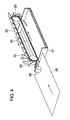
- FIG. 4 is a perspective view which illustrates the rough structure of the paper sheet stacking device according to the first embodiment.
- the paper sheet stacking device includes a paper sheet storage part 21 which stacks and stores bills 20 conveyed one by one.
- a roller 22 is placed on a side over the paper sheet storage part 21 on which the bills 20 are received and a roller 23 is placed on an opposite side over the paper sheet storage part 21 on which the bills 20 are released.
- An endless conveyer belt 24 is looped on the rollers 22 and 23 and bill holding members 25 which hold ends of the bills 20 conveyed are fixed onto an outer surface of the conveyer belt 24.
- a plurality of bill holding members 25 are arranged at determined intervals in a conveyance direction on the outer surface of the conveyer belt 24 in a state in which they overlap with one another.
- the bill holding members 25 may be fixed onto the conveyer belt 24 in the conveyance direction in a state in which they do not overlap with one another, that is to say, in a state in which they are apart from one another. If the bill holding members 25 do not overlap with one another, then FIGS. 3 and 4 indicate the movement of the bill holding members 25 at the time of the conveyer belt 24 operating.
- a pair of conveying rollers 26 and 27 is placed adjacently to the paper sheet stacking device on the side on which the bills 20 are received, and fulfills the function of passing to the paper sheet stacking device bills 20 conveyed longitudinally one by one.
- the bills 20 passed to the paper sheet stacking device are conveyed in a state in which their ends are held by the bill holding members 25 of the paper sheet stacking device. Accordingly, a conveying speed of the conveyer belt 24 is equal to or slightly lower than a speed at which the bills 20 are conveyed by the conveying rollers 26 and 27.
- the ends of the bills 20 supplied by the conveying rollers 26 and 27 are held on the roller 22 side by the conveyer belt 24 and the bill holding members 25.
- the bills 20 are conveyed to the opposite side of the paper sheet storage part 21 in a state in which their ends are held by the conveyer belt 24 and the bill holding members 25.
- the bill holding members 25 release the bills 20 on the roller 23 side. As a result, the bills 20 fall onto a top bill stored in the paper sheet storage part 21 and are stacked.
- the paper sheet storage part 21 has at the bottom a stage which freely goes up and down. Accordingly, when the number of bills 20 stored in the paper sheet storage part 21 changes, control is exercised so that the stage will go up or down. As a result, the position of a top bill 20 does not change materially.
- one conveyer belt 24 onto which the bill holding members 25 are fixed is placed in order to store the bills 20 conveyed in the paper sheet storage part 21.
- a plurality of conveyer belts 24 may be arranged and used at need.
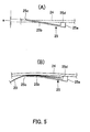
- FIG. 5 are views for describing a relationship between the conveyer belt and a bill holding member of the paper sheet stacking device according to the first embodiment.
- FIG. 5(A) is a view for describing the shape of the bill holding member which is not yet attached to the conveyer belt.
- FIG. 5(B) is a view which illustrates a state of the bill holding member at operation time.
- the bill holding member 25 has a base 25a fixed onto the conveyer belt 24 and a bill pressing portion 25b which extends from the base 25a in a direction close to a direction of conveyance by the conveyer belt 24 and which presses a bill 20 against the conveyer belt 24.
- the base 25a and the bill pressing portion 25b are integrally formed from an elastic material.
- the bill holding member 25 is formed so that it will have the following shape.
- a free end 25c of the bill pressing portion 25b cuts into the conveyer belt 24 by distance a beyond a fitting face 25d of the base 25a.
- the free end 25c of the bill pressing portion 25b functions so as to bend the conveyer belt 24 to a side opposite a side on which the bill holding member 25 is fixed. This flection is grip force for holding the bill 20.
- FIG. 6 are views from a paper sheet storage part side which illustrate a state in which bill holding members are attached to the conveyer belt.
- FIG. 6(A) is a view which illustrates an example of the shape of paper sheet holding members.
- FIG. 6(B) is a view which illustrates another example of the shape of paper sheet holding members.
- the bill holding members 25 are arranged at determined intervals in the direction of conveyance by the conveyer belt 24 so that they will not overlap with one another.
- the bill holding members 25 are arranged in a state in which a base 25a of a bill holding member 25 and a free end 25c of an adjacent bill holding member 25 are apart.
- a notch is cut in a central portion on a base 25a side of each bill holding member 25 and the bill holding members 25 are arranged in a state in which a free end 25c of a bill holding member 25 fits into a notch of an adjacent bill holding member 25.
- FIG. 7 are views for describing another relationship between the conveyer belt and a bill holding member of the paper sheet stacking device according to the first embodiment.
- FIG. 7 (A) is a view for describing the shape of the bill holding member which is not yet attached to the conveyer belt.
- FIG. 7(B) is a view which illustrates a state of the bill holding member at operation time.
- the bill holding members 25 are arranged on the conveyer belt 24 in a state in which they overlap with one another.
- a bill holding member 25 has a base 25a fixed onto the conveyer belt 24 and a bill pressing portion 25b which extends from the base 25a in the direction of conveyance by the conveyer belt 24 and which presses a bill 20 against the conveyer belt 24.
- the bill holding member 25 has a pressing protrusion 25e near a free end 25c of the bill pressing portion 25b on a conveyer belt 24 side.
- the base 25a, the bill pressing portion 25b, and the pressing protrusion 25e are integrally formed from an elastic material.
- the bill holding member 25 is formed so that it will have the following shape.
- the pressing protrusion 25e protrudes by distance b from a face on a paper sheet storage part 21 side of the bill pressing portion 25b to the conveyer belt 24 side.
- a state illustrated in FIG. 7(B) arises. That is to say, a pressing protrusion 25e-1 of the bill holding member 25-1 is on a bill pressing portion 25b-2 of the adjacent bill holding member 25-2 behind and a bill pressing portion 25b-1 bends to the paper sheet storage part 21 side.
- the pressing protrusion 25e-1 of the bill holding member 25-1 touches an area c on an outer surface of the bill pressing portion 25b-2 of the adjacent bill holding member 25-2 behind by a reaction caused by the flection of the bill pressing portion 25b-1.
- grip force for holding the bill 20 is obtained.
- an inner surface of the bill pressing portion 25b-1 of the bill holding member 25-1 touches an end portion d of a base 25a-2 of the adjacent bill holding member 25-2 behind. By doing so, the bill 20 is held. Therefore, the bill 20 is fixed more firmly.
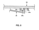
- FIG. 8 is a fragmentary sectional view which illustrates an example of the combination of the conveyer belt and the bill holding member.
- a rib 24a protruding from a surface of the conveyer belt 24 onto which the bill holding member 25 is fixed is formed.
- This rib 24a has a head portion at its end and extends in a crosswise direction of the conveyer belt 24 so as to cross the conveyer belt 24.
- a section of the rib 24a has the shape of a mushroom.
- a more detailed description of the rib 24a is as follows.
- a base 24b of the rib 24a (at which the rib 24a is joined to the conveyer belt 24) is narrow in the direction of conveyance by the conveyer belt 24 and an opposite end portion 24c of the rib 24a is wider in the direction of conveyance by the conveyer belt 24 than the base 24b of the rib 24a.
- a fitting groove 25f whose section has the same shape that a section of the rib 24a has is formed in the base 25a of the bill holding member 25 so that it will extend in the crosswise direction of the conveyer belt 24.
- the bill holding member 25 is fixed onto the conveyer belt 24 by fitting the rib 24a of the conveyer belt 24 into the fitting groove 25f and sliding the bill holding member 25 in the crosswise direction of the conveyer belt 24.
- a portion in which the rib 24a is fitted into the fitting groove 25f is fixed more firmly, for example, by injecting an adhesive into clearance.
- the size of the fitting groove 25f is made approximately equal to or slightly smaller than that of the rib 24a. By doing so, the bill holding member 25 is fixed firmly when the rib 24a is fitted into the fitting groove 25f.
- a part of bill holding members 25 which are significantly expendable can be replaced.
- FIG. 9 is a view for describing a state in which bills are arranged on a bill release side by the bill holding members.
- the paper sheet storage part 21 has, on a side on which bills 20 held and conveyed by the conveyer belt 24 and the bill holding members 25 are released, a guide 21a for catching and properly arranging the released bills 20.
- a base 25a of a bill holding member 25 reaches an area in which the direction of conveyance by the conveyer belt 24 is changed by the roller. 23, and a bill pressing portion 25b of the bill holding member 25 gets apart from the conveyer belt 24. At this time a bill 20 is released. At this point of time the force of conveyance by the conveying rollers 26 and 27 has already been lost, so the released bill 20 falls at that position onto a stacked top bill 20 stored in the paper sheet storage part 21.
- a bill holding member 25 on a downstream side in the direction of conveyance of the bill holding member 25 which has held and conveyed the bill 20 rises from the conveyer belt 24 and moves to the guide 21a while pressing a portion near an end of the stored bill 20 with an outer surface 25k of its bill pressing portion 25b.
- the top bill 20 slides on a second stored bill 20 from the top.
- a front edge of the top bill 20 touches the guide 21a and stops.
- bills 20 are stacked and stored in the paper sheet storage part 21 in an arranged state in which their front edges are touching the guide 21a.
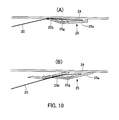
- FIG. 10 are views which illustrate bill holding members included in a paper sheet stacking device according to a second embodiment.
- FIG. 10(A) is a view which illustrates the bill holding members that are arranged on a conveyer belt so as not to overlap with one another.
- FIG. 10 (B) is a view which illustrates the bill holding members that are arranged on the conveyer belt so as to overlap with one another.
- Components in FIG. 10 which are identical or equivalent to those illustrated in FIGS. 5 and 7 are marked with the same numerals and detailed descriptions of them will be omitted.
- a bill holding member 25 used in a paper sheet stacking device realizes grip force for holding a bill 20 by the elastic force of an elastic body. That is to say, the bill holding member 25 has a base 25a whose one end is fixed onto a conveyer belt 24 and which is made from a hard material, a bill pressing portion 25b attached to the other end of the base 25a, and an elastic body which makes the bill pressing portion 25b tilt to a conveyer belt 24 side.
- the bill pressing portion 25b preferably is attached to the base 25a so that the bill pressing portion 25b can pivot.
- a coiled spring 25g is placed on an axis and makes the bill pressing portion 25b tilt to the conveyer belt 24 side.
- a range in which the bill pressing portion 25b tilts is limited so that when the bill holding member 25 receives a bill 20 from conveying rollers 26 and 27, interference will not occur between the conveying rollers 26 and 27 and the bill pressing portion 25b.
- the bill pressing portion 25b can tilt only to a position in the conveyer belt 24 indicated by a dashed line in a state in which the bill holding member 25 is not fixed onto the conveyer belt 24. This is realized, for example, by attaching a stopper portion by which a part of the bill pressing portion 25b touches the base 25a and by which the bill pressing portion 25b cannot pivot any further.
- the bill pressing portion 25b can tilt only to a position in a base 25a of an adjacent bill holding member 25 indicated by a dashed line.
- FIG. 11 are views which illustrate a modification of the bill holding member included in the paper sheet stacking device according to the second embodiment.
- FIG. 11(A) is a view which illustrates bill holding members that are arranged on the conveyer belt so as not to overlap with one another.
- FIG. 11 (B) is a view which illustrates the bill holding members that are arranged on the conveyer belt so as to overlap with one another.
- a bill holding member 25 used in the paper sheet stacking device realizes grip force for holding a bill 20 by the elastic force of a plate spring 25h. That is to say, the bill holding member 25 has a base 25a whose one end is fixed onto a conveyer belt 24 and which is made from a hard material, a bill pressing portion 25b attached to the other end of the base 25a, and the plate spring 25h which is an elastic body and which makes the bill pressing portion 25b tilt to a conveyer belt 24 side.
- the bill holding member 25 is formed by fixing both ends of the plate spring 25h, which is resin or metal, to the base 25a and the bill pressing portion 25b.
- the plate spring 25h is an insert and the bill holding member 25 is formed by insert molding. In this case, resin is poured around the plate spring 25h and is hardened. By doing so, the base 25a and the bill pressing portion 25b are formed.
- the grip force of the plate spring 25h is used for holding a bill 20 by the bill pressing portion 25b and the conveyer belt 24. Furthermore, in the case of FIG. 11(B) in which the bill holding members 25 are arranged on the conveyer belt 24 so as to overlap with one another, the grip force of the plate spring 25h is used for holding a bill 20 by the bill pressing portion 25b and a base 25a of an adjacent bill holding member 25.
- FIG. 12 is a view which illustrate a bill holding member included in a paper sheet stacking device according to a third embodiment.
- a bill holding member 25 used in a paper sheet stacking device realizes grip force for holding a bill 20 by the magnetic attraction force between magnetic attraction portions. That is to say, the bill holding member 25 has a base 25a fixed onto a conveyer belt 24, a bill pressing portion 25b which extends from the base 25a approximately parallel with the face of the conveyer belt 24 and which can swing with the base 25a as a supporting point, and a magnet 25i fixed to an end of the bill pressing portion 25b.
- a magnetic substance 25j is placed on a side of the conveyer belt 24 opposite a side on which the bill holding member 25 is fixed.
- An end of the magnetic substance 25j on a side on which a bill 20 is released extends to a position at which the bill 20 is released.
- the moving magnetic attraction portion placed in the bill holding member 25 is the magnet 25i and the fixed magnetic attraction portion placed inside the conveyer belt 24 is the magnetic substance 25j.
- the moving magnetic attraction portion and the fixed magnetic attraction portion may be a magnetic substance and a magnet, respectively, or both of the moving magnetic attraction portion and the fixed magnetic attraction portion may be magnets. If a magnet is placed inside the conveyer belt 24, the magnets are magnetized so that their faces opposite the conveyer belt 24 will have different magnetic polarities.
- many bill holding members 25 are arranged on the conveyer belt 24. However, if circumstances require, only one bill holding member 25 may be used. In this case, it is desirable to drive the rollers 22 and 23 in synchronization with the conveying rollers 26 and 27 or drive the conveying rollers 26 and 27 in synchronization with the rollers 22 and 23, according to a state in which a bill 20 is conveyed.
Landscapes
- Engineering & Computer Science (AREA)
- Mechanical Engineering (AREA)
- Pile Receivers (AREA)
- Delivering By Means Of Belts And Rollers (AREA)
Abstract
There is provided a paper sheet stacking device which can stably store, even in the case of a top bill of stacked bills being in a state different from its original state, succeeding bills.
A conveyer belt (24) is looped on rollers placed over and at both ends of a paper sheet storage part and bill holding members (25) for holding bills (20) are fixed onto an outer surface of the conveyer belt (24) at determined interval. The bill holding members (25) themselves have grip force by which the conveyer belt (24) bends inward, and hold the bills (20) by the grip force. When the bill holding members (25) pass over the roller on a reception side, their free ends (25c) get apart from the conveyer belt (24) and the bill holding members (25) receive the bills (20). When the bill holding members (25) pass between the rollers, the bill holding members (25) grip portions near ends of the bills (20). When the bill holding members (25) pass under the roller on a release side, their free ends (25c) get apart from the conveyer belt (24). The bill holding members (25) release the bills (20), make the bills (20) fall onto stacked bills, and stack and store the bills (20).
Description
- The embodiments discussed herein are related to a paper sheet stacking device and, more particularly, to a paper sheet stacking device which can stably perform stacking at the time of stacking paper media, such as bills, conveyed one by one into a bundle.
- ATMs (Automatic Teller Machines), automatic transaction apparatus, and the like installed in stores and the like of financial institutions include paper sheet stacking devices which stack and store bills conveyed one by one. A bill is conveyed in a direction parallel with faces of bills stacked in a storage part, and its end slides on a top bill of bills stacked in the storage part. As a result, the bill is introduced into the storage part. Bills are stacked in this way in these paper sheet stacking devices.
- Usually bills conveyed to a storage part have gone into various states different from their original states while they are in circulation. For example, a bill folded is creased. A bill put into a wallet is curled. A bill put into a trouser pocket is crumpled. If a bill in a state different from its original state, such as a bill in a curled state, is at the top of stacked bills, an end of a bill conveyed strikes against a rear end of the bill in a curled state and bills are not arranged properly. This interference between a bill conveyed and bills stacked is liable to occur especially in paper sheet stacking devices into which bills longitudinally conveyed are longitudinally introduced and stored.
- Some proposals for avoiding the above interference between a bill conveyed and bills stacked are known. For example, portions near rear ends of bills stacked are pressed down by a hold-down lever to ensure a bill route in a direction from which bills are conveyed (see, for example, PTL1). In this case, the hold-down lever is placed on an upstream side of a conveying roller which feeds bills into a storage part. One end of the hold-down lever is supported so that it will freely pivot. A free end of the hold-down lever touches a top bill of bills stacked in the storage part. As a result, a bill conveyed is inserted between the free end of the hold-down lever and the top bill, slides on the top bill while lifting the free end of the hold-down lever, and is stacked on the top bill.
- Furthermore, a rear end of a bill which has just been introduced into a storage part is pushed downward by a runner to ensure a bill route in a direction from which bills are conveyed (see, for example, PTL2). In this case, the runner is arranged coaxially with a conveying roller which feeds bills into the storage part. The runner pushes downward a rear end of a bill which has just been introduced into the storage part to prevent interference between the bill and an end of the following bill. Furthermore, even if a hold-down lever is also used, the runner can effectively prevent the flutter of a rear end of a bill which the hold-down lever cannot prevent.
-
- PTL1: Japanese Laid-open Patent Publication No.
2010-95365 - PTL2: Japanese Laid-open Patent Publication No.
2003-16499 - However, even if a hold-down lever or a runner is used for pressing down or pushing downward a rear end of a bill introduced, there is a possibility that a portion on an end side of a bill to which the function of the hold-down lever or the runner does not extend is in a state different from its original state. In this case, interference may still occur between a top bill and the following bill.
- The present invention was made in view of this problem. An object of the present invention is to provide a paper sheet stacking device which stably stores the following bills even in the case of a top bill of bills stacked being in a state different from its original state.
- In order to solve the above problem, there is provided a paper sheet stacking device which introduces paper sheets conveyed, which stores the paper sheets in a stacked state, and which includes a paper sheet storage part that receives and stores the paper sheets one by one, an endless conveyer belt looped on a first roller placed on a side over the paper sheet storage part on which the paper sheets are received and a second roller placed on a side over the paper sheet storage part on which the paper sheets are released, and paper sheet holding members each having one end fixed onto an outer surface of the conveyer belt and another end energized to a conveyer belt side on a downstream side in a conveyance direction of a position at which the one end is fixed.
- When the paper sheet holding member on the conveyer belt included in the above paper sheet stacking device passes over the first roller, its end portion gets apart from the conveyer belt and the paper sheet holding member receives an end of a paper sheet. When the paper sheet holding member passes between the first roller and the second roller, the paper sheet holding member holds the paper sheet by grip force. When the paper sheet holding member passes under the second roller, its end portion gets apart from the conveyer belt. The paper sheet holding member releases the paper sheet, makes the paper sheet fall onto stacked paper sheets, and stacks and stores the paper sheet. That is to say, the paper sheet is not pushed from behind into the paper sheet storage part. An end of the paper sheet is drawn in for storage. Therefore, even if a top paper sheet of stacked paper sheets is in a state different from its original state, the paper sheet is stably stored.
- With the paper sheet stacking device having the above structure, an end of a paper sheet conveyed is held by grip force of the paper sheet holding member and is drawn in. The grip force is released on a side opposite the reception side. The paper sheet is made to fall onto stacked paper sheets. Therefore, the paper sheet stacking device has the advantage of being able to stably store a paper sheet.
- In addition, with this paper sheet stacking device an end of a paper sheet is gripped and is drawn in. As a result, a paper sheet can be conveyed for a long distance, compared with a case where a paper sheet is pushed in by utilizing its rigidity. Therefore, this paper sheet stacking device is suitable for introducing and storing rectangular paper sheets longitudinally.
- The above and other objects, features and advantages of the present invention will become apparent from the following description when taken in conjunction with the accompanying drawings which illustrate preferred embodiments of the present invention by way of example.
-
- [
FIG. 1] FIG. 1 is a perspective view which illustrates the appearance of an ATM to which a paper sheet stacking device according to an embodiment is applied. - [
FIG. 2] FIG. 2 illustrates an example of the internal structure of a bill processing section of the ATM. - [
FIG. 3] FIG. 3 is a side-view which illustrates the rough structure of a paper sheet stacking device according to a first embodiment. - [
FIG. 4] FIG. 4 is a perspective view which illustrates the rough structure of the paper sheet stacking device according to the first embodiment. - [
FIG. 5] FIG. 5 are views for describing a relationship between a conveyer belt and a bill holding member of the paper sheet stacking device according to the first embodiment,FIG. 5(A) being a view for describing the shape of the bill holding member which is not yet attached to the conveyer belt,FIG. 5(B) being a view which illustrates a state of the bill holding member at operation time. - [
FIG. 6] FIG. 6 are views from a paper sheet storage part side which illustrate a state in which bill holding members are attached to the conveyer belt,FIG. 6 (A) being a view which illustrates an example of the shape of paper sheet holding members,FIG. 6(B) being a view which illustrates another example of the shape of paper sheet holding members. - [
FIG. 7] FIG. 7 are views for describing another relationship between the conveyer belt and a bill holding member of the paper sheet stacking device according to the first embodiment,FIG. 7(A) being a view for describing the shape of the bill holding member which is not yet attached to the conveyer belt,FIG. 7(B) being a view which illustrates a state of the bill holding member at operation time. - [
FIG. 8] FIG. 8 is a fragmentary sectional view which illustrates an example of the combination of the conveyer belt and the bill holding member. - [
FIG. 9] FIG. 9 is a view for describing a state in which bills are arranged on a bill release side by the bill holding members. - [
FIG. 10] FIG. 10 are views which illustrate bill holding members included in a paper sheet stacking device according to a second embodiment,FIG. 10(A) being a view which illustrates the bill holding members that are arranged on a conveyer belt so as not to overlap with one another,FIG. 10(B) being a view which illustrates the bill holding members that are arranged on the conveyer belt so as to overlap with one another. - [
FIG. 11] FIG. 11 are views which illustrate a modification of the bill holding member included in the paper sheet stacking device according to the second embodiment,FIG. 11(A) being a view which illustrates bill holding members that are arranged on the conveyer belt so as not to overlap with one another,FIG. 11(B) being a view which illustrates the bill holding members that are arranged on the conveyer belt so as to overlap with one another. - [
FIG. 12] FIG. 12 is a view which illustrates a bill holding member included in a paper sheet stacking device according to a third embodiment. - Embodiments will now be described in detail with reference to the drawings with an ATM having a mechanism for conveying and storing bills longitudinally as an example.
-
FIG. 1 is a perspective view which illustrates the appearance of an ATM to which a paper sheet stacking device according to an embodiment is applied.FIG. 2 illustrates an example of the internal structure of a bill processing section of the ATM. - As illustrated in
FIG. 1 , an ATM includes in the front acustomer operation part 1, a bill insertion and dispensingaperture 2, a coin insertion and dispensingaperture 3, a card insertion andejection aperture 4, and a bankbook insertion andejection aperture 5. Thecustomer operation part 1 is used for operation by which input or instructions regarding a cash transaction are given. Thecustomer operation part 1 includes a display portion, such as a liquid crystal panel, and a position input portion, such as a touch pad. Operation by which input is provided to the ATM is performed by touching a screen. The bill insertion and dispensingaperture 2 receives bills at the time of a transaction, such as receipt of money, and releases paid bills at the time of a transaction, such as payment of money. The coin insertion and dispensingaperture 3 receives coins at the time of a transaction, such as receipt of money, and releases coins paid as change at the time of a transaction, such as receipt of money or remittance. The card insertion andejection aperture 4 handles a cash card used for identifying an individual at the time of the operation of the ATM, a transfer card used at the time of transfer operation, and the like. The bankbook insertion andejection aperture 5 receives a bankbook and prints the contents of a transaction onto it. - As illustrated in
FIG. 2 , this ATM includes a bill processing parts. That is to say, the ATM includes the bill insertion and dispensingaperture 2 which receives and pays bills, adiscrimination part 6 which determines the kind and genuineness of bills, and atemporary pool part 7 which pools received bills after determination, for example, until the conclusion of a transaction. In addition, the ATM includes areject part 8 which stores, at the time of the determination that bills are inadequate for reuse being made, the bills as bad bills andstorage parts storage parts storage parts storage part storage parts - A paper sheet stacking device according to the present invention can be applied to a part in which bills are stacked in a bundle. For example, a paper sheet stacking device according to the present invention is applied to a part which is placed adjacently to the bill insertion and dispensing
aperture 2, which receives and stacks in order bills sent one by one from thestorage part aperture 2 in a bundle. It is a matter of course that a paper sheet stacking device according to the present invention can also be applied to thetemporary pool part 7, thereject part 8, and thestorage parts -
FIG. 3 is a side-view which illustrates the rough structure of a paper sheet stacking device according to a first embodiment.FIG. 4 is a perspective view which illustrates the rough structure of the paper sheet stacking device according to the first embodiment. - The paper sheet stacking device according to the first embodiment includes a paper
sheet storage part 21 which stacks andstores bills 20 conveyed one by one. Aroller 22 is placed on a side over the papersheet storage part 21 on which thebills 20 are received and aroller 23 is placed on an opposite side over the papersheet storage part 21 on which thebills 20 are released. Anendless conveyer belt 24 is looped on therollers bill holding members 25 which hold ends of thebills 20 conveyed are fixed onto an outer surface of theconveyer belt 24. In the examples ofFIGS. 3 and4 , a plurality ofbill holding members 25 are arranged at determined intervals in a conveyance direction on the outer surface of theconveyer belt 24 in a state in which they overlap with one another. However, thebill holding members 25 may be fixed onto theconveyer belt 24 in the conveyance direction in a state in which they do not overlap with one another, that is to say, in a state in which they are apart from one another. If thebill holding members 25 do not overlap with one another, thenFIGS. 3 and4 indicate the movement of thebill holding members 25 at the time of theconveyer belt 24 operating. - Furthermore, a pair of conveying
rollers bills 20 are received, and fulfills the function of passing to the paper sheet stackingdevice bills 20 conveyed longitudinally one by one. Thebills 20 passed to the paper sheet stacking device are conveyed in a state in which their ends are held by thebill holding members 25 of the paper sheet stacking device. Accordingly, a conveying speed of theconveyer belt 24 is equal to or slightly lower than a speed at which thebills 20 are conveyed by the conveyingrollers - The ends of the
bills 20 supplied by the conveyingrollers roller 22 side by theconveyer belt 24 and thebill holding members 25. Thebills 20 are conveyed to the opposite side of the papersheet storage part 21 in a state in which their ends are held by theconveyer belt 24 and thebill holding members 25. Thebill holding members 25 release thebills 20 on theroller 23 side. As a result, thebills 20 fall onto a top bill stored in the papersheet storage part 21 and are stacked. - If a large number of
bills 20 are stored, the papersheet storage part 21 has at the bottom a stage which freely goes up and down. Accordingly, when the number ofbills 20 stored in the papersheet storage part 21 changes, control is exercised so that the stage will go up or down. As a result, the position of atop bill 20 does not change materially. - Furthermore, in the example of
FIG. 4 , oneconveyer belt 24 onto which thebill holding members 25 are fixed is placed in order to store thebills 20 conveyed in the papersheet storage part 21. However, a plurality ofconveyer belts 24 may be arranged and used at need. -
FIG. 5 are views for describing a relationship between the conveyer belt and a bill holding member of the paper sheet stacking device according to the first embodiment.FIG. 5(A) is a view for describing the shape of the bill holding member which is not yet attached to the conveyer belt.FIG. 5(B) is a view which illustrates a state of the bill holding member at operation time. - The
bill holding member 25 has abase 25a fixed onto theconveyer belt 24 and abill pressing portion 25b which extends from thebase 25a in a direction close to a direction of conveyance by theconveyer belt 24 and which presses abill 20 against theconveyer belt 24. Thebase 25a and thebill pressing portion 25b are integrally formed from an elastic material. - As illustrated in
FIG. 5(A) , thebill holding member 25 is formed so that it will have the following shape. Afree end 25c of thebill pressing portion 25b cuts into theconveyer belt 24 by distance a beyond afitting face 25d of thebase 25a. As a result, as illustrated inFIG. 5(B) , if thebill holding member 25 is fixed onto theconveyer belt 24, thefree end 25c of thebill pressing portion 25b functions so as to bend theconveyer belt 24 to a side opposite a side on which thebill holding member 25 is fixed. This flection is grip force for holding thebill 20. -
FIG. 6 are views from a paper sheet storage part side which illustrate a state in which bill holding members are attached to the conveyer belt.FIG. 6(A) is a view which illustrates an example of the shape of paper sheet holding members.FIG. 6(B) is a view which illustrates another example of the shape of paper sheet holding members. - The
bill holding members 25 are arranged at determined intervals in the direction of conveyance by theconveyer belt 24 so that they will not overlap with one another. InFIG. 6(A) , thebill holding members 25 are arranged in a state in which abase 25a of abill holding member 25 and afree end 25c of an adjacentbill holding member 25 are apart. InFIG. 6(B) , on the other hand, a notch is cut in a central portion on abase 25a side of eachbill holding member 25 and thebill holding members 25 are arranged in a state in which afree end 25c of abill holding member 25 fits into a notch of an adjacentbill holding member 25. By shortening in this way intervals at which thebill holding members 25 are arranged in the direction of conveyance by theconveyer belt 24, the number of positions on theconveyer belt 24 at which thebill holding members 25 receivebills 20 from the conveyingrollers rollers rollers -
FIG. 7 are views for describing another relationship between the conveyer belt and a bill holding member of the paper sheet stacking device according to the first embodiment.FIG. 7 (A) is a view for describing the shape of the bill holding member which is not yet attached to the conveyer belt.FIG. 7(B) is a view which illustrates a state of the bill holding member at operation time. - Unlike the case of
FIG. 5 , thebill holding members 25 are arranged on theconveyer belt 24 in a state in which they overlap with one another. Abill holding member 25 has abase 25a fixed onto theconveyer belt 24 and abill pressing portion 25b which extends from thebase 25a in the direction of conveyance by theconveyer belt 24 and which presses abill 20 against theconveyer belt 24. In the example ofFIG. 7(A) , thebill holding member 25 has apressing protrusion 25e near afree end 25c of thebill pressing portion 25b on aconveyer belt 24 side. Thebase 25a, thebill pressing portion 25b, and thepressing protrusion 25e are integrally formed from an elastic material. - As illustrated in
FIG. 7(A) , thebill holding member 25 is formed so that it will have the following shape. Thepressing protrusion 25e protrudes by distance b from a face on a papersheet storage part 21 side of thebill pressing portion 25b to theconveyer belt 24 side. As a result, if a bill holding member 25-1 and an adjacent bill holding member 25-2 behind are fixed onto theconveyer belt 24, a state illustrated inFIG. 7(B) arises. That is to say, apressing protrusion 25e-1 of the bill holding member 25-1 is on abill pressing portion 25b-2 of the adjacent bill holding member 25-2 behind and abill pressing portion 25b-1 bends to the papersheet storage part 21 side. At this time thepressing protrusion 25e-1 of the bill holding member 25-1 touches an area c on an outer surface of thebill pressing portion 25b-2 of the adjacent bill holding member 25-2 behind by a reaction caused by the flection of thebill pressing portion 25b-1. As a result, grip force for holding thebill 20 is obtained. In addition, an inner surface of thebill pressing portion 25b-1 of the bill holding member 25-1 touches an end portion d of abase 25a-2 of the adjacent bill holding member 25-2 behind. By doing so, thebill 20 is held. Therefore, thebill 20 is fixed more firmly. -
FIG. 8 is a fragmentary sectional view which illustrates an example of the combination of the conveyer belt and the bill holding member. - A
rib 24a protruding from a surface of theconveyer belt 24 onto which thebill holding member 25 is fixed is formed. Thisrib 24a has a head portion at its end and extends in a crosswise direction of theconveyer belt 24 so as to cross theconveyer belt 24. A section of therib 24a has the shape of a mushroom. A more detailed description of therib 24a is as follows. A base 24b of therib 24a (at which therib 24a is joined to the conveyer belt 24) is narrow in the direction of conveyance by theconveyer belt 24 and anopposite end portion 24c of therib 24a is wider in the direction of conveyance by theconveyer belt 24 than the base 24b of therib 24a. On the other hand, afitting groove 25f whose section has the same shape that a section of therib 24a has is formed in thebase 25a of thebill holding member 25 so that it will extend in the crosswise direction of theconveyer belt 24. - The
bill holding member 25 is fixed onto theconveyer belt 24 by fitting therib 24a of theconveyer belt 24 into thefitting groove 25f and sliding thebill holding member 25 in the crosswise direction of theconveyer belt 24. A portion in which therib 24a is fitted into thefitting groove 25f is fixed more firmly, for example, by injecting an adhesive into clearance. Furthermore, the size of thefitting groove 25f is made approximately equal to or slightly smaller than that of therib 24a. By doing so, thebill holding member 25 is fixed firmly when therib 24a is fitted into thefitting groove 25f. In addition, a part ofbill holding members 25 which are significantly expendable can be replaced. -
FIG. 9 is a view for describing a state in which bills are arranged on a bill release side by the bill holding members. - The paper
sheet storage part 21 has, on a side on which bills 20 held and conveyed by theconveyer belt 24 and thebill holding members 25 are released, aguide 21a for catching and properly arranging the released bills 20. Abase 25a of abill holding member 25 reaches an area in which the direction of conveyance by theconveyer belt 24 is changed by the roller. 23, and abill pressing portion 25b of thebill holding member 25 gets apart from theconveyer belt 24. At this time abill 20 is released. At this point of time the force of conveyance by the conveyingrollers bill 20 falls at that position onto a stackedtop bill 20 stored in the papersheet storage part 21. After that, abill holding member 25 on a downstream side in the direction of conveyance of thebill holding member 25 which has held and conveyed thebill 20 rises from theconveyer belt 24 and moves to theguide 21a while pressing a portion near an end of the storedbill 20 with anouter surface 25k of itsbill pressing portion 25b. As thebill pressing portion 25b moves, thetop bill 20 slides on a second storedbill 20 from the top. A front edge of thetop bill 20 touches theguide 21a and stops. As a result, bills 20 are stacked and stored in the papersheet storage part 21 in an arranged state in which their front edges are touching theguide 21a. -
FIG. 10 are views which illustrate bill holding members included in a paper sheet stacking device according to a second embodiment.FIG. 10(A) is a view which illustrates the bill holding members that are arranged on a conveyer belt so as not to overlap with one another.FIG. 10 (B) is a view which illustrates the bill holding members that are arranged on the conveyer belt so as to overlap with one another. Components inFIG. 10 which are identical or equivalent to those illustrated inFIGS. 5 and7 are marked with the same numerals and detailed descriptions of them will be omitted. - A
bill holding member 25 used in a paper sheet stacking device according to a second embodiment realizes grip force for holding abill 20 by the elastic force of an elastic body. That is to say, thebill holding member 25 has abase 25a whose one end is fixed onto aconveyer belt 24 and which is made from a hard material, abill pressing portion 25b attached to the other end of thebase 25a, and an elastic body which makes thebill pressing portion 25b tilt to aconveyer belt 24 side. Thebill pressing portion 25b preferably is attached to thebase 25a so that thebill pressing portion 25b can pivot. Acoiled spring 25g is placed on an axis and makes thebill pressing portion 25b tilt to theconveyer belt 24 side. - A range in which the
bill pressing portion 25b tilts is limited so that when thebill holding member 25 receives abill 20 from conveyingrollers rollers bill pressing portion 25b. In the case ofFIG. 10(A) in which thebill holding members 25 are arranged on theconveyer belt 24 so as not to overlap with one another, thebill pressing portion 25b can tilt only to a position in theconveyer belt 24 indicated by a dashed line in a state in which thebill holding member 25 is not fixed onto theconveyer belt 24. This is realized, for example, by attaching a stopper portion by which a part of thebill pressing portion 25b touches thebase 25a and by which thebill pressing portion 25b cannot pivot any further. Furthermore, in the case ofFIG. 10(B) in which thebill holding members 25 are arranged on theconveyer belt 24 so as to overlap with one another, thebill pressing portion 25b can tilt only to a position in abase 25a of an adjacentbill holding member 25 indicated by a dashed line. -
FIG. 11 are views which illustrate a modification of the bill holding member included in the paper sheet stacking device according to the second embodiment.FIG. 11(A) is a view which illustrates bill holding members that are arranged on the conveyer belt so as not to overlap with one another.FIG. 11 (B) is a view which illustrates the bill holding members that are arranged on the conveyer belt so as to overlap with one another. - A
bill holding member 25 used in the paper sheet stacking device according to the second embodiment realizes grip force for holding abill 20 by the elastic force of aplate spring 25h. That is to say, thebill holding member 25 has abase 25a whose one end is fixed onto aconveyer belt 24 and which is made from a hard material, abill pressing portion 25b attached to the other end of thebase 25a, and theplate spring 25h which is an elastic body and which makes thebill pressing portion 25b tilt to aconveyer belt 24 side. Thebill holding member 25 is formed by fixing both ends of theplate spring 25h, which is resin or metal, to thebase 25a and thebill pressing portion 25b. For example, theplate spring 25h is an insert and thebill holding member 25 is formed by insert molding. In this case, resin is poured around theplate spring 25h and is hardened. By doing so, thebase 25a and thebill pressing portion 25b are formed. - In the case of
FIG. 11 (A) in whichbill holding members 25 are arranged on theconveyer belt 24 so as not to overlap with one another, the grip force of theplate spring 25h is used for holding abill 20 by thebill pressing portion 25b and theconveyer belt 24. Furthermore, in the case ofFIG. 11(B) in which thebill holding members 25 are arranged on theconveyer belt 24 so as to overlap with one another, the grip force of theplate spring 25h is used for holding abill 20 by thebill pressing portion 25b and abase 25a of an adjacentbill holding member 25. -
FIG. 12 is a view which illustrate a bill holding member included in a paper sheet stacking device according to a third embodiment. - A
bill holding member 25 used in a paper sheet stacking device according to a third embodiment realizes grip force for holding abill 20 by the magnetic attraction force between magnetic attraction portions. That is to say, thebill holding member 25 has abase 25a fixed onto aconveyer belt 24, abill pressing portion 25b which extends from thebase 25a approximately parallel with the face of theconveyer belt 24 and which can swing with thebase 25a as a supporting point, and amagnet 25i fixed to an end of thebill pressing portion 25b. In addition, in order to give grip force to thebill holding member 25, amagnetic substance 25j is placed on a side of theconveyer belt 24 opposite a side on which thebill holding member 25 is fixed. An end of themagnetic substance 25j on a side on which abill 20 is released extends to a position at which thebill 20 is released. As a result, when themagnet 25i of thebill holding member 25 moves in an area in which themagnetic substance 25j is placed, themagnet 25i is attracted by themagnetic substance 25j and grip force is produced. Thebill 20 is held by this grip force. Thebill 20 is released at a position at which themagnetic substance 25j ends. - In the example of
FIG. 12 , the moving magnetic attraction portion placed in thebill holding member 25 is themagnet 25i and the fixed magnetic attraction portion placed inside theconveyer belt 24 is themagnetic substance 25j. However, the moving magnetic attraction portion and the fixed magnetic attraction portion may be a magnetic substance and a magnet, respectively, or both of the moving magnetic attraction portion and the fixed magnetic attraction portion may be magnets. If a magnet is placed inside theconveyer belt 24, the magnets are magnetized so that their faces opposite theconveyer belt 24 will have different magnetic polarities. - In the above embodiments many
bill holding members 25 are arranged on theconveyer belt 24. However, if circumstances require, only onebill holding member 25 may be used. In this case, it is desirable to drive therollers rollers rollers rollers bill 20 is conveyed. - The foregoing is considered as illustrative only of the principles of the present invention. Further, since numerous modifications and changes will readily occur to those skilled in the art, it is not desired to limit the invention to the exact construction and applications shown and described, and accordingly, all suitable modifications and equivalents may be regarded as falling within the scope of the invention in the appended claims and their equivalents.
-
- 1
- customer operation part
- 2
- bill insertion and dispensing aperture
- 3
- coin insertion and dispensing aperture
- 4
- card insertion and ejection aperture
- 5
- bankbook insertion and ejection aperture
- 6
- discrimination part
- 7
- temporary pool part
- 8
- reject part
- 9, 10, 11, 12, and 13
- storage part
- 20
- bill
- 21
- paper sheet storage part
- 21a
- guide
- 22 and 23
- roller
- 24
- conveyer belt
- 24a
- rib
- 25, 25-1, and 25-2
- bill holding member
- 25a and 25a-2
- base
- 25b, 25b-1, and 25b-2
- bill pressing portion
- 25c
- free end
- 25d
- fitting face
- 25e and 25e-1
- pressing protrusion
- 25f
- fitting groove
- 25g
- coiled spring
- 25h
- plate spring
- 25i
- magnet
- 25j
- magnetic substance
- 25k
- outer surface
- 26 and 27
- conveying roller
Claims (15)
- A paper sheet stacking device which introduces paper sheets conveyed and which stores the paper sheets in a stacked state, the device comprising:a paper sheet storage part which receives and stores the paper sheets one by one;an endless conveyer belt looped on a first roller placed on a side over the paper sheet storage part on which the paper sheets are received and a second roller placed on a side over the paper sheet storage part on which the paper sheets are released; andpaper sheet holding members each having one end fixed onto an outer surface of the conveyer belt and another end energized to a conveyer belt side on a downstream side in a conveyance direction of a position at which the one end is fixed.
- The paper sheet stacking device according to claim 1, wherein:the paper sheet holding members are arranged at determined intervals in the conveyance direction of the conveyer belt so as not to overlap with one another; andthe paper sheet is held by the another end and the conveyer belt.
- The paper sheet stacking device according to claim 2, wherein:each of the paper sheet holding members is an elastic body having a shape by which the another end is, at the time of the one end being fixed onto the conveyer belt like a plane, at a position beyond the plane of the conveyer belt; andthe elastic body is bent by the conveyer belt and therefore the paper sheet is held.
- The paper sheet stacking device according to claim 2, wherein:each of the paper sheet holding members has a first portion having one end which is fixed onto the conveyer belt and which is formed from a hard material, a second portion attached to a free end of the first portion, and an elastic body which energizes the second portion so as to make the second portion tilt to the conveyer belt side; andthe second portion holds the paper sheet by energizing force of the elastic body.
- The paper sheet stacking device according to claim 4, wherein the elastic body is a coiled spring placed on an axis at which the second portion is attached to the first portion so as to freely pivot.
- The paper sheet stacking device according to claim 4, wherein the elastic body is a plate spring whose both ends are fixed to the first portion and the second portion.
- The paper sheet stacking device according to claim 2, wherein:each of the paper sheet holding members has a swinging portion which extends approximately parallel with a face of the conveyer belt and which can swing with the one end fixed onto the conveyer belt as a supporting point and a first magnetic attraction portion attached to a free end of the swinging portion; andthe paper sheet is held by attraction force produced between the first magnetic attraction portion and a second magnetic attraction portion placed in a lower conveyance area inside the conveyer belt.
- The paper sheet stacking device according to claim 7, wherein one of the first magnetic attraction portion and the second magnetic attraction portion is a magnet and another is a magnet or a magnetic substance.
- The paper sheet stacking device according to claim 1, wherein:the paper sheet holding members are arranged at determined intervals in the conveyance direction of the conveyer belt so as to overlap with one another; andthe paper sheet is held by the another end and an adjacent paper sheet holding member on an upstream side in the conveyance direction.
- The paper sheet stacking device according to claim 9, wherein:each of the paper sheet holding members is an elastic body having a shape by which the another end is, at the time of the one end being fixed onto the conveyer belt like a plane, at a position on the conveyer belt side beyond a face on the paper sheet storage part side of the adjacent paper sheet holding member on a downstream side in the conveyance direction; andthe another end is on the adjacent paper sheet holding member, the elastic body bends, and therefore the paper sheet is held.
- The paper sheet stacking device according to claim 9, wherein:each of the paper sheet holding members has a first portion having one end which is fixed onto the conveyer belt and which is formed from a hard material, a second portion attached to a free end of the first portion, and an elastic body which energizes the second portion so as to make the second portion tilt to the conveyer belt side; andthe second portion which is on the first portion of an adjacent paper sheet holding member on a downstream side in the conveyance direction holds the paper sheet by energizing force of the elastic body.
- The paper sheet stacking device according to claim 11, wherein the elastic body is a coiled spring placed on an axis at which the second portion is attached to the first portion so as to freely pivot.
- The paper sheet stacking device according to claim 11, wherein the elastic body is a plate spring whose both ends are fixed to the first portion and the second portion.
- The paper sheet stacking device according to claim 2 or 9, wherein each of the paper sheet holding members is fixed onto the conveyer belt by fitting a rib protruding from a face of the conveyer belt onto which each of the paper sheet holding members is fixed into a fitting groove which is formed on one end side of each of the paper sheet holding members and whose section is equal in shape to a section of the rib.
- The paper sheet stacking device according to claim 1, wherein:the paper sheet holding members are arranged at determined intervals in the conveyance direction of the conveyer belt so as to overlap with one another;a notch is cut in the one end of each of the paper sheet holding members fixed onto the outer surface of the conveyer belt; andthe paper sheet holding members are arranged in a state in which the another end of each adjacent paper sheet holding member on an upstream side in the conveyance direction fits into the notch.
Applications Claiming Priority (1)
| Application Number | Priority Date | Filing Date | Title |
|---|---|---|---|
| PCT/JP2011/076786 WO2013076787A1 (en) | 2011-11-21 | 2011-11-21 | Paper aggregation device |
Publications (2)
| Publication Number | Publication Date |
|---|---|
| EP2784012A1 true EP2784012A1 (en) | 2014-10-01 |
| EP2784012A4 EP2784012A4 (en) | 2017-07-26 |
Family
ID=48469269
Family Applications (1)
| Application Number | Title | Priority Date | Filing Date |
|---|---|---|---|
| EP11876223.6A Withdrawn EP2784012A4 (en) | 2011-11-21 | 2011-11-21 | Paper aggregation device |
Country Status (6)
| Country | Link |
|---|---|
| US (1) | US20140203500A1 (en) |
| EP (1) | EP2784012A4 (en) |
| CN (1) | CN103874643B (en) |
| BR (1) | BR112014008986A2 (en) |
| MX (1) | MX2014004546A (en) |
| WO (1) | WO2013076787A1 (en) |
Families Citing this family (2)
| Publication number | Priority date | Publication date | Assignee | Title |
|---|---|---|---|---|
| US11479433B2 (en) * | 2018-10-30 | 2022-10-25 | Ricoh Company, Ltd. | Sheet conveying device and image forming apparatus incorporating the sheet conveying device |
| CN120032450A (en) * | 2023-11-23 | 2025-05-23 | 山东新北洋信息技术股份有限公司 | Banknote accumulation device, cash circulation processing equipment and banknote accumulation control method |
Family Cites Families (19)
| Publication number | Priority date | Publication date | Assignee | Title |
|---|---|---|---|---|
| US4203590A (en) * | 1978-01-09 | 1980-05-20 | Levi Strauss & Co. | Gripper belt transfer |
| JPS5561553A (en) * | 1978-11-01 | 1980-05-09 | Ricoh Co Ltd | Paper feeding apparatus |
| JPS5693651A (en) * | 1979-12-27 | 1981-07-29 | Tokyo Electric Co Ltd | Containing device for sheet object |
| JPS6238257U (en) * | 1985-08-27 | 1987-03-06 | ||
| JPS6244852U (en) * | 1985-09-03 | 1987-03-18 | ||
| JPH02129356U (en) * | 1989-03-31 | 1990-10-25 | ||
| JPH034158U (en) * | 1989-05-31 | 1991-01-16 | ||
| DE19901698B4 (en) * | 1998-02-11 | 2008-01-24 | Heidelberger Druckmaschinen Ag | Device for transporting sheets or folded products |
| DE19916668B4 (en) * | 1999-04-14 | 2010-06-24 | Michael Hörauf Maschinenfabrik GmbH & Co. KG | Device for transporting flat blanks |
| JP2003016499A (en) | 2001-07-04 | 2003-01-17 | Toyo Commun Equip Co Ltd | Bill storage device |
| DE10147134B4 (en) * | 2001-09-25 | 2008-06-19 | Wincor Nixdorf International Gmbh | Stacking straps with switched deposit cassettes |
| DE10348233A1 (en) * | 2003-10-09 | 2005-05-04 | Optima Filling & Packaging | Apparatus for forming stacks |
| JP4265544B2 (en) * | 2005-01-28 | 2009-05-20 | 沖電気工業株式会社 | Impeller |
| JP2008133106A (en) * | 2006-11-29 | 2008-06-12 | Nisca Corp | Sheet stacking device and image forming system equipped therewith |
| EP2130654B1 (en) * | 2008-06-05 | 2012-08-01 | Müller Martini Holding AG | Device for cutting the header and footer of printed products fed through a cutter |
| JP5390164B2 (en) | 2008-10-17 | 2014-01-15 | 富士通フロンテック株式会社 | Paper sheet discharge and accumulation device |
| JP4891385B2 (en) * | 2008-12-26 | 2012-03-07 | キヤノン株式会社 | Sheet stacking apparatus and image forming apparatus |
| EP2223878B1 (en) * | 2009-02-27 | 2013-11-20 | Neopost Technologies | Conveyor chain and conveyor for gripping and conveying paper material |
| EP2623447A1 (en) * | 2012-01-31 | 2013-08-07 | Neopost Technologies | Item collating system and method |
-
2011
- 2011-11-21 MX MX2014004546A patent/MX2014004546A/en not_active Application Discontinuation
- 2011-11-21 BR BR112014008986A patent/BR112014008986A2/en not_active IP Right Cessation
- 2011-11-21 EP EP11876223.6A patent/EP2784012A4/en not_active Withdrawn
- 2011-11-21 CN CN201180074061.7A patent/CN103874643B/en not_active Expired - Fee Related
- 2011-11-21 WO PCT/JP2011/076786 patent/WO2013076787A1/en not_active Ceased
-
2014
- 2014-03-25 US US14/224,500 patent/US20140203500A1/en not_active Abandoned
Non-Patent Citations (1)
| Title |
|---|
| See references of WO2013076787A1 * |
Also Published As
| Publication number | Publication date |
|---|---|
| US20140203500A1 (en) | 2014-07-24 |
| WO2013076787A1 (en) | 2013-05-30 |
| CN103874643B (en) | 2016-02-10 |
| MX2014004546A (en) | 2014-08-01 |
| BR112014008986A2 (en) | 2017-05-02 |
| EP2784012A4 (en) | 2017-07-26 |
| CN103874643A (en) | 2014-06-18 |
Similar Documents
| Publication | Publication Date | Title |
|---|---|---|
| RU2638133C2 (en) | Device for media protection and device for separating and placing media | |
| RU2637897C1 (en) | Device for laying carriers and device of transactions with carriers | |
| JP6052059B2 (en) | Medium stacking apparatus and medium processing apparatus | |
| JP6721296B2 (en) | Medium guiding member and paper handling device | |
| JP5932447B2 (en) | Banknote processing apparatus and automatic transaction apparatus | |
| EP2784012A1 (en) | Paper aggregation device | |
| EP3165484B1 (en) | Media deskew | |
| CN105122321B (en) | Media storage device and medium transaction device | |
| JP2013239075A (en) | Medium accumulation apparatus and medium processing apparatus | |
| KR970006031B1 (en) | Cash dispenser of the type transporting a slip and bills together | |
| CN107531438A (en) | Media storage device and media transaction device | |
| JP5458878B2 (en) | Medium storage structure | |
| JP5791464B2 (en) | Banknote holding and separating mechanism and reflux-type banknote processing apparatus using the same | |
| JP5471693B2 (en) | Coin deposit and withdrawal machine | |
| JP4049476B2 (en) | Paper sheet transport device | |
| JP6060806B2 (en) | Medium storage apparatus and medium transaction apparatus | |
| EP2600321A1 (en) | Item stacking | |
| JPWO2013076787A1 (en) | Paper sheet stacking device | |
| JP6036147B2 (en) | Medium storage device | |
| JP5712876B2 (en) | Medium accumulation apparatus and medium transaction apparatus | |
| KR101750932B1 (en) | Apparatus for storing bill | |
| JP2008046804A (en) | Paper sheet rearrangement device | |
| JP2001063841A (en) | Paper transport device | |
| JP2007164777A (en) | Apparatus for separately storing printing paper sheets | |
| KR20070072247A (en) | Withdrawal device of automatic teller machine |
Legal Events
| Date | Code | Title | Description |
|---|---|---|---|
| PUAI | Public reference made under article 153(3) epc to a published international application that has entered the european phase |
Free format text: ORIGINAL CODE: 0009012 |
|
| 17P | Request for examination filed |
Effective date: 20140409 |
|
| AK | Designated contracting states |
Kind code of ref document: A1 Designated state(s): AL AT BE BG CH CY CZ DE DK EE ES FI FR GB GR HR HU IE IS IT LI LT LU LV MC MK MT NL NO PL PT RO RS SE SI SK SM TR |
|
| DAX | Request for extension of the european patent (deleted) | ||
| RA4 | Supplementary search report drawn up and despatched (corrected) |
Effective date: 20170628 |
|
| RIC1 | Information provided on ipc code assigned before grant |
Ipc: B65H 29/04 20060101AFI20170622BHEP |
|
| STAA | Information on the status of an ep patent application or granted ep patent |
Free format text: STATUS: THE APPLICATION IS DEEMED TO BE WITHDRAWN |
|
| 18D | Application deemed to be withdrawn |
Effective date: 20180125 |