EP2783996A1 - Sleeve pack assembly with latching mechanism - Google Patents
Sleeve pack assembly with latching mechanism Download PDFInfo
- Publication number
- EP2783996A1 EP2783996A1 EP14150885.3A EP14150885A EP2783996A1 EP 2783996 A1 EP2783996 A1 EP 2783996A1 EP 14150885 A EP14150885 A EP 14150885A EP 2783996 A1 EP2783996 A1 EP 2783996A1
- Authority
- EP
- European Patent Office
- Prior art keywords
- sleeve
- assembly
- prong
- pallet
- aperture
- Prior art date
- Legal status (The legal status is an assumption and is not a legal conclusion. Google has not performed a legal analysis and makes no representation as to the accuracy of the status listed.)
- Granted
Links
Images




Classifications
-
- B—PERFORMING OPERATIONS; TRANSPORTING
- B65—CONVEYING; PACKING; STORING; HANDLING THIN OR FILAMENTARY MATERIAL
- B65D—CONTAINERS FOR STORAGE OR TRANSPORT OF ARTICLES OR MATERIALS, e.g. BAGS, BARRELS, BOTTLES, BOXES, CANS, CARTONS, CRATES, DRUMS, JARS, TANKS, HOPPERS, FORWARDING CONTAINERS; ACCESSORIES, CLOSURES, OR FITTINGS THEREFOR; PACKAGING ELEMENTS; PACKAGES
- B65D19/00—Pallets or like platforms, with or without side walls, for supporting loads to be lifted or lowered
- B65D19/02—Rigid pallets with side walls, e.g. box pallets
- B65D19/06—Rigid pallets with side walls, e.g. box pallets with bodies formed by uniting or interconnecting two or more components
-
- B—PERFORMING OPERATIONS; TRANSPORTING
- B65—CONVEYING; PACKING; STORING; HANDLING THIN OR FILAMENTARY MATERIAL
- B65D—CONTAINERS FOR STORAGE OR TRANSPORT OF ARTICLES OR MATERIALS, e.g. BAGS, BARRELS, BOTTLES, BOXES, CANS, CARTONS, CRATES, DRUMS, JARS, TANKS, HOPPERS, FORWARDING CONTAINERS; ACCESSORIES, CLOSURES, OR FITTINGS THEREFOR; PACKAGING ELEMENTS; PACKAGES
- B65D19/00—Pallets or like platforms, with or without side walls, for supporting loads to be lifted or lowered
- B65D19/38—Details or accessories
- B65D19/385—Frames, corner posts or pallet converters, e.g. for facilitating stacking of charged pallets
-
- B—PERFORMING OPERATIONS; TRANSPORTING
- B65—CONVEYING; PACKING; STORING; HANDLING THIN OR FILAMENTARY MATERIAL
- B65D—CONTAINERS FOR STORAGE OR TRANSPORT OF ARTICLES OR MATERIALS, e.g. BAGS, BARRELS, BOTTLES, BOXES, CANS, CARTONS, CRATES, DRUMS, JARS, TANKS, HOPPERS, FORWARDING CONTAINERS; ACCESSORIES, CLOSURES, OR FITTINGS THEREFOR; PACKAGING ELEMENTS; PACKAGES
- B65D19/00—Pallets or like platforms, with or without side walls, for supporting loads to be lifted or lowered
- B65D19/02—Rigid pallets with side walls, e.g. box pallets
- B65D19/04—Rigid pallets with side walls, e.g. box pallets with bodies moulded or otherwise fabricated in one piece
-
- B—PERFORMING OPERATIONS; TRANSPORTING
- B65—CONVEYING; PACKING; STORING; HANDLING THIN OR FILAMENTARY MATERIAL
- B65D—CONTAINERS FOR STORAGE OR TRANSPORT OF ARTICLES OR MATERIALS, e.g. BAGS, BARRELS, BOTTLES, BOXES, CANS, CARTONS, CRATES, DRUMS, JARS, TANKS, HOPPERS, FORWARDING CONTAINERS; ACCESSORIES, CLOSURES, OR FITTINGS THEREFOR; PACKAGING ELEMENTS; PACKAGES
- B65D21/00—Nestable, stackable or joinable containers; Containers of variable capacity
- B65D21/08—Containers of variable capacity
- B65D21/086—Collapsible or telescopic containers
-
- B—PERFORMING OPERATIONS; TRANSPORTING
- B65—CONVEYING; PACKING; STORING; HANDLING THIN OR FILAMENTARY MATERIAL
- B65D—CONTAINERS FOR STORAGE OR TRANSPORT OF ARTICLES OR MATERIALS, e.g. BAGS, BARRELS, BOTTLES, BOXES, CANS, CARTONS, CRATES, DRUMS, JARS, TANKS, HOPPERS, FORWARDING CONTAINERS; ACCESSORIES, CLOSURES, OR FITTINGS THEREFOR; PACKAGING ELEMENTS; PACKAGES
- B65D2519/00—Pallets or like platforms, with or without side walls, for supporting loads to be lifted or lowered
- B65D2519/00004—Details relating to pallets
- B65D2519/00009—Materials
- B65D2519/00014—Materials for the load supporting surface
- B65D2519/00034—Plastic
-
- B—PERFORMING OPERATIONS; TRANSPORTING
- B65—CONVEYING; PACKING; STORING; HANDLING THIN OR FILAMENTARY MATERIAL
- B65D—CONTAINERS FOR STORAGE OR TRANSPORT OF ARTICLES OR MATERIALS, e.g. BAGS, BARRELS, BOTTLES, BOXES, CANS, CARTONS, CRATES, DRUMS, JARS, TANKS, HOPPERS, FORWARDING CONTAINERS; ACCESSORIES, CLOSURES, OR FITTINGS THEREFOR; PACKAGING ELEMENTS; PACKAGES
- B65D2519/00—Pallets or like platforms, with or without side walls, for supporting loads to be lifted or lowered
- B65D2519/00004—Details relating to pallets
- B65D2519/00009—Materials
- B65D2519/00049—Materials for the base surface
- B65D2519/00069—Plastic
-
- B—PERFORMING OPERATIONS; TRANSPORTING
- B65—CONVEYING; PACKING; STORING; HANDLING THIN OR FILAMENTARY MATERIAL
- B65D—CONTAINERS FOR STORAGE OR TRANSPORT OF ARTICLES OR MATERIALS, e.g. BAGS, BARRELS, BOTTLES, BOXES, CANS, CARTONS, CRATES, DRUMS, JARS, TANKS, HOPPERS, FORWARDING CONTAINERS; ACCESSORIES, CLOSURES, OR FITTINGS THEREFOR; PACKAGING ELEMENTS; PACKAGES
- B65D2519/00—Pallets or like platforms, with or without side walls, for supporting loads to be lifted or lowered
- B65D2519/00004—Details relating to pallets
- B65D2519/00258—Overall construction
- B65D2519/00263—Overall construction of the pallet
- B65D2519/00273—Overall construction of the pallet made of more than one piece
-
- B—PERFORMING OPERATIONS; TRANSPORTING
- B65—CONVEYING; PACKING; STORING; HANDLING THIN OR FILAMENTARY MATERIAL
- B65D—CONTAINERS FOR STORAGE OR TRANSPORT OF ARTICLES OR MATERIALS, e.g. BAGS, BARRELS, BOTTLES, BOXES, CANS, CARTONS, CRATES, DRUMS, JARS, TANKS, HOPPERS, FORWARDING CONTAINERS; ACCESSORIES, CLOSURES, OR FITTINGS THEREFOR; PACKAGING ELEMENTS; PACKAGES
- B65D2519/00—Pallets or like platforms, with or without side walls, for supporting loads to be lifted or lowered
- B65D2519/00004—Details relating to pallets
- B65D2519/00258—Overall construction
- B65D2519/00283—Overall construction of the load supporting surface
- B65D2519/00288—Overall construction of the load supporting surface made of one piece
-
- B—PERFORMING OPERATIONS; TRANSPORTING
- B65—CONVEYING; PACKING; STORING; HANDLING THIN OR FILAMENTARY MATERIAL
- B65D—CONTAINERS FOR STORAGE OR TRANSPORT OF ARTICLES OR MATERIALS, e.g. BAGS, BARRELS, BOTTLES, BOXES, CANS, CARTONS, CRATES, DRUMS, JARS, TANKS, HOPPERS, FORWARDING CONTAINERS; ACCESSORIES, CLOSURES, OR FITTINGS THEREFOR; PACKAGING ELEMENTS; PACKAGES
- B65D2519/00—Pallets or like platforms, with or without side walls, for supporting loads to be lifted or lowered
- B65D2519/00004—Details relating to pallets
- B65D2519/00258—Overall construction
- B65D2519/00283—Overall construction of the load supporting surface
- B65D2519/00293—Overall construction of the load supporting surface made of more than one piece
-
- B—PERFORMING OPERATIONS; TRANSPORTING
- B65—CONVEYING; PACKING; STORING; HANDLING THIN OR FILAMENTARY MATERIAL
- B65D—CONTAINERS FOR STORAGE OR TRANSPORT OF ARTICLES OR MATERIALS, e.g. BAGS, BARRELS, BOTTLES, BOXES, CANS, CARTONS, CRATES, DRUMS, JARS, TANKS, HOPPERS, FORWARDING CONTAINERS; ACCESSORIES, CLOSURES, OR FITTINGS THEREFOR; PACKAGING ELEMENTS; PACKAGES
- B65D2519/00—Pallets or like platforms, with or without side walls, for supporting loads to be lifted or lowered
- B65D2519/00004—Details relating to pallets
- B65D2519/00258—Overall construction
- B65D2519/00313—Overall construction of the base surface
- B65D2519/00318—Overall construction of the base surface made of one piece
-
- B—PERFORMING OPERATIONS; TRANSPORTING
- B65—CONVEYING; PACKING; STORING; HANDLING THIN OR FILAMENTARY MATERIAL
- B65D—CONTAINERS FOR STORAGE OR TRANSPORT OF ARTICLES OR MATERIALS, e.g. BAGS, BARRELS, BOTTLES, BOXES, CANS, CARTONS, CRATES, DRUMS, JARS, TANKS, HOPPERS, FORWARDING CONTAINERS; ACCESSORIES, CLOSURES, OR FITTINGS THEREFOR; PACKAGING ELEMENTS; PACKAGES
- B65D2519/00—Pallets or like platforms, with or without side walls, for supporting loads to be lifted or lowered
- B65D2519/00004—Details relating to pallets
- B65D2519/00258—Overall construction
- B65D2519/00313—Overall construction of the base surface
- B65D2519/00328—Overall construction of the base surface shape of the contact surface of the base
- B65D2519/00338—Overall construction of the base surface shape of the contact surface of the base contact surface having a discrete foot-like shape
-
- B—PERFORMING OPERATIONS; TRANSPORTING
- B65—CONVEYING; PACKING; STORING; HANDLING THIN OR FILAMENTARY MATERIAL
- B65D—CONTAINERS FOR STORAGE OR TRANSPORT OF ARTICLES OR MATERIALS, e.g. BAGS, BARRELS, BOTTLES, BOXES, CANS, CARTONS, CRATES, DRUMS, JARS, TANKS, HOPPERS, FORWARDING CONTAINERS; ACCESSORIES, CLOSURES, OR FITTINGS THEREFOR; PACKAGING ELEMENTS; PACKAGES
- B65D2519/00—Pallets or like platforms, with or without side walls, for supporting loads to be lifted or lowered
- B65D2519/00004—Details relating to pallets
- B65D2519/00258—Overall construction
- B65D2519/00398—Overall construction reinforcements
- B65D2519/00402—Integral, e.g. ribs
- B65D2519/00407—Integral, e.g. ribs on the load supporting surface
-
- B—PERFORMING OPERATIONS; TRANSPORTING
- B65—CONVEYING; PACKING; STORING; HANDLING THIN OR FILAMENTARY MATERIAL
- B65D—CONTAINERS FOR STORAGE OR TRANSPORT OF ARTICLES OR MATERIALS, e.g. BAGS, BARRELS, BOTTLES, BOXES, CANS, CARTONS, CRATES, DRUMS, JARS, TANKS, HOPPERS, FORWARDING CONTAINERS; ACCESSORIES, CLOSURES, OR FITTINGS THEREFOR; PACKAGING ELEMENTS; PACKAGES
- B65D2519/00—Pallets or like platforms, with or without side walls, for supporting loads to be lifted or lowered
- B65D2519/00004—Details relating to pallets
- B65D2519/00258—Overall construction
- B65D2519/00492—Overall construction of the side walls
- B65D2519/00497—Overall construction of the side walls whereby at least one side wall is made of one piece
-
- B—PERFORMING OPERATIONS; TRANSPORTING
- B65—CONVEYING; PACKING; STORING; HANDLING THIN OR FILAMENTARY MATERIAL
- B65D—CONTAINERS FOR STORAGE OR TRANSPORT OF ARTICLES OR MATERIALS, e.g. BAGS, BARRELS, BOTTLES, BOXES, CANS, CARTONS, CRATES, DRUMS, JARS, TANKS, HOPPERS, FORWARDING CONTAINERS; ACCESSORIES, CLOSURES, OR FITTINGS THEREFOR; PACKAGING ELEMENTS; PACKAGES
- B65D2519/00—Pallets or like platforms, with or without side walls, for supporting loads to be lifted or lowered
- B65D2519/00004—Details relating to pallets
- B65D2519/00258—Overall construction
- B65D2519/00492—Overall construction of the side walls
- B65D2519/00502—Overall construction of the side walls whereby at least one side wall is made of two or more pieces
-
- B—PERFORMING OPERATIONS; TRANSPORTING
- B65—CONVEYING; PACKING; STORING; HANDLING THIN OR FILAMENTARY MATERIAL
- B65D—CONTAINERS FOR STORAGE OR TRANSPORT OF ARTICLES OR MATERIALS, e.g. BAGS, BARRELS, BOTTLES, BOXES, CANS, CARTONS, CRATES, DRUMS, JARS, TANKS, HOPPERS, FORWARDING CONTAINERS; ACCESSORIES, CLOSURES, OR FITTINGS THEREFOR; PACKAGING ELEMENTS; PACKAGES
- B65D2519/00—Pallets or like platforms, with or without side walls, for supporting loads to be lifted or lowered
- B65D2519/00004—Details relating to pallets
- B65D2519/00547—Connections
- B65D2519/00577—Connections structures connecting side walls, including corner posts, to each other
- B65D2519/00582—Connections structures connecting side walls, including corner posts, to each other structures intended to be disassembled, i.e. collapsible or dismountable
- B65D2519/00587—Connections structures connecting side walls, including corner posts, to each other structures intended to be disassembled, i.e. collapsible or dismountable side walls directly connected to each other
- B65D2519/00592—Connections structures connecting side walls, including corner posts, to each other structures intended to be disassembled, i.e. collapsible or dismountable side walls directly connected to each other by means of hinges
-
- B—PERFORMING OPERATIONS; TRANSPORTING
- B65—CONVEYING; PACKING; STORING; HANDLING THIN OR FILAMENTARY MATERIAL
- B65D—CONTAINERS FOR STORAGE OR TRANSPORT OF ARTICLES OR MATERIALS, e.g. BAGS, BARRELS, BOTTLES, BOXES, CANS, CARTONS, CRATES, DRUMS, JARS, TANKS, HOPPERS, FORWARDING CONTAINERS; ACCESSORIES, CLOSURES, OR FITTINGS THEREFOR; PACKAGING ELEMENTS; PACKAGES
- B65D2519/00—Pallets or like platforms, with or without side walls, for supporting loads to be lifted or lowered
- B65D2519/00004—Details relating to pallets
- B65D2519/00547—Connections
- B65D2519/00577—Connections structures connecting side walls, including corner posts, to each other
- B65D2519/00582—Connections structures connecting side walls, including corner posts, to each other structures intended to be disassembled, i.e. collapsible or dismountable
- B65D2519/00587—Connections structures connecting side walls, including corner posts, to each other structures intended to be disassembled, i.e. collapsible or dismountable side walls directly connected to each other
- B65D2519/00592—Connections structures connecting side walls, including corner posts, to each other structures intended to be disassembled, i.e. collapsible or dismountable side walls directly connected to each other by means of hinges
- B65D2519/00597—Connections structures connecting side walls, including corner posts, to each other structures intended to be disassembled, i.e. collapsible or dismountable side walls directly connected to each other by means of hinges integrally formed
-
- B—PERFORMING OPERATIONS; TRANSPORTING
- B65—CONVEYING; PACKING; STORING; HANDLING THIN OR FILAMENTARY MATERIAL
- B65D—CONTAINERS FOR STORAGE OR TRANSPORT OF ARTICLES OR MATERIALS, e.g. BAGS, BARRELS, BOTTLES, BOXES, CANS, CARTONS, CRATES, DRUMS, JARS, TANKS, HOPPERS, FORWARDING CONTAINERS; ACCESSORIES, CLOSURES, OR FITTINGS THEREFOR; PACKAGING ELEMENTS; PACKAGES
- B65D2519/00—Pallets or like platforms, with or without side walls, for supporting loads to be lifted or lowered
- B65D2519/00004—Details relating to pallets
- B65D2519/00547—Connections
- B65D2519/00636—Connections structures connecting side walls to the pallet
- B65D2519/00641—Structures intended to be disassembled
- B65D2519/00661—Structures intended to be disassembled side walls maintained connected to pallet by means of auxiliary locking elements, e.g. spring loaded locking pins
-
- B—PERFORMING OPERATIONS; TRANSPORTING
- B65—CONVEYING; PACKING; STORING; HANDLING THIN OR FILAMENTARY MATERIAL
- B65D—CONTAINERS FOR STORAGE OR TRANSPORT OF ARTICLES OR MATERIALS, e.g. BAGS, BARRELS, BOTTLES, BOXES, CANS, CARTONS, CRATES, DRUMS, JARS, TANKS, HOPPERS, FORWARDING CONTAINERS; ACCESSORIES, CLOSURES, OR FITTINGS THEREFOR; PACKAGING ELEMENTS; PACKAGES
- B65D2519/00—Pallets or like platforms, with or without side walls, for supporting loads to be lifted or lowered
- B65D2519/00004—Details relating to pallets
- B65D2519/00547—Connections
- B65D2519/00706—Connections structures connecting the lid or cover to the side walls or corner posts
- B65D2519/00711—Connections structures connecting the lid or cover to the side walls or corner posts removable lid or covers
-
- B—PERFORMING OPERATIONS; TRANSPORTING
- B65—CONVEYING; PACKING; STORING; HANDLING THIN OR FILAMENTARY MATERIAL
- B65D—CONTAINERS FOR STORAGE OR TRANSPORT OF ARTICLES OR MATERIALS, e.g. BAGS, BARRELS, BOTTLES, BOXES, CANS, CARTONS, CRATES, DRUMS, JARS, TANKS, HOPPERS, FORWARDING CONTAINERS; ACCESSORIES, CLOSURES, OR FITTINGS THEREFOR; PACKAGING ELEMENTS; PACKAGES
- B65D2519/00—Pallets or like platforms, with or without side walls, for supporting loads to be lifted or lowered
- B65D2519/00004—Details relating to pallets
- B65D2519/00736—Details
- B65D2519/00865—Collapsible, i.e. at least two constitutive elements remaining hingedly connected
- B65D2519/00875—Collapsible, i.e. at least two constitutive elements remaining hingedly connected collapsible side walls
- B65D2519/0091—Collapsible, i.e. at least two constitutive elements remaining hingedly connected collapsible side walls whereby all side walls are hingedly connected to each other
-
- B—PERFORMING OPERATIONS; TRANSPORTING
- B65—CONVEYING; PACKING; STORING; HANDLING THIN OR FILAMENTARY MATERIAL
- B65D—CONTAINERS FOR STORAGE OR TRANSPORT OF ARTICLES OR MATERIALS, e.g. BAGS, BARRELS, BOTTLES, BOXES, CANS, CARTONS, CRATES, DRUMS, JARS, TANKS, HOPPERS, FORWARDING CONTAINERS; ACCESSORIES, CLOSURES, OR FITTINGS THEREFOR; PACKAGING ELEMENTS; PACKAGES
- B65D2519/00—Pallets or like platforms, with or without side walls, for supporting loads to be lifted or lowered
- B65D2519/00004—Details relating to pallets
- B65D2519/00736—Details
- B65D2519/00935—Details with special means for nesting or stacking
- B65D2519/00955—Details with special means for nesting or stacking stackable
- B65D2519/00965—Details with special means for nesting or stacking stackable when loaded
- B65D2519/00975—Details with special means for nesting or stacking stackable when loaded through the side walls
Definitions
- the present invention generally relates to a latching mechanism having a forward facing engagement panel for use with a sleeve pack assembly, and more particularly to a latching mechanism for a sleeve pack assembly having an engagement panel that can be operated by a user's foot.
- a sleeve pack includes a pallet, a sleeve and a top cap.
- the passive interference fit lock generally creates a weak engagement and/or is difficult to assemble, and can damage the sleeve.
- the active latching mechanisms available today require the operator to bend over or kneel and reach under the pallet to engage the lock.
- the present invention provides the desirable aspects of both designs, allowing for an easy passive latch assembly without the need to bend and reach, while providing a strong "lock” between the components. It also provides for active disengaging without the need to bend and reach.
- the present invention provides a spring loaded latching mechanism incorporated into a sleeve pack assembly.
- the latching mechanism is automatically engaged during set-up of the assembly (without requiring additional steps from the operator).
- the latching mechanism can be easily disengaged with a push or kick of the foot of the operator and does not require the operator to bend, kneel or reach for the mechanism.
- the latching mechanism can be formed as a one piece, plastic spring which is particularly useful for instances requiring food safety.
- Other embodiments can be formed of multiple components and can include other materials, such as a steel spring.
- the latching mechanism can be implemented on any type of sleeve pack regardless of the number of sides in the sleeve.
- the latching mechanism can be used for a sleeve pack with a sleeve having three sides, or for one having four or more sides such as an octagon shaped sleeve with eight sides.
- the latching mechanism could be implemented with a sleeve sidewall having curvature, such as a cylindrical shaped sleeve with a circular cross-section.
- a sleeve pack assembly is provided with a latching mechanism that can be operated by a user in an upright position.
- the sleeve pack assembly comprises a sleeve having a first side, a second side, and a third side. Additionally, the sleeve can include a fourth side for a rectangular shape, or have more than four sides (such as an octagon shaped sleeve with eight sides).
- the sleeve is configured to have a first bottom opening and a second top opening when opened. When not in use, the sleeve can be folded and/or collapsed to provide for more efficient transport. At least one of the sides has a first aperture proximate a bottom portion of the at least one side.
- the assembly also includes a pallet having a plurality of feet forming a base of the assembly.
- the pallet includes a channel proximate a periphery for receiving a bottom edge portion of each side of the sleeve.
- the assembly also includes a latch mechanism having a spring element and a first prong coupled to the first spring element.
- the first prong is aligned with the first aperture of the sleeve such that the first prong extends through the first aperture when the sleeve is positioned in the channel.
- the latch mechanism also includes an engagement panel positioned on an outer surface of one of the plurality of feet, such as a center foot. Activation of the engagement panel (e.g., by an operator's foot) pushes back the spring element and the first prong, and disengages the first prong from the first aperture.
- the assembly can be configured so that the sleeve includes a second aperture proximate the bottom portion of the at least one side spaced from the first aperture, and the latch mechanism includes a second prong aligned with the second aperture of the sleeve.
- the second prong is positioned to extend through the second aperture when the sleeve is positioned in the channel.
- the first prong can include an inclined upper surface. This acts as a camming surface and moves the prong out of the way when installing the sleeve into the channel.
- the second prong can have an inclined upper surface.
- the foot housing the latch mechanism can include a first window aligned with the first prong (and a second window aligned with the second prong) to allow for visual inspection of the mechanism. This enables an operator to determine that the sleeve is secured to the pallet.
- the latch mechanism can be formed as a single plastic piece.
- the latch mechanism can include a plurality of components.
- the latch mechanism can include a steel spring element.
- the assembly can also include a top cap.
- the top cap can be configured to include a latch mechanism.
- the assembly can also include a first stop for preventing inward movement of the engagement panel past a set point. Similarly, the assembly can also include a second stop.
- the stops can include a flap that interacts with a boss in the pallet.
- the assembly can also include an opening or slot aligned with the boss to act as a guide for the latching mechanism.
- a sleeve pack assembly comprising a collapsible sleeve having a first side, a second side, and a third side.
- the sleeve can have a fourth side or more than four sides.
- the sleeve has a bottom opening and a top opening, a bottom portion of at least one of the sides has a first aperture.
- the assembly includes a pallet having a latching mechanism for securing the sleeve to the pallet.
- the latching mechanism includes a forward facing engagement panel in a side of the pallet, and an engagement member aligned to engage the aperture of the sleeve.
- the pallet can include a plurality of feet wherein the latching mechanism is positioned in one of the feet.
- the latching mechanism further includes a spring element.
- the spring element can be a molded-in part integral with the engagement panel and engagement member. Alternatively, the spring element can be a separate component.
- the sleeve pack assembly can include a second aperture in the sleeve spaced from the first aperture.
- the engagement member can then include a first prong aligned with the first aperture and a second prong aligned with the second aperture.
- the latching mechanism can include a stop to prevent the engagement panel from being depressed beyond a set distance.
- the stop can be a flap that cooperates with structure in the pallet, such as a boss.
- the latching mechanism can include a guide slot that cooperates with structure in the pallet.
- the structure can be the boss.
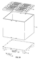
- a sleeve pack assembly 10 includes a pallet 12, a foldable/collapsible sleeve 14 and a top cap 16.
- the sleeve pack assembly 10 also includes a latching mechanism 18 located in a center foot 20 of the pallet 12. The latching mechanism 18 is for securing the sleeve 14 to the pallet 12.
- the sleeve 12 includes four sides and an open top and open bottom.
- the sleeve 12 can be a single piece, or can be formed from two or more pieces, such as one commonly referred to as a C-sleeve. As illustrated in Figures 2A and 2B , the sleeve opens to form the side walls of the pack, and folds for more compact shipment when empty.
- the sleeve is provided with two apertures 22 located proximate a bottom portion of at least one side wall (all of the side walls could include the apertures so that no special alignment of the sleeve to the pallet is necessary, or if additional latching mechanisms are provided on other sides of the pallet).
- the apertures 22 are spaced to align with components of the latching mechanism 18 which extend through the apertures 22 when the sleeve pack assembly 10 is set up as illustrated in Figure 4 .
- the sleeve 12 is designed to fold or collapse when not set-up as part of the assembly 10.
- the latching mechanism 18 includes an engagement panel or kick panel 24 (i.e., "kick,” because it can be operated by a user's foot) that is flush with an opening in a forward facing side of a foot 20 of the pallet 12.
- the kick panel 24 is connected to molded-in spring elements 26 (here, flexible bent pieces of plastic) as well as engagement members in the form of a first prong 28 and a second prong 29 (more fully shown in Figure 9 ).
- the engagement members cooperate with the apertures to secure the sleeve in place.
- the pallet 12 includes a trough or channel 30 proximate the side edges of the pallet for receiving a bottom portion of each side of the sleeve 14.
- the prongs 28, 29 are provided with inclined upper surfaces 32. As the bottom edge of the sleeve 14 is lowered into the channel 30, it contacts the upper surface of the prongs 32 and forces the prongs 28, 29 to slide backwards into the pallet 12.
- the prongs 28 are aligned with the apertures 22 of the sleeve and will spring back through the apertures 22 when the sleeve is lowered sufficiently into the channel 30, thus securing the sleeve 14 to the pallet 12. Accordingly, the latching mechanism is activated automatically during the set-up.
- the latching mechanism 18 is shown by itself in Figure 9 .
- the kick-panel 24 is connected directly to the spring elements 26 - one extending from each side of the kick-panel 24. While molded-in spring elements 26 are shown, other types of springs (whether molded-in or as separate components) or mechanisms (e.g., a hydraulic system) can be used.
- the center foot 20 is provided with a first aperture or window 34 aligned with the first prong 28 and a second aperture or window 35 aligned with the second prong 29.
- the windows 34, 35 allow a user to visually inspect the latch mechanism and ensure the prongs have captured and secured the sleeve 14 to the pallet 12.
- the kick-panel 24 is connected to a central shaft 36 which, in turn, is connected to a first arm 38 and a second arm 40.
- the first and second arms 38, 40 are connected to the first and second prongs 28, 29, respectively.
- the latching mechanism 18 fits into a holder 42 (shown without the latching mechanism 18 in Figure 10 ) formed on the lower side of the pallet 12 (preferably in one of the feet 42, such as a central foot).
- the holder 44 includes a first rectangular spring portion 44 which contains the kick-panel 24 and the spring elements 26.
- the spring portion 46 includes an opening 48 in the front for access to the kick-panel 24 and a smaller opening 50 in the back for the central shaft 36.
- the spring portion 46 includes a first back wall portion 52 and a second back wall portion 54.
- the sleeve 14 can be removed by pushing or pressing in the kick panel 24 (this can be done with the user's foot). When the kick-panel 24 is pressed inward the spring elements 26 compress against the back wall portions 52, 54 (this also occurs when the sleeve 14 contacts the inclined surfaces of the prongs 28, 29 and forces the prongs backward). Additionally, the central shaft 36 moves the first and second arms 38, 40 backward which in turn, moves the first and second prongs 28, 29 back out of the apertures in the sleeve 14. The sleeve 14 can then be lifted out of the channel 30.
- the spring elements 26 push the kick-panel 24 back in position flush with the outer wall of the foot 42.
- the latching mechanism 18 is biased in a closed position (the open position is when the prongs 28, 29 are pushed back to allow for removal of the sleeve 14).
- the first prong 28 is connected to the first arm 38 by a first positioning segment 58 having a central opening or slot 60.
- the second prong 29 is connected to the second arm 40 by a second positioning segment 62 having a central opening or slot 64.
- the central openings or slots 60, 64 have a generally oval shape. As noted below, the openings or slots 60, 64 cooperate with structure in the pallet 12 to act as a guide for the latching mechanism 18.
- the latching mechanism 18 also includes a first stop flap 66 connected by a living hinge 68 to the first positioning segment 58 proximate the first prong 28, and a second stop flap 70 connected by a living hinge 72 to the second positioning segment 62 proximate the second prong 29. As illustrated in Figures 11 and 12A and B , the stop flaps 66, 70 are folded over and snapped into place (when the latching mechanism 18 is inserted into the holder 42).
- the latching mechanism 18 is placed in the holder 44 so that a first boss 74 is positioned in the central opening 60 of the first positioning segment 58, and a second boss 76 is positioned in the central opening 64 of the second positioning segment 62.
- the bosses 74, 76 and openings 60, 64 function as guides during movement of the latching mechanism.
- Figure 11 also shows the stop flaps 66, 70 partially folded over into place.
- Figures 12A and 12B show the latching mechanism 18 in a closed position (with the kick-panel 24 flush with the outer surface of the foot) and a depressed (i.e., pushed-in) position, respectively.
- the flaps 66, 70 and bosses 74, 76 stop movement of the latching mechanism 18 inward and prevent it from moving too far.
- a latching mechanism as shown in the pallet 12 could be incorporated into a top cap or other similar structure applied to the top of a sleeve pack.
- the latch mechanism can be located in a corner foot of the pallet 12 or another portion of the pallet (e.g., between feet, or a side portion if the pallet does not include feet).
- the assembly could be formed with only one aperture and one prong, one long aperture or slot for two or more prongs, or two or more apertures and two or more prongs. Additionally, the assembly can include more than one latching mechanism (e.g., mechanisms on opposing sides of the pallet).
Landscapes
- Engineering & Computer Science (AREA)
- Mechanical Engineering (AREA)
- Pallets (AREA)
- Supplying Of Containers To The Packaging Station (AREA)
Abstract

Description
- The present invention claims the benefit of
U.S. Provisional Patent Application No. 61/804,882, filed March 25, 2013 U.S. Patent Application No. 14/039,040, filed September 27, 2013 , the contents of which are incorporated herein by reference. - The present invention generally relates to a latching mechanism having a forward facing engagement panel for use with a sleeve pack assembly, and more particularly to a latching mechanism for a sleeve pack assembly having an engagement panel that can be operated by a user's foot.
- Returnable bulk containers come in two general classifications, sleeve packs and knock downs. A sleeve pack includes a pallet, a sleeve and a top cap. To assemble and disassemble a sleeve pack today there are two options to retain (i.e., lock) the bottom portion of the sleeve to the pallet and the top portion of the sleeve to the top cap. These include (1) a passive interference fit, and (2) an active latching mechanism.
- The passive interference fit lock generally creates a weak engagement and/or is difficult to assemble, and can damage the sleeve. The active latching mechanisms available today require the operator to bend over or kneel and reach under the pallet to engage the lock.
- The present invention provides the desirable aspects of both designs, allowing for an easy passive latch assembly without the need to bend and reach, while providing a strong "lock" between the components. It also provides for active disengaging without the need to bend and reach.
- Additional aspects of the present invention are set forth herein.
- The present invention provides a spring loaded latching mechanism incorporated into a sleeve pack assembly. The latching mechanism is automatically engaged during set-up of the assembly (without requiring additional steps from the operator). The latching mechanism can be easily disengaged with a push or kick of the foot of the operator and does not require the operator to bend, kneel or reach for the mechanism.
- In accordance with one embodiment, the latching mechanism can be formed as a one piece, plastic spring which is particularly useful for instances requiring food safety. Other embodiments can be formed of multiple components and can include other materials, such as a steel spring.
- The latching mechanism can be implemented on any type of sleeve pack regardless of the number of sides in the sleeve. For example, the latching mechanism can be used for a sleeve pack with a sleeve having three sides, or for one having four or more sides such as an octagon shaped sleeve with eight sides. Moreover the latching mechanism could be implemented with a sleeve sidewall having curvature, such as a cylindrical shaped sleeve with a circular cross-section.
- In accordance with another embodiment, a sleeve pack assembly is provided with a latching mechanism that can be operated by a user in an upright position. The sleeve pack assembly comprises a sleeve having a first side, a second side, and a third side. Additionally, the sleeve can include a fourth side for a rectangular shape, or have more than four sides (such as an octagon shaped sleeve with eight sides). The sleeve is configured to have a first bottom opening and a second top opening when opened. When not in use, the sleeve can be folded and/or collapsed to provide for more efficient transport. At least one of the sides has a first aperture proximate a bottom portion of the at least one side.
- The assembly also includes a pallet having a plurality of feet forming a base of the assembly. The pallet includes a channel proximate a periphery for receiving a bottom edge portion of each side of the sleeve.
- The assembly also includes a latch mechanism having a spring element and a first prong coupled to the first spring element. The first prong is aligned with the first aperture of the sleeve such that the first prong extends through the first aperture when the sleeve is positioned in the channel. The latch mechanism also includes an engagement panel positioned on an outer surface of one of the plurality of feet, such as a center foot. Activation of the engagement panel (e.g., by an operator's foot) pushes back the spring element and the first prong, and disengages the first prong from the first aperture.
- The assembly can be configured so that the sleeve includes a second aperture proximate the bottom portion of the at least one side spaced from the first aperture, and the latch mechanism includes a second prong aligned with the second aperture of the sleeve. The second prong is positioned to extend through the second aperture when the sleeve is positioned in the channel.
- The first prong can include an inclined upper surface. This acts as a camming surface and moves the prong out of the way when installing the sleeve into the channel. Likewise, the second prong (and any additional prongs) can have an inclined upper surface.
- The foot housing the latch mechanism can include a first window aligned with the first prong (and a second window aligned with the second prong) to allow for visual inspection of the mechanism. This enables an operator to determine that the sleeve is secured to the pallet.
- The latch mechanism can be formed as a single plastic piece. Alternatively, the latch mechanism can include a plurality of components. In this alternative embodiment, the latch mechanism can include a steel spring element.
- The assembly can also include a top cap. The top cap can be configured to include a latch mechanism.
- The assembly can also include a first stop for preventing inward movement of the engagement panel past a set point. Similarly, the assembly can also include a second stop. The stops can include a flap that interacts with a boss in the pallet. The assembly can also include an opening or slot aligned with the boss to act as a guide for the latching mechanism.
- In accordance with another embodiment of the invention, a sleeve pack assembly is provided comprising a collapsible sleeve having a first side, a second side, and a third side. Again, the sleeve can have a fourth side or more than four sides. The sleeve has a bottom opening and a top opening, a bottom portion of at least one of the sides has a first aperture. The assembly includes a pallet having a latching mechanism for securing the sleeve to the pallet. The latching mechanism includes a forward facing engagement panel in a side of the pallet, and an engagement member aligned to engage the aperture of the sleeve. The pallet can include a plurality of feet wherein the latching mechanism is positioned in one of the feet.
- The latching mechanism further includes a spring element. The spring element can be a molded-in part integral with the engagement panel and engagement member. Alternatively, the spring element can be a separate component.
- The sleeve pack assembly can include a second aperture in the sleeve spaced from the first aperture. The engagement member can then include a first prong aligned with the first aperture and a second prong aligned with the second aperture.
- The latching mechanism can include a stop to prevent the engagement panel from being depressed beyond a set distance. The stop can be a flap that cooperates with structure in the pallet, such as a boss.
- Additionally, the latching mechanism can include a guide slot that cooperates with structure in the pallet. The structure can be the boss.
- Further aspects of the invention are disclosed in the Figures, and are described herein.
- To understand the present invention, it will now be described by way of example, with reference to the accompanying figures in which:
-
FIGURE 1 is a perspective view of a set-up sleeve pack assembly incorporating a latching mechanism in accordance with the present invention; -
FIGURES 2A and2B are exploded perspective views of the sleeve pack assembly ofFIGURE 1 in a set up and collapsed position, respectively; -
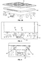
FIGURE 3 is a partially exploded perspective view of a bottom portion of a sleeve pack assembly; -
FIGURE 4 is a perspective view of a latch mechanism of an assembled sleeve pack assembly; -
FIGURE 5 is a bottom view of a latching mechanism of an assembled sleeve pack assembly; -
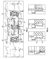
FIGURE 6 is a progressive series of cross-sectional views of a sleeve engaging a latching mechanism; -
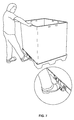
FIGURE 7 is a perspective of a user operating a latching mechanism of the present invention; -
FIGURE 8 is a perspective view of a user operating prior latching mechanisms. -
FIGURE 9 is a perspective view of a latching mechanism of the present invention prior to placement in a pallet; -
FIGURE 10 is a partial bottom perspective view of the portion of the pallet designed to hold the latching mechanism shown inFigure 9 ; -
FIGURE 11 is a partial bottom perspective view of the latching mechanism in a pallet with stop flaps partially folded; and, -
Figures 12A and 12B are partial bottom perspective views of the latching mechanism in a closed position and a depressed position, respectively. - While this invention is susceptible of embodiments in many different forms, there is shown in the Figures, and will herein be described in detail preferred embodiments of the invention with the understanding that the present disclosure is to be considered as an exemplification of the principles of the invention and is not intended to limit the broad aspect of the invention to the embodiments illustrated.
- As illustrated in
Figures 1 and2A and2B , asleeve pack assembly 10 includes apallet 12, a foldable/collapsible sleeve 14 and atop cap 16. Thesleeve pack assembly 10 also includes alatching mechanism 18 located in acenter foot 20 of thepallet 12. Thelatching mechanism 18 is for securing thesleeve 14 to thepallet 12. - The
sleeve 12 includes four sides and an open top and open bottom. Thesleeve 12 can be a single piece, or can be formed from two or more pieces, such as one commonly referred to as a C-sleeve. As illustrated inFigures 2A and2B , the sleeve opens to form the side walls of the pack, and folds for more compact shipment when empty. - As shown in
Figure 3 , the sleeve is provided with twoapertures 22 located proximate a bottom portion of at least one side wall (all of the side walls could include the apertures so that no special alignment of the sleeve to the pallet is necessary, or if additional latching mechanisms are provided on other sides of the pallet). Theapertures 22 are spaced to align with components of thelatching mechanism 18 which extend through theapertures 22 when thesleeve pack assembly 10 is set up as illustrated inFigure 4 . Thesleeve 12 is designed to fold or collapse when not set-up as part of theassembly 10. - As illustrated in the bottom view of
Figure 5 , thelatching mechanism 18 includes an engagement panel or kick panel 24 (i.e., "kick," because it can be operated by a user's foot) that is flush with an opening in a forward facing side of afoot 20 of thepallet 12. Thekick panel 24 is connected to molded-in spring elements 26 (here, flexible bent pieces of plastic) as well as engagement members in the form of afirst prong 28 and a second prong 29 (more fully shown inFigure 9 ). As discussed below, the engagement members cooperate with the apertures to secure the sleeve in place. - As shown in cross-section in
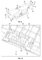
Figure 6 , thepallet 12 includes a trough orchannel 30 proximate the side edges of the pallet for receiving a bottom portion of each side of thesleeve 14. Referring toFigure 6 , theprongs sleeve 14 is lowered into thechannel 30, it contacts the upper surface of theprongs 32 and forces theprongs pallet 12. Theprongs 28 are aligned with theapertures 22 of the sleeve and will spring back through theapertures 22 when the sleeve is lowered sufficiently into thechannel 30, thus securing thesleeve 14 to thepallet 12. Accordingly, the latching mechanism is activated automatically during the set-up. - As illustrated in
Figure 7 , to remove the sleeve, pressure is applied to the kick-panel 24, pushing back thespring elements 26 and the attachedprongs 28 until the prongs disengage theapertures 22 in thesleeve 14. Thesleeve 14 can then be lifted out of thetrough 30 in thepallet 12 by the operator. In the past, the operator would have to kneel and reach under the pallet to disengage the latch as shown inFigure 8 . - The
latching mechanism 18 is shown by itself inFigure 9 . In this embodiment, the kick-panel 24 is connected directly to the spring elements 26 - one extending from each side of the kick-panel 24. While molded-inspring elements 26 are shown, other types of springs (whether molded-in or as separate components) or mechanisms (e.g., a hydraulic system) can be used. - As shown in
Figure 4 , thecenter foot 20 is provided with a first aperture orwindow 34 aligned with thefirst prong 28 and a second aperture orwindow 35 aligned with thesecond prong 29. Thewindows sleeve 14 to thepallet 12. - The kick-
panel 24 is connected to acentral shaft 36 which, in turn, is connected to afirst arm 38 and asecond arm 40. The first andsecond arms second prongs - The
latching mechanism 18 fits into a holder 42 (shown without thelatching mechanism 18 inFigure 10 ) formed on the lower side of the pallet 12 (preferably in one of the feet 42, such as a central foot). Theholder 44 includes a firstrectangular spring portion 44 which contains the kick-panel 24 and thespring elements 26. Thespring portion 46 includes anopening 48 in the front for access to the kick-panel 24 and asmaller opening 50 in the back for thecentral shaft 36. Thespring portion 46 includes a firstback wall portion 52 and a secondback wall portion 54. - The
sleeve 14 can be removed by pushing or pressing in the kick panel 24 (this can be done with the user's foot). When the kick-panel 24 is pressed inward thespring elements 26 compress against theback wall portions 52, 54 (this also occurs when thesleeve 14 contacts the inclined surfaces of theprongs central shaft 36 moves the first andsecond arms second prongs sleeve 14. Thesleeve 14 can then be lifted out of thechannel 30. - When pressure is released from the kick-
panel 24, thespring elements 26 push the kick-panel 24 back in position flush with the outer wall of the foot 42. In this manner, thelatching mechanism 18 is biased in a closed position (the open position is when theprongs - As shown in
Figure 9 , thefirst prong 28 is connected to thefirst arm 38 by afirst positioning segment 58 having a central opening or slot 60. Similarly, thesecond prong 29 is connected to thesecond arm 40 by asecond positioning segment 62 having a central opening orslot 64. The central openings orslots 60, 64 have a generally oval shape. As noted below, the openings orslots 60, 64 cooperate with structure in thepallet 12 to act as a guide for thelatching mechanism 18. - As also shown in
Figure 9 , thelatching mechanism 18 also includes afirst stop flap 66 connected by a living hinge 68 to thefirst positioning segment 58 proximate thefirst prong 28, and asecond stop flap 70 connected by a livinghinge 72 to thesecond positioning segment 62 proximate thesecond prong 29. As illustrated inFigures 11 and12A and B , the stop flaps 66, 70 are folded over and snapped into place (when thelatching mechanism 18 is inserted into the holder 42). - As illustrated in
Figure 11 , thelatching mechanism 18 is placed in theholder 44 so that afirst boss 74 is positioned in the central opening 60 of thefirst positioning segment 58, and asecond boss 76 is positioned in thecentral opening 64 of thesecond positioning segment 62. Thebosses openings 60, 64 function as guides during movement of the latching mechanism. -
Figure 11 also shows the stop flaps 66, 70 partially folded over into place.Figures 12A and 12B show thelatching mechanism 18 in a closed position (with the kick-panel 24 flush with the outer surface of the foot) and a depressed (i.e., pushed-in) position, respectively. As noted inFigure 12B , theflaps bosses latching mechanism 18 inward and prevent it from moving too far. - In one alternative embodiment, a latching mechanism as shown in the
pallet 12, could be incorporated into a top cap or other similar structure applied to the top of a sleeve pack. In another alternative embodiment, the latch mechanism can be located in a corner foot of thepallet 12 or another portion of the pallet (e.g., between feet, or a side portion if the pallet does not include feet). - While two apertures and two prongs are shown in the Figures, the assembly could be formed with only one aperture and one prong, one long aperture or slot for two or more prongs, or two or more apertures and two or more prongs. Additionally, the assembly can include more than one latching mechanism (e.g., mechanisms on opposing sides of the pallet).
- Many modifications and variations of the present invention are possible in light of the above teachings. It is, therefore, to be understood within the scope of the appended claims the invention may be protected otherwise than as specifically described.
- Further aspects of the invention are as follows:
- 1. A sleeve pack assembly comprising:
- a collapsible sleeve having a first side, a second side, and a third side, the sleeve having a bottom opening and a top opening, a bottom portion of at least one of the sides having a first aperture; and,
- a pallet having a latching mechanism for securing the sleeve to the pallet, the latching mechanism including a forward facing engagement panel in a side of the pallet, and an engagement member aligned to engage the aperture of the sleeve.
- 2. The sleeve pack assembly of 1 wherein the latching mechanism further includes a spring element.
- 3. The sleeve pack assembly of 2 wherein the spring element is a molded-in part integral with the engagement panel and engagement member.
- 4. The sleeve pack assembly of 1 wherein the sleeve includes a second aperture spaced from the first aperture and the engagement member includes a first prong aligned with the first aperture and a second prong aligned with the second aperture.
- 5. The sleeve pack assembly of 1 wherein the latching mechanism includes a stop to prevent the engagement panel from being depressed beyond a set distance.
- 6. The sleeve pack assembly of 1 wherein the latching mechanism includes a guide slot that cooperates with structure in the pallet.
- 7. The sleeve pack assembly of 1 wherein the pallet includes a plurality of legs.
Claims (13)
- A sleeve pack assembly comprising:a sleeve having a first side, a second side, and a third side, the sleeve having a first bottom opening and a second top opening, at least one of the sides having a first aperture proximate a bottom portion of the at least one side;a pallet having a plurality of feet forming a base of the assembly, the pallet including a channel for receiving a bottom edge portion of each side of the sleeve; and,a latch mechanism having a first spring element, a first prong coupled to the first spring element, the first prong being aligned with the first aperture of the sleeve wherein the first prong extends through the first aperture when the sleeve is positioned in the channel, and an engagement panel positioned on an outer surface of one of the plurality of feet wherein activation of the engagement panel disengages the first prong from the first aperture for release of the sleeve.
- The assembly of claim 1 wherein the sleeve includes a second aperture proximate the bottom portion of the at least one side spaced from the first aperture, and the latch mechanism includes a second prong aligned with the second aperture of the sleeve wherein the second prong extends through the second aperture when the sleeve is positioned in the channel.
- The assembly of claim 1 wherein the first prong includes an inclined upper surface.
- The assembly of claim 2 wherein the latch mechanism is positioned in a center foot of the pallet.
- The assembly of claim 4 wherein the center foot includes a first window aligned with the first prong and a second window aligned with the second prong to enable an operator to visually determine that the sleeve is secured to the pallet.
- The assembly of claim 1 wherein the latch mechanism is a single plastic piece.
- The assembly of claim 1 wherein the latch mechanism includes a steel spring element.
- The assembly of claim 1 wherein the latch mechanism includes a plurality of components.
- The assembly of claim 1 further comprising a top cap.
- The assembly of claim 1 wherein the spring element is biased toward a closed position and activation of the engagement panel compresses the spring element to move the first prong.
- The assembly of claim 1 further comprising a first stop for preventing inward movement of the engagement panel past a set point.
- The assembly of claim 11 wherein the first stop includes a flap that interacts with a boss in the pallet.
- The assembly of claim 1 wherein the latching mechanism includes an opening aligned with a boss in the pallet, the opening and boss acting as a guide for the latching mechanism.
Applications Claiming Priority (2)
| Application Number | Priority Date | Filing Date | Title |
|---|---|---|---|
| US201361804882P | 2013-03-25 | 2013-03-25 | |
| US14/039,040 US9487329B2 (en) | 2013-03-25 | 2013-09-27 | Sleeve pack assembly with latching mechanism |
Publications (2)
| Publication Number | Publication Date |
|---|---|
| EP2783996A1 true EP2783996A1 (en) | 2014-10-01 |
| EP2783996B1 EP2783996B1 (en) | 2017-04-19 |
Family
ID=49958259
Family Applications (1)
| Application Number | Title | Priority Date | Filing Date |
|---|---|---|---|
| EP14150885.3A Active EP2783996B1 (en) | 2013-03-25 | 2014-01-13 | Sleeve pack assembly with latching mechanism |
Country Status (3)
| Country | Link |
|---|---|
| US (2) | US9487329B2 (en) |
| EP (1) | EP2783996B1 (en) |
| ES (1) | ES2632785T3 (en) |
Cited By (6)
| Publication number | Priority date | Publication date | Assignee | Title |
|---|---|---|---|---|
| US9764876B2 (en) | 2015-01-02 | 2017-09-19 | Orbis Corporation | Sleeve pack assembly |
| US11577883B2 (en) | 2019-04-05 | 2023-02-14 | Orbis Corporation | Latch for a sleeve pack assembly |
| WO2023016942A3 (en) * | 2021-08-09 | 2023-04-13 | Atlas Elektronik Gmbh | Device for safely recovering and transporting weapons, in particular weapons found underwater |
| DE102023100600A1 (en) * | 2023-01-12 | 2024-07-18 | Mondi Ag | Packaging containers |
| EP4527755A1 (en) | 2023-09-21 | 2025-03-26 | Corplex France Wormhout | Pallet latch, latch mounting kit, latch installation method and associated pallet |
| US12344434B2 (en) | 2020-11-11 | 2025-07-01 | Cabka Group Gmbh | Collapsible container and method of operating a collapsible container |
Families Citing this family (9)
| Publication number | Priority date | Publication date | Assignee | Title |
|---|---|---|---|---|
| USD733426S1 (en) * | 2012-11-13 | 2015-07-07 | Daimler Ag | Transportation and storage container |
| US9487329B2 (en) * | 2013-03-25 | 2016-11-08 | Orbis Corporation | Sleeve pack assembly with latching mechanism |
| DE202016100228U1 (en) | 2016-01-19 | 2016-02-12 | Montara Verpacken Mit System Gmbh | Lid for a stackable transport pallet |
| CN107499648B (en) * | 2017-09-26 | 2023-02-03 | 宁波喜悦智行科技股份有限公司 | Plastic protection box composed of top cover, coaming and tray |
| US10532853B2 (en) * | 2018-01-05 | 2020-01-14 | Easy Gardener Products, Inc. | Product display container |
| CN109606921B (en) * | 2018-11-19 | 2020-06-05 | 佛山高威彩印包装有限公司 | Novel packaging box |
| GB2591078B (en) * | 2019-12-20 | 2024-05-15 | Chep Technology Pty Ltd | Pallet |
| USD895924S1 (en) | 2020-03-16 | 2020-09-08 | Big 3 Precision Products, Inc. | Pallet |
| USD1096056S1 (en) | 2023-07-11 | 2025-09-30 | Big 3 Precision Products, Inc. | Shipping base |
Citations (7)
| Publication number | Priority date | Publication date | Assignee | Title |
|---|---|---|---|---|
| FR2126521A5 (en) * | 1971-02-09 | 1972-10-06 | Peugeot Cycles | |
| WO2006132613A1 (en) * | 2005-06-03 | 2006-12-14 | Linpac Materials Handling | Container assembly and latch apparatus, and related methods |
| DE102005031526A1 (en) * | 2005-06-30 | 2007-04-12 | Söhner Kunststofftechnik GmbH Präzisionsthermoformen | Transport container and palette base has folded wall ring on a palette base with offset outer contour at junction between lower thin-walled and upper thick-walled wall regions |
| GB2440327A (en) * | 2006-07-27 | 2008-01-30 | Ds Smith Plastics Ltd | A packaging module compringing a sleeve coupled to a pallet |
| JP2008308194A (en) * | 2007-06-14 | 2008-12-25 | Kawakami Sangyo Co Ltd | Shipping container |
| JP2009107703A (en) * | 2007-10-31 | 2009-05-21 | Kawakami Sangyo Co Ltd | Shipping container |
| EP2256051A1 (en) * | 2009-05-29 | 2010-12-01 | KTP Kunstostoff Palettentechnik GmbH | Pallet container with side walls and cover |
Family Cites Families (69)
| Publication number | Priority date | Publication date | Assignee | Title |
|---|---|---|---|---|
| US3374915A (en) * | 1966-07-21 | 1968-03-26 | Verhein Donald | Collapsible and stackable container |
| US3797691A (en) * | 1972-05-10 | 1974-03-19 | Lockheed Aircraft Corp | Modular cargo container for transport vehicles |
| US3926412A (en) * | 1974-02-04 | 1975-12-16 | Technifil S A | Gravity catch for hinged guard fences |
| US3966072A (en) * | 1974-06-13 | 1976-06-29 | Fairchild Industries Inc. | Collapsible container |
| US4209183A (en) * | 1977-11-15 | 1980-06-24 | Twil Handling Systems Limited | Load carrying pallets |
| CA1098057A (en) * | 1979-03-20 | 1981-03-24 | Seiji Takeuchi | Shipping assembly |
| US4453471A (en) * | 1981-06-04 | 1984-06-12 | Hb Clip-Lok Industries Ltd. | Panel retaining clamp for collapsible pallet containers |
| US4936451A (en) * | 1986-04-23 | 1990-06-26 | Shuert Lyle H | Container with sleeve interlocking latch |
| US4626155A (en) * | 1986-01-13 | 1986-12-02 | Maclean-Fogg Company | Automatic container securement device with a spring biased, cam surfaced head |
| US4720013A (en) | 1986-08-28 | 1988-01-19 | Bradford Company | Nestable and stackable tray |
| US4746053A (en) | 1987-04-09 | 1988-05-24 | Bradford Company | Interiorly locked partition assembly |
| US4798290A (en) | 1987-12-10 | 1989-01-17 | Bradford Company | Electrostatic discharge carton |
| US4966280B1 (en) | 1988-05-04 | 1997-03-25 | Bradford Co | Multiple-ply anti-static paperboard |
| US5017260A (en) | 1989-04-12 | 1991-05-21 | Bradford Company | Anti-static coated paperboard or similar rigid material |
| US5161709A (en) * | 1989-01-30 | 1992-11-10 | World Container Corporation | Hinged collapsible container |
| US5037027A (en) | 1990-12-18 | 1991-08-06 | Bradford Company | Tote box construction |
| US5123541A (en) * | 1991-03-26 | 1992-06-23 | Penda Corporation | Modular shipping container and clip for assembling components thereof |
| US5109985A (en) * | 1991-06-07 | 1992-05-05 | Formall/Blackwood Corporation | End cap locking means for a palletized container |
| US5295632B1 (en) | 1992-12-18 | 1998-04-21 | Bradford Co | Tote box with self locking top rail |
| AU1873395A (en) * | 1994-02-14 | 1995-08-29 | Bradford Company | Collapsible pallet box |
| US5522539A (en) | 1994-12-16 | 1996-06-04 | Bradford Company | Tote box with block insert locking capability |
| US5462221A (en) | 1995-01-04 | 1995-10-31 | Bradford Company | Tote box handle |
| US5597084A (en) * | 1995-02-17 | 1997-01-28 | Canadian Plywood Association | Collapsible pallet bin |
| US5722328A (en) * | 1995-06-06 | 1998-03-03 | T.H.E.M. International, Inc. | Pallet system including side wall latch assembly |
| US5813566A (en) | 1995-07-12 | 1998-09-29 | Bradford Company | Damage resistant container and sleeve pack assembly |
| US5732876A (en) | 1995-11-20 | 1998-03-31 | Bradford Company | Welded partition assembly |
| US5597113A (en) | 1995-11-20 | 1997-01-28 | Bradford Company | Recyclable container partition |
| US5908135A (en) * | 1995-11-21 | 1999-06-01 | Bradford Company | Sleeve pack |
| US5788146A (en) | 1996-02-13 | 1998-08-04 | Bradford Company | Parent welding partition assembly |
| US6540096B1 (en) | 1996-02-28 | 2003-04-01 | Bradford Company | Collapsible container with integrally supported dunnage and side entry |
| US5725119A (en) | 1996-02-28 | 1998-03-10 | Bradford Company | Collapsible container with integrally supported |
| US5725118A (en) * | 1996-04-12 | 1998-03-10 | Bradford Company | Modular side-loading container system |
| US5862917A (en) * | 1997-09-30 | 1999-01-26 | Trienda Corporation | Pallet sleeve clip with visible positive open and closed positions |
| US6024223A (en) * | 1999-02-04 | 2000-02-15 | Technology Container Corporation | Storage container including a mounting clip an associated mounting clip, and an associated method |
| WO2000078617A1 (en) | 1999-06-18 | 2000-12-28 | Bradford Company | Tote box with corner enhancers and top rail |
| US6592025B2 (en) | 1999-06-18 | 2003-07-15 | Bradford Company | Tote box with corner enhancers, clips and top rail |
| USD455266S1 (en) | 2000-09-07 | 2002-04-09 | Bradford Company | Tote box top rail corner piece |
| US6349877B1 (en) | 2000-09-08 | 2002-02-26 | Bradford Company | Tote box with corner enhancers and multiple piece top rail |
| US6547127B2 (en) | 2000-09-08 | 2003-04-15 | Bradford Company | Tote box with multiple piece top rail including corner pieces with projections |
| US6902061B1 (en) * | 2000-09-29 | 2005-06-07 | Paul Elstone | Collapsible liquid box |
| USD454692S1 (en) | 2001-04-04 | 2002-03-26 | Bradford Company | Top rail corner piece |
| US6460724B1 (en) | 2001-04-11 | 2002-10-08 | Bradford Company | Tote box with interengaging top rail |
| US8109402B2 (en) * | 2001-10-04 | 2012-02-07 | Schoeller Arca Systems Ab | Collapsible container for transport and storage |
| US6564993B1 (en) | 2002-04-22 | 2003-05-20 | Bradford Company | Tote box with corner enhancers and strengthener clips |
| US6619540B1 (en) | 2002-04-22 | 2003-09-16 | Bradford Company | Snap lock tote box handle and tote box construction |
| DE20215597U1 (en) | 2002-10-10 | 2003-04-10 | Conteyor Multibag Systems N.V., Merelbeke | Collapsible frame |
| US7380358B2 (en) | 2002-10-10 | 2008-06-03 | Bradford Company | Injection molded, recessed insert for use in a container and method for using same |
| US7428975B2 (en) | 2003-07-29 | 2008-09-30 | Bradford Company | Combination of partition assembly and container and method of use |
| US7556170B2 (en) | 2004-01-20 | 2009-07-07 | Bradford Company | Lightweight stackable horizontal dispensing container |
| US7258232B2 (en) | 2004-10-14 | 2007-08-21 | Bradford Company | Partially collapsible and partially expandable dunnage system for use in a horizontal dispensing container |
| US7083369B2 (en) | 2004-12-08 | 2006-08-01 | Bradford Company | Collapsible container with dunnage erection biaser |
| US7410094B2 (en) | 2004-12-13 | 2008-08-12 | Bradford Company | Multi-level partition assembly |
| US7322485B2 (en) | 2004-12-21 | 2008-01-29 | Bradford Company | Pouch assembly for use in a container |
| US8100283B2 (en) | 2005-01-14 | 2012-01-24 | Bradford Company | Dunnage structure made with multiple ply partitions |
| US8079490B2 (en) | 2005-01-14 | 2011-12-20 | Bradford Company | Dunnage structure made with multiple ply partitions |
| US7344044B2 (en) | 2005-01-14 | 2008-03-18 | Bradford Company | Partition assembly having floor parent welded to partitions |
| US7344043B2 (en) | 2005-01-14 | 2008-03-18 | Bradford Company | Partition assembly made with multiple ply partitions |
| US7762422B2 (en) | 2005-05-05 | 2010-07-27 | Bradford Company | Container having non-linear support members for supporting dunnage |
| US7748559B2 (en) | 2005-05-05 | 2010-07-06 | Bradford Company | Container having sloped movable support member assemblies for supporting dunnage |
| US20060249415A1 (en) | 2005-05-05 | 2006-11-09 | Bradford Company | Container having sliding support members |
| US7654408B2 (en) | 2005-09-06 | 2010-02-02 | Bradford Company | Container with locking strips |
| US7540390B2 (en) | 2005-09-15 | 2009-06-02 | Bradford Company | Collapsible container for air shipment cargo |
| JP4912796B2 (en) * | 2006-08-30 | 2012-04-11 | キョーラク株式会社 | Assembled container |
| US7748803B2 (en) | 2006-10-02 | 2010-07-06 | Bradford Company | Horizontal dispensing container having multiple removable, sliding, hinged shelves |
| US8061549B2 (en) | 2008-09-23 | 2011-11-22 | Bradford Company | Dunnage structure made with multiple ply partitions |
| US7775419B2 (en) | 2009-01-13 | 2010-08-17 | Bradford Company | Non-diassembling intersecting partition matrix and method of manufacture |
| US8112859B2 (en) | 2009-03-24 | 2012-02-14 | Bradford Company | Method of manufacturing custom sized plastic tote having intermediate sleeve |
| DE102010014349A1 (en) * | 2010-04-09 | 2011-10-13 | Schoeller Arca Systems Gmbh | Bulk containers |
| US9487329B2 (en) * | 2013-03-25 | 2016-11-08 | Orbis Corporation | Sleeve pack assembly with latching mechanism |
-
2013
- 2013-09-27 US US14/039,040 patent/US9487329B2/en active Active
-
2014
- 2014-01-13 EP EP14150885.3A patent/EP2783996B1/en active Active
- 2014-01-13 ES ES14150885.3T patent/ES2632785T3/en active Active
-
2016
- 2016-10-17 US US15/295,412 patent/US20170029166A1/en not_active Abandoned
Patent Citations (7)
| Publication number | Priority date | Publication date | Assignee | Title |
|---|---|---|---|---|
| FR2126521A5 (en) * | 1971-02-09 | 1972-10-06 | Peugeot Cycles | |
| WO2006132613A1 (en) * | 2005-06-03 | 2006-12-14 | Linpac Materials Handling | Container assembly and latch apparatus, and related methods |
| DE102005031526A1 (en) * | 2005-06-30 | 2007-04-12 | Söhner Kunststofftechnik GmbH Präzisionsthermoformen | Transport container and palette base has folded wall ring on a palette base with offset outer contour at junction between lower thin-walled and upper thick-walled wall regions |
| GB2440327A (en) * | 2006-07-27 | 2008-01-30 | Ds Smith Plastics Ltd | A packaging module compringing a sleeve coupled to a pallet |
| JP2008308194A (en) * | 2007-06-14 | 2008-12-25 | Kawakami Sangyo Co Ltd | Shipping container |
| JP2009107703A (en) * | 2007-10-31 | 2009-05-21 | Kawakami Sangyo Co Ltd | Shipping container |
| EP2256051A1 (en) * | 2009-05-29 | 2010-12-01 | KTP Kunstostoff Palettentechnik GmbH | Pallet container with side walls and cover |
Cited By (7)
| Publication number | Priority date | Publication date | Assignee | Title |
|---|---|---|---|---|
| US9764876B2 (en) | 2015-01-02 | 2017-09-19 | Orbis Corporation | Sleeve pack assembly |
| US11577883B2 (en) | 2019-04-05 | 2023-02-14 | Orbis Corporation | Latch for a sleeve pack assembly |
| US12344434B2 (en) | 2020-11-11 | 2025-07-01 | Cabka Group Gmbh | Collapsible container and method of operating a collapsible container |
| WO2023016942A3 (en) * | 2021-08-09 | 2023-04-13 | Atlas Elektronik Gmbh | Device for safely recovering and transporting weapons, in particular weapons found underwater |
| DE102023100600A1 (en) * | 2023-01-12 | 2024-07-18 | Mondi Ag | Packaging containers |
| EP4527755A1 (en) | 2023-09-21 | 2025-03-26 | Corplex France Wormhout | Pallet latch, latch mounting kit, latch installation method and associated pallet |
| FR3153335A1 (en) | 2023-09-21 | 2025-03-28 | Corplex France Wormhout | Pallet latch |
Also Published As
| Publication number | Publication date |
|---|---|
| EP2783996B1 (en) | 2017-04-19 |
| US20140284247A1 (en) | 2014-09-25 |
| US9487329B2 (en) | 2016-11-08 |
| US20170029166A1 (en) | 2017-02-02 |
| ES2632785T3 (en) | 2017-09-15 |
Similar Documents
| Publication | Publication Date | Title |
|---|---|---|
| US9487329B2 (en) | Sleeve pack assembly with latching mechanism | |
| CN101528555B (en) | Modular container | |
| US10894631B2 (en) | Foldable crate | |
| US9474369B1 (en) | Shelving apparatus | |
| US9723925B1 (en) | Foldable post for shelving apparatus | |
| US8348076B2 (en) | Collapsible container with locking device | |
| EP3119253B1 (en) | Portable toilet device for a small child | |
| EP1655232B1 (en) | Folding container | |
| EP0552153A1 (en) | A container. | |
| EP2508443A1 (en) | Storage container | |
| KR101763588B1 (en) | Packaging paper box | |
| EP1160169A2 (en) | A plastic box with collapsible walls provided with folding support legs | |
| KR20190067744A (en) | Bottom structure of the packaging box and packaging box comprising the same | |
| KR102424744B1 (en) | Folding box | |
| JP3805462B2 (en) | Deployable assembly container and assembly container locking structure | |
| KR200395104Y1 (en) | Folding box | |
| US9938053B2 (en) | Container having a closable loading opening | |
| JP2002068187A (en) | Box pallet | |
| EP3456648B1 (en) | Stackable crate provided with slidingly extractable shelves | |
| JP4400813B2 (en) | Assembled plastic container | |
| KR102523660B1 (en) | assembly container one touch clip receive box | |
| JP2005313978A (en) | Joint device and assembly type container using it | |
| CN102602580B (en) | Connector and transfer container with same | |
| KR101977144B1 (en) | Packing box | |
| JP2011051628A (en) | Folding type container |
Legal Events
| Date | Code | Title | Description |
|---|---|---|---|
| 17P | Request for examination filed |
Effective date: 20140113 |
|
| AK | Designated contracting states |
Kind code of ref document: A1 Designated state(s): AL AT BE BG CH CY CZ DE DK EE ES FI FR GB GR HR HU IE IS IT LI LT LU LV MC MK MT NL NO PL PT RO RS SE SI SK SM TR |
|
| AX | Request for extension of the european patent |
Extension state: BA ME |
|
| PUAI | Public reference made under article 153(3) epc to a published international application that has entered the european phase |
Free format text: ORIGINAL CODE: 0009012 |
|
| R17P | Request for examination filed (corrected) |
Effective date: 20150310 |
|
| RBV | Designated contracting states (corrected) |
Designated state(s): AL AT BE BG CH CY CZ DE DK EE ES FI FR GB GR HR HU IE IS IT LI LT LU LV MC MK MT NL NO PL PT RO RS SE SI SK SM TR |
|
| 17Q | First examination report despatched |
Effective date: 20151109 |
|
| GRAP | Despatch of communication of intention to grant a patent |
Free format text: ORIGINAL CODE: EPIDOSNIGR1 |
|
| INTG | Intention to grant announced |
Effective date: 20160627 |
|
| GRAJ | Information related to disapproval of communication of intention to grant by the applicant or resumption of examination proceedings by the epo deleted |
Free format text: ORIGINAL CODE: EPIDOSDIGR1 |
|
| GRAP | Despatch of communication of intention to grant a patent |
Free format text: ORIGINAL CODE: EPIDOSNIGR1 |
|
| INTC | Intention to grant announced (deleted) | ||
| INTG | Intention to grant announced |
Effective date: 20161118 |
|
| GRAS | Grant fee paid |
Free format text: ORIGINAL CODE: EPIDOSNIGR3 |
|
| GRAA | (expected) grant |
Free format text: ORIGINAL CODE: 0009210 |
|
| AK | Designated contracting states |
Kind code of ref document: B1 Designated state(s): AL AT BE BG CH CY CZ DE DK EE ES FI FR GB GR HR HU IE IS IT LI LT LU LV MC MK MT NL NO PL PT RO RS SE SI SK SM TR |
|
| REG | Reference to a national code |
Ref country code: GB Ref legal event code: FG4D |
|
| REG | Reference to a national code |
Ref country code: CH Ref legal event code: EP |
|
| REG | Reference to a national code |
Ref country code: AT Ref legal event code: REF Ref document number: 885696 Country of ref document: AT Kind code of ref document: T Effective date: 20170515 |
|
| REG | Reference to a national code |
Ref country code: IE Ref legal event code: FG4D |
|
| REG | Reference to a national code |
Ref country code: DE Ref legal event code: R096 Ref document number: 602014008644 Country of ref document: DE |
|
| REG | Reference to a national code |
Ref country code: NL Ref legal event code: MP Effective date: 20170419 |
|
| REG | Reference to a national code |
Ref country code: LT Ref legal event code: MG4D |
|
| REG | Reference to a national code |
Ref country code: ES Ref legal event code: FG2A Ref document number: 2632785 Country of ref document: ES Kind code of ref document: T3 Effective date: 20170915 Ref country code: AT Ref legal event code: MK05 Ref document number: 885696 Country of ref document: AT Kind code of ref document: T Effective date: 20170419 |
|
| PG25 | Lapsed in a contracting state [announced via postgrant information from national office to epo] |
Ref country code: NL Free format text: LAPSE BECAUSE OF FAILURE TO SUBMIT A TRANSLATION OF THE DESCRIPTION OR TO PAY THE FEE WITHIN THE PRESCRIBED TIME-LIMIT Effective date: 20170419 |
|
| PG25 | Lapsed in a contracting state [announced via postgrant information from national office to epo] |
Ref country code: GR Free format text: LAPSE BECAUSE OF FAILURE TO SUBMIT A TRANSLATION OF THE DESCRIPTION OR TO PAY THE FEE WITHIN THE PRESCRIBED TIME-LIMIT Effective date: 20170720 Ref country code: HR Free format text: LAPSE BECAUSE OF FAILURE TO SUBMIT A TRANSLATION OF THE DESCRIPTION OR TO PAY THE FEE WITHIN THE PRESCRIBED TIME-LIMIT Effective date: 20170419 Ref country code: NO Free format text: LAPSE BECAUSE OF FAILURE TO SUBMIT A TRANSLATION OF THE DESCRIPTION OR TO PAY THE FEE WITHIN THE PRESCRIBED TIME-LIMIT Effective date: 20170719 Ref country code: AT Free format text: LAPSE BECAUSE OF FAILURE TO SUBMIT A TRANSLATION OF THE DESCRIPTION OR TO PAY THE FEE WITHIN THE PRESCRIBED TIME-LIMIT Effective date: 20170419 Ref country code: LT Free format text: LAPSE BECAUSE OF FAILURE TO SUBMIT A TRANSLATION OF THE DESCRIPTION OR TO PAY THE FEE WITHIN THE PRESCRIBED TIME-LIMIT Effective date: 20170419 Ref country code: FI Free format text: LAPSE BECAUSE OF FAILURE TO SUBMIT A TRANSLATION OF THE DESCRIPTION OR TO PAY THE FEE WITHIN THE PRESCRIBED TIME-LIMIT Effective date: 20170419 |
|
| PG25 | Lapsed in a contracting state [announced via postgrant information from national office to epo] |
Ref country code: LV Free format text: LAPSE BECAUSE OF FAILURE TO SUBMIT A TRANSLATION OF THE DESCRIPTION OR TO PAY THE FEE WITHIN THE PRESCRIBED TIME-LIMIT Effective date: 20170419 Ref country code: RS Free format text: LAPSE BECAUSE OF FAILURE TO SUBMIT A TRANSLATION OF THE DESCRIPTION OR TO PAY THE FEE WITHIN THE PRESCRIBED TIME-LIMIT Effective date: 20170419 Ref country code: IS Free format text: LAPSE BECAUSE OF FAILURE TO SUBMIT A TRANSLATION OF THE DESCRIPTION OR TO PAY THE FEE WITHIN THE PRESCRIBED TIME-LIMIT Effective date: 20170819 Ref country code: PL Free format text: LAPSE BECAUSE OF FAILURE TO SUBMIT A TRANSLATION OF THE DESCRIPTION OR TO PAY THE FEE WITHIN THE PRESCRIBED TIME-LIMIT Effective date: 20170419 Ref country code: BG Free format text: LAPSE BECAUSE OF FAILURE TO SUBMIT A TRANSLATION OF THE DESCRIPTION OR TO PAY THE FEE WITHIN THE PRESCRIBED TIME-LIMIT Effective date: 20170719 Ref country code: SE Free format text: LAPSE BECAUSE OF FAILURE TO SUBMIT A TRANSLATION OF THE DESCRIPTION OR TO PAY THE FEE WITHIN THE PRESCRIBED TIME-LIMIT Effective date: 20170419 |
|
| REG | Reference to a national code |
Ref country code: DE Ref legal event code: R097 Ref document number: 602014008644 Country of ref document: DE |
|
| REG | Reference to a national code |
Ref country code: FR Ref legal event code: PLFP Year of fee payment: 5 |
|
| PG25 | Lapsed in a contracting state [announced via postgrant information from national office to epo] |
Ref country code: RO Free format text: LAPSE BECAUSE OF FAILURE TO SUBMIT A TRANSLATION OF THE DESCRIPTION OR TO PAY THE FEE WITHIN THE PRESCRIBED TIME-LIMIT Effective date: 20170419 Ref country code: SK Free format text: LAPSE BECAUSE OF FAILURE TO SUBMIT A TRANSLATION OF THE DESCRIPTION OR TO PAY THE FEE WITHIN THE PRESCRIBED TIME-LIMIT Effective date: 20170419 Ref country code: DK Free format text: LAPSE BECAUSE OF FAILURE TO SUBMIT A TRANSLATION OF THE DESCRIPTION OR TO PAY THE FEE WITHIN THE PRESCRIBED TIME-LIMIT Effective date: 20170419 Ref country code: EE Free format text: LAPSE BECAUSE OF FAILURE TO SUBMIT A TRANSLATION OF THE DESCRIPTION OR TO PAY THE FEE WITHIN THE PRESCRIBED TIME-LIMIT Effective date: 20170419 Ref country code: CZ Free format text: LAPSE BECAUSE OF FAILURE TO SUBMIT A TRANSLATION OF THE DESCRIPTION OR TO PAY THE FEE WITHIN THE PRESCRIBED TIME-LIMIT Effective date: 20170419 |
|
| PLBE | No opposition filed within time limit |
Free format text: ORIGINAL CODE: 0009261 |
|
| STAA | Information on the status of an ep patent application or granted ep patent |
Free format text: STATUS: NO OPPOSITION FILED WITHIN TIME LIMIT |
|
| PG25 | Lapsed in a contracting state [announced via postgrant information from national office to epo] |
Ref country code: SM Free format text: LAPSE BECAUSE OF FAILURE TO SUBMIT A TRANSLATION OF THE DESCRIPTION OR TO PAY THE FEE WITHIN THE PRESCRIBED TIME-LIMIT Effective date: 20170419 |
|
| 26N | No opposition filed |
Effective date: 20180122 |
|
| PG25 | Lapsed in a contracting state [announced via postgrant information from national office to epo] |
Ref country code: SI Free format text: LAPSE BECAUSE OF FAILURE TO SUBMIT A TRANSLATION OF THE DESCRIPTION OR TO PAY THE FEE WITHIN THE PRESCRIBED TIME-LIMIT Effective date: 20170419 |
|
| REG | Reference to a national code |
Ref country code: CH Ref legal event code: PL |
|
| PG25 | Lapsed in a contracting state [announced via postgrant information from national office to epo] |
Ref country code: LU Free format text: LAPSE BECAUSE OF NON-PAYMENT OF DUE FEES Effective date: 20180113 |
|
| REG | Reference to a national code |
Ref country code: IE Ref legal event code: MM4A |
|
| PG25 | Lapsed in a contracting state [announced via postgrant information from national office to epo] |
Ref country code: LI Free format text: LAPSE BECAUSE OF NON-PAYMENT OF DUE FEES Effective date: 20180131 Ref country code: CH Free format text: LAPSE BECAUSE OF NON-PAYMENT OF DUE FEES Effective date: 20180131 |
|
| PG25 | Lapsed in a contracting state [announced via postgrant information from national office to epo] |
Ref country code: IE Free format text: LAPSE BECAUSE OF NON-PAYMENT OF DUE FEES Effective date: 20180113 |
|
| PG25 | Lapsed in a contracting state [announced via postgrant information from national office to epo] |
Ref country code: MC Free format text: LAPSE BECAUSE OF FAILURE TO SUBMIT A TRANSLATION OF THE DESCRIPTION OR TO PAY THE FEE WITHIN THE PRESCRIBED TIME-LIMIT Effective date: 20170419 |
|
| PG25 | Lapsed in a contracting state [announced via postgrant information from national office to epo] |
Ref country code: MT Free format text: LAPSE BECAUSE OF NON-PAYMENT OF DUE FEES Effective date: 20180113 |
|
| PG25 | Lapsed in a contracting state [announced via postgrant information from national office to epo] |
Ref country code: TR Free format text: LAPSE BECAUSE OF FAILURE TO SUBMIT A TRANSLATION OF THE DESCRIPTION OR TO PAY THE FEE WITHIN THE PRESCRIBED TIME-LIMIT Effective date: 20170419 |
|
| PG25 | Lapsed in a contracting state [announced via postgrant information from national office to epo] |
Ref country code: HU Free format text: LAPSE BECAUSE OF FAILURE TO SUBMIT A TRANSLATION OF THE DESCRIPTION OR TO PAY THE FEE WITHIN THE PRESCRIBED TIME-LIMIT; INVALID AB INITIO Effective date: 20140113 Ref country code: PT Free format text: LAPSE BECAUSE OF FAILURE TO SUBMIT A TRANSLATION OF THE DESCRIPTION OR TO PAY THE FEE WITHIN THE PRESCRIBED TIME-LIMIT Effective date: 20170419 |
|
| PG25 | Lapsed in a contracting state [announced via postgrant information from national office to epo] |
Ref country code: CY Free format text: LAPSE BECAUSE OF FAILURE TO SUBMIT A TRANSLATION OF THE DESCRIPTION OR TO PAY THE FEE WITHIN THE PRESCRIBED TIME-LIMIT Effective date: 20170419 Ref country code: MK Free format text: LAPSE BECAUSE OF NON-PAYMENT OF DUE FEES Effective date: 20170419 |
|
| PG25 | Lapsed in a contracting state [announced via postgrant information from national office to epo] |
Ref country code: AL Free format text: LAPSE BECAUSE OF FAILURE TO SUBMIT A TRANSLATION OF THE DESCRIPTION OR TO PAY THE FEE WITHIN THE PRESCRIBED TIME-LIMIT Effective date: 20170419 |
|
| PGFP | Annual fee paid to national office [announced via postgrant information from national office to epo] |
Ref country code: GB Payment date: 20251224 Year of fee payment: 13 |
|
| PGFP | Annual fee paid to national office [announced via postgrant information from national office to epo] |
Ref country code: FR Payment date: 20251226 Year of fee payment: 13 |
|
| PGFP | Annual fee paid to national office [announced via postgrant information from national office to epo] |
Ref country code: BE Payment date: 20251231 Year of fee payment: 13 |
|
| PGFP | Annual fee paid to national office [announced via postgrant information from national office to epo] |
Ref country code: ES Payment date: 20260203 Year of fee payment: 13 |
|
| PGFP | Annual fee paid to national office [announced via postgrant information from national office to epo] |
Ref country code: DE Payment date: 20251226 Year of fee payment: 13 |
|
| PGFP | Annual fee paid to national office [announced via postgrant information from national office to epo] |
Ref country code: IT Payment date: 20260107 Year of fee payment: 13 |