EP2783979A1 - Method and apparatus for providing a current return network in an aircraft structure - Google Patents
Method and apparatus for providing a current return network in an aircraft structure Download PDFInfo
- Publication number
- EP2783979A1 EP2783979A1 EP14162814.9A EP14162814A EP2783979A1 EP 2783979 A1 EP2783979 A1 EP 2783979A1 EP 14162814 A EP14162814 A EP 14162814A EP 2783979 A1 EP2783979 A1 EP 2783979A1
- Authority
- EP
- European Patent Office
- Prior art keywords
- zone
- return network
- current return
- assembly
- aircraft
- Prior art date
- Legal status (The legal status is an assumption and is not a legal conclusion. Google has not performed a legal analysis and makes no representation as to the accuracy of the status listed.)
- Granted
Links
Images


Classifications
-
- H—ELECTRICITY
- H05—ELECTRIC TECHNIQUES NOT OTHERWISE PROVIDED FOR
- H05F—STATIC ELECTRICITY; NATURALLY-OCCURRING ELECTRICITY
- H05F3/00—Carrying-off electrostatic charges
-
- B—PERFORMING OPERATIONS; TRANSPORTING
- B64—AIRCRAFT; AVIATION; COSMONAUTICS
- B64C—AEROPLANES; HELICOPTERS
- B64C1/00—Fuselages; Constructional features common to fuselages, wings, stabilising surfaces or the like
- B64C1/06—Frames; Stringers; Longerons ; Fuselage sections
- B64C1/12—Construction or attachment of skin panels
-
- B—PERFORMING OPERATIONS; TRANSPORTING
- B64—AIRCRAFT; AVIATION; COSMONAUTICS
- B64D—EQUIPMENT FOR FITTING IN OR TO AIRCRAFT; FLIGHT SUITS; PARACHUTES; ARRANGEMENT OR MOUNTING OF POWER PLANTS OR PROPULSION TRANSMISSIONS IN AIRCRAFT
- B64D45/00—Aircraft indicators or protectors not otherwise provided for
- B64D45/02—Lightning protectors; Static dischargers
-
- H—ELECTRICITY
- H05—ELECTRIC TECHNIQUES NOT OTHERWISE PROVIDED FOR
- H05K—PRINTED CIRCUITS; CASINGS OR CONSTRUCTIONAL DETAILS OF ELECTRIC APPARATUS; MANUFACTURE OF ASSEMBLAGES OF ELECTRICAL COMPONENTS
- H05K13/00—Apparatus or processes specially adapted for manufacturing or adjusting assemblages of electric components
-
- Y—GENERAL TAGGING OF NEW TECHNOLOGICAL DEVELOPMENTS; GENERAL TAGGING OF CROSS-SECTIONAL TECHNOLOGIES SPANNING OVER SEVERAL SECTIONS OF THE IPC; TECHNICAL SUBJECTS COVERED BY FORMER USPC CROSS-REFERENCE ART COLLECTIONS [XRACs] AND DIGESTS
- Y10—TECHNICAL SUBJECTS COVERED BY FORMER USPC
- Y10T—TECHNICAL SUBJECTS COVERED BY FORMER US CLASSIFICATION
- Y10T29/00—Metal working
- Y10T29/49—Method of mechanical manufacture
- Y10T29/49002—Electrical device making
- Y10T29/49117—Conductor or circuit manufacturing
Definitions
- Certain aspects of the disclosure relate generally to a current return network in an aircraft. More specifically, certain embodiments of the disclosure relate to a method and assembly wherein the current return network functions as both a current return network (CRN) and also as a load-bearing support for at least a portion of the aircraft.
- CRN current return network
- Weather conditions may have many elements, including winds, temperatures, lightning, thunder, icing conditions, rain, snow, turbulence caused by weather fronts, fog, smog, tornadoes, and hurricanes. Weather conditions are important, not only to the passengers but also to airlines, air traffic control personnel, weathermen, pilots and crew.
- Lightning is one specific weather element that may occur during air travel. It has been reported that, on average, an aircraft is struck by lightning only about once in a given year. Historically, commercial aircraft have generally included aluminum skin which is electrically conductive. In the event that there is a lightning strike on an aluminum skinned aircraft, the strike commonly enters at an extremity of the aircraft, such as at the nose or other zone. The electrical energy or current carried by the strike typically passes through the aluminum electrically conductive skin of the aircraft and then exits the aircraft at another extremity, such as at the tail. No harm typically occurs to the passengers or to any of the equipment on board.
- the current return network assembly provided on aircraft is not usually a great concern, particularly in aluminum aircraft, which itself may comprise a large portion of such a current return network.
- a current return network assembly for an aircraft having a predetermined potential lightning strike zone, is mounted within the predetermined potential lightning strike zone.
- the current return network assembly includes an electrically conductive honeycomb central core that conducts electrical current both through the assembly and through the predetermined potential lightning strike zone. The electrical current is caused by a lightning strike on the aircraft at the predetermined potential lightning strike zone.
- an aircraft having a predetermined potential lightning strike zone has an inner portion.
- a current return network assembly is mounted at the zone and within the inner portion of the predetermined potential lightning strike zone.
- An electrically conductive honeycomb central core portion is provided as a component of the current return network assembly. The central core portion conducts electrical current through the honeycomb core and also through the zone. The electrical current that is conducted is caused by a lightning strike on the aircraft at the zone.
- a method for constructing a current return network assembly used in aircraft.
- the method includes the steps of initially identifying a potential lightning strike zone on the aircraft wherein the zone is made of a material that it is at least partially of low electrical conductivity.
- the method includes the step of identifying a replaceable member in the zone that is capable of being usefully replaced by the current return network assembly.
- the next step involves determining at least one physical requirement of the replaceable member in the zone.
- the next step is providing the current return network assembly with an electrically conductive honeycomb central core that is capable of conducting electrical current through the core and through the zone when electrical current is caused by a lightning strike at the zone.
- the final step is constructing the assembly having the physical requirements of the replaceable member of the aircraft.
- the honeycomb central core is constructed of aluminum.
- the current return network assembly is constructed to provide load-bearing support for the predetermined potential lightning strike zone.
- the honeycomb central core has spaced ends and spaced sides interconnected by the ends, the sides; the ends and the core cooperating to at least partially provide the load-bearing support.
- the current return network assembly includes electrically conductive end cap members mounted on the ends of the core to cooperate with the core in conducting the electrical current through the assembly, the end cap members at least partially providing additional of the load-bearing support.
- the current return network includes side sheets which are partially electrically conductive and are bonded to the sides of the core, the side sheets, the end caps, and the core cooperating to provide the load-bearing support and to cooperate in conducting the electrical current through the assembly and the zone.
- the aircraft is at least partially constructed of a composite material in the zone.
- the zone comprises a vertical stabilizer of the aircraft.
- an aircraft comprising:
- the zone is at least partially constructed of a composite material in the zone.
- the zone comprises a vertical stabilizer of the aircraft.
- the honeycomb central core includes spaced ends, spaced sides interconnected by the ends, the sides, and the core cooperating for at least partially providing the load-bearing support for the vertical stabilizer.
- the current return network includes a plurality of electrically conductive end caps mounted on the ends of the core to cooperate with the core in conducting the electrical current through the assembly and the current return network further including side members which are partially electrically conductive and are bonded to the side of the core, the side members, the end caps, and the core cooperating in conducting the electrical current through the assembly.
- the assembly is constructed to provide structural load-bearing support for the potential lightning strike zone of the aircraft.
- a method for constructing a current return network assembly for use in an aircraft comprising the steps of:
- the step of determining the at least one design parameter includes determining a plurality of dimensions of the replaceable member and the constructing step includes constructing the current network assembly with the dimensions.
- the determining step includes determining multiple design parameters of the replaceable member and the method includes the step of installing the current return network assembly in the aircraft zone in a location originally designed for the replaceable member, the current return network assembly having the replaceable member design parameters in the zone and having the current return network capability in the event there is a future lightning strike at the zone, and the core conducting electrical current from the lightning strike zone through both the zone and through the honeycomb core in the event there is a future lightning strike at the zone.
- the potential lightning strike zone of the aircraft is a vertical stabilizer.
- the replaceable member in the zone is a load-bearing member.
- the step of determining the at least one design parameter includes determining load-bearing requirements of the replaceable member and the constructing step includes constructing the current return network assembly to include the load-bearing requirements of the replaceable member.
- the step of determining the at least one design parameter includes the further step of determining a plurality of dimensions of the replaceable member, and the constructing step includes constructing the current return network assembly with the dimensions of the replaceable member.
- an aircraft comprising the current return network assembly of any preceding embodiment.
- the description of the current return network assembly is primarily directed to use with commercial aircraft of the type that uses significant amounts of composite material including use on the fuselage, wings and tail section. However, it is to be understood that the current return network may also be used with aircraft primarily constructed of aluminum components as opposed to composite components.
- CFRP carbon fiber reinforced plastic
- CFRP may refer equally to Carbon fiber reinforced polymer, carbon fiber reinforced plastic, carbon fiber reinforced thermoplastic, or carbon filled plastic to describe a strong and light weight fiber-reinforced polymer which contains or may be filled with carbon fibers.
- the aircraft 50 includes a central fuselage, generally 52, having a nose section 54 having a pair of laterally projecting wings 56 fixedly secured to opposite sides of the fuselage 52. Jet engines 58 are fixedly mounted on each of the wings 56.
- the aircraft 50 further includes a tail section, generally 60, which includes a pair of laterally projecting horizontal stabilizers 62 and a vertical stabilizer (sometimes referred to as a fin), generally 64, projecting upwardly from the central rear portion of the fuselage 52 of the aircraft 50 and is part of the tail section 60, that includes a leading edge portion 66.
- a tail section generally 60, which includes a pair of laterally projecting horizontal stabilizers 62 and a vertical stabilizer (sometimes referred to as a fin), generally 64, projecting upwardly from the central rear portion of the fuselage 52 of the aircraft 50 and is part of the tail section 60, that includes a leading edge portion 66.
- FIG. 3 there is shown an enlarged cross-sectional view of the leading edge portion 66 of the vertical stabilizer 64.
- Fig. 3 is a prior art section along the line 3-3 of Fig. 2 illustrating the leading edge portion 66 of the vertical stabilizer 64 that is partially broken.
- an auxiliary aluminum spar, generally 68 Positioned rearward of the leading edge portion 66 of the vertical stabilizer 64, there is provided an auxiliary aluminum spar, generally 68, of conventional design.
- the spar 68 has a solid unitary central web section 70 having laterally spaced unitary flanges 72.
- the spar 68 provides structural support generally for the leading edge portion 66 of the vertical stabilizer 64, as illustrated in Figs. 1-3 .
- Certain zones of the aircraft 50 may have a higher incidence of a potential rare lightning strike on the aircraft 50 in a location that may have significant amounts of composite material used thereon, including on the fuselage 52, wings 56, and tail section 60.
- the following description relates to the use of the current return network assembly 100 used on the aircraft 50.
- the current return network assembly 100 has a dual function in that the current return network assembly 100 provides a structural substitute or replacement for the aluminum spar 68 shown in Fig. 3 and further provides a current return network for any rare lightning strike that may occur at the vertical stabilizer 64.
- lightning strike zones on the aircraft 50 may include the outer tips of the wings 56, the horizontal stabilizers 64, the vertical stabilizer 62, and the nose 56. These are the zones of the aircraft 50 where a current return network assembly 100 of the present description may beneficially be installed. It is to be understood that there may be additional locations that may be selected other than identified above. Further, it is to be understood that the current return network assembly 100 is primarily expected to be used on aircraft containing composite materials such as on the skin of the aircraft, but use of the current return network assembly 100 is not intended to be limited to such uses.
- the current return network assembly 100 is illustrated and is used in one or more of the potential lightning strike zones.
- the current return network assembly 100 will be described in connection with installation within the vertical stabilizer 64 schematically shown in Fig. 4 . Further. It is to be understood that the particular size and shape of the current return network assembly 100 may vary from the description herein depending on the specific zone where the current return network assembly is used on the aircraft 50.
- the current return network assembly includes a central core section, generally 102, a left side support flange assembly, generally 104, and a right side support flange, generally 106.
- the flange 104 is angled inwardly from right to left, while the flange 106 is angled inwardly from right to left.
- the reason for the angling of the flange 104 and flange 106 is that the flanges 104 and 106 are be used as support members to replace the aluminum spar 68 which has inwardly angled flanges 72 as illustrated in the prior art Fig. 3 . This aspect will be described herein in greater detail.
- the central core 102 as shown in Figs. 5-8 and in particular in Fig. 7 , comprises a central honeycomb core section 108 which is comprised of hollow hexagonal interconnected structural unitary tubes illustrated best in Fig. 7 and Fig. 9 .
- the honeycomb core section 108 is transversely positioned relative to the laterally opposed sides 110 that perform a load-bearing structure for the central core assembly 102.
- the sides 110 of the honeycomb section 108 are enclosed by a pair of outer supporting sheets 114 which cover the sides 110 and provide added structural support for the honeycomb core 108.
- the ends 116 of the honeycomb core 108 are also covered by end caps 118 as seen best in Fig. 8 .
- the end caps 118 are removed for illustration purposes in Fig. 7.
- honeycomb core section 108 does, however, show the supporting side sheets 114 enclosing the ends 116 of the honeycomb structure 108.
- the honeycomb core section 108, the side sheets 114, and the end caps 118 cooperate to provide a structurally sound central core section that is sized and shaped to be used not only as a current return network (CRN) but also as a load-bearing support that replaces the aluminum spar 68 illustrated in Fig.3 .
- CRM current return network
- the upper flange 104 and the lower flange 106 are constructed in substantially the same manner.
- the lower flange 106 is schematically shown and includes a pi-joint member 120 and a composite plank member 122.
- the plank member 122 is securely mounted below and against the pi-joint member 120 and is bonded thereto.
- the upper flange 104 has a similar pi-joint member 120 and plank member 122 bonded to the pi-joint member120.
- Each pi-joint member 120 comprises a plate portion 124 and a pair of upright laterally spaced portions 126 which define a central space there between for securely receiving and supporting the upper and lower ends of the central core section 102 by the upper flange assembly 104 and by the lower flange assembly 106, respectively.
- the upright portions 126 are unitarily formed with the plate portion 124.
- the central core section 102 is constructed of an electrically conducting material.
- the central honeycomb core 108 is constructed of aluminum. Titanium may also be used although it does not have as high an electrical conductivity.
- the side sheets 114 of the current return network assembly are preferably made of titanium or made of a carbon fiber reinforced plastic (CFRP) material both of which have a relatively low electrical conductivity.
- the pi-joint members 120 used at the upper flange 104 and lower flange 106 are constructed of a carbon fiber reinforced plastic material or of titanium.
- the plank members 122 that are bonded to the pi-joints 120 at both the upper flange 104 and lower flange 106 are preferably constructed of a carbon fiber reinforced plastic material.
- the plank members 122 are designed to bear against the opposed inner sides of the vertical stabilizer 64 as illustrated in Fig. 3A .
- the end caps 118 are preferably made of aluminum although copper may also be used. Both metals are electrically conductive but aluminum is preferred since aluminum is lighter in weight than copper.
- the current return network assembly 100 will cause the electric current from the lightning strike to pass from the exterior of one side of the vertical stabilizer 64 through the honeycomb core and outwardly, such as through the opposite side of the current return network assembly 100 and through the wall of the vertical stabilizer 64.
- the method for constructing the load-bearing current return network assembly 100 first requires the step of identifying a potential lightning strike zone on the aircraft 50. Once such a zone is identified, the next step is to identify an existing component of the aircraft 50 that may be replaced by the current return network assembly 100. As discussed above, a potential lightning strike zone includes the vertical stabilizer 64 of the aircraft 50, and the auxiliary spar 68 is identified as being an aircraft component capable of being usefully replaced by appropriately designing the current return network assembly 100.
- the design parameters for the current return network assembly 100 are based upon the previously established design parameters of the auxiliary spar 68.
- the design parameters for the current network assembly 100 extend over a wide range and include, but are not limited to, (1) the overall dimensions of the current return network assembly 100 required for properly fitting into the available space within the vertical stabilizer 64 and adjacent other structure within the vertical stabilizer, (2) the load-bearing requirements for supporting the vertical stabilizer 64, (3) the coefficient of thermal expansion required for the current return network 100 to become a replacement for the auxiliary spar 64, (4) corrosion resistance requirements for the current return network assembly 100, (5) damage tolerance during manufacture, installation and service of the current return network assembly 100, and possibly other design parameters.
- the current return network assembly 100 is designed and constructed with the identified design parameters so the current return network assembly 100 is acceptable for use as a replacement for the auxiliary spar 68. It is to be understood that the auxiliary spar 68 is only one replaceable member of the aircraft 50 that can be replaced by a properly designed current return network assembly 100 depending on the particular location on the aircraft 50 that is selected to have the current return network assembly 100 installed.
- the current return network assembly 100 is constructed with the central core section 102 and honeycomb core 108 with the supporting side sheets 114 and end caps 118. Finally, the top and bottom of the central core section 102 are installed on the previously joined pi-joints 120 and plank members 122 that define the upper and lower flanges 104 and 106. The current return network assembly 100 is then ready for installation and is installed in a location of the aircraft 50 as a replacement for the auxiliary spar 68 for which the current return network assembly 100 has been designed and constructed, that is, within the vertical stabilizer 64 as a replacement for the aluminum spar 68 as shown in Fig.3 .
Landscapes
- Engineering & Computer Science (AREA)
- Aviation & Aerospace Engineering (AREA)
- Mechanical Engineering (AREA)
- Manufacturing & Machinery (AREA)
- Microelectronics & Electronic Packaging (AREA)
- Elimination Of Static Electricity (AREA)
- Wind Motors (AREA)
Abstract
Description
- Certain aspects of the disclosure relate generally to a current return network in an aircraft. More specifically, certain embodiments of the disclosure relate to a method and assembly wherein the current return network functions as both a current return network (CRN) and also as a load-bearing support for at least a portion of the aircraft.
- Possibly, the greatest variable in air travel is weather. Weather conditions may have many elements, including winds, temperatures, lightning, thunder, icing conditions, rain, snow, turbulence caused by weather fronts, fog, smog, tornadoes, and hurricanes. Weather conditions are important, not only to the passengers but also to airlines, air traffic control personnel, weathermen, pilots and crew.
- Lightning is one specific weather element that may occur during air travel. It has been reported that, on average, an aircraft is struck by lightning only about once in a given year. Historically, commercial aircraft have generally included aluminum skin which is electrically conductive. In the event that there is a lightning strike on an aluminum skinned aircraft, the strike commonly enters at an extremity of the aircraft, such as at the nose or other zone. The electrical energy or current carried by the strike typically passes through the aluminum electrically conductive skin of the aircraft and then exits the aircraft at another extremity, such as at the tail. No harm typically occurs to the passengers or to any of the equipment on board.
- In the case of modem aircraft using at least some composite materials such as on the outer skin, additional measures are usually taken because such composite materials are not as electrically conductive when compared with an aluminum skin aircraft. One such measure includes a current return network assembly which may be provided at various locations on the partially composite aircraft. It is to be understood that the composite aircraft is not entirely composite and that there are areas of conductive material, such as aluminum, used on certain portions of the aircraft.
- In the design of aircraft, the weight of various components is typically very important. The current return network assembly provided on aircraft is not usually a great concern, particularly in aluminum aircraft, which itself may comprise a large portion of such a current return network. However, with composite aircraft, it would be highly desirable to provide a current return network assembly that does not add weight to the aircraft because a reduction in the weight of an aircraft typically increases fuel efficiency.
- Further limitations and disadvantages of conventional and traditional approaches will become apparent to one of skill in the art, through comparison of such approaches with the present disclosure as set forth in the remainder of the present application including the drawings.
- According to an embodiment a current return network assembly, for an aircraft having a predetermined potential lightning strike zone, is mounted within the predetermined potential lightning strike zone. The current return network assembly includes an electrically conductive honeycomb central core that conducts electrical current both through the assembly and through the predetermined potential lightning strike zone. The electrical current is caused by a lightning strike on the aircraft at the predetermined potential lightning strike zone.
- According to a further embodiment, an aircraft having a predetermined potential lightning strike zone has an inner portion. A current return network assembly is mounted at the zone and within the inner portion of the predetermined potential lightning strike zone. An electrically conductive honeycomb central core portion is provided as a component of the current return network assembly. The central core portion conducts electrical current through the honeycomb core and also through the zone. The electrical current that is conducted is caused by a lightning strike on the aircraft at the zone.
- According to yet a further embodiment, a method is provided for constructing a current return network assembly used in aircraft. The method includes the steps of initially identifying a potential lightning strike zone on the aircraft wherein the zone is made of a material that it is at least partially of low electrical conductivity. The method includes the step of identifying a replaceable member in the zone that is capable of being usefully replaced by the current return network assembly. The next step involves determining at least one physical requirement of the replaceable member in the zone. The next step is providing the current return network assembly with an electrically conductive honeycomb central core that is capable of conducting electrical current through the core and through the zone when electrical current is caused by a lightning strike at the zone. The final step is constructing the assembly having the physical requirements of the replaceable member of the aircraft.
- Further, the disclosure comprises embodiments according to the following clauses:
- In another embodiment, there is provided an aircraft having a predetermined potential lightning strike zone and having a current return network assembly for mounting within the zone, the assembly comprising:
- an electrically conductive honeycomb central core for conducting electrical current through the assembly, and the zone, the electrical current having been caused by a lightning strike on the aircraft at the zone.
- Optionally, the honeycomb central core is constructed of aluminum.
- Optionally, the current return network assembly is constructed to provide load-bearing support for the predetermined potential lightning strike zone.
- Optionally, the honeycomb central core has spaced ends and spaced sides interconnected by the ends, the sides; the ends and the core cooperating to at least partially provide the load-bearing support.
- Optionally, the current return network assembly, includes electrically conductive end cap members mounted on the ends of the core to cooperate with the core in conducting the electrical current through the assembly, the end cap members at least partially providing additional of the load-bearing support.
- Optionally, the current return network, includes side sheets which are partially electrically conductive and are bonded to the sides of the core, the side sheets, the end caps, and the core cooperating to provide the load-bearing support and to cooperate in conducting the electrical current through the assembly and the zone.
- Optionally, the aircraft is at least partially constructed of a composite material in the zone.
- Optionally, the zone comprises a vertical stabilizer of the aircraft.
- In another embodiment, there is provided in an aircraft, the aircraft comprising:
- a pre-determined potential lightning strike zone having an inner portion;
- a current return network assembly mounted at the zone within the inner portion; and
- an electrically conductive honeycomb central core portion as a component of the current return network assembly for conducting electrical current through the core and through the zone, the electrical current being caused by a lightning strike on the aircraft at the zone.
- Optionally, the zone is at least partially constructed of a composite material in the zone.
- Optionally, the zone comprises a vertical stabilizer of the aircraft.
- Optionally, the honeycomb central core includes spaced ends, spaced sides interconnected by the ends, the sides, and the core cooperating for at least partially providing the load-bearing support for the vertical stabilizer.
- Optionally, the current return network includes a plurality of electrically conductive end caps mounted on the ends of the core to cooperate with the core in conducting the electrical current through the assembly and the current return network further including side members which are partially electrically conductive and are bonded to the side of the core, the side members, the end caps, and the core cooperating in conducting the electrical current through the assembly.
- Optionally, the assembly is constructed to provide structural load-bearing support for the potential lightning strike zone of the aircraft.
- In another embodiment, there is provided a method for constructing a current return network assembly for use in an aircraft, the method comprising the steps of:
- identifying a potential lightning strike zone on the aircraft, the zone being made of a material at least partially of low electrical conductivity;
- identifying a replaceable member in the zone capable of being usefully replaced by the current return network assembly;
- determining at least one design parameter of the replaceable member in the zone;
- providing the current return network assembly with an electrically conductive honeycomb central core capable of conducting electrical current through the core and through the zone wherein the electrical current is caused by the lightning strike; and
- constructing the assembly having the at least one design parameter of the replaceable member.
- Optionally, the step of determining the at least one design parameter includes determining a plurality of dimensions of the replaceable member and the constructing step includes constructing the current network assembly with the dimensions.
- Optionally, the determining step includes determining multiple design parameters of the replaceable member and the method includes the step of installing the current return network assembly in the aircraft zone in a location originally designed for the replaceable member, the current return network assembly having the replaceable member design parameters in the zone and having the current return network capability in the event there is a future lightning strike at the zone, and the core conducting electrical current from the lightning strike zone through both the zone and through the honeycomb core in the event there is a future lightning strike at the zone.
- Optionally, the potential lightning strike zone of the aircraft is a vertical stabilizer.
- Optionally, the replaceable member in the zone is a load-bearing member.
- Optionally, the step of determining the at least one design parameter includes determining load-bearing requirements of the replaceable member and the constructing step includes constructing the current return network assembly to include the load-bearing requirements of the replaceable member.
- Optionally, the step of determining the at least one design parameter includes the further step of determining a plurality of dimensions of the replaceable member, and the constructing step includes constructing the current return network assembly with the dimensions of the replaceable member.
- In another embodiment, there is provided an aircraft comprising the current return network assembly of any preceding embodiment.
- The features, functions, and advantages that have been discussed above can be achieved independently in various embodiments or may be combined in yet other embodiments, further details of which can be seen with reference to the following description and drawings.
-
-
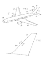
Fig. 1 is an illustration of an aircraft having one or more zones within which the current return network assembly can be installed; -
Fig. 2 is an illustration of a vertical stabilizer of the aircraft shown inFig. 1 wherein the current return network assembly may be installed; -
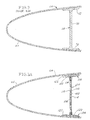
Fig. 3 is an enlarged cross sectional view taken along the lines 3-3 ofFig. 2 showing the leading edge of the prior art vertical stabilizer ofFig. 2 and wherein an auxiliary support spar is provided; -
Fig. 3A is a view similar toFig. 3 showing the use of the current return network assembly that replaces the spar illustrated in the prior artFig. 3 ; -
Fig. 4 is a perspective view of the return network assembly shown inFig. 3A . -
Fig. 5 is an enlarged view illustrating a portion of the current return network ofFig. 4 ; -
Fig. 6 is further enlarged view of an upper end portion of the current return network assembly shown inFig. 5 ; -
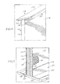
Fig. 7 is an illustration showing a lower end portion of the current return network assembly ofFigs. 3A and4-6 and specifically illustrates a partial cross sectional view of the honeycomb core thereof; -
Fig. 8 is an illustration showing a pi-joint and an end cap at one end of the assembly ofFigs. 3A and4-7 ; and -
Fig 9 is detailed view of a portion of the honeycomb core of the assembly ofFigs. 3A and4-8 . - The following description and the accompanying drawings set out below provide details of the current return network assembly and method for making such an assembly. The description, as follows, is not to be considered in a limiting sense but it is provided for the purpose of illustrating the general principles of the claims relating to the described current network assembly and method for manufacture. The scope of the disclosure will be defined by the claims that follow the detailed description.
- The description of the current return network assembly is primarily directed to use with commercial aircraft of the type that uses significant amounts of composite material including use on the fuselage, wings and tail section. However, it is to be understood that the current return network may also be used with aircraft primarily constructed of aluminum components as opposed to composite components.
- Referring to
Fig. 1 , there is provided an illustration of an aircraft, generally 50. Theaircraft 50, as discussed above, is primarily directed to an aircraft of modem design using significant amounts of composite materials such as carbon fiber reinforced plastic (CFRP) materials. As used herein, CFRP may refer equally to Carbon fiber reinforced polymer, carbon fiber reinforced plastic, carbon fiber reinforced thermoplastic, or carbon filled plastic to describe a strong and light weight fiber-reinforced polymer which contains or may be filled with carbon fibers. Theaircraft 50 includes a central fuselage, generally 52, having anose section 54 having a pair of laterally projectingwings 56 fixedly secured to opposite sides of thefuselage 52.Jet engines 58 are fixedly mounted on each of thewings 56. Theaircraft 50 further includes a tail section, generally 60, which includes a pair of laterally projectinghorizontal stabilizers 62 and a vertical stabilizer (sometimes referred to as a fin), generally 64, projecting upwardly from the central rear portion of thefuselage 52 of theaircraft 50 and is part of thetail section 60, that includes aleading edge portion 66. - Referring to
Fig.3 , there is shown an enlarged cross-sectional view of theleading edge portion 66 of thevertical stabilizer 64. Specifically,Fig. 3 is a prior art section along the line 3-3 ofFig. 2 illustrating theleading edge portion 66 of thevertical stabilizer 64 that is partially broken. Positioned rearward of theleading edge portion 66 of thevertical stabilizer 64, there is provided an auxiliary aluminum spar, generally 68, of conventional design. Thespar 68 has a solid unitarycentral web section 70 having laterally spacedunitary flanges 72. Thespar 68 provides structural support generally for theleading edge portion 66 of thevertical stabilizer 64, as illustrated inFigs. 1-3 . - Certain zones of the
aircraft 50 may have a higher incidence of a potential rare lightning strike on theaircraft 50 in a location that may have significant amounts of composite material used thereon, including on thefuselage 52,wings 56, andtail section 60. The following description relates to the use of the currentreturn network assembly 100 used on theaircraft 50. As will be described in more detail, the currentreturn network assembly 100 has a dual function in that the currentreturn network assembly 100 provides a structural substitute or replacement for thealuminum spar 68 shown inFig. 3 and further provides a current return network for any rare lightning strike that may occur at thevertical stabilizer 64. - As described above, lightning strike zones on the
aircraft 50 may include the outer tips of thewings 56, thehorizontal stabilizers 64, thevertical stabilizer 62, and thenose 56. These are the zones of theaircraft 50 where a currentreturn network assembly 100 of the present description may beneficially be installed. It is to be understood that there may be additional locations that may be selected other than identified above. Further, it is to be understood that the currentreturn network assembly 100 is primarily expected to be used on aircraft containing composite materials such as on the skin of the aircraft, but use of the currentreturn network assembly 100 is not intended to be limited to such uses. - Referring to
Fig. 4 , the currentreturn network assembly 100 is illustrated and is used in one or more of the potential lightning strike zones. For purposes of illustration herein, the currentreturn network assembly 100 will be described in connection with installation within thevertical stabilizer 64 schematically shown inFig. 4 . Further. It is to be understood that the particular size and shape of the currentreturn network assembly 100 may vary from the description herein depending on the specific zone where the current return network assembly is used on theaircraft 50. - Referring to
Fig. 3A andFig. 4 , the current return network assembly includes a central core section, generally 102, a left side support flange assembly, generally 104, and a right side support flange, generally 106. Referring toFig. 3A , as illustrated, theflange 104 is angled inwardly from right to left, while theflange 106 is angled inwardly from right to left. The reason for the angling of theflange 104 andflange 106 is that theflanges aluminum spar 68 which has inwardly angledflanges 72 as illustrated in the prior artFig. 3 . This aspect will be described herein in greater detail. - The
central core 102, as shown inFigs. 5-8 and in particular inFig. 7 , comprises a centralhoneycomb core section 108 which is comprised of hollow hexagonal interconnected structural unitary tubes illustrated best inFig. 7 andFig. 9 . Thehoneycomb core section 108 is transversely positioned relative to the laterally opposedsides 110 that perform a load-bearing structure for thecentral core assembly 102. Thesides 110 of thehoneycomb section 108 are enclosed by a pair of outer supportingsheets 114 which cover thesides 110 and provide added structural support for thehoneycomb core 108. The ends 116 of thehoneycomb core 108 are also covered byend caps 118 as seen best inFig. 8 . The end caps 118 are removed for illustration purposes inFig. 7. Fig. 7 does, however, show the supportingside sheets 114 enclosing theends 116 of thehoneycomb structure 108. Thehoneycomb core section 108, theside sheets 114, and the end caps 118 cooperate to provide a structurally sound central core section that is sized and shaped to be used not only as a current return network (CRN) but also as a load-bearing support that replaces thealuminum spar 68 illustrated inFig.3 . - Referring to
Figs. 4, 5 and8 , theupper flange 104 and thelower flange 106 are constructed in substantially the same manner. Referring toFig. 8 , thelower flange 106 is schematically shown and includes a pi-joint member 120 and acomposite plank member 122. Theplank member 122 is securely mounted below and against the pi-joint member 120 and is bonded thereto. It is to be understood that theupper flange 104 has a similar pi-joint member 120 andplank member 122 bonded to the pi-joint member120. - Each pi-
joint member 120 comprises aplate portion 124 and a pair of upright laterally spacedportions 126 which define a central space there between for securely receiving and supporting the upper and lower ends of thecentral core section 102 by theupper flange assembly 104 and by thelower flange assembly 106, respectively. Theupright portions 126 are unitarily formed with theplate portion 124. - Since the current
return network assembly 100 provides for the passage of electrical current generated by a lightning strike in the area of thevertical stabilizer 64, thecentral core section 102 is constructed of an electrically conducting material. Preferably, thecentral honeycomb core 108 is constructed of aluminum. Titanium may also be used although it does not have as high an electrical conductivity. Theside sheets 114 of the current return network assembly are preferably made of titanium or made of a carbon fiber reinforced plastic (CFRP) material both of which have a relatively low electrical conductivity. Preferably, the pi-joint members 120 used at theupper flange 104 andlower flange 106 are constructed of a carbon fiber reinforced plastic material or of titanium. Theplank members 122 that are bonded to the pi-joints 120 at both theupper flange 104 andlower flange 106 are preferably constructed of a carbon fiber reinforced plastic material. Theplank members 122 are designed to bear against the opposed inner sides of thevertical stabilizer 64 as illustrated inFig. 3A . The end caps 118 are preferably made of aluminum although copper may also be used. Both metals are electrically conductive but aluminum is preferred since aluminum is lighter in weight than copper. - In the case of a lightning strike in the area of the
vertical stabilizer 64, the currentreturn network assembly 100 will cause the electric current from the lightning strike to pass from the exterior of one side of thevertical stabilizer 64 through the honeycomb core and outwardly, such as through the opposite side of the currentreturn network assembly 100 and through the wall of thevertical stabilizer 64. - As has been described above, the current
return network assembly 100 is preferably designed, constructed, and installed at a potential lightning strike zone on theaircraft 50. In the case of installing the currentreturn network assembly 100 in thevertical stabilizer 64, the currentreturn network assembly 100 is designed to replace the use of thealuminum spar 68 as shown in prior artFig. 3 . By replacing the aluminum auxiliary spar 68 with the currentreturn network assembly 100, there is a saving in weight and a saving in expense since the currentreturn network assembly 100 functions as a load-bearing support in replacing thealuminum spar 68 in thevertical stabilizer zone 64 and also functions as a current return network (CRN) for theaircraft 50. - The method for constructing the load-bearing current
return network assembly 100 first requires the step of identifying a potential lightning strike zone on theaircraft 50. Once such a zone is identified, the next step is to identify an existing component of theaircraft 50 that may be replaced by the currentreturn network assembly 100. As discussed above, a potential lightning strike zone includes thevertical stabilizer 64 of theaircraft 50, and theauxiliary spar 68 is identified as being an aircraft component capable of being usefully replaced by appropriately designing the currentreturn network assembly 100. - Once the
auxiliary spar 68 has been identified as being usefully replaced by a suitably designed currentreturn network assembly 100, the design parameters for the currentreturn network assembly 100 are based upon the previously established design parameters of theauxiliary spar 68. The design parameters for thecurrent network assembly 100 extend over a wide range and include, but are not limited to, (1) the overall dimensions of the currentreturn network assembly 100 required for properly fitting into the available space within thevertical stabilizer 64 and adjacent other structure within the vertical stabilizer, (2) the load-bearing requirements for supporting thevertical stabilizer 64, (3) the coefficient of thermal expansion required for thecurrent return network 100 to become a replacement for theauxiliary spar 64, (4) corrosion resistance requirements for the currentreturn network assembly 100, (5) damage tolerance during manufacture, installation and service of the currentreturn network assembly 100, and possibly other design parameters. Once the design parameters have been determined, the currentreturn network assembly 100 is designed and constructed with the identified design parameters so the currentreturn network assembly 100 is acceptable for use as a replacement for theauxiliary spar 68. It is to be understood that theauxiliary spar 68 is only one replaceable member of theaircraft 50 that can be replaced by a properly designed currentreturn network assembly 100 depending on the particular location on theaircraft 50 that is selected to have the currentreturn network assembly 100 installed. - The current
return network assembly 100 is constructed with thecentral core section 102 andhoneycomb core 108 with the supportingside sheets 114 andend caps 118. Finally, the top and bottom of thecentral core section 102 are installed on the previously joined pi-joints 120 andplank members 122 that define the upper andlower flanges return network assembly 100 is then ready for installation and is installed in a location of theaircraft 50 as a replacement for theauxiliary spar 68 for which the currentreturn network assembly 100 has been designed and constructed, that is, within thevertical stabilizer 64 as a replacement for thealuminum spar 68 as shown inFig.3 . - While the disclosure has been described with reference to certain embodiments, it will be understood by those skilled in the art that various changes may be made and equivalents may be substituted without departing from the spirit and scope of the present disclosure. In addition, many modifications may be made to adapt a particular situation or material to the teachings of the present disclosure without departing from its scope. Therefore, it is intended that the present disclosure is not be limited to the particular embodiments disclosed, but that the present disclosure will include all embodiments falling within the scope of the appended claims.
Claims (15)
- In an aircraft (50) having a predetermined potential lightning strike zone and having a current return network assembly (100) for mounting within the zone, the assembly (100) comprising:an electrically conductive honeycomb central core (108) for conducting electrical current through the assembly (100), and the zone, the electrical current having been caused by a lightning strike on the aircraft (50) at the zone.
- The current return network assembly (100) of claim 1 wherein the honeycomb central core (108) is constructed of aluminum.
- The current return network assembly (100) of claim 1 or 2 is constructed to provide load-bearing support for the predetermined potential lightning strike zone.
- The current return network assembly (100) of claims 1, 2 or 3 wherein the honeycomb central core (108) has spaced ends (116) and spaced sides (110) interconnected by the ends (116), the sides (110); the ends (116) and the core (102) cooperating to at least partially provide the load-bearing support.
- The current return network assembly (100) of claim 4 including electrically conductive end caps (118) mounted on the ends (116) of the core (102) to cooperate with the core (102) in conducting the electrical current through the assembly (100), the end caps (118) at least partially providing additional of the load-bearing support.
- The current return network of any of claims 1 to 5 including side sheets (114) which are partially electrically conductive and are bonded to the sides (110) of the core (102), the side sheets (114), the end caps (118), and the core (102) cooperating to provide the load-bearing support and to cooperate in conducting the electrical current through the assembly (100) and the zone.
- The current return network assembly (100) of any of claims 1 to 6 wherein the aircraft (50) is at least partially constructed of a composite material in the zone.
- The current return network assembly (100) of any of claims 1 to 7 wherein the zone comprises a vertical stabilizer (62) of the aircraft (50).
- The assembly (100) of any of claims 1 to 8 wherein the assembly (100) is constructed to provide structural load-bearing support for the potential lightning strike zone of the aircraft (50).
- A method for constructing a current return network assembly (100) for use in an aircraft (50), the method comprising the steps of:identifying a potential lightning strike zone on the aircraft (50), the zone being made of a material at least partially of low electrical conductivity;identifying a replaceable member in the zone capable of being usefully replaced by the current return network assembly (100);determining at least one design parameter of the replaceable member in the zone;providing the current return network assembly (100) with an electrically conductive honeycomb central core (108) capable of conducting electrical current through the core (102) and through the zone wherein the electrical current is caused by the lightning strike; andconstructing the assembly (100) having the at least one design parameter of the replaceable member.
- The method of claim 10 wherein the step of determining the at least one design parameter includes determining a plurality of dimensions of the replaceable member and the constructing step includes constructing the current network assembly (100) with the dimensions.
- The method of claim 10 wherein the determining step includes determining multiple design parameters of the replaceable member and the method includes the step of installing the current return network assembly (100) in the aircraft (50) zone in a location originally designed for the replaceable member, the current return network assembly (100) having the replaceable member design parameters in the zone and having the current return network capability in the event there is a future lightning strike at the zone, and the core (102) conducting electrical current from the lightning strike zone through both the zone and through the honeycomb core (108) in the event there is a future lightning strike at the zone.
- The method of any of claims 10 to 12, wherein the replaceable member in the zone is a load-bearing member; or wherein the step of determining the at least one design parameter includes determining load-bearing requirements of the replaceable member and the constructing step includes constructing the current return network assembly (100) to include the load-bearing requirements of the replaceable member.
- The method of any of claims 10 to 13 wherein the step of determining the at least one design parameter includes the further step of determining a plurality of dimensions of the replaceable member, and the constructing step includes constructing the current return network assembly (100) with the dimensions of the replaceable member.
- An aircraft (50) comprising the current return network assembly (100) of any of claims 1 to 9.
Applications Claiming Priority (1)
| Application Number | Priority Date | Filing Date | Title |
|---|---|---|---|
| US13/853,162 US9681527B2 (en) | 2013-03-29 | 2013-03-29 | Method and apparatus for providing a current return network in an aircraft structure |
Publications (2)
| Publication Number | Publication Date |
|---|---|
| EP2783979A1 true EP2783979A1 (en) | 2014-10-01 |
| EP2783979B1 EP2783979B1 (en) | 2016-10-12 |
Family
ID=50729348
Family Applications (1)
| Application Number | Title | Priority Date | Filing Date |
|---|---|---|---|
| EP14162814.9A Active EP2783979B1 (en) | 2013-03-29 | 2014-03-31 | Method for providing a current return network in an aircraft structure |
Country Status (5)
| Country | Link |
|---|---|
| US (1) | US9681527B2 (en) |
| EP (1) | EP2783979B1 (en) |
| JP (2) | JP6465554B2 (en) |
| CN (1) | CN104071343B (en) |
| CA (1) | CA2840624C (en) |
Cited By (1)
| Publication number | Priority date | Publication date | Assignee | Title |
|---|---|---|---|---|
| EP3932796A1 (en) * | 2020-06-30 | 2022-01-05 | Bell Textron Inc. | Modular hybrid airframe structure for battery thermal event protection and repair |
Families Citing this family (14)
| Publication number | Priority date | Publication date | Assignee | Title |
|---|---|---|---|---|
| GB201120707D0 (en) * | 2011-12-01 | 2012-01-11 | Airbus Operations Ltd | Leading edge structure |
| US9681527B2 (en) * | 2013-03-29 | 2017-06-13 | The Boeing Company | Method and apparatus for providing a current return network in an aircraft structure |
| JP6090931B2 (en) * | 2013-10-02 | 2017-03-08 | 三菱重工業株式会社 | Joints and aircraft structures |
| FR3036919B1 (en) * | 2015-05-29 | 2017-06-16 | Airbus Operations Sas | ELECTRONIC EQUIPMENT COMPRISING A CASE AND AT LEAST ONE ELECTRONIC CARD PROTECTED AGAINST LIGHTNING |
| US9656738B2 (en) * | 2015-07-06 | 2017-05-23 | Embraer S.A. | Airframe wing spar structures with contiguous unitary and integrally fastened upper and lower chord sections |
| US10343791B2 (en) * | 2016-08-16 | 2019-07-09 | The Boeing Company | Integrated current return network in composite structures |
| WO2018087671A1 (en) * | 2016-11-11 | 2018-05-17 | Bombardier Inc. | Signal return network for composite aircraft |
| US10605631B2 (en) * | 2017-08-03 | 2020-03-31 | Sikorsky Aircraft Corporation | Structural pi joint with integrated fiber optic sensing |
| US10875663B2 (en) * | 2017-12-11 | 2020-12-29 | The Boeing Company | Lightning protection in aircrafts constructed with carbon fiber reinforced plastic |
| US11167836B2 (en) | 2018-06-21 | 2021-11-09 | Sierra Nevada Corporation | Devices and methods to attach composite core to a surrounding structure |
| WO2019245599A1 (en) | 2018-06-21 | 2019-12-26 | Sierra Nevada Corporation | Net edge composite core splices for aircraft wing |
| US11038334B2 (en) * | 2019-01-14 | 2021-06-15 | The Boeing Company | Aircraft wing composite ribs having electrical grounding paths |
| CN112208743A (en) * | 2019-07-09 | 2021-01-12 | 中国航发商用航空发动机有限责任公司 | Component end structure, method for producing same, aircraft and aircraft component |
| JP7777077B2 (en) * | 2020-02-06 | 2025-11-27 | エアロバイロメント,インコーポレイテッド | D-truss wing structure for unmanned aerial vehicles |
Citations (9)
| Publication number | Priority date | Publication date | Assignee | Title |
|---|---|---|---|---|
| US3906308A (en) * | 1973-09-27 | 1975-09-16 | Mc Donnell Douglas Corp | Aircraft lightning protection system |
| US4623951A (en) * | 1982-05-24 | 1986-11-18 | Hughes Aircraft Company | Electrically conductive composite structure |
| EP1186398A1 (en) * | 2000-09-05 | 2002-03-13 | Alcan Technology & Management AG | Edge protection for composite panels having a honeycomb core |
| US20040069895A1 (en) * | 2002-10-11 | 2004-04-15 | Pham Doan D. | Aircraft lightning strike protection and grounding technique |
| WO2006102090A1 (en) * | 2005-03-23 | 2006-09-28 | The Boeing Company | Integrated aircraft structural floor |
| FR2924685A1 (en) * | 2007-12-11 | 2009-06-12 | Airbus France Sas | PARAFOUDRE AND AIRCRAFT SYSTEM COMPRISING SUCH A SYSTEM. |
| WO2009112259A1 (en) * | 2008-03-12 | 2009-09-17 | Zephyros Inc | Edging system for panels having a cellular structure, particularly for honeycomb panels |
| US20100103582A1 (en) * | 2008-10-28 | 2010-04-29 | Shimp Harry B | Lighting protection system for graphite fiber reinforced plastic structures |
| US20110232850A1 (en) * | 2010-03-24 | 2011-09-29 | Bellcomb Technologies Incorporated | Modular panel assembly |
Family Cites Families (13)
| Publication number | Priority date | Publication date | Assignee | Title |
|---|---|---|---|---|
| US4304376A (en) * | 1977-12-05 | 1981-12-08 | The Boeing Company | Composite honeycomb core structures and single stage hot bonding method of producing such structures |
| DE3379945D1 (en) * | 1983-09-29 | 1989-07-06 | Boeing Co | High strength to weight horizontal and vertical aircraft stabilizer |
| US6086975A (en) * | 1991-01-16 | 2000-07-11 | The Boeing Company | Lighting protection for electrically conductive or insulating skin and core for honeycomb structure |
| GB9107766D0 (en) * | 1991-04-12 | 1991-06-05 | Short Brothers Plc | A structural component |
| US5866272A (en) * | 1996-01-11 | 1999-02-02 | The Boeing Company | Titanium-polymer hybrid laminates |
| US6175336B1 (en) * | 1999-12-27 | 2001-01-16 | Northrop Grumman Corporation | Structural endcap antenna |
| US7721992B2 (en) * | 2007-03-07 | 2010-05-25 | The Boeing Company | Aircraft floor to fuselage attachment |
| US7866609B2 (en) | 2007-06-15 | 2011-01-11 | The Boeing Company | Passive removal of suction air for laminar flow control, and associated systems and methods |
| DE102007061423A1 (en) * | 2007-12-20 | 2009-07-02 | Airbus Deutschland Gmbh | safety Enclosure |
| EP2250084A4 (en) * | 2008-02-21 | 2011-03-09 | Cornerstone Res Group Inc | Passive adaptive structures |
| US20130271891A1 (en) * | 2012-04-13 | 2013-10-17 | Dexmet Corporation | Metallic Mesh and Lightning Strike Protection System |
| US9352822B2 (en) * | 2012-05-30 | 2016-05-31 | The Boeing Company | Bonded composite airfoil |
| US9681527B2 (en) * | 2013-03-29 | 2017-06-13 | The Boeing Company | Method and apparatus for providing a current return network in an aircraft structure |
-
2013
- 2013-03-29 US US13/853,162 patent/US9681527B2/en active Active
-
2014
- 2014-01-21 CA CA2840624A patent/CA2840624C/en active Active
- 2014-03-24 JP JP2014060865A patent/JP6465554B2/en active Active
- 2014-03-28 CN CN201410123024.6A patent/CN104071343B/en active Active
- 2014-03-31 EP EP14162814.9A patent/EP2783979B1/en active Active
-
2018
- 2018-07-06 JP JP2018128674A patent/JP6636095B2/en active Active
Patent Citations (9)
| Publication number | Priority date | Publication date | Assignee | Title |
|---|---|---|---|---|
| US3906308A (en) * | 1973-09-27 | 1975-09-16 | Mc Donnell Douglas Corp | Aircraft lightning protection system |
| US4623951A (en) * | 1982-05-24 | 1986-11-18 | Hughes Aircraft Company | Electrically conductive composite structure |
| EP1186398A1 (en) * | 2000-09-05 | 2002-03-13 | Alcan Technology & Management AG | Edge protection for composite panels having a honeycomb core |
| US20040069895A1 (en) * | 2002-10-11 | 2004-04-15 | Pham Doan D. | Aircraft lightning strike protection and grounding technique |
| WO2006102090A1 (en) * | 2005-03-23 | 2006-09-28 | The Boeing Company | Integrated aircraft structural floor |
| FR2924685A1 (en) * | 2007-12-11 | 2009-06-12 | Airbus France Sas | PARAFOUDRE AND AIRCRAFT SYSTEM COMPRISING SUCH A SYSTEM. |
| WO2009112259A1 (en) * | 2008-03-12 | 2009-09-17 | Zephyros Inc | Edging system for panels having a cellular structure, particularly for honeycomb panels |
| US20100103582A1 (en) * | 2008-10-28 | 2010-04-29 | Shimp Harry B | Lighting protection system for graphite fiber reinforced plastic structures |
| US20110232850A1 (en) * | 2010-03-24 | 2011-09-29 | Bellcomb Technologies Incorporated | Modular panel assembly |
Cited By (2)
| Publication number | Priority date | Publication date | Assignee | Title |
|---|---|---|---|---|
| EP3932796A1 (en) * | 2020-06-30 | 2022-01-05 | Bell Textron Inc. | Modular hybrid airframe structure for battery thermal event protection and repair |
| US11685502B2 (en) * | 2020-06-30 | 2023-06-27 | Textron Innovations Inc. | Modular hybrid airframe structure for battery thermal event protection and repair |
Also Published As
| Publication number | Publication date |
|---|---|
| US20140293497A1 (en) | 2014-10-02 |
| CN104071343B (en) | 2018-01-02 |
| JP6465554B2 (en) | 2019-02-06 |
| CA2840624C (en) | 2017-05-16 |
| JP2018197110A (en) | 2018-12-13 |
| US9681527B2 (en) | 2017-06-13 |
| EP2783979B1 (en) | 2016-10-12 |
| JP2014198557A (en) | 2014-10-23 |
| JP6636095B2 (en) | 2020-01-29 |
| CA2840624A1 (en) | 2014-09-29 |
| CN104071343A (en) | 2014-10-01 |
Similar Documents
| Publication | Publication Date | Title |
|---|---|---|
| EP2783979B1 (en) | Method for providing a current return network in an aircraft structure | |
| US8123167B2 (en) | Impact resistant aircraft leading edge structures and aircraft including the same | |
| US8616499B2 (en) | Wing structure | |
| CN104554704B (en) | The high aspect ratio wing structure that can laterally assemble and assemble method thereof | |
| EP0685389A1 (en) | Method of fastening composite aircraft skins | |
| CN104276274A (en) | Apparatus and methods for joining composite structures of aircrafts | |
| CN106573674A (en) | Aircraft frame structure, method for producing an aircraft frame structure, method for repairing an aircraft, and aircraft component | |
| JP2011051517A (en) | Aircraft wing | |
| US10569859B2 (en) | High-lift device | |
| US10053203B2 (en) | Composite stiffener with integral conductive element | |
| CA2579270C (en) | Gap lightning surface protection of composite structures | |
| US9868539B2 (en) | Aircraft engine pylon to wing mounting assembly | |
| RU2721958C2 (en) | Aircraft engine pylon attachment to wing assembly | |
| EP2969769B1 (en) | Lightning protection for vehicles | |
| CN100569588C (en) | Aircraft wing composed of composite panel and metal panel | |
| CN201971150U (en) | Aircraft tailplane with front edge reinforced element | |
| CN205221094U (en) | Big unmanned fixed wing aircraft of aspect ratio | |
| Prabhakaran | Lightning strikes on metal and composite aircraft and their mitigation | |
| EP2778072A1 (en) | Lightning protection system | |
| EP4603381A1 (en) | Winglet systems and methods for aircraft |
Legal Events
| Date | Code | Title | Description |
|---|---|---|---|
| 17P | Request for examination filed |
Effective date: 20140331 |
|
| AK | Designated contracting states |
Kind code of ref document: A1 Designated state(s): AL AT BE BG CH CY CZ DE DK EE ES FI FR GB GR HR HU IE IS IT LI LT LU LV MC MK MT NL NO PL PT RO RS SE SI SK SM TR |
|
| AX | Request for extension of the european patent |
Extension state: BA ME |
|
| PUAI | Public reference made under article 153(3) epc to a published international application that has entered the european phase |
Free format text: ORIGINAL CODE: 0009012 |
|
| GRAP | Despatch of communication of intention to grant a patent |
Free format text: ORIGINAL CODE: EPIDOSNIGR1 |
|
| INTG | Intention to grant announced |
Effective date: 20151223 |
|
| GRAS | Grant fee paid |
Free format text: ORIGINAL CODE: EPIDOSNIGR3 |
|
| GRAP | Despatch of communication of intention to grant a patent |
Free format text: ORIGINAL CODE: EPIDOSNIGR1 |
|
| INTG | Intention to grant announced |
Effective date: 20160512 |
|
| GRAA | (expected) grant |
Free format text: ORIGINAL CODE: 0009210 |
|
| AK | Designated contracting states |
Kind code of ref document: B1 Designated state(s): AL AT BE BG CH CY CZ DE DK EE ES FI FR GB GR HR HU IE IS IT LI LT LU LV MC MK MT NL NO PL PT RO RS SE SI SK SM TR |
|
| REG | Reference to a national code |
Ref country code: GB Ref legal event code: FG4D |
|
| REG | Reference to a national code |
Ref country code: CH Ref legal event code: EP |
|
| REG | Reference to a national code |
Ref country code: AT Ref legal event code: REF Ref document number: 836235 Country of ref document: AT Kind code of ref document: T Effective date: 20161015 |
|
| REG | Reference to a national code |
Ref country code: IE Ref legal event code: FG4D |
|
| REG | Reference to a national code |
Ref country code: DE Ref legal event code: R096 Ref document number: 602014004153 Country of ref document: DE |
|
| REG | Reference to a national code |
Ref country code: LT Ref legal event code: MG4D |
|
| REG | Reference to a national code |
Ref country code: NL Ref legal event code: MP Effective date: 20161012 |
|
| PG25 | Lapsed in a contracting state [announced via postgrant information from national office to epo] |
Ref country code: LV Free format text: LAPSE BECAUSE OF FAILURE TO SUBMIT A TRANSLATION OF THE DESCRIPTION OR TO PAY THE FEE WITHIN THE PRESCRIBED TIME-LIMIT Effective date: 20161012 |
|
| REG | Reference to a national code |
Ref country code: AT Ref legal event code: MK05 Ref document number: 836235 Country of ref document: AT Kind code of ref document: T Effective date: 20161012 |
|
| REG | Reference to a national code |
Ref country code: FR Ref legal event code: PLFP Year of fee payment: 4 |
|
| PG25 | Lapsed in a contracting state [announced via postgrant information from national office to epo] |
Ref country code: NO Free format text: LAPSE BECAUSE OF FAILURE TO SUBMIT A TRANSLATION OF THE DESCRIPTION OR TO PAY THE FEE WITHIN THE PRESCRIBED TIME-LIMIT Effective date: 20170112 Ref country code: SE Free format text: LAPSE BECAUSE OF FAILURE TO SUBMIT A TRANSLATION OF THE DESCRIPTION OR TO PAY THE FEE WITHIN THE PRESCRIBED TIME-LIMIT Effective date: 20161012 Ref country code: LT Free format text: LAPSE BECAUSE OF FAILURE TO SUBMIT A TRANSLATION OF THE DESCRIPTION OR TO PAY THE FEE WITHIN THE PRESCRIBED TIME-LIMIT Effective date: 20161012 Ref country code: GR Free format text: LAPSE BECAUSE OF FAILURE TO SUBMIT A TRANSLATION OF THE DESCRIPTION OR TO PAY THE FEE WITHIN THE PRESCRIBED TIME-LIMIT Effective date: 20170113 |
|
| PG25 | Lapsed in a contracting state [announced via postgrant information from national office to epo] |
Ref country code: RS Free format text: LAPSE BECAUSE OF FAILURE TO SUBMIT A TRANSLATION OF THE DESCRIPTION OR TO PAY THE FEE WITHIN THE PRESCRIBED TIME-LIMIT Effective date: 20161012 Ref country code: HR Free format text: LAPSE BECAUSE OF FAILURE TO SUBMIT A TRANSLATION OF THE DESCRIPTION OR TO PAY THE FEE WITHIN THE PRESCRIBED TIME-LIMIT Effective date: 20161012 Ref country code: BE Free format text: LAPSE BECAUSE OF FAILURE TO SUBMIT A TRANSLATION OF THE DESCRIPTION OR TO PAY THE FEE WITHIN THE PRESCRIBED TIME-LIMIT Effective date: 20161012 Ref country code: PT Free format text: LAPSE BECAUSE OF FAILURE TO SUBMIT A TRANSLATION OF THE DESCRIPTION OR TO PAY THE FEE WITHIN THE PRESCRIBED TIME-LIMIT Effective date: 20170213 Ref country code: NL Free format text: LAPSE BECAUSE OF FAILURE TO SUBMIT A TRANSLATION OF THE DESCRIPTION OR TO PAY THE FEE WITHIN THE PRESCRIBED TIME-LIMIT Effective date: 20161012 Ref country code: PL Free format text: LAPSE BECAUSE OF FAILURE TO SUBMIT A TRANSLATION OF THE DESCRIPTION OR TO PAY THE FEE WITHIN THE PRESCRIBED TIME-LIMIT Effective date: 20161012 Ref country code: ES Free format text: LAPSE BECAUSE OF FAILURE TO SUBMIT A TRANSLATION OF THE DESCRIPTION OR TO PAY THE FEE WITHIN THE PRESCRIBED TIME-LIMIT Effective date: 20161012 Ref country code: AT Free format text: LAPSE BECAUSE OF FAILURE TO SUBMIT A TRANSLATION OF THE DESCRIPTION OR TO PAY THE FEE WITHIN THE PRESCRIBED TIME-LIMIT Effective date: 20161012 Ref country code: FI Free format text: LAPSE BECAUSE OF FAILURE TO SUBMIT A TRANSLATION OF THE DESCRIPTION OR TO PAY THE FEE WITHIN THE PRESCRIBED TIME-LIMIT Effective date: 20161012 Ref country code: IS Free format text: LAPSE BECAUSE OF FAILURE TO SUBMIT A TRANSLATION OF THE DESCRIPTION OR TO PAY THE FEE WITHIN THE PRESCRIBED TIME-LIMIT Effective date: 20170212 |
|
| REG | Reference to a national code |
Ref country code: DE Ref legal event code: R097 Ref document number: 602014004153 Country of ref document: DE |
|
| PG25 | Lapsed in a contracting state [announced via postgrant information from national office to epo] |
Ref country code: EE Free format text: LAPSE BECAUSE OF FAILURE TO SUBMIT A TRANSLATION OF THE DESCRIPTION OR TO PAY THE FEE WITHIN THE PRESCRIBED TIME-LIMIT Effective date: 20161012 Ref country code: SK Free format text: LAPSE BECAUSE OF FAILURE TO SUBMIT A TRANSLATION OF THE DESCRIPTION OR TO PAY THE FEE WITHIN THE PRESCRIBED TIME-LIMIT Effective date: 20161012 Ref country code: DK Free format text: LAPSE BECAUSE OF FAILURE TO SUBMIT A TRANSLATION OF THE DESCRIPTION OR TO PAY THE FEE WITHIN THE PRESCRIBED TIME-LIMIT Effective date: 20161012 Ref country code: CZ Free format text: LAPSE BECAUSE OF FAILURE TO SUBMIT A TRANSLATION OF THE DESCRIPTION OR TO PAY THE FEE WITHIN THE PRESCRIBED TIME-LIMIT Effective date: 20161012 Ref country code: RO Free format text: LAPSE BECAUSE OF FAILURE TO SUBMIT A TRANSLATION OF THE DESCRIPTION OR TO PAY THE FEE WITHIN THE PRESCRIBED TIME-LIMIT Effective date: 20161012 |
|
| PLBE | No opposition filed within time limit |
Free format text: ORIGINAL CODE: 0009261 |
|
| STAA | Information on the status of an ep patent application or granted ep patent |
Free format text: STATUS: NO OPPOSITION FILED WITHIN TIME LIMIT |
|
| PG25 | Lapsed in a contracting state [announced via postgrant information from national office to epo] |
Ref country code: BG Free format text: LAPSE BECAUSE OF FAILURE TO SUBMIT A TRANSLATION OF THE DESCRIPTION OR TO PAY THE FEE WITHIN THE PRESCRIBED TIME-LIMIT Effective date: 20170112 Ref country code: IT Free format text: LAPSE BECAUSE OF FAILURE TO SUBMIT A TRANSLATION OF THE DESCRIPTION OR TO PAY THE FEE WITHIN THE PRESCRIBED TIME-LIMIT Effective date: 20161012 Ref country code: SM Free format text: LAPSE BECAUSE OF FAILURE TO SUBMIT A TRANSLATION OF THE DESCRIPTION OR TO PAY THE FEE WITHIN THE PRESCRIBED TIME-LIMIT Effective date: 20161012 |
|
| 26N | No opposition filed |
Effective date: 20170713 |
|
| REG | Reference to a national code |
Ref country code: CH Ref legal event code: PL |
|
| PG25 | Lapsed in a contracting state [announced via postgrant information from national office to epo] |
Ref country code: MC Free format text: LAPSE BECAUSE OF FAILURE TO SUBMIT A TRANSLATION OF THE DESCRIPTION OR TO PAY THE FEE WITHIN THE PRESCRIBED TIME-LIMIT Effective date: 20161012 Ref country code: SI Free format text: LAPSE BECAUSE OF FAILURE TO SUBMIT A TRANSLATION OF THE DESCRIPTION OR TO PAY THE FEE WITHIN THE PRESCRIBED TIME-LIMIT Effective date: 20161012 |
|
| REG | Reference to a national code |
Ref country code: IE Ref legal event code: MM4A |
|
| PG25 | Lapsed in a contracting state [announced via postgrant information from national office to epo] |
Ref country code: LU Free format text: LAPSE BECAUSE OF NON-PAYMENT OF DUE FEES Effective date: 20170331 |
|
| PG25 | Lapsed in a contracting state [announced via postgrant information from national office to epo] |
Ref country code: LI Free format text: LAPSE BECAUSE OF NON-PAYMENT OF DUE FEES Effective date: 20170331 Ref country code: IE Free format text: LAPSE BECAUSE OF NON-PAYMENT OF DUE FEES Effective date: 20170331 Ref country code: CH Free format text: LAPSE BECAUSE OF NON-PAYMENT OF DUE FEES Effective date: 20170331 |
|
| REG | Reference to a national code |
Ref country code: FR Ref legal event code: PLFP Year of fee payment: 5 |
|
| PG25 | Lapsed in a contracting state [announced via postgrant information from national office to epo] |
Ref country code: MT Free format text: LAPSE BECAUSE OF NON-PAYMENT OF DUE FEES Effective date: 20170331 |
|
| PG25 | Lapsed in a contracting state [announced via postgrant information from national office to epo] |
Ref country code: HU Free format text: LAPSE BECAUSE OF FAILURE TO SUBMIT A TRANSLATION OF THE DESCRIPTION OR TO PAY THE FEE WITHIN THE PRESCRIBED TIME-LIMIT; INVALID AB INITIO Effective date: 20140331 |
|
| PG25 | Lapsed in a contracting state [announced via postgrant information from national office to epo] |
Ref country code: CY Free format text: LAPSE BECAUSE OF FAILURE TO SUBMIT A TRANSLATION OF THE DESCRIPTION OR TO PAY THE FEE WITHIN THE PRESCRIBED TIME-LIMIT Effective date: 20161012 |
|
| PG25 | Lapsed in a contracting state [announced via postgrant information from national office to epo] |
Ref country code: MK Free format text: LAPSE BECAUSE OF FAILURE TO SUBMIT A TRANSLATION OF THE DESCRIPTION OR TO PAY THE FEE WITHIN THE PRESCRIBED TIME-LIMIT Effective date: 20161012 |
|
| PG25 | Lapsed in a contracting state [announced via postgrant information from national office to epo] |
Ref country code: TR Free format text: LAPSE BECAUSE OF FAILURE TO SUBMIT A TRANSLATION OF THE DESCRIPTION OR TO PAY THE FEE WITHIN THE PRESCRIBED TIME-LIMIT Effective date: 20161012 |
|
| PG25 | Lapsed in a contracting state [announced via postgrant information from national office to epo] |
Ref country code: AL Free format text: LAPSE BECAUSE OF FAILURE TO SUBMIT A TRANSLATION OF THE DESCRIPTION OR TO PAY THE FEE WITHIN THE PRESCRIBED TIME-LIMIT Effective date: 20161012 |
|
| REG | Reference to a national code |
Ref country code: DE Ref legal event code: R082 Ref document number: 602014004153 Country of ref document: DE Representative=s name: KILBURN & STRODE LLP, NL |
|
| P01 | Opt-out of the competence of the unified patent court (upc) registered |
Effective date: 20230516 |
|
| PGFP | Annual fee paid to national office [announced via postgrant information from national office to epo] |
Ref country code: GB Payment date: 20260327 Year of fee payment: 13 |
|
| PGFP | Annual fee paid to national office [announced via postgrant information from national office to epo] |
Ref country code: DE Payment date: 20260327 Year of fee payment: 13 |
|
| PGFP | Annual fee paid to national office [announced via postgrant information from national office to epo] |
Ref country code: FR Payment date: 20260325 Year of fee payment: 13 |