EP2783887A1 - Cabriolet with hard top, having preferably four seats - Google Patents
Cabriolet with hard top, having preferably four seats Download PDFInfo
- Publication number
- EP2783887A1 EP2783887A1 EP14162515.2A EP14162515A EP2783887A1 EP 2783887 A1 EP2783887 A1 EP 2783887A1 EP 14162515 A EP14162515 A EP 14162515A EP 2783887 A1 EP2783887 A1 EP 2783887A1
- Authority
- EP
- European Patent Office
- Prior art keywords
- car
- lateral
- roof
- external vertical
- vertical posts
- Prior art date
- Legal status (The legal status is an assumption and is not a legal conclusion. Google has not performed a legal analysis and makes no representation as to the accuracy of the status listed.)
- Granted
Links
Images





Classifications
-
- B—PERFORMING OPERATIONS; TRANSPORTING
- B60—VEHICLES IN GENERAL
- B60J—WINDOWS, WINDSCREENS, NON-FIXED ROOFS, DOORS, OR SIMILAR DEVICES FOR VEHICLES; REMOVABLE EXTERNAL PROTECTIVE COVERINGS SPECIALLY ADAPTED FOR VEHICLES
- B60J7/00—Non-fixed roofs; Roofs with movable panels, e.g. rotary sunroofs
- B60J7/08—Non-fixed roofs; Roofs with movable panels, e.g. rotary sunroofs of non-sliding type, i.e. movable or removable roofs or panels, e.g. let-down tops or roofs capable of being easily detached or of assuming a collapsed or inoperative position
- B60J7/12—Non-fixed roofs; Roofs with movable panels, e.g. rotary sunroofs of non-sliding type, i.e. movable or removable roofs or panels, e.g. let-down tops or roofs capable of being easily detached or of assuming a collapsed or inoperative position foldable; Tensioning mechanisms therefor, e.g. struts
- B60J7/14—Non-fixed roofs; Roofs with movable panels, e.g. rotary sunroofs of non-sliding type, i.e. movable or removable roofs or panels, e.g. let-down tops or roofs capable of being easily detached or of assuming a collapsed or inoperative position foldable; Tensioning mechanisms therefor, e.g. struts with a plurality of rigid plate-like elements or rigid non plate-like elements, e.g. with non-slidable, but pivotable or foldable movement
- B60J7/143—Non-fixed roofs; Roofs with movable panels, e.g. rotary sunroofs of non-sliding type, i.e. movable or removable roofs or panels, e.g. let-down tops or roofs capable of being easily detached or of assuming a collapsed or inoperative position foldable; Tensioning mechanisms therefor, e.g. struts with a plurality of rigid plate-like elements or rigid non plate-like elements, e.g. with non-slidable, but pivotable or foldable movement for covering the passenger compartment
- B60J7/146—Non-fixed roofs; Roofs with movable panels, e.g. rotary sunroofs of non-sliding type, i.e. movable or removable roofs or panels, e.g. let-down tops or roofs capable of being easily detached or of assuming a collapsed or inoperative position foldable; Tensioning mechanisms therefor, e.g. struts with a plurality of rigid plate-like elements or rigid non plate-like elements, e.g. with non-slidable, but pivotable or foldable movement for covering the passenger compartment all elements being folded in same orientation and stacked fashion
-
- B—PERFORMING OPERATIONS; TRANSPORTING
- B60—VEHICLES IN GENERAL
- B60J—WINDOWS, WINDSCREENS, NON-FIXED ROOFS, DOORS, OR SIMILAR DEVICES FOR VEHICLES; REMOVABLE EXTERNAL PROTECTIVE COVERINGS SPECIALLY ADAPTED FOR VEHICLES
- B60J1/00—Windows; Windscreens; Accessories therefor
- B60J1/08—Windows; Windscreens; Accessories therefor arranged at vehicle sides
- B60J1/10—Windows; Windscreens; Accessories therefor arranged at vehicle sides fixedly mounted
-
- B—PERFORMING OPERATIONS; TRANSPORTING
- B60—VEHICLES IN GENERAL
- B60J—WINDOWS, WINDSCREENS, NON-FIXED ROOFS, DOORS, OR SIMILAR DEVICES FOR VEHICLES; REMOVABLE EXTERNAL PROTECTIVE COVERINGS SPECIALLY ADAPTED FOR VEHICLES
- B60J1/00—Windows; Windscreens; Accessories therefor
- B60J1/08—Windows; Windscreens; Accessories therefor arranged at vehicle sides
- B60J1/12—Windows; Windscreens; Accessories therefor arranged at vehicle sides adjustable
- B60J1/16—Windows; Windscreens; Accessories therefor arranged at vehicle sides adjustable slidable
- B60J1/17—Windows; Windscreens; Accessories therefor arranged at vehicle sides adjustable slidable vertically
-
- B—PERFORMING OPERATIONS; TRANSPORTING
- B60—VEHICLES IN GENERAL
- B60J—WINDOWS, WINDSCREENS, NON-FIXED ROOFS, DOORS, OR SIMILAR DEVICES FOR VEHICLES; REMOVABLE EXTERNAL PROTECTIVE COVERINGS SPECIALLY ADAPTED FOR VEHICLES
- B60J1/00—Windows; Windscreens; Accessories therefor
- B60J1/18—Windows; Windscreens; Accessories therefor arranged at the vehicle rear
- B60J1/1807—Windows; Windscreens; Accessories therefor arranged at the vehicle rear movable for vehicles with convertible top
- B60J1/1823—Windows; Windscreens; Accessories therefor arranged at the vehicle rear movable for vehicles with convertible top adjustable relative to hard- or soft-top, e.g. pivotable
- B60J1/183—Windows; Windscreens; Accessories therefor arranged at the vehicle rear movable for vehicles with convertible top adjustable relative to hard- or soft-top, e.g. pivotable slidable
-
- B—PERFORMING OPERATIONS; TRANSPORTING
- B60—VEHICLES IN GENERAL
- B60J—WINDOWS, WINDSCREENS, NON-FIXED ROOFS, DOORS, OR SIMILAR DEVICES FOR VEHICLES; REMOVABLE EXTERNAL PROTECTIVE COVERINGS SPECIALLY ADAPTED FOR VEHICLES
- B60J7/00—Non-fixed roofs; Roofs with movable panels, e.g. rotary sunroofs
- B60J7/20—Vehicle storage compartments for roof parts or for collapsible flexible tops
- B60J7/205—Vehicle storage compartments for roof parts or for collapsible flexible tops where the boot lid opens in rearward direction to receive the roof and in forward direction to receive luggage
Definitions
- the present invention relates to a car with an openable rigid sun roof.
- Patent EP1912815B1 and patent EP2102025B1 describe a car with an openable rigid sun roof, wherein the frame comprises two fixed vertical posts, which are arranged facing each other on opposite sides of the car at a border area between a passenger compartment and a rear engine compartment.
- the openable rigid sun roof comprises a pair of rigid roof elements which are mechanically connected to the frame by means of respective connecting elements arranged at the inner walls of the two vertical posts.
- the passenger compartment does not have a particularly large volume in the rear area thereof (especially in the vertical direction) and thus is not able to also accommodate rear seats, maintaining well balanced and thus aesthetically pleasing overall proportions of the body.
- the object of the present invention is to provide a car with openable rigid sun roof which allows a particularly spacious passenger compartment (and therefore potentially able to accommodate four seats, two front and two rear) to be obtained while maintaining well balanced and thus aesthetically pleasing overall proportions of the body.
- a car with openable rigid sun roof is provided according to the appended claims.
- reference numeral 1 shows a car as a whole having a four-seat (two front and two rear) passenger compartment 2, an engine compartment 3 arranged in the front position (i.e. in front of compartment 2) and closed by an engine bonnet 4, and a baggage compartment 5 (or trunk) arranged in the rear position (i.e. behind compartment 2) and closed by a baggage bonnet 6.
- a frame 7 (a part whereof is shown in figures 9 and 10 ) of car 1 supports an openable rigid sun roof 8, which can be arranged in an open position (shown in figures 2 and 6-7 ) in which the passenger compartment 2 is exposed, or in a closed position (shown in figures 1 and 3-4 ) in which the passenger compartment 2 is covered by the openable rigid sun roof 8.
- frame 7 comprises two vertical fixed external posts 9, which are rigidly connected to the remainder of frame 7 in a fixed position (i.e. they have no movement with respect to the remainder of frame 7), vertically project from the belt line of car 1 and are arranged facing each other on opposite sides of car 1 at a border area between the passenger compartment 2 and the baggage compartment 5.
- the openable rigid sun roof 8 comprises a pair of rigid roof members 10 and 11 (i.e. the openable rigid sun roof 8 comprises two and only two rigid roof members 10 and 11).
- the rigid roof members 10 and 11 are substantially flat, that is, the roof members 10 and 11 have a flat development (free from parts or appendages which project from the plane) and have reduced longitudinal and transverse bulges which are strictly necessary to have an adequate connection with other parts of the body.
- the roof members 10 and 11 are carried by frame 7 by a pair of supporting members (schematically shown in figure 5 ), which are arranged on opposite sides of the roof members 10 and 11 at internal walls of the two external vertical posts 9 (i.e. the supporting members are arranged within the volume laterally delimited by the two external vertical posts 9).
- the supporting members of the roof members 10 and 11 are fixed to a bearing member 12 (for example, a bearing plate) which is rigidly fixed to frame 7 and is preferably arranged below the belt line at the external vertical posts 9.
- a bearing member 12 for example, a bearing plate
- the front roof member 10 has a rear appendage 13 which is rigidly fixed to the front roof member 10 and is mechanically connected to the supporting member 12 by a pair of articulated quadrilaterals 14 (only one of which is shown in figure 5 ) which are arranged on opposite sides of the front roof member 10 and constitute the supporting members of the front roof member 10.
- each articulated quadrilateral 15 is hinged to a rear appendage 13 of the front roof member 10 and is therefore indirectly connected to the supporting member 12 through the interposition of the rear appendage 13. It is important to note that the method of connection of the roof members 10 and 11 to the supporting member 12 (i.e.
- the shape of the supporting members of the roof members 10 and 11 may be different: for example, also the rear roof member 11 could be directly connected to the supporting member 12 by means of respective articulated quadrilaterals which are completely separate and independent from the front roof member 10, or the rear roof member 11 may be hinged to the front roof member 10; or alternatively, at least a part of the articulated quadrilaterals which determine a rotary-translation movement could be replaced by simple levers which determine a movement of pure rotation.
- the supporting members could make the front roof member 10 carry out a rotation about a fixed axis of rotation, or the supporting members could make the front roof member 10 carry out a rotary-translation (i.e. a rotation about a mobile axis of rotation).
- the kinematic mechanisms of the supporting members which carry the roof members 10 and 11 are mechanically connected to one another so as to obtain a single movement of both roof members 10 and 11 which is controlled by a single common actuator that can indifferently be of the hydraulic type or electric type.
- the two roof members 10 and 11 are arranged substantially horizontal and substantially coplanar with each other in such a way as to be arranged one after the other without interruption.
- the front roof member 10 is arranged in the front position so as to rest the front end thereof in contact with a windshield 16 of car 1 and so as to arrange the rear end thereof in contact with the front end of the rear roof member 11; moreover, the rear roof member 11 is arranged in the rear position so as to have the front end thereof in contact with the end rear of the front roof member 10 and have the rear end thereof in contact, at the back, with a rear window 17 of car 1 and with the external vertical posts 9 of frame 7.
- the two roof members 10 and 11 are not mutually mechanically connected in a direct manner, but they simply rest one onto the other when the openable rigid sun roof 8 is arranged in the closed position ( figures 1 and 3-4 ) and are locked to one another by a dedicated closing system.
- the openable rigid sun roof 8 When the openable rigid sun roof 8 is arranged in the open position (shown in figures 2 and 6-7 ), the two roof members 10 and 11 are arranged inside the baggage compartment 5 (in particular in the upper area of the baggage compartment 5); preferably, a movable partition member 18 is provided which divides the luggage compartment 5 so as to establish a physical separation between the area intended to accommodate the two roof members 10 and 11 and the area available for the baggage.
- the baggage compartment 5 is closed by a cover 19 which is hinged to frame 7 to move between a closed position (shown in figures 1-3 and 7 ), in which cover 19 completely closes the baggage compartment 5, and an open position (shown in figures 4-6 ), in which cover 19 is relatively far from the baggage compartment 5 to allow access to the baggage compartment 5.
- cover 19 is supported by a pair of support arms 20 (only one of which is shown in figure 4 ) which are L-shaped and are connected to frame 7 by a pair of articulated quadrilaterals in order to carry out a rotary-translation to move between the closed position (shown in figures 1-3 and 7 ) and the open position (shown in figures 4-6 ).
- Cover 19 supports the baggage bonnet 6 which is hinged to cover 19; in other words, the baggage bonnet 6 is integral with cover 19 and moves together with cover 19 when cover 19 is moved between the closed position and the open position.
- Figure 8 shows an example of the opening movement of the baggage bonnet 6 which rotates with respect to cover 19 which remains stationary.
- the two roof members 10 and 11 are arranged substantially horizontal one on top of the other (as shown in figure 6 ); in other words, the two roof members 10 and 11 in the baggage compartment 5 are vertically packed one on top of the other.
- the baggage compartment 5 of the rear roof member 11 is arranged on the front roof member 10 and both roof members 10 and 11 have the same type of orientation, i.e. they are arranged with the upper face thereof upwards (in the "natural" orientation they take in use).
- Such an arrangement of the roof members 10 and 11 in the baggage compartment 5 is particularly advantageous as it maximizes the volume of the baggage compartment 5 when the openable rigid sun roof 8 is in the open position (i.e. when the roof members elements 10 and 11 are arranged inside the baggage compartment 5).
- the rear window 17 is movable parallel to along a substantially vertical direction between an extracted position (shown in figures 1-3 and 7 ), in which the rear window 17 protrudes from the body, and a withdrawn position (shown in figures 4-6 ) in which the rear window 17 is accommodated inside the body in a respective containment tank 21 (schematically shown in figures 3 and 9 ) which is formed in a support structure 22 of the rear window 17 (schematically shown in figures 9 and 10 ) arranged between the baggage compartment 5 and the passenger compartment 2.
- the rear window 17 is arranged in the withdrawn position both to move the openable rigid sun roof 8 from the closed position to the open position, and to move the openable rigid sun roof 8 from the open position to the closed position, so as to prevent interference with the rotational movement of the roof members 10 and 11.
- the rear window 17 includes a flat transparent glass, which is arranged substantially vertical (or with suitable inclination to not generate annoying reflections on the inner rearview mirror of car 1) and is supported by two metal brackets slidably mounted on respective guides to move parallel to between the extracted position, in which the rear window 17 protrudes from the body, and the withdrawn position in which the rear window 17 is accommodated into the body in the containment tank 21.
- the rear window 17 When the openable rigid sun roof 8 is arranged in the closed position, the rear window 17 is generally arranged in the extracted position; however, the driver may decide to arrange the rear window 17 in the withdrawn position to increase the ventilation of the passenger compartment 2.
- the rear window 17 When the openable rigid sun roof 8 is arranged in the open position, the rear window 17 is generally arranged in the withdrawn position; however, the driver may decide to arrange the rear window 17 in the extracted position to use the rear window 17 as windbreak and thereby reduce the turbulence into the passenger compartment 2.
- cover 19 has a pair of fins 23, which are arranged on opposite sides of cover 19 and lay against the external vertical posts 9 when cover 19 is in a closed position of the baggage compartment 5.
- structure 22 for supporting the rear window 17 is supported by two internal fixed vertical posts 24 of frame 7 which constitute the lateral walls of the support structure 22 (in other words, the support structure 22 is built on two internal vertical posts 24 which laterally delimit the support structure 22).
- the two internal vertical posts 24 are arranged between the external vertical posts 9 and at a given distance from the external vertical posts, so as to define, between each external vertical post 9 and the corresponding internal vertical post 24, a hollow space 25, that is, a technical space intended to accommodate functional parts of the openable rigid sun roof 8.
- the internal vertical posts 24 are rigidly connected to the remainder of frame 7 in a fixed position (i.e. they have no kind of movement with respect to the remainder of frame 7).
- each pair of vertical posts 9 and 24 (i.e. each pair consisting of an external vertical post 9 and of the corresponding internal vertical post 24) comprises a structural connection 26 which is arranged vertically and is connected at the ends thereof to the two vertical posts 9 and 24 (for example, but not necessarily, by means of screws 27).
- Each structural connection 26 has both the structural function of strengthening this area of frame 7 (in other words, thanks to the structural connection 26, the corresponding vertical posts 9 and 24 form a single structure), and the function of providing an anchoring point for the bearing member 12 which supports the roof members 10 and 11.
- the rear roof member 11 superiorly covers the hollow spaces 25 and rests with the interposition of seals on an upper wall 28 of each external vertical post 9 of frame 7 and on an upper wall 29 of each internal vertical post 24 of frame 7.
- the external vertical posts 9 and the internal vertical posts 24 can also together carry out the function of roll-bar in the event of overturning of car 1.
- the internal vertical posts 24 are higher than the external vertical posts 9 (i.e. the upper walls 29 of the internal vertical posts 24 are arranged higher than the upper walls 28 of the external vertical posts 9); in this way, in case of overturning of car 1, the external vertical posts 9 primarily have the function of transversal roll-bar (i.e. they laterally protect the occupants of the passenger compartment 2) and the internal vertical posts 24 primarily have the function of vertical roll-bar (i.e. they superiorly protect the occupants of the passenger compartment 2).
- the structural connections 26, by connecting the vertical posts 9 and 24 to each other, allow both vertical posts 9 and 24 to be strengthened and thus allow both the lateral protection (essentially ensured by the external vertical posts 9) and top protection (essentially ensured by the internal vertical posts 24) to be increased.
- the structure composed of the vertical posts 9 and 24 ensures a better protection in the early stages of an overturning compared to the solutions commonly adopted, in which the roll bars are normally positioned in alignment with the seats.
- a pair of lateral glasses 30 is provided, which project from the belt line of car 1, are arranged facing each other on opposite sides of car 1, lay posteriorly (i.e. at a rear area) and transversely (i.e. in a transverse direction, i.e. lateral) on the corresponding external vertical posts 9 and constitute a lateral delimitation of the passenger compartment 2.
- each lateral glass 30 lays transversely (laterally) on the corresponding external vertical post 9 and develops along the side of car 1 to laterally delimit the passenger compartment 2 in the vicinity of the rear window 17 (that is, in the vicinity of the two external vertical posts 9).
- each lateral glass 30 is arranged in contact with an external lateral surface of the corresponding external vertical post 9; in other words, each lateral glass 30 laterally covers the corresponding external vertical post 9 so that the external vertical post 9 is laterally hidden from view by the lateral glass 30.
- each lateral glass 30 is transparent, or is made of a transparent material which may be glass or plastic (polycarbonate).
- the rear roof member 10 When the openable rigid sun roof 8 is arranged in the closed position (shown in figures 1 and 3-4 ), the rear roof member 10, on the rear side, lays against an upper edge of the rear window 17 and on the upper walls 28 of the external vertical posts 9 and laterally lays on upper walls of the lateral glasses 30.
- two (and only two) doors 31 are provided, which allow access to the passenger compartment 2, and two side windows, each of which is mounted vertically movable in a corresponding door 31 and posteriorly and slidably lays against a lateral glass 30.
- each lateral glass 30 is frontally provided with a guide along which a corresponding window carried by a door 31 slides.
- the two glasses 30 are arranged staggered and longitudinally more backwards with respect to doors 31 so that below each glass 30 there is a fixed part (i.e. not openable) of the body.
- each lateral glass 30 is fixed and is rigidly and permanently connected to the corresponding external vertical post 9; in other words, each lateral glass 30 has no movement and always remains in the position shown in figures 1-7 .
- each lateral glass 30 is carried by an annular frame which runs all around the lateral glass 30, is rigidly fixed to frame 7, and is hidden to view by a silkscreen printing printed on the lateral glass 30 (clearly visible in figures 1-7 ).
- each lateral glass 30 is mounted in a mobile manner so as to vertically slide between an extracted position (shown in figure 11 ), in which the lateral glass 30 projects from the belt line of car 1, and a withdrawn position (shown in figure 12 ), in which the lateral glass 30 is hidden under the belt line of car 1.
- each lateral glass 30 on the rear side lays against the corresponding external vertical post 9 in a sliding manner.
- each lateral glass 30 has no frame and therefore corresponding silkscreen printing; i.e. in this embodiment each lateral glass 30 is completely transparent in all its parts.
- each external vertical post 9 is provided with a seal 32 which is interposed between the external vertical post 9 and the corresponding fin 23 when fin 23 lays against the external vertical post 9; the function of seals 32 is to seal the contact between the external vertical posts 9 and fins 23 to prevent water infiltration.
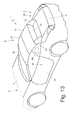
- Figures 13 and 14 show two alternative embodiments of the lateral glasses 30 and of fins 23.
- the lateral glasses 30 have a greater longitudinal development, i.e. the lateral glasses 30 are elongated towards the back, taking an arrow shape (rather than the truncated shape shown in figures 1-12 ).
- fins 23 have a very limited longitudinal extension.
- the openable rigid sun roof 8 described above has many advantages, as it is simple and cost-effective to be implemented and in the folded position it has very limited dimensions.
- the passenger compartment 2 can have a large volume in the rear area thereof (especially in the vertical direction) and thus can also accommodate rear seats, while maintaining well balanced and thus aesthetically pleasing overall proportions of the body.
- the total volume of the baggage compartment 5 is significant (especially when the openable rigid sun roof 8 is in the open position) and definitely much larger than the baggage compartment of a similar conventional car.
- the baggage bonnet 6 can be arranged in a relatively low position (i.e. lower than a similar car with a conventional openable sun roof), thus imparting a vertically slender shape to the rear of car 1 which is aesthetically very much appreciated.
- the movable parts i.e. the roof members 10 and 11
- the openable rigid sun roof 8 described above has a significantly reduced overall weight which can be up to half of the total weight of a similar conventional openable sun roof.
- the transverse dimensions of the roof members 10 and 11 within the baggage compartment 5 is definitely more limited (even by 10-15 cm) than the transversal dimension of a similar conventional openable sun roof and therefore it is possible to have the mudflaps transversely closer to impart a transversely slender and tapered shape to the back of car 1 which is aesthetically very much appreciated.
- the openable rigid sun roof 8 described above has reduced production costs compared to a similar conventional openable sun roof, since the moving parts are definitely less than a similar conventional openable sun roof.
- the openable rigid sun roof 8 described above has a total time of operation (i.e. a time required to change from the closed position to the open position and vice versa) which is certainly short; in fact, the total time of operation of the openable rigid sun roof 8 described above may even be 30-40% less than the total time of operation of a similar conventional openable sun roof.
- the openable rigid sun roof 8 described above is extremely reliable, as it allows the manufacturing defects and the mechanical wear to be minimized thanks to the intrinsically simple structure of the openable rigid sun roof 8.
Landscapes
- Engineering & Computer Science (AREA)
- Mechanical Engineering (AREA)
- Body Structure For Vehicles (AREA)
Abstract
Description
- The present invention relates to a car with an openable rigid sun roof.
- Patent
EP1912815B1 and patentEP2102025B1 describe a car with an openable rigid sun roof, wherein the frame comprises two fixed vertical posts, which are arranged facing each other on opposite sides of the car at a border area between a passenger compartment and a rear engine compartment. The openable rigid sun roof comprises a pair of rigid roof elements which are mechanically connected to the frame by means of respective connecting elements arranged at the inner walls of the two vertical posts. - In cars described in patents
EP1912815B1 andEP2102025B1 , the passenger compartment does not have a particularly large volume in the rear area thereof (especially in the vertical direction) and thus is not able to also accommodate rear seats, maintaining well balanced and thus aesthetically pleasing overall proportions of the body. - The object of the present invention is to provide a car with openable rigid sun roof which allows a particularly spacious passenger compartment (and therefore potentially able to accommodate four seats, two front and two rear) to be obtained while maintaining well balanced and thus aesthetically pleasing overall proportions of the body.
- According to the present invention, a car with openable rigid sun roof is provided according to the appended claims.
- The present invention will now be described with reference to the accompanying drawings, which show some non-limiting embodiment examples thereof, in which:
- ●
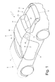
figure 1 is a schematic perspective view of a car with openable rigid sun roof which is made according to the present invention and has the sun roof in a closed position; - ●
figure 2 is a schematic perspective view of the car infigure 1 with the sun roof open; - ●
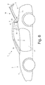
figures 3-7 are a series of schematic and side lateral views of the car infigure 1 during successive steps of the sun roof opening; - •
figure 8 is a schematic lateral view of the car infigure 1 with baggage bonnet open; - •
figure 9 is a schematic rear view of a detail of an external post and an internal post of the frame of the car infigure 1 ; - ●
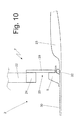
figure 10 is a schematic top view of a detail of the external post and the internal post infigure 9 ; - ●
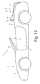
figures 11 and12 are two schematic lateral views of a variant of the car infigure 1 ; and - ●
figures 13 and14 are two schematic perspective views of two further variants of the car infigure 1 . - In
figure 1 ,reference numeral 1 shows a car as a whole having a four-seat (two front and two rear)passenger compartment 2, anengine compartment 3 arranged in the front position (i.e. in front of compartment 2) and closed by anengine bonnet 4, and a baggage compartment 5 (or trunk) arranged in the rear position (i.e. behind compartment 2) and closed by abaggage bonnet 6. A frame 7 (a part whereof is shown infigures 9 and10 ) ofcar 1 supports an openablerigid sun roof 8, which can be arranged in an open position (shown infigures 2 and6-7 ) in which thepassenger compartment 2 is exposed, or in a closed position (shown infigures 1 and3-4 ) in which thepassenger compartment 2 is covered by the openablerigid sun roof 8. - As shown in
figures 8 and9 , frame 7 comprises two vertical fixedexternal posts 9, which are rigidly connected to the remainder of frame 7 in a fixed position (i.e. they have no movement with respect to the remainder of frame 7), vertically project from the belt line ofcar 1 and are arranged facing each other on opposite sides ofcar 1 at a border area between thepassenger compartment 2 and thebaggage compartment 5. - As shown in
figure 1 and2 , the openablerigid sun roof 8 comprises a pair ofrigid roof members 10 and 11 (i.e. the openablerigid sun roof 8 comprises two and only tworigid roof members 10 and 11). Therigid roof members roof members figure 5 , theroof members figure 5 ), which are arranged on opposite sides of theroof members - As shown in the embodiment in
figure 5 , the supporting members of theroof members vertical posts 9. - The
front roof member 10 has arear appendage 13 which is rigidly fixed to thefront roof member 10 and is mechanically connected to the supportingmember 12 by a pair of articulated quadrilaterals 14 (only one of which is shown infigure 5 ) which are arranged on opposite sides of thefront roof member 10 and constitute the supporting members of thefront roof member 10. Moreover, therear roof member 11 is mechanically connected to the supportingmember 12 by a pair of articulated quadrilaterals 15 (only one of which is shown infigure 5 ) which are arranged on opposite sides of therear roof member 11 and constitute the supporting members of therear roof member 11; in particular, each articulated quadrilateral 15 is hinged to arear appendage 13 of thefront roof member 10 and is therefore indirectly connected to the supportingmember 12 through the interposition of therear appendage 13. It is important to note that the method of connection of theroof members roof members rear roof member 11 could be directly connected to the supportingmember 12 by means of respective articulated quadrilaterals which are completely separate and independent from thefront roof member 10, or therear roof member 11 may be hinged to thefront roof member 10; or alternatively, at least a part of the articulated quadrilaterals which determine a rotary-translation movement could be replaced by simple levers which determine a movement of pure rotation. - According to alternative embodiments perfectly equivalent to one another, the supporting members could make the
front roof member 10 carry out a rotation about a fixed axis of rotation, or the supporting members could make thefront roof member 10 carry out a rotary-translation (i.e. a rotation about a mobile axis of rotation). - According to a preferred embodiment, the kinematic mechanisms of the supporting members which carry the
roof members roof members - When the openable
rigid sun roof 8 is arranged in the closed position (shown infigures 1 and3-4 ), the tworoof members rigid sun roof 8 is arranged in the closed position (shown infigures 1 and3-4 ), thefront roof member 10 is arranged in the front position so as to rest the front end thereof in contact with awindshield 16 ofcar 1 and so as to arrange the rear end thereof in contact with the front end of therear roof member 11; moreover, therear roof member 11 is arranged in the rear position so as to have the front end thereof in contact with the end rear of thefront roof member 10 and have the rear end thereof in contact, at the back, with arear window 17 ofcar 1 and with the externalvertical posts 9 of frame 7. - As mentioned above, in the embodiment shown in the accompanying figures, the two
roof members rigid sun roof 8 is arranged in the closed position (figures 1 and3-4 ) and are locked to one another by a dedicated closing system. - When the openable
rigid sun roof 8 is arranged in the open position (shown infigures 2 and6-7 ), the tworoof members movable partition member 18 is provided which divides theluggage compartment 5 so as to establish a physical separation between the area intended to accommodate the tworoof members baggage compartment 5 is closed by acover 19 which is hinged to frame 7 to move between a closed position (shown infigures 1-3 and7 ), in whichcover 19 completely closes thebaggage compartment 5, and an open position (shown infigures 4-6 ), in whichcover 19 is relatively far from thebaggage compartment 5 to allow access to thebaggage compartment 5. According to a preferred, but not limiting, embodiment shown infigure 4 ,cover 19 is supported by a pair of support arms 20 (only one of which is shown infigure 4 ) which are L-shaped and are connected to frame 7 by a pair of articulated quadrilaterals in order to carry out a rotary-translation to move between the closed position (shown infigures 1-3 and7 ) and the open position (shown infigures 4-6 ).Cover 19 supports thebaggage bonnet 6 which is hinged to cover 19; in other words, thebaggage bonnet 6 is integral withcover 19 and moves together withcover 19 whencover 19 is moved between the closed position and the open position.Figure 8 shows an example of the opening movement of thebaggage bonnet 6 which rotates with respect tocover 19 which remains stationary. - In the
baggage compartment 5, the tworoof members figure 6 ); in other words, the tworoof members baggage compartment 5 are vertically packed one on top of the other. According to the preferred, but not limiting, embodiment shown infigure 6 , thebaggage compartment 5 of therear roof member 11 is arranged on thefront roof member 10 and bothroof members roof members baggage compartment 5 is particularly advantageous as it maximizes the volume of thebaggage compartment 5 when the openablerigid sun roof 8 is in the open position (i.e. when theroof members elements - In order to allow the movement of the
roof members baggage compartment 5, therear window 17 is movable parallel to along a substantially vertical direction between an extracted position (shown infigures 1-3 and7 ), in which therear window 17 protrudes from the body, and a withdrawn position (shown infigures 4-6 ) in which therear window 17 is accommodated inside the body in a respective containment tank 21 (schematically shown infigures 3 and9 ) which is formed in asupport structure 22 of the rear window 17 (schematically shown infigures 9 and10 ) arranged between thebaggage compartment 5 and thepassenger compartment 2. In use, therear window 17 is arranged in the withdrawn position both to move the openablerigid sun roof 8 from the closed position to the open position, and to move the openablerigid sun roof 8 from the open position to the closed position, so as to prevent interference with the rotational movement of theroof members - According to a preferred embodiment, the
rear window 17 includes a flat transparent glass, which is arranged substantially vertical (or with suitable inclination to not generate annoying reflections on the inner rearview mirror of car 1) and is supported by two metal brackets slidably mounted on respective guides to move parallel to between the extracted position, in which therear window 17 protrudes from the body, and the withdrawn position in which therear window 17 is accommodated into the body in thecontainment tank 21. - When the openable
rigid sun roof 8 is arranged in the closed position, therear window 17 is generally arranged in the extracted position; however, the driver may decide to arrange therear window 17 in the withdrawn position to increase the ventilation of thepassenger compartment 2. When the openablerigid sun roof 8 is arranged in the open position, therear window 17 is generally arranged in the withdrawn position; however, the driver may decide to arrange therear window 17 in the extracted position to use therear window 17 as windbreak and thereby reduce the turbulence into thepassenger compartment 2. - Preferably,
cover 19 has a pair offins 23, which are arranged on opposite sides ofcover 19 and lay against the externalvertical posts 9 whencover 19 is in a closed position of thebaggage compartment 5. - As shown in
figure 9 ,structure 22 for supporting therear window 17 is supported by two internal fixedvertical posts 24 of frame 7 which constitute the lateral walls of the support structure 22 (in other words, thesupport structure 22 is built on two internalvertical posts 24 which laterally delimit the support structure 22). As shown infigure 8 , the two internalvertical posts 24 are arranged between the externalvertical posts 9 and at a given distance from the external vertical posts, so as to define, between each externalvertical post 9 and the corresponding internalvertical post 24, ahollow space 25, that is, a technical space intended to accommodate functional parts of the openablerigid sun roof 8. Also the internalvertical posts 24 are rigidly connected to the remainder of frame 7 in a fixed position (i.e. they have no kind of movement with respect to the remainder of frame 7). - According to a preferred embodiment, the support organs of the
roof members hollow spaces 25; therefore, in the embodiment shown in the accompanying figures,arms 14 of thefront roof member 10 are arranged in the twohollow spaces 25 which in turn support the articulatedquadrilaterals 15 of therear roof member 11. As shown infigure 8 , each pair ofvertical posts 9 and 24 (i.e. each pair consisting of an externalvertical post 9 and of the corresponding internal vertical post 24) comprises astructural connection 26 which is arranged vertically and is connected at the ends thereof to the twovertical posts 9 and 24 (for example, but not necessarily, by means of screws 27). Eachstructural connection 26 has both the structural function of strengthening this area of frame 7 (in other words, thanks to thestructural connection 26, the correspondingvertical posts bearing member 12 which supports theroof members - When the openable
rigid sun roof 8 is in the closed position, therear roof member 11 superiorly covers thehollow spaces 25 and rests with the interposition of seals on anupper wall 28 of each externalvertical post 9 of frame 7 and on anupper wall 29 of each internalvertical post 24 of frame 7. - As shown in
figure 8 , the externalvertical posts 9 and the internalvertical posts 24 can also together carry out the function of roll-bar in the event of overturning ofcar 1. In particular, the internalvertical posts 24 are higher than the external vertical posts 9 (i.e. theupper walls 29 of the internalvertical posts 24 are arranged higher than theupper walls 28 of the external vertical posts 9); in this way, in case of overturning ofcar 1, the externalvertical posts 9 primarily have the function of transversal roll-bar (i.e. they laterally protect the occupants of the passenger compartment 2) and the internalvertical posts 24 primarily have the function of vertical roll-bar (i.e. they superiorly protect the occupants of the passenger compartment 2). Thestructural connections 26, by connecting thevertical posts vertical posts - Thanks to the fact that the external
vertical posts 9 are arranged more outwards of the seats, the structure composed of thevertical posts - As shown in
figures 1-7 , a pair oflateral glasses 30 is provided, which project from the belt line ofcar 1, are arranged facing each other on opposite sides ofcar 1, lay posteriorly (i.e. at a rear area) and transversely (i.e. in a transverse direction, i.e. lateral) on the corresponding externalvertical posts 9 and constitute a lateral delimitation of thepassenger compartment 2. In the practice, and as clearly shown infigure 10 , eachlateral glass 30 lays transversely (laterally) on the corresponding externalvertical post 9 and develops along the side ofcar 1 to laterally delimit thepassenger compartment 2 in the vicinity of the rear window 17 (that is, in the vicinity of the two external vertical posts 9). Preferably, a lateral internal surface (that is, directed towards compartment 2) of eachlateral glass 30 is arranged in contact with an external lateral surface of the corresponding externalvertical post 9; in other words, eachlateral glass 30 laterally covers the corresponding externalvertical post 9 so that the externalvertical post 9 is laterally hidden from view by thelateral glass 30. - According to a preferred embodiment shown in the accompanying figures, each
lateral glass 30 is transparent, or is made of a transparent material which may be glass or plastic (polycarbonate). - When the openable
rigid sun roof 8 is arranged in the closed position (shown infigures 1 and3-4 ), therear roof member 10, on the rear side, lays against an upper edge of therear window 17 and on theupper walls 28 of the externalvertical posts 9 and laterally lays on upper walls of thelateral glasses 30. - According to a preferred embodiment, two (and only two)
doors 31 are provided, which allow access to thepassenger compartment 2, and two side windows, each of which is mounted vertically movable in acorresponding door 31 and posteriorly and slidably lays against alateral glass 30. In other words, eachlateral glass 30 is frontally provided with a guide along which a corresponding window carried by adoor 31 slides. Accordingly, the twoglasses 30 are arranged staggered and longitudinally more backwards with respect todoors 31 so that below eachglass 30 there is a fixed part (i.e. not openable) of the body. - According to a possible embodiment shown in
figures 1-7 , eachlateral glass 30 is fixed and is rigidly and permanently connected to the corresponding externalvertical post 9; in other words, eachlateral glass 30 has no movement and always remains in the position shown infigures 1-7 . In this embodiment, eachlateral glass 30 is carried by an annular frame which runs all around thelateral glass 30, is rigidly fixed to frame 7, and is hidden to view by a silkscreen printing printed on the lateral glass 30 (clearly visible infigures 1-7 ). According to a different embodiment shown infigures 11 and12 , eachlateral glass 30 is mounted in a mobile manner so as to vertically slide between an extracted position (shown infigure 11 ), in which thelateral glass 30 projects from the belt line ofcar 1, and a withdrawn position (shown infigure 12 ), in which thelateral glass 30 is hidden under the belt line ofcar 1. In this embodiment, eachlateral glass 30 on the rear side lays against the corresponding externalvertical post 9 in a sliding manner. Furthermore, in this embodiment, eachlateral glass 30 has no frame and therefore corresponding silkscreen printing; i.e. in this embodiment eachlateral glass 30 is completely transparent in all its parts. - According to a preferred embodiment shown in
figure 10 , each externalvertical post 9 is provided with aseal 32 which is interposed between the externalvertical post 9 and the correspondingfin 23 whenfin 23 lays against the externalvertical post 9; the function ofseals 32 is to seal the contact between the externalvertical posts 9 andfins 23 to prevent water infiltration. -
Figures 13 and14 show two alternative embodiments of thelateral glasses 30 and offins 23. In the embodiment shown infigure 13 , thelateral glasses 30 have a greater longitudinal development, i.e. thelateral glasses 30 are elongated towards the back, taking an arrow shape (rather than the truncated shape shown infigures 1-12 ). In the embodiment shown infigure 14 ,fins 23 have a very limited longitudinal extension. - The openable
rigid sun roof 8 described above has many advantages, as it is simple and cost-effective to be implemented and in the folded position it has very limited dimensions. - Moreover, thanks to the openable
rigid sun roof 8 described above, thepassenger compartment 2 can have a large volume in the rear area thereof (especially in the vertical direction) and thus can also accommodate rear seats, while maintaining well balanced and thus aesthetically pleasing overall proportions of the body. - The total volume of the
baggage compartment 5 is significant (especially when the openablerigid sun roof 8 is in the open position) and definitely much larger than the baggage compartment of a similar conventional car. In this way, thebaggage bonnet 6 can be arranged in a relatively low position (i.e. lower than a similar car with a conventional openable sun roof), thus imparting a vertically slender shape to the rear ofcar 1 which is aesthetically very much appreciated. - In the openable
rigid sun roof 8 described above, the movable parts (i.e. theroof members 10 and 11) are much smaller (especially narrower) than a similar conventional sun roof; in this way, the openablerigid sun roof 8 described above has a significantly reduced overall weight which can be up to half of the total weight of a similar conventional openable sun roof. Moreover, in this way, the transverse dimensions of theroof members baggage compartment 5 is definitely more limited (even by 10-15 cm) than the transversal dimension of a similar conventional openable sun roof and therefore it is possible to have the mudflaps transversely closer to impart a transversely slender and tapered shape to the back ofcar 1 which is aesthetically very much appreciated. - The openable
rigid sun roof 8 described above has reduced production costs compared to a similar conventional openable sun roof, since the moving parts are definitely less than a similar conventional openable sun roof. - The openable
rigid sun roof 8 described above has a total time of operation (i.e. a time required to change from the closed position to the open position and vice versa) which is certainly short; in fact, the total time of operation of the openablerigid sun roof 8 described above may even be 30-40% less than the total time of operation of a similar conventional openable sun roof. - Finally, the openable
rigid sun roof 8 described above is extremely reliable, as it allows the manufacturing defects and the mechanical wear to be minimized thanks to the intrinsically simple structure of the openablerigid sun roof 8.
Claims (9)
- A car (1) comprising:a passenger compartment (2);two doors (31) which allow access to the passenger compartment (2) and are provided with respective lateral windows, each of which is vertically movably mounted in a corresponding door (31);a frame (7) provided with two external fixed vertical posts (9), which are rigidly connected to the remainder of the frame (7) in a fixed position, project from the belt line of the car (1), face each other on opposite sides of the car (1), and build a rear delimitation of the passenger compartment (2);a rigid sun roof (8), which is supported by the frame (7) and can be set to an open position or a closed position with respect to the passenger compartment (2);a baggage compartment (5), which is arranged in a rear position and contains the rigid sun roof (8), when the rigid sun roof (8) is arranged in the open position;a mobile cover (19) to close the baggage compartment (5); anda rear window (17), which is arranged between the two external vertical posts (9) and is mounted in a sliding manner so as to move between an extracted position, in which the rear window (17) projects from the car body, and a withdrawn position, in which the rear window (17) is housed inside the car body;wherein the rigid sun roof (8) comprises two rigid roof members (10, 11) which, when the rigid sun roof (8) is in the closed position, are substantially horizontal and substantially coplanar to each other so as to be seamlessly positioned one behind the other, and, when the rigid sun roof (8) is in the open position, are packed one on top of the other inside the baggage compartment (5); andwherein the roof members (10, 11) are fitted to the frame (7) by means of corresponding support organs, which are arranged on opposite sides of the roof members (10, 11);the car (1) is characterised in that it comprises a pair of lateral glasses (30), which:a) are arranged longitudinally more rearwards with respect to the doors (31) so that underneath each glass (30) there is a fixed part of the body,b) are separate and independent from the lateral windows of the doors (31) and frontally and slidably lay on the corresponding lateral windows,c) project from the belt line of the car (1) and face each other on opposite sides of the car (1), for forming a lateral delimitation of the passenger compartment (2),d) transversally lay against the corresponding external vertical posts (9), and a lateral internal surface of each lateral glass (30) is arranged in contact with an external lateral surface of the corresponding external vertical post (9) so that each lateral glass (30) laterally covers the corresponding external vertical post (9).
- A car (1) according to claim 1, wherein, when the openable rigid sun roof (8) is arranged in the closed position, the rear roof element (10), on the rear side, lays against an upper edge of the rear window (17) and on upper walls (28) of the external vertical posts (9) and laterally lays on upper walls of the lateral glasses (30).
- A car (1) according to claim 1 or 2, wherein each lateral glass (30) builds a continuation of the corresponding external vertical post (9), which develops along the side of the car (1) so as to laterally delimit the passenger compartment (2) close to the rear window (17).
- A car (1) according to claim 1, 2 or 3, wherein the lateral glass (30) is transparent.
- A car (1) according to any of the claims from 1 to 4, wherein each lateral glass (30) is fixed as well as rigidly and permanently connected to the corresponding external vertical post (9).
- A car (1) according to any of the claims from 1 to 4, wherein each lateral glass (30) is mounted in a mobile manner so as to vertically slide between an extracted position, in which the lateral glass (30) projects from the belt line, and a withdrawn position, in which the lateral glass (30) is hidden under the belt line.
- A car (1) according to claim 6, wherein each lateral glass (30), on the rear side, lays against the corresponding external vertical post (9) in a sliding manner.
- A car (1) according to any of the claims from 1 to 7, wherein a bonnet (6), which allows access to the baggage compartment (5), is hinged to the cover (19) and moves, together with the cover (19), when the cover (19) is moved.
- A car (1) according to any of the claims from 1 to 8, wherein the frame (7) comprises two internal fixed vertical posts (24), which are arranged between the external vertical posts (9) at a given distance from the external vertical posts (9), so as to define, between each external vertical post (9) and the corresponding internal vertical post (24), a hollow space (25), in which the support organs of the roof members (10, 11) are arranged.
Applications Claiming Priority (1)
| Application Number | Priority Date | Filing Date | Title |
|---|---|---|---|
| IT000137A ITBO20130137A1 (en) | 2013-03-29 | 2013-03-29 | CAR WITH RIGID OPENING ROOF, PREFERABLY WITH FOUR PLACES |
Publications (2)
| Publication Number | Publication Date |
|---|---|
| EP2783887A1 true EP2783887A1 (en) | 2014-10-01 |
| EP2783887B1 EP2783887B1 (en) | 2016-05-18 |
Family
ID=48485255
Family Applications (1)
| Application Number | Title | Priority Date | Filing Date |
|---|---|---|---|
| EP14162515.2A Active EP2783887B1 (en) | 2013-03-29 | 2014-03-28 | Cabriolet with hard top, having preferably four seats |
Country Status (3)
| Country | Link |
|---|---|
| US (1) | US9186969B2 (en) |
| EP (1) | EP2783887B1 (en) |
| IT (1) | ITBO20130137A1 (en) |
Families Citing this family (10)
| Publication number | Priority date | Publication date | Assignee | Title |
|---|---|---|---|---|
| US9561711B2 (en) | 2014-03-19 | 2017-02-07 | Ferrari S.P.A. | Convertible car with a rigid sunroof and a front engine and corresponding control method |
| DE102015010338B4 (en) * | 2014-09-26 | 2018-10-31 | Mazda Motor Corporation | Rear vehicle body structure of a vehicle |
| JP6295935B2 (en) * | 2014-12-08 | 2018-03-20 | マツダ株式会社 | Body structure of an open / close roof car |
| JP6295934B2 (en) * | 2014-12-08 | 2018-03-20 | マツダ株式会社 | Body structure of an open / close roof car |
| JP6295945B2 (en) * | 2014-12-22 | 2018-03-20 | マツダ株式会社 | Body structure of an open / close roof car |
| RO130500A0 (en) * | 2015-04-27 | 2015-08-28 | Daniel Vîlcelaru | Method of making collapse the roof of convertible cars provided with rigid roof |
| US10272753B1 (en) * | 2016-01-20 | 2019-04-30 | Apple Inc. | Sliding panel assembly |
| JP6315012B2 (en) * | 2016-03-18 | 2018-04-25 | マツダ株式会社 | Rear body structure of a car with retractable roof |
| GB2553111B (en) | 2016-08-22 | 2021-08-11 | Mclaren Automotive Ltd | Vehicle upper structure |
| US20260103249A1 (en) | 2024-06-26 | 2026-04-16 | Ferrari S.P.A. | Control system and control method for a moveable wing assembly and a convertible roof assembly of a convertible road vehicle and related road vehicle |
Citations (10)
| Publication number | Priority date | Publication date | Assignee | Title |
|---|---|---|---|---|
| EP0845378A1 (en) * | 1996-11-30 | 1998-06-03 | CTS Fahrzeug-Dachsysteme GmbH | Vehicle roof structure, especially for passenger vehicles |
| DE19738281A1 (en) * | 1997-09-02 | 1999-03-11 | Audi Ag | Private pickup vehicle |
| DE19752068A1 (en) * | 1997-11-25 | 1999-05-27 | Porsche Ag | Roof structure for vehicle |
| DE102004005591A1 (en) * | 2004-02-04 | 2005-08-25 | Wilhelm Karmann Gmbh | Cabriolet vehicle with a rollover protection system |
| DE102005004531A1 (en) * | 2005-01-31 | 2006-08-10 | Webasto Ag | Vehicle with a convertible roof |
| EP1728707A2 (en) * | 2005-06-01 | 2006-12-06 | Dr.Ing. h.c.F. Porsche Aktiengesellschaft | Passenger compartment of a motor vehicle |
| EP1882605A1 (en) * | 2006-07-29 | 2008-01-30 | GM Global Technology Operations, Inc. | Convertible vehicle body |
| DE102008021508A1 (en) * | 2008-04-30 | 2009-11-05 | Magna Car Top Systems Gmbh | Moving roof for vehicle, particularly passenger vehicle, has multiple roof elements provided in vehicle longitudinal direction, moved between closing position and opening position, and is lowered in storage chamber |
| EP1912815B1 (en) | 2005-07-22 | 2010-03-03 | FERRARI S.p.A. | Car with a sun roof |
| DE102009034641A1 (en) * | 2009-07-24 | 2011-02-03 | Dr. Ing. H.C. F. Porsche Aktiengesellschaft | Open passenger car, has protection element arranged below rear element in resting position, and rear element comprising rear window that is penetrated into protection position of protection element |
Family Cites Families (3)
| Publication number | Priority date | Publication date | Assignee | Title |
|---|---|---|---|---|
| DE10345123A1 (en) * | 2003-09-26 | 2005-06-02 | Cts Fahrzeug-Dachsysteme Gmbh | Convertible has C-pillars at rear which are linked at top by cross-bar and form roll-bar when car roof is open |
| DE102005002935A1 (en) * | 2005-01-21 | 2006-07-27 | Wilhelm Karmann Gmbh | Motor vehicle e.g. cabriolet, has rear roof unit held on rear side of vehicle body and movable downward about rear sided linkage below apron wall line, and front roof units stored out of range of rear units |
| ITBO20110478A1 (en) * | 2011-08-01 | 2013-02-02 | Ferrari Spa | CAR WITH AN OPENABLE ROOF PROVIDED WITH A REAR WINDOW CONTAINMENT TANK |
-
2013
- 2013-03-29 IT IT000137A patent/ITBO20130137A1/en unknown
-
2014
- 2014-03-28 EP EP14162515.2A patent/EP2783887B1/en active Active
- 2014-03-28 US US14/228,943 patent/US9186969B2/en active Active
Patent Citations (11)
| Publication number | Priority date | Publication date | Assignee | Title |
|---|---|---|---|---|
| EP0845378A1 (en) * | 1996-11-30 | 1998-06-03 | CTS Fahrzeug-Dachsysteme GmbH | Vehicle roof structure, especially for passenger vehicles |
| DE19738281A1 (en) * | 1997-09-02 | 1999-03-11 | Audi Ag | Private pickup vehicle |
| DE19752068A1 (en) * | 1997-11-25 | 1999-05-27 | Porsche Ag | Roof structure for vehicle |
| DE102004005591A1 (en) * | 2004-02-04 | 2005-08-25 | Wilhelm Karmann Gmbh | Cabriolet vehicle with a rollover protection system |
| DE102005004531A1 (en) * | 2005-01-31 | 2006-08-10 | Webasto Ag | Vehicle with a convertible roof |
| EP2102025B1 (en) | 2005-01-31 | 2010-05-05 | Webasto AG | Convertible roof motor vehicle |
| EP1728707A2 (en) * | 2005-06-01 | 2006-12-06 | Dr.Ing. h.c.F. Porsche Aktiengesellschaft | Passenger compartment of a motor vehicle |
| EP1912815B1 (en) | 2005-07-22 | 2010-03-03 | FERRARI S.p.A. | Car with a sun roof |
| EP1882605A1 (en) * | 2006-07-29 | 2008-01-30 | GM Global Technology Operations, Inc. | Convertible vehicle body |
| DE102008021508A1 (en) * | 2008-04-30 | 2009-11-05 | Magna Car Top Systems Gmbh | Moving roof for vehicle, particularly passenger vehicle, has multiple roof elements provided in vehicle longitudinal direction, moved between closing position and opening position, and is lowered in storage chamber |
| DE102009034641A1 (en) * | 2009-07-24 | 2011-02-03 | Dr. Ing. H.C. F. Porsche Aktiengesellschaft | Open passenger car, has protection element arranged below rear element in resting position, and rear element comprising rear window that is penetrated into protection position of protection element |
Also Published As
| Publication number | Publication date |
|---|---|
| US20140292019A1 (en) | 2014-10-02 |
| EP2783887B1 (en) | 2016-05-18 |
| US9186969B2 (en) | 2015-11-17 |
| ITBO20130137A1 (en) | 2014-09-30 |
Similar Documents
| Publication | Publication Date | Title |
|---|---|---|
| EP2783887B1 (en) | Cabriolet with hard top, having preferably four seats | |
| EP2554417B1 (en) | Car with a sun roof provided with closing bodies and hollow spaces | |
| CN101516661B (en) | Roof system with struts | |
| US20020024231A1 (en) | Convertible vehicle roof and convertible vehicle | |
| CN101495336B (en) | Convertible vehicle body | |
| EP2554416B1 (en) | Car with a sun roof provided with internal and external vertical posts | |
| US8454077B2 (en) | Headerless opposing hinged doors | |
| EP1136295B1 (en) | Tonneau cover for covering the boot of a convertible, and a convertible | |
| US8205929B2 (en) | Car with a sun roof | |
| US8567845B2 (en) | Car with a sun roof provided with a containing tank of the rear window | |
| ITRM990363A1 (en) | VEHICLE WITH OPENABLE CAPOTE. | |
| US7100963B2 (en) | Roof retractable into the rear trunk of a vehicle, and including movable side elements | |
| JP4831376B2 (en) | Hard top folding roof for open car | |
| EP2554419B1 (en) | Car with a sun roof provided with sealing gaskets | |
| EP1817191B1 (en) | Openable roof system for a motor car | |
| EP1882606B1 (en) | Convertible vehicle body | |
| US6447056B1 (en) | Vehicle having an open roof construction and such open roof construction |
Legal Events
| Date | Code | Title | Description |
|---|---|---|---|
| 17P | Request for examination filed |
Effective date: 20140328 |
|
| AK | Designated contracting states |
Kind code of ref document: A1 Designated state(s): AL AT BE BG CH CY CZ DE DK EE ES FI FR GB GR HR HU IE IS IT LI LT LU LV MC MK MT NL NO PL PT RO RS SE SI SK SM TR |
|
| AX | Request for extension of the european patent |
Extension state: BA ME |
|
| PUAI | Public reference made under article 153(3) epc to a published international application that has entered the european phase |
Free format text: ORIGINAL CODE: 0009012 |
|
| R17P | Request for examination filed (corrected) |
Effective date: 20140926 |
|
| RBV | Designated contracting states (corrected) |
Designated state(s): AL AT BE BG CH CY CZ DE DK EE ES FI FR GB GR HR HU IE IS IT LI LT LU LV MC MK MT NL NO PL PT RO RS SE SI SK SM TR |
|
| GRAP | Despatch of communication of intention to grant a patent |
Free format text: ORIGINAL CODE: EPIDOSNIGR1 |
|
| RIC1 | Information provided on ipc code assigned before grant |
Ipc: B60J 7/20 20060101ALI20151023BHEP Ipc: B60J 7/14 20060101ALI20151023BHEP Ipc: B60J 1/17 20060101ALI20151023BHEP Ipc: B60J 1/18 20060101AFI20151023BHEP Ipc: B60J 1/10 20060101ALI20151023BHEP |
|
| INTG | Intention to grant announced |
Effective date: 20151113 |
|
| GRAS | Grant fee paid |
Free format text: ORIGINAL CODE: EPIDOSNIGR3 |
|
| GRAA | (expected) grant |
Free format text: ORIGINAL CODE: 0009210 |
|
| AK | Designated contracting states |
Kind code of ref document: B1 Designated state(s): AL AT BE BG CH CY CZ DE DK EE ES FI FR GB GR HR HU IE IS IT LI LT LU LV MC MK MT NL NO PL PT RO RS SE SI SK SM TR |
|
| REG | Reference to a national code |
Ref country code: GB Ref legal event code: FG4D |
|
| REG | Reference to a national code |
Ref country code: CH Ref legal event code: EP |
|
| REG | Reference to a national code |
Ref country code: IE Ref legal event code: FG4D Ref country code: AT Ref legal event code: REF Ref document number: 800109 Country of ref document: AT Kind code of ref document: T Effective date: 20160615 |
|
| REG | Reference to a national code |
Ref country code: DE Ref legal event code: R096 Ref document number: 602014001940 Country of ref document: DE |
|
| REG | Reference to a national code |
Ref country code: NL Ref legal event code: MP Effective date: 20160518 |
|
| REG | Reference to a national code |
Ref country code: LT Ref legal event code: MG4D |
|
| PG25 | Lapsed in a contracting state [announced via postgrant information from national office to epo] |
Ref country code: NL Free format text: LAPSE BECAUSE OF FAILURE TO SUBMIT A TRANSLATION OF THE DESCRIPTION OR TO PAY THE FEE WITHIN THE PRESCRIBED TIME-LIMIT Effective date: 20160518 Ref country code: NO Free format text: LAPSE BECAUSE OF FAILURE TO SUBMIT A TRANSLATION OF THE DESCRIPTION OR TO PAY THE FEE WITHIN THE PRESCRIBED TIME-LIMIT Effective date: 20160818 Ref country code: FI Free format text: LAPSE BECAUSE OF FAILURE TO SUBMIT A TRANSLATION OF THE DESCRIPTION OR TO PAY THE FEE WITHIN THE PRESCRIBED TIME-LIMIT Effective date: 20160518 Ref country code: LT Free format text: LAPSE BECAUSE OF FAILURE TO SUBMIT A TRANSLATION OF THE DESCRIPTION OR TO PAY THE FEE WITHIN THE PRESCRIBED TIME-LIMIT Effective date: 20160518 |
|
| REG | Reference to a national code |
Ref country code: AT Ref legal event code: MK05 Ref document number: 800109 Country of ref document: AT Kind code of ref document: T Effective date: 20160518 |
|
| PG25 | Lapsed in a contracting state [announced via postgrant information from national office to epo] |
Ref country code: ES Free format text: LAPSE BECAUSE OF FAILURE TO SUBMIT A TRANSLATION OF THE DESCRIPTION OR TO PAY THE FEE WITHIN THE PRESCRIBED TIME-LIMIT Effective date: 20160518 Ref country code: HR Free format text: LAPSE BECAUSE OF FAILURE TO SUBMIT A TRANSLATION OF THE DESCRIPTION OR TO PAY THE FEE WITHIN THE PRESCRIBED TIME-LIMIT Effective date: 20160518 Ref country code: SE Free format text: LAPSE BECAUSE OF FAILURE TO SUBMIT A TRANSLATION OF THE DESCRIPTION OR TO PAY THE FEE WITHIN THE PRESCRIBED TIME-LIMIT Effective date: 20160518 Ref country code: RS Free format text: LAPSE BECAUSE OF FAILURE TO SUBMIT A TRANSLATION OF THE DESCRIPTION OR TO PAY THE FEE WITHIN THE PRESCRIBED TIME-LIMIT Effective date: 20160518 Ref country code: GR Free format text: LAPSE BECAUSE OF FAILURE TO SUBMIT A TRANSLATION OF THE DESCRIPTION OR TO PAY THE FEE WITHIN THE PRESCRIBED TIME-LIMIT Effective date: 20160819 Ref country code: LV Free format text: LAPSE BECAUSE OF FAILURE TO SUBMIT A TRANSLATION OF THE DESCRIPTION OR TO PAY THE FEE WITHIN THE PRESCRIBED TIME-LIMIT Effective date: 20160518 Ref country code: PT Free format text: LAPSE BECAUSE OF FAILURE TO SUBMIT A TRANSLATION OF THE DESCRIPTION OR TO PAY THE FEE WITHIN THE PRESCRIBED TIME-LIMIT Effective date: 20160919 |
|
| PG25 | Lapsed in a contracting state [announced via postgrant information from national office to epo] |
Ref country code: SK Free format text: LAPSE BECAUSE OF FAILURE TO SUBMIT A TRANSLATION OF THE DESCRIPTION OR TO PAY THE FEE WITHIN THE PRESCRIBED TIME-LIMIT Effective date: 20160518 Ref country code: DK Free format text: LAPSE BECAUSE OF FAILURE TO SUBMIT A TRANSLATION OF THE DESCRIPTION OR TO PAY THE FEE WITHIN THE PRESCRIBED TIME-LIMIT Effective date: 20160518 Ref country code: RO Free format text: LAPSE BECAUSE OF FAILURE TO SUBMIT A TRANSLATION OF THE DESCRIPTION OR TO PAY THE FEE WITHIN THE PRESCRIBED TIME-LIMIT Effective date: 20160518 Ref country code: CZ Free format text: LAPSE BECAUSE OF FAILURE TO SUBMIT A TRANSLATION OF THE DESCRIPTION OR TO PAY THE FEE WITHIN THE PRESCRIBED TIME-LIMIT Effective date: 20160518 Ref country code: EE Free format text: LAPSE BECAUSE OF FAILURE TO SUBMIT A TRANSLATION OF THE DESCRIPTION OR TO PAY THE FEE WITHIN THE PRESCRIBED TIME-LIMIT Effective date: 20160518 |
|
| REG | Reference to a national code |
Ref country code: DE Ref legal event code: R097 Ref document number: 602014001940 Country of ref document: DE |
|
| PG25 | Lapsed in a contracting state [announced via postgrant information from national office to epo] |
Ref country code: SM Free format text: LAPSE BECAUSE OF FAILURE TO SUBMIT A TRANSLATION OF THE DESCRIPTION OR TO PAY THE FEE WITHIN THE PRESCRIBED TIME-LIMIT Effective date: 20160518 Ref country code: AT Free format text: LAPSE BECAUSE OF FAILURE TO SUBMIT A TRANSLATION OF THE DESCRIPTION OR TO PAY THE FEE WITHIN THE PRESCRIBED TIME-LIMIT Effective date: 20160518 Ref country code: BE Free format text: LAPSE BECAUSE OF FAILURE TO SUBMIT A TRANSLATION OF THE DESCRIPTION OR TO PAY THE FEE WITHIN THE PRESCRIBED TIME-LIMIT Effective date: 20160518 Ref country code: PL Free format text: LAPSE BECAUSE OF FAILURE TO SUBMIT A TRANSLATION OF THE DESCRIPTION OR TO PAY THE FEE WITHIN THE PRESCRIBED TIME-LIMIT Effective date: 20160518 |
|
| PLBE | No opposition filed within time limit |
Free format text: ORIGINAL CODE: 0009261 |
|
| STAA | Information on the status of an ep patent application or granted ep patent |
Free format text: STATUS: NO OPPOSITION FILED WITHIN TIME LIMIT |
|
| 26N | No opposition filed |
Effective date: 20170221 |
|
| PG25 | Lapsed in a contracting state [announced via postgrant information from national office to epo] |
Ref country code: SI Free format text: LAPSE BECAUSE OF FAILURE TO SUBMIT A TRANSLATION OF THE DESCRIPTION OR TO PAY THE FEE WITHIN THE PRESCRIBED TIME-LIMIT Effective date: 20160518 |
|
| REG | Reference to a national code |
Ref country code: CH Ref legal event code: PL |
|
| PG25 | Lapsed in a contracting state [announced via postgrant information from national office to epo] |
Ref country code: MC Free format text: LAPSE BECAUSE OF FAILURE TO SUBMIT A TRANSLATION OF THE DESCRIPTION OR TO PAY THE FEE WITHIN THE PRESCRIBED TIME-LIMIT Effective date: 20160518 |
|
| REG | Reference to a national code |
Ref country code: IE Ref legal event code: MM4A |
|
| REG | Reference to a national code |
Ref country code: FR Ref legal event code: ST Effective date: 20171130 |
|
| PG25 | Lapsed in a contracting state [announced via postgrant information from national office to epo] |
Ref country code: FR Free format text: LAPSE BECAUSE OF NON-PAYMENT OF DUE FEES Effective date: 20170331 Ref country code: LU Free format text: LAPSE BECAUSE OF NON-PAYMENT OF DUE FEES Effective date: 20170328 |
|
| PG25 | Lapsed in a contracting state [announced via postgrant information from national office to epo] |
Ref country code: CH Free format text: LAPSE BECAUSE OF NON-PAYMENT OF DUE FEES Effective date: 20170331 Ref country code: LI Free format text: LAPSE BECAUSE OF NON-PAYMENT OF DUE FEES Effective date: 20170331 Ref country code: IE Free format text: LAPSE BECAUSE OF NON-PAYMENT OF DUE FEES Effective date: 20170328 |
|
| PG25 | Lapsed in a contracting state [announced via postgrant information from national office to epo] |
Ref country code: MT Free format text: LAPSE BECAUSE OF NON-PAYMENT OF DUE FEES Effective date: 20170328 |
|
| PG25 | Lapsed in a contracting state [announced via postgrant information from national office to epo] |
Ref country code: AL Free format text: LAPSE BECAUSE OF FAILURE TO SUBMIT A TRANSLATION OF THE DESCRIPTION OR TO PAY THE FEE WITHIN THE PRESCRIBED TIME-LIMIT Effective date: 20160518 |
|
| PG25 | Lapsed in a contracting state [announced via postgrant information from national office to epo] |
Ref country code: HU Free format text: LAPSE BECAUSE OF FAILURE TO SUBMIT A TRANSLATION OF THE DESCRIPTION OR TO PAY THE FEE WITHIN THE PRESCRIBED TIME-LIMIT; INVALID AB INITIO Effective date: 20140328 |
|
| PG25 | Lapsed in a contracting state [announced via postgrant information from national office to epo] |
Ref country code: BG Free format text: LAPSE BECAUSE OF FAILURE TO SUBMIT A TRANSLATION OF THE DESCRIPTION OR TO PAY THE FEE WITHIN THE PRESCRIBED TIME-LIMIT Effective date: 20160518 |
|
| PG25 | Lapsed in a contracting state [announced via postgrant information from national office to epo] |
Ref country code: CY Free format text: LAPSE BECAUSE OF FAILURE TO SUBMIT A TRANSLATION OF THE DESCRIPTION OR TO PAY THE FEE WITHIN THE PRESCRIBED TIME-LIMIT Effective date: 20160518 |
|
| PG25 | Lapsed in a contracting state [announced via postgrant information from national office to epo] |
Ref country code: MK Free format text: LAPSE BECAUSE OF FAILURE TO SUBMIT A TRANSLATION OF THE DESCRIPTION OR TO PAY THE FEE WITHIN THE PRESCRIBED TIME-LIMIT Effective date: 20160518 |
|
| PG25 | Lapsed in a contracting state [announced via postgrant information from national office to epo] |
Ref country code: TR Free format text: LAPSE BECAUSE OF FAILURE TO SUBMIT A TRANSLATION OF THE DESCRIPTION OR TO PAY THE FEE WITHIN THE PRESCRIBED TIME-LIMIT Effective date: 20160518 |
|
| PG25 | Lapsed in a contracting state [announced via postgrant information from national office to epo] |
Ref country code: IS Free format text: LAPSE BECAUSE OF FAILURE TO SUBMIT A TRANSLATION OF THE DESCRIPTION OR TO PAY THE FEE WITHIN THE PRESCRIBED TIME-LIMIT Effective date: 20160918 |
|
| P01 | Opt-out of the competence of the unified patent court (upc) registered |
Effective date: 20230525 |
|
| PGFP | Annual fee paid to national office [announced via postgrant information from national office to epo] |
Ref country code: GB Payment date: 20260122 Year of fee payment: 13 |
|
| PGFP | Annual fee paid to national office [announced via postgrant information from national office to epo] |
Ref country code: DE Payment date: 20260320 Year of fee payment: 13 |
|
| PGFP | Annual fee paid to national office [announced via postgrant information from national office to epo] |
Ref country code: IT Payment date: 20260310 Year of fee payment: 13 |