EP2783872B1 - Printing apparatus and printing method - Google Patents
Printing apparatus and printing method Download PDFInfo
- Publication number
- EP2783872B1 EP2783872B1 EP14160676.4A EP14160676A EP2783872B1 EP 2783872 B1 EP2783872 B1 EP 2783872B1 EP 14160676 A EP14160676 A EP 14160676A EP 2783872 B1 EP2783872 B1 EP 2783872B1
- Authority
- EP
- European Patent Office
- Prior art keywords
- sheet
- recording medium
- rotating shaft
- support member
- print head
- Prior art date
- Legal status (The legal status is an assumption and is not a legal conclusion. Google has not performed a legal analysis and makes no representation as to the accuracy of the status listed.)
- Active
Links
Images


Classifications
-
- B—PERFORMING OPERATIONS; TRANSPORTING
- B41—PRINTING; LINING MACHINES; TYPEWRITERS; STAMPS
- B41J—TYPEWRITERS; SELECTIVE PRINTING MECHANISMS, i.e. MECHANISMS PRINTING OTHERWISE THAN FROM A FORME; CORRECTION OF TYPOGRAPHICAL ERRORS
- B41J15/00—Devices or arrangements of selective printing mechanisms, e.g. ink-jet printers or thermal printers, specially adapted for supporting or handling copy material in continuous form, e.g. webs
- B41J15/04—Supporting, feeding, or guiding devices; Mountings for web rolls or spindles
-
- B—PERFORMING OPERATIONS; TRANSPORTING
- B41—PRINTING; LINING MACHINES; TYPEWRITERS; STAMPS
- B41J—TYPEWRITERS; SELECTIVE PRINTING MECHANISMS, i.e. MECHANISMS PRINTING OTHERWISE THAN FROM A FORME; CORRECTION OF TYPOGRAPHICAL ERRORS
- B41J11/00—Devices or arrangements of selective printing mechanisms, e.g. ink-jet printers or thermal printers, for supporting or handling copy material in sheet or web form
- B41J11/0015—Devices or arrangements of selective printing mechanisms, e.g. ink-jet printers or thermal printers, for supporting or handling copy material in sheet or web form for treating before, during or after printing or for uniform coating or laminating the copy material before or after printing
-
- B—PERFORMING OPERATIONS; TRANSPORTING
- B41—PRINTING; LINING MACHINES; TYPEWRITERS; STAMPS
- B41J—TYPEWRITERS; SELECTIVE PRINTING MECHANISMS, i.e. MECHANISMS PRINTING OTHERWISE THAN FROM A FORME; CORRECTION OF TYPOGRAPHICAL ERRORS
- B41J13/00—Devices or arrangements of selective printing mechanisms, e.g. ink-jet printers or thermal printers, specially adapted for supporting or handling copy material in short lengths, e.g. sheets
- B41J13/0009—Devices or arrangements of selective printing mechanisms, e.g. ink-jet printers or thermal printers, specially adapted for supporting or handling copy material in short lengths, e.g. sheets control of the transport of the copy material
-
- B—PERFORMING OPERATIONS; TRANSPORTING
- B41—PRINTING; LINING MACHINES; TYPEWRITERS; STAMPS
- B41J—TYPEWRITERS; SELECTIVE PRINTING MECHANISMS, i.e. MECHANISMS PRINTING OTHERWISE THAN FROM A FORME; CORRECTION OF TYPOGRAPHICAL ERRORS
- B41J15/00—Devices or arrangements of selective printing mechanisms, e.g. ink-jet printers or thermal printers, specially adapted for supporting or handling copy material in continuous form, e.g. webs
- B41J15/04—Supporting, feeding, or guiding devices; Mountings for web rolls or spindles
- B41J15/046—Supporting, feeding, or guiding devices; Mountings for web rolls or spindles for the guidance of continuous copy material, e.g. for preventing skewed conveyance of the continuous copy material
Definitions
- the present invention relates to a printing apparatus and a printing method for printing on a recording medium by a print head by feeding the recording medium to the print head using a rotating shaft that feeds the recording medium by rotating so that a position of the recording medium that is fed to the print head is adjusted by displacing the rotating shaft in an axial direction.
- FIG. 6 of JP-A-2012-200905 An apparatus for printing by an ink ejecting head on a recording medium by feeding the recording medium wound in a roll shape from a paper feeding unit to the ink ejecting head is illustrated in Fig. 6 of JP-A-2012-200905 . Further, a corona discharging device that faces a counter electrode disposed between the paper feeding unit and the ink ejecting head is provided in the apparatus for printing according to JP-A-2012-200905 . In addition, the corona discharging device performs a corona process which is a kind of front surface modifying process on the recording medium supported by the counter electrode.
- a recording medium is fed to a print head (ink ejecting head) using a mechanism such as the paper feeding unit that feeds the recording medium by rotating a rotating shaft that supports the recording medium
- printing is not appropriately performed on the recording medium since the recording medium may be fed to the print head in a state where position deviation of the recording medium occurs in an axial direction of the rotating shaft.
- the position of the recording medium from the rotating shaft to the print head is adjusted in the axial direction by displacing the rotating shaft in the axial direction so that the position deviation of the recording medium that is fed to the print head can be suppressed.
- JP-A-2012-200905 there is a concern that if a support member that supports the recording medium subjected to the front surface modifying process is provided between the rotating shaft and the print head, the recording medium is interrupted by friction force working between the support member and the recording medium so that the recording medium is not smoothly displaced according to the displacement of the rotating shaft and the position of the recording medium that is fed to the print head is not appropriately adjusted.
- An advantage of some aspects of the invention is to provide a technique in which a recording medium can be smoothly displaced according to displacement of a rotating shaft in an axial direction and a position of the recording medium that is fed to a print head can be appropriately controlled in a configuration in which a support member that supports the recording medium subjected to a front surface modifying process is provided between the rotating shaft that feeds the recording medium and the print head.
- a printing apparatus which includes a rotating shaft that is displacably provided in an axial direction and feeds a recording medium by rotating, a print head that prints on the recording medium that is fed from the rotating shaft, a support member that supports the recording medium between the rotating shaft and the print head, a process execution unit that performs a front surface modifying process on the recording medium supported by the support member, and a displacement mechanism that displaces the support member according to displacement of the rotating shaft.
- a printing method for printing by a print head on a recording medium that is fed from a rotating shaft to the print head which includes feeding the recording medium by displacing the rotating shaft in an axial direction and rotating the rotating shaft, performing a front surface modifying process on the recording medium supported by a support member between the rotating shaft and the print head, and printing by the print head on the recording medium that is fed to the print head after being subjected to the front surface modifying process, so that the support member is displaced according to displacement of the rotating shaft.
- the support member that supports the recording medium subjected to the front surface modifying process between the rotating shaft and the print head is displaced according to displacement of the rotating shaft that feeds the recording medium. Accordingly, since the support member is also displaced if the rotating shaft is displaced, interruption by the support member of displacement of the recording medium accompanied by the displacement of the rotating shaft can be suppressed. As a result, it is possible to appropriately control a position of the recording medium that is fed to the print head by smoothly displacing the recording medium according to the displacement of the rotating shaft in the axial direction.
- the printing apparatus may be configured so that the process execution unit is displaced according to the displacement of the support member. That is, if the recording medium is displaced according to the displacement of the support member, a positional relationship between the process execution unit and the recording medium could be changed so the front surface modifying process by the process execution unit is affected. In contrast, if the process execution unit is displaced according to the displacement of the support unit, it is possible to suppress the change in the positional relationship between the process execution unit and the recording medium and stably perform the front surface modifying process.
- the displacement mechanism may include a drive unit that displaces the support member according to displacement of a rotating shaft by integrally driving the rotating shaft and the support member.
- the displacement mechanism may include a drive unit that displaces the support member according to the displacement of the rotating shaft by independently driving the rotating shaft and the support member.
- the printing apparatus may further include a nip portion that nips the recording medium with a pair of rollers disposed between the rotating shaft and the print head so that the support member supports the recording medium between the rotating shaft and the nip portion.
- a nip portion that nips the recording medium with a pair of rollers disposed between the rotating shaft and the print head so that the support member supports the recording medium between the rotating shaft and the nip portion.
- the recording medium of which the position is adjusted until the recording medium reaches the nip portion can be stably fed from the nip portion to the print head.
- the support member provided between the rotating shaft and the nip portion in order to support the recording medium subjected to the front surface modifying process is displaced according to the displacement of the rotating shaft. Therefore, the position of the recording medium is appropriately adjusted until the recording medium reaches the nip portion without being interrupted by the support member and further the recording medium can be stably fed from the nip portion to the print head. As a result, the position of the recording medium that is fed to the print head can be controlled more appropriately.
- the printing apparatus may further include a drive roller that supports the recording medium between the rotating shaft and the print head and feeds the recording medium to the print head, so that the support member supports the recording medium between the rotating shaft and the drive roller.
- the drive roller supports the recording medium between the rotating shaft and the print head and feeds the recording medium to the print head in this manner, the position of the recording medium from the drive roller to the rotating shaft is adjusted according to the displacement of the rotating shaft and the feeding of the recording medium to the print head can be stably performed by driving the drive roller from the drive roller to the print head. That is, the recording medium of which the position is adjusted until the recording medium reaches the drive roller can be stably fed from the drive roller to the print head.
- the support member provided between the rotating shaft and the drive roller in order to support the recording medium subjected to the front surface modifying process is displaced according to the displacement of the rotating shaft. Therefore, the position of the recording medium is appropriately adjusted until the recording medium reaches the drive roller without being interrupted by the support member, and also the recording medium can be stably fed from the drive roller to the print head. As a result, the position of the recording medium that is fed to the print head can be controlled more appropriately.
- the printing apparatus may further include a detection unit that detects a position of the recording medium in the axial direction so that the displacement amount of the rotating shaft in the axial direction is controlled based on a detection result of the detection unit. According to the configuration, the position of the recording medium can be adjusted with high accuracy so that the position of the recording medium that is fed to the print head can be controlled appropriately.
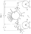
- Fig. 1 is a front view schematically illustrating an example of an inside structure of a printer to which the invention can be applied.
- a printer 1 in a printer 1, one sheet S (web) of which both ends are wound around a feeding shaft 20 and a winding shaft 40 in a roll shape is stretched between the feeding shaft 20 and the winding shaft 40, and the sheet S is transported from the feeding shaft 20 to the winding shaft 40 along a transportation path Pc that stretches in this manner.
- a feed roller R20 and a winding roller R40 are formed such that both ends of the sheet S in the transportation path Pc are wound in a roll shape. Therefore, the sheet S is transported from the feed roller R20 supported by the feeding shaft 20 to the winding roller R40 supported by the winding shaft 40 in a roll-to-roll manner.
- the printer 1 includes a feed unit 2 (a feed area) that feeds the sheet S from the feeding shaft 20, a process unit 3 (a process area) that records an image on the sheet S that is fed by the feed unit 2, and a winding unit 4 (a winding area) that winds the sheet S on which the image is recorded by the process unit 3 around the winding shaft 40.
- a feed unit 2 a feed area
- a process unit 3 a process area
- a winding unit 4 a winding area
- the feed unit 2 has the feeding shaft 20 around which an end of the sheet S is wound, and a driven roller 21 that winds the sheet S pulled out from the feeding shaft 20.
- the feeding shaft 20 supports the sheet S by winding an end of the sheet S in a state in which the front surface of the sheet S faces outside. Further, the feeding shaft 20 rotates in a clockwise direction of Fig. 1 so that the sheet S wound around the feeding shaft 20 is fed through the driven roller 21 to the process unit 3.
- the sheet S is wound around the feeding shaft 20 interposing a core tube 22 detachably provided to the feeding shaft 20. Accordingly, when the sheet S of the feeding shaft 20 is used up, a new core tube 22 around which the sheet S is wound in a roll shape is mounted on the feeding shaft 20 so that the sheet S of the feeding shaft 20 can be replaced.
- a corona processing device 7 is provided between the feeding shaft 20 and the driven roller 21 in the transportation path Pc of the sheet S.
- the corona processing device 7 has a support roller 71 that winds the sheet S reaching the driven roller 21 from the feeding shaft 20 on the back surface and a corona charger 73 that faces the support roller 71, thereby interposing the sheet S.
- the support roller 71 is grounded and functions as an earth electrode.
- the corona charger 73 has a corona discharge electrode 731 and an electrode cover 733 that covers the corona discharge electrode 731.
- the corona discharge electrode 731 is disposed to face the support roller 71 interposing the sheet S, and causes a corona discharge to occur between the corona discharge electrode 731 and the support roller 71 when receiving an application of a voltage.
- a corona process (a front surface modifying process) is performed on the front surface of the sheet S that is wound around the support roller 71 by the corona discharge.
- Fig. 2 is a perspective view schematically illustrating a structure of a steering mechanism that displaces a rotating shaft, a corona processing device, and a driven roller.
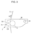
- Fig. 3 is a front view schematically illustrating an example of supporting a corona processing device by the steering mechanism of Fig. 2 . Further, in Fig. 3 , portions hidden by mounting flat plates 86 described below in the front view (the corona processing device 7 and a part of the sheet S) are illustrated by dashed lines.
- a steering mechanism 8 has a movable support member 81 displaceable in an axial direction Da of the feeding shaft 20.
- the movable support member 81 has a movable plate 811 displaceably supported in the axial direction Da inside the printer 1 and a pillar member 812 provided in the upper direction from the movable plate 811 and displaced in the axial direction Da integrally with the movable plate 811.
- the movable support member 81 supports three shafts 83, 84, and 85 that extend in the axial direction Da parallel to one another.
- the shaft 83 is mounted on the movable plate 811 by mounting members 813, and rotatably supports the feeding shaft 20. Further, a feed motor M20 is adjacent to the shaft 83 and mounted on the movable plate 811. Further, the feeding shaft 20 rotates by receiving driving force from the feed motor M20 so that the sheet S is fed from the feeding shaft 20 in a transportation direction Ds intersecting the axial direction Da.
- the shaft 84 is mounted in the center of the pillar member 812 and positioned between the feeding shaft 20 and the driven roller 21 in a vertical direction. Additionally, the corona processing device 7 described above is mounted on the shaft 84. Specifically, two shaft mounting portions 841 are provided on the shaft 84 with a space corresponding to a width of the corona processing device 7 in the axial direction Da, and the mounting flat plates 86 illustrated in Fig. 3 are fixed to each of the shaft mounting portions 841. The corona processing device 7 is interposed between the mounting flat plates 86 and supported by the movable support member 81. Additionally, the sheet S fed from the feeding shaft 20 passes between the corona charger 73 and the support roller 71 supported by the movable support member 81 in the transportation direction Ds and is subjected to a corona process.
- the shaft 85 is mounted at a top end of the pillar member 812 and rotatably supports the driven roller 21. Further, since the shafts 83, 84, and 85 described above are parallel to one another, the driven roller 21 is supported parallel to the feeding shaft 20 and the support roller 71. In addition, the sheet S that is fed from the feeding shaft 20 and passes through the corona processing device 7 is fed through (via) the driven roller 21 to the process unit 3.
- the movable support member 81 of the steering mechanism 8 supports the feeding shaft 20, the corona processing device 7, and the driven roller 21 in an integrated manner. Further, the movable support member 81 is provided displacably in the axial direction Da. Accordingly, the movable support member 81 is driven in the axial direction Da by an axial direction drive motor Ma ( Fig. 4 ) described below so that the feeding shaft 20 can be displaced in the axial direction Da and also the corona processing device 7 and the driven roller 21 can be displaced in the axial direction Da integrally with the feeding shaft 20. Further, a position of the sheet S is adjusted in the axial direction Da by displacing the feeding shaft 20.
- the sheet S of which the position is adjusted by the feed unit 2 is fed to the process unit 3.
- the position of the sheet S is adjusted by performing feedback control on a displacement amount of the feeding shaft 20 based on a result obtained by detecting an end of the sheet in the axial direction Da by an edge sensor Se disposed between the driven roller 21 and a front drive roller 31.
- the process unit 3 supports the sheet S fed from the feed unit 2 by a rotating drum 30 and appropriately performs processes by function units 51, 52, 61, 62, and 63 arranged along a circumference surface of the rotating drum 30 to record an image on the sheet S.
- the front drive roller 31 and a rear drive roller 32 are provided on both sides of the rotating drum 30, and the sheet S transported from the front drive roller 31 to the rear drive roller 32 is supported by the rotating drum 30 to be subjected to image recording.
- the front drive roller 31 has a plurality of fine protrusions formed by thermal spraying on a circumference surface, and supports the sheet S fed from the feed unit 2 on the back surface. Accordingly, the front drive roller 31 rotates in the clockwise direction of Fig. 1 so that the sheet S fed from the feed unit 2 is transported to the downstream side of a transportation path.
- a nip roller 31n is provided against the front drive roller 31. The nip roller 31n is in contact with the front surface of the sheet S in a state of being biased to the front drive roller 31, and interposes the sheet S between the nip roller 31n and the front drive roller 31.
- the rotating drum 30 is a cylindrical drum having a diameter of 400 mm and rotatably supported by a supporting mechanism (not illustrated), and winds the sheet S transported from the front drive roller 31 to the rear drive roller 32 on the back surface.
- the rotating drum 30 is driven to rotate in the transportation direction Ds of the sheet S that receives friction force between the rotating drum 30 and the sheet S, and supports the sheet S on the back surface.
- driven rollers 33 and 34 that fold back the sheet S on the both sides of a portion wound around the rotating drum 30 are provided in the process unit 3.
- the driven roller 33 winds the front surface of the sheet S between the front drive roller 31 and the rotating drum 30 to fold back the sheet S.
- the driven roller 34 winds the front surface of the sheet S between the rotating drum 30 and the rear drive roller 32 to fold back the sheet S.
- the sheet S is folded back against the rotating drum 30 at each of the upstream and downstream sides in the transportation direction Ds so that the portion of the sheet S wound around the rotating drum 30 can be secured to be long.
- the rear drive roller 32 has a plurality of fine protrusions formed by thermal spraying on a circumference surface, and supports the sheet S transported from the rotating drum 30 through the driven roller 34 on the back surface. Further, the rear drive roller 32 transports the sheet S to the winding unit 4 by rotating in the clockwise direction of Fig. 1 .
- a nip roller 32n is provided against the rear drive roller 32. The nip roller 32n is in contact with the front surface of the sheet S in a state of being biased to the rear drive roller 32 and interposes the sheet S between the nip roller 32n and the rear drive roller 32. According to this, friction force between the rear drive roller 32 and the sheet S can be secured, and the sheet S can be reliably transported by the rear drive roller 32.
- the sheet S transported from the front drive roller 31 to the rear drive roller 32 is supported by the circumference surface of the rotating drum 30.
- a plurality of recording heads 51 corresponding to colors different from each other are arranged in the process unit 3 in order to record a color image on the front surface of the sheet S supported by the rotating drum 30.
- four recording heads 51 corresponding to yellow, cyan, magenta, and black are lined up in the transportation direction Ds in this color sequence.
- the recording heads 51 face the front surface of the sheet S wound around the rotating drum 30 with a slight clearance, and eject ink of the corresponding colors (colored ink) from nozzles in an ink jet method.
- the recording heads 51 eject ink to the sheet S transported in the transportation direction Ds so that a color image is formed on the front surface of the sheet S.
- UV (ultraviolet) ink photo curing ink
- UV irradiators 61 and 62 light irradiating units
- the curing of the ink is performed in two steps of preliminary curing and main curing.
- the UV irradiators 61 for the preliminary curing are arranged in spaces between the plurality of recording heads 51.
- the UV irradiators 61 radiate ultraviolet rays in a small integrated amount so that the ink is cured to a degree in which an ink shape is not broken down (preliminary curing), and the ink is not completely cured.
- the UV irradiator 62 for main curing is provided at the downstream side of the plurality of the recording heads 51 in the transportation direction Ds. That is, the UV irradiator 62 radiates an ultraviolet ray in an integrated amount more than the UV irradiators 61 so that the ink is completely cured (main curing).
- the UV irradiators 61 arranged in the spaces between the plurality of recording heads 51 perform preliminary curing on colored ink ejected to the sheet S from the recording heads 51 at the upstream side in the transportation direction Ds. Accordingly, ink ejected by one of the recording heads 51 to the sheet S is subjected to preliminary curing until the ejected ink reaches another recording head 51 adjacent to the one recording head 51 at the downstream side in the transportation direction Ds. According to this, occurrence of color mixture in which colored ink is mixed with different colored ink is suppressed. In a state in which the color mixture is suppressed, the plurality of recording heads 51 eject colored ink with colors different from one another so that a color image is formed on the sheet S.
- the UV irradiator 62 for main curing is provided at the downstream side of the plurality of recording heads 51 in the transportation direction Ds. For this, the color image formed by the plurality of recording heads 51 is subjected to the main curing by the UV irradiator 62 and fixed on the sheet S.
- a recording head 52 is provided at the downstream side of the UV irradiator 62 in the transportation direction Ds.
- the recording head 52 faces the front surface of the sheet S wound around the rotating drum 30 with some clearance, and ejects transparent UV ink from a nozzle to the front surface of the sheet S in the ink jet method. That is, the transparent ink is further ejected to the color image formed by the recording heads 51 for four colors. The transparent ink is ejected to the entire surface of the color image so as to give glossy or matte texture to the color image.
- a UV irradiator 63 is provided at the downstream side of the recording head 52 in the transportation direction Ds. The UV irradiator 63 completely cures the transparent ink ejected by the recording head 52 by radiating a strong ultraviolet ray (main curing). According to this, the transparent ink can be fixed on the front surface of the sheet S.
- ink is appropriately ejected and cured and a color image on which the transparent ink is coated is formed.
- the sheet S on which the color image is printed by the process unit 3 is subjected to a front surface modifying process in advance before being fed to the recording heads 51 and 52. That is, since the color image is formed by ejecting ink to the sheet S subjected to the front surface modifying process, the good quality color image can be formed. Further, the sheet S on which the color image is formed is transported to the winding unit 4 by the rear drive roller 32.
- the winding unit 4 has a driven roller 41 that is provided between the winding shaft 40 and the rear drive roller 32 and winds the sheet S on the back surface.
- the winding shaft 40 supports the sheet S by winding an end of the sheet S in a state in which the front surface of the sheet S faces outside. That is, when the winding shaft 40 rotates in the clockwise direction of Fig. 1 , the sheet S transported from the rear drive roller 32 passes through the driven roller 41 and is wound around the winding shaft 40.
- the sheet S is wound around the winding shaft 40 interposing a core tube 42 detachably attached to the winding shaft 40. Accordingly, when the sheet S wound around the winding shaft 40 is full, the sheet S together with the core tube 42 can be taken out.
- Fig. 4 is a block diagram schematically illustrating an electrical configuration for controlling the printer illustrated in Fig. 1 .
- the operation of the printer 1 described above is controlled by a host computer 10 illustrated in Fig. 4 .
- a host control unit 100 that integrates control operations includes a Central Processing Unit (CPU) and a memory.
- a driver 120 is provided to the host computer 10, and the driver 120 reads a program 124 from a medium 122.
- the host control unit 100 controls each part in the host computer 10 and controls an operation of the printer 1 based on the program 124 read from the medium 122.
- the host computer 10 is provided with a monitor 130 including a liquid crystal display and the like and an operation unit 140 including a keyboard and a mouse, as an interface with an operator.
- a menu screen is displayed on the monitor 130.
- the operator checks the monitor 130 and operates the operation unit 140 to open a printing setting screen from the menu screen and set various types of printing conditions such as a type of recording medium, a size of the recording medium, and printing quality.
- a specific configuration of the interface of the operator can be modified in various manners.
- a touch panel display may be used as the monitor 130, and the operation unit 140 may be configured by the touch panel of the monitor 130.
- the printer 1 is provided with a printer control unit 200 that controls each part in the printer 1 in response to an instruction from the host computer 10. Further, the recording heads, the UV irradiators, and units in an device relating to sheet transportation are controlled by the printer control unit 200. Detailed control of each unit in the device by the printer control unit 200 is described as follows.
- the printer control unit 200 controls an ink ejecting timing of each of the recording heads 51 for forming a color image according to the transportation of the sheet S. Specifically, the control of the ink ejecting timings is performed based on an output (detection value) of a drum encoder E30 that is mounted on a rotating shaft of the rotating drum 30 and detects a rotating position of the rotating drum 30. That is, since the rotating drum 30 is driven to rotate corresponding to the transportation of the sheet S, the transportation position of the sheet S can be found out by referring to the output of the drum encoder E30 that detects the rotating position of the rotating drum 30.
- the printer control unit 200 generates a pts (print timing signal) signal from the output of the drum encoder E30 and controls the ink ejecting timing of each of the recording heads 51 based on the pts signal so that the ink ejected by each of the recording heads 51 is impacted on a target position of the transported sheet S to form a color image.
- a pts print timing signal
- the timing at which the recording head 52 ejects the transparent ink is controlled by the printer control unit 200 based on the output of the drum encoder E30 in the same manner. According to this, the transparent ink can be correctly ejected to the color image formed by the plurality of recording heads 51. Further, on and off timings of the UV irradiators 61, 62, and 63 and the amount of the radiated light are controlled by the printer control unit 200.
- the printer control unit 200 administers a function of controlling the transportation of the sheet S described below with reference to Fig. 1 . That is, a motor is connected to each of the feeding shaft 20, the front drive roller 31, the rear drive roller 32, and the winding shaft 40 among members configuring a sheet transportation system. Further, the printer control unit 200 rotates the motors and also controls speed and torque of each motor to control the transportation of the sheet S. Detailed control of the transportation of the sheet S is as described below.
- the printer control unit 200 rotates the feed motor M20 that drives the feeding shaft 20 to supply the sheet S from the feeding shaft 20 to the front drive roller 31. At this point, the printer control unit 200 controls torque of the feed motor M20 to adjust a tension of the sheet S from the feeding shaft 20 to the front drive roller 31 (a feed tension Ta). That is, a tension sensor S21 that detects the feed tension Ta is mounted on the driven roller 21 disposed between the feeding shaft 20 and the front drive roller 31. For example, the tension sensor S21 can be configured with a load cell that detects force received from the sheet S. Additionally, the printer control unit 200 performs feedback control on the torque of the feed motor M20 based on the detection result of the tension sensor S21 to adjust the feed tension Ta of the sheet S.
- the printer control unit 200 rotates a front drive motor M31 that drives the front drive roller 31 and a rear drive motor M32 that drives the rear drive roller 32. According to this, the sheet S fed from the feed unit 2 passes through the process unit 3. At this point, speed control is performed on the front drive motor M31 and torque control is performed on the rear drive motor M32. That is, the printer control unit 200 adjusts the rotational speed of the front drive motor M31 to be constant based on an encoder output of the front drive motor M31. According to this, the sheet S is transported at constant speed by the front drive roller 31.
- the printer control unit 200 controls torque of the rear drive motor M32 to adjust a tension of the sheet S from the front drive roller 31 to the rear drive roller 32 (a process tension Tb). That is, a tension sensor S34 that detects the process tension Tb is mounted on the driven roller 34 disposed between the rotating drum 30 and the rear drive roller 32.
- the tension sensor S34 can be configured with a load cell that detects force received from the sheet S.
- the printer control unit 200 performs feedback control on the torque of the rear drive motor M32 based on the detection result of the tension sensor S34 to adjust the process tension Tb of the sheet S.
- the printer control unit 200 rotates a winding motor M40 that drives the winding shaft 40 to wind the sheet S transported by the rear drive roller 32 around the winding shaft 40.
- the printer control unit 200 controls torque of the winding motor M40 to adjust a tension of the sheet S from the rear drive roller 32 to the winding shaft 40 (a winding tension Tc).
- a tension sensor S41 that detects the winding tension Tc is mounted on the driven roller 41 disposed between the rear drive roller 32 and the winding shaft 40.
- the tension sensor S41 can be configured with a load cell that detects force received from the sheet S.
- the printer control unit 200 performs feedback control on the torque of the winding motor M40 based on the detection result of the tension sensor S41 to adjust the winding tension Tc of the sheet S.
- the printer control unit 200 also carries out a function of controlling the corona processing device 7. Specifically, the printer control unit 200 adjusts voltage applied to the corona discharge electrode 731 included in the corona charger 73. According to this, wettability of ink to the sheet S can be adapted by adjusting energy provided to a corona process.
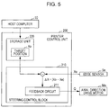
- the printer control unit 200 carries out a function of controlling the steering mechanism 8 described above, and performs feedback control on the axial direction drive motor Ma based on the detection result of the edge sensor Se. Specifically, the printer control unit 200 performs steering control using a steering control block 210 and a storage unit 220 which are embedded as illustrated in Fig. 5 .
- Fig. 5 is a block diagram illustrating an outline of an electrical configuration in which steering control is performed.
- the axial direction drive motor Ma adjusts a position in the axial direction Da of the sheet S by displacing the feeding shaft 20 in the axial direction Da by an amount corresponding to the operation amount Q so that the deviation ⁇ X converges to zero (that is, the detected position Xe approaches to the target position Xo). In this manner, it becomes possible to adjust the position of the sheet S with high accuracy and appropriately control the position of the sheet S fed to the recording heads 51 and 52.
- the support roller 71 that supports the sheet S subjected to the corona process between the feeding shaft 20 and the recording heads 51 and 52 displaces the sheet S according to the displacement of the feeding shaft 20 that feeds the sheet S. Accordingly, if the feeding shaft 20 is displaced, the support roller 71 is also displaced. Therefore, the support roller 71 interrupting the displacement of the sheet S accompanied by the displacement of the feeding shaft 20 can be suppressed. As a result, the position of the sheet S that is fed to the recording heads 51 and 52 can be properly controlled by smoothly displacing the sheet S according to the displacement of the feeding shaft 20 in the axial direction Da.
- the corona charger 73 is displaced according to the displacement of the support roller 71, the advantages are as follows. That is, if the sheet S is displaced according to the displacement of the support roller 71 and the positional relationship between the corona charger 73 and the sheet S is therefore changed, there is a concern that the corona process by the corona charger 73 may be affected. By contrast, if the corona charger 73 is displaced along with the displacement of the support roller 71, the change in the positional relationship between the corona charger 73 and the sheet S is suppressed, so the corona process can be stably performed.
- the nip portion N that nips the sheet S with a pair of the rollers 31 and 31n disposed between the feeding shaft 20 and the recording heads 51 and 52 is provided.
- the position of the sheet S from the nip portion N to the feeding shaft 20 is adjusted according to the displacement of the feeding shaft 20.
- the positional change of the sheet S from the nip portion N to the recording heads 51 and 52 is suppressed by the nip so that the sheet S is stably fed to the recording heads 51 and 52.
- the sheet S of which the position is adjusted until the sheet S reaches the nip portion N can be stably fed from the nip portion N to the recording heads 51 and 52.
- the support roller 71 provided between the feeding shaft 20 and the nip portion N in order to support the sheet S subjected to the corona process is displaced according to the displacement of the feeding shaft 20. Therefore, the position of the sheet S can be appropriately adjusted until the sheet S reaches the nip portion N without being interrupted by the support roller 71 and also the sheet S can be stably fed from the nip portion N to the recording heads 51 and 52. As a result, the position of the sheet S that is fed to the recording heads 51 and 52 can be controlled more appropriately.
- the printer 1 corresponds to an example of "a printing apparatus” of the invention
- the feeding shaft 20 corresponds to an example of a “rotating shaft” of the invention
- the axial direction Da corresponds to an example of an "axial direction” of the invention
- the recording heads 51 and 52 correspond to examples of a "print head” of the invention
- the support roller 71 corresponds to an example of a “support member” of the invention
- the corona processing device 7 corresponds to an example of a “process execution unit” of the invention
- the corona process corresponds to an example of a "front surface modifying process” of the invention
- the steering mechanism 8 corresponds to an example of a "displacement mechanism” of the invention
- the sheet S corresponds to an example of a "recording medium” of the invention
- the movable support member 81 and the axial direction drive motor Ma work in cooperation as an example of a "drive unit” of the invention
- the nip portion N corresponds to an example of a "nip portion
- Fig. 6 is a front view schematically illustrating a modification of a corona processing device.
- portions hidden by the mounting flat plates 86 in the front view are illustrated by dashed lines like in Fig. 3 .
- the corona processing device 7 illustrated in Fig. 6 is different from the corona processing device 7 described above in that driven rollers 711 having small diameters are provided on both sides of the support roller 71, respectively. That is, the driven rollers 711 wind the front surface of the sheet S at both upstream and downstream sides of the support roller 71 in the transportation direction Ds so that the sheet S is folded back. According to the configuration, the portion of the sheet S wound around the support roller 71 can be secured to be long.
- each of the driven rollers 711 is interposed between two mounting flat plates 86 and supported integrally with each of the members 71 and 73 that are included in the corona processing device 7.
- the support roller 71 but also the driven rollers 711 can be displaced in the axial direction Da according to the displacement of the feeding shaft 20 in the axial direction Da. Accordingly, the sheet S can be smoothly displaced according to the displacement of the feeding shaft 20 without being interrupted by the support roller 71 and the driven rollers 711.
- the steering mechanism 8 displaces the support roller 71 according to the displacement of the feeding shaft 20 by integrally driving the feeding shaft 20 and the support roller 71.
- the steering mechanism 8 may be configured so that the support roller 71 is displaced according to the displacement of the feeding shaft 20 by respectively providing motors to the feeding shaft 20 and the support roller 71 and independently driving the feeding shaft 20 and the support roller 71 with the corresponding motors.
- the displacement amounts of the feeding shaft 20 and the support roller 71 may be the same.
- the displacement amounts of the feeding shaft 20 and the support roller 71 can be different.
- the displacement amount of the support roller 71 in the axial direction Da may be smaller or larger than the displacement amount of the feeding shaft 20 in the axial direction Da.
- the front drive roller 31 among the pair of rollers 31 and 31n that configure the nip portion N is a drive roller that receives drive force from the front drive motor M31.
- neither of the pair of rollers 31 and 31n that configures the nip portion N need necessarily be a drive roller and both of the rollers may be driven rollers.
- the nip portion N is not an essential element. Accordingly, the nip portion N need not be provided between the feeding shaft 20 and the recording heads 51 and 52.
- a drive roller may be provided between the feeding shaft 20 and the recording heads 51 and 52 like the front drive roller 31 ( Fig. 1 ) in the embodiment described above.
- the position of the sheet S from the front drive roller 31 to the feeding shaft 20 is adjusted according to the displacement of the feeding shaft 20 and the sheet S is stably fed to the recording heads 51 and 52 by driving the front drive roller 31 from the front drive roller 31 to the recording heads 51 and 52. That is, the sheet S of which the position is adjusted until the sheet S reaches the front drive roller 31 can be stably fed from the front drive roller 31 to the recording heads 51 and 52.
- the support roller 71 provided between the feeding shaft 20 and the front drive roller 31 in order to support the sheet S subjected to the corona process is displaced according to the displacement of the feeding shaft 20. Therefore, the position of the sheet S is appropriately adjusted until the sheet S reaches the front drive roller 31 without being interrupted by the support roller 71, and then the sheet S can be stably fed from the front drive roller 31 to the recording heads 51 and 52. As a result, the position of the sheet S fed to the recording heads 51 and 52 can be controlled more appropriately.
- the corona charger 73 is displaced integrally with the feeding shaft 20.
- the corona charger 73 can be fixed independently of the displacement of the feeding shaft 20.
- the driven roller 21 is provided between the support roller 71 and the front drive roller 31.
- the driven roller 21 need not be provided.
- the support roller 71 is displaced by receiving drive force of the axial direction drive motor Ma.
- the support roller 71 may be configured to be displaced according to the displacement of the feeding shaft 20 by configuring that the support roller 71 is supported by an elastic member such as a spring, and the support roller 71 is displaced by receiving a reaction of the sheet S.
- edge sensor Se Various changes to a disposition position and the number of the edge sensor Se can be made.
- various types of sensors such as an optical sensor or a ultrasonic sensor can be used as a type of edge sensor Se.
- the corona process is performed as a front surface modifying process is described as an example.
- details of the front surface modifying process are not limited to the corona process. Accordingly, it may be configured so that a front surface modifying process such as plasma processing or a front surface treatment of coating a liquid is performed.
Description
- The present invention relates to a printing apparatus and a printing method for printing on a recording medium by a print head by feeding the recording medium to the print head using a rotating shaft that feeds the recording medium by rotating so that a position of the recording medium that is fed to the print head is adjusted by displacing the rotating shaft in an axial direction.
- An apparatus for printing by an ink ejecting head on a recording medium by feeding the recording medium wound in a roll shape from a paper feeding unit to the ink ejecting head is illustrated in
Fig. 6 ofJP-A-2012-200905 JP-A-2012-200905 - However, if a recording medium is fed to a print head (ink ejecting head) using a mechanism such as the paper feeding unit that feeds the recording medium by rotating a rotating shaft that supports the recording medium, printing is not appropriately performed on the recording medium since the recording medium may be fed to the print head in a state where position deviation of the recording medium occurs in an axial direction of the rotating shaft. In contrast, the position of the recording medium from the rotating shaft to the print head is adjusted in the axial direction by displacing the rotating shaft in the axial direction so that the position deviation of the recording medium that is fed to the print head can be suppressed. However, as disclosed in
JP-A-2012-200905 - An advantage of some aspects of the invention is to provide a technique in which a recording medium can be smoothly displaced according to displacement of a rotating shaft in an axial direction and a position of the recording medium that is fed to a print head can be appropriately controlled in a configuration in which a support member that supports the recording medium subjected to a front surface modifying process is provided between the rotating shaft that feeds the recording medium and the print head.
- According to an aspect of the invention, there is provided a printing apparatus which includes a rotating shaft that is displacably provided in an axial direction and feeds a recording medium by rotating, a print head that prints on the recording medium that is fed from the rotating shaft, a support member that supports the recording medium between the rotating shaft and the print head, a process execution unit that performs a front surface modifying process on the recording medium supported by the support member, and a displacement mechanism that displaces the support member according to displacement of the rotating shaft.
- According to another aspect of the invention, there is provided a printing method for printing by a print head on a recording medium that is fed from a rotating shaft to the print head which includes feeding the recording medium by displacing the rotating shaft in an axial direction and rotating the rotating shaft, performing a front surface modifying process on the recording medium supported by a support member between the rotating shaft and the print head, and printing by the print head on the recording medium that is fed to the print head after being subjected to the front surface modifying process, so that the support member is displaced according to displacement of the rotating shaft.
- In the printing apparatus and the printing method configured as above, the support member that supports the recording medium subjected to the front surface modifying process between the rotating shaft and the print head is displaced according to displacement of the rotating shaft that feeds the recording medium. Accordingly, since the support member is also displaced if the rotating shaft is displaced, interruption by the support member of displacement of the recording medium accompanied by the displacement of the rotating shaft can be suppressed. As a result, it is possible to appropriately control a position of the recording medium that is fed to the print head by smoothly displacing the recording medium according to the displacement of the rotating shaft in the axial direction.
- At this point, the printing apparatus may be configured so that the process execution unit is displaced according to the displacement of the support member. That is, if the recording medium is displaced according to the displacement of the support member, a positional relationship between the process execution unit and the recording medium could be changed so the front surface modifying process by the process execution unit is affected. In contrast, if the process execution unit is displaced according to the displacement of the support unit, it is possible to suppress the change in the positional relationship between the process execution unit and the recording medium and stably perform the front surface modifying process.
- Additionally, various aspects can be considered for a specific configuration of a displacement mechanism for displacing a support member according to displacement of a rotating shaft. Accordingly, the displacement mechanism may include a drive unit that displaces the support member according to displacement of a rotating shaft by integrally driving the rotating shaft and the support member. Otherwise, the displacement mechanism may include a drive unit that displaces the support member according to the displacement of the rotating shaft by independently driving the rotating shaft and the support member.
- In addition, the printing apparatus may further include a nip portion that nips the recording medium with a pair of rollers disposed between the rotating shaft and the print head so that the support member supports the recording medium between the rotating shaft and the nip portion. In a configuration in which the recording medium is nipped by the nip portion between the rotating shaft and the print head in this manner, the position of the recording medium from the nip portion to the rotating shaft is adjusted according to the displacement of the rotating shaft, and the change in the position of the recording medium from the nip portion to the print head is suppressed by nipping so that the feeding of the recording medium to the print head can be stably performed. That is, the recording medium of which the position is adjusted until the recording medium reaches the nip portion can be stably fed from the nip portion to the print head. Further, the support member provided between the rotating shaft and the nip portion in order to support the recording medium subjected to the front surface modifying process is displaced according to the displacement of the rotating shaft. Therefore, the position of the recording medium is appropriately adjusted until the recording medium reaches the nip portion without being interrupted by the support member and further the recording medium can be stably fed from the nip portion to the print head. As a result, the position of the recording medium that is fed to the print head can be controlled more appropriately.
- Alternatively, the printing apparatus may further include a drive roller that supports the recording medium between the rotating shaft and the print head and feeds the recording medium to the print head, so that the support member supports the recording medium between the rotating shaft and the drive roller. In a configuration in which the drive roller supports the recording medium between the rotating shaft and the print head and feeds the recording medium to the print head in this manner, the position of the recording medium from the drive roller to the rotating shaft is adjusted according to the displacement of the rotating shaft and the feeding of the recording medium to the print head can be stably performed by driving the drive roller from the drive roller to the print head. That is, the recording medium of which the position is adjusted until the recording medium reaches the drive roller can be stably fed from the drive roller to the print head. Further, the support member provided between the rotating shaft and the drive roller in order to support the recording medium subjected to the front surface modifying process is displaced according to the displacement of the rotating shaft. Therefore, the position of the recording medium is appropriately adjusted until the recording medium reaches the drive roller without being interrupted by the support member, and also the recording medium can be stably fed from the drive roller to the print head. As a result, the position of the recording medium that is fed to the print head can be controlled more appropriately.
- Further, the printing apparatus may further include a detection unit that detects a position of the recording medium in the axial direction so that the displacement amount of the rotating shaft in the axial direction is controlled based on a detection result of the detection unit. According to the configuration, the position of the recording medium can be adjusted with high accuracy so that the position of the recording medium that is fed to the print head can be controlled appropriately.
- Embodiments of the invention will now be described by way of example only with reference to the accompanying drawings, wherein like numbers reference like elements.
-
Fig. 1 is a diagram illustrating a configuration of devices included in a printer to which the invention can be applied. -
Fig. 2 is a diagram illustrating a steering mechanism that displaces a rotating shaft, a corona processing device, and a driven roller. -
Fig. 3 is a diagram illustrating a state of supporting a corona processing device by the steering mechanism ofFig. 2 . -
Fig. 4 is a block diagram schematically illustrating an electrical configuration for controlling the printer illustrated inFig. 1 . -
Fig. 5 is a block diagram illustrating an exemplary outline of an electrical configuration in which steering control is performed. -
Fig. 6 is a front view schematically illustrating a modification of a corona processing device. -
Fig. 1 is a front view schematically illustrating an example of an inside structure of a printer to which the invention can be applied. As illustrated inFig. 1 , in aprinter 1, one sheet S (web) of which both ends are wound around afeeding shaft 20 and a windingshaft 40 in a roll shape is stretched between thefeeding shaft 20 and thewinding shaft 40, and the sheet S is transported from thefeeding shaft 20 to the windingshaft 40 along a transportation path Pc that stretches in this manner. In other words, a feed roller R20 and a winding roller R40 are formed such that both ends of the sheet S in the transportation path Pc are wound in a roll shape. Therefore, the sheet S is transported from the feed roller R20 supported by thefeeding shaft 20 to the winding roller R40 supported by the windingshaft 40 in a roll-to-roll manner. - Further, in the
printer 1, an image is recorded on the sheet S transported along the transportation path Pc. The kind of sheet S is broadly classified into paper and a film. As specific examples, the paper may include pure paper, cast paper, art paper, coated paper, and the like, and the film may include synthetic paper, Polyethylene terephthalate (PET), polypropylene (PP), and the like. Schematically, theprinter 1 includes a feed unit 2 (a feed area) that feeds the sheet S from thefeeding shaft 20, a process unit 3 (a process area) that records an image on the sheet S that is fed by the feed unit 2, and a winding unit 4 (a winding area) that winds the sheet S on which the image is recorded by theprocess unit 3 around thewinding shaft 40. In addition, in the description below, among the surfaces of the sheet S, a surface on which an image is recorded is referred to as a front surface, and the other surface is referred to as a back surface. - The feed unit 2 has the
feeding shaft 20 around which an end of the sheet S is wound, and a drivenroller 21 that winds the sheet S pulled out from thefeeding shaft 20. Thefeeding shaft 20 supports the sheet S by winding an end of the sheet S in a state in which the front surface of the sheet S faces outside. Further, thefeeding shaft 20 rotates in a clockwise direction ofFig. 1 so that the sheet S wound around thefeeding shaft 20 is fed through the drivenroller 21 to theprocess unit 3. In addition, the sheet S is wound around thefeeding shaft 20 interposing acore tube 22 detachably provided to thefeeding shaft 20. Accordingly, when the sheet S of thefeeding shaft 20 is used up, anew core tube 22 around which the sheet S is wound in a roll shape is mounted on thefeeding shaft 20 so that the sheet S of thefeeding shaft 20 can be replaced. - Further, in the feed unit 2, a
corona processing device 7 is provided between thefeeding shaft 20 and the drivenroller 21 in the transportation path Pc of the sheet S. Thecorona processing device 7 has asupport roller 71 that winds the sheet S reaching the drivenroller 21 from thefeeding shaft 20 on the back surface and acorona charger 73 that faces thesupport roller 71, thereby interposing the sheet S. Thesupport roller 71 is grounded and functions as an earth electrode. Meanwhile, thecorona charger 73 has acorona discharge electrode 731 and anelectrode cover 733 that covers thecorona discharge electrode 731. Thecorona discharge electrode 731 is disposed to face thesupport roller 71 interposing the sheet S, and causes a corona discharge to occur between thecorona discharge electrode 731 and thesupport roller 71 when receiving an application of a voltage. A corona process (a front surface modifying process) is performed on the front surface of the sheet S that is wound around thesupport roller 71 by the corona discharge. - The feeding
shaft 20, thecorona processing device 7, and the drivenroller 21 provided in the feed unit 2 are integrally displaceable in an axial direction of the feeding shaft 20 (in other words, in a width direction of the sheet S that intersects a transportation direction of the sheet S).Fig. 2 is a perspective view schematically illustrating a structure of a steering mechanism that displaces a rotating shaft, a corona processing device, and a driven roller.Fig. 3 is a front view schematically illustrating an example of supporting a corona processing device by the steering mechanism ofFig. 2 . Further, inFig. 3 , portions hidden by mountingflat plates 86 described below in the front view (thecorona processing device 7 and a part of the sheet S) are illustrated by dashed lines. - As illustrated in
Fig. 2 , asteering mechanism 8 has amovable support member 81 displaceable in an axial direction Da of the feedingshaft 20. Themovable support member 81 has amovable plate 811 displaceably supported in the axial direction Da inside theprinter 1 and apillar member 812 provided in the upper direction from themovable plate 811 and displaced in the axial direction Da integrally with themovable plate 811. Themovable support member 81 supports threeshafts - The
shaft 83 is mounted on themovable plate 811 by mountingmembers 813, and rotatably supports the feedingshaft 20. Further, a feed motor M20 is adjacent to theshaft 83 and mounted on themovable plate 811. Further, the feedingshaft 20 rotates by receiving driving force from the feed motor M20 so that the sheet S is fed from the feedingshaft 20 in a transportation direction Ds intersecting the axial direction Da. - The
shaft 84 is mounted in the center of thepillar member 812 and positioned between the feedingshaft 20 and the drivenroller 21 in a vertical direction. Additionally, thecorona processing device 7 described above is mounted on theshaft 84. Specifically, twoshaft mounting portions 841 are provided on theshaft 84 with a space corresponding to a width of thecorona processing device 7 in the axial direction Da, and the mountingflat plates 86 illustrated inFig. 3 are fixed to each of theshaft mounting portions 841. Thecorona processing device 7 is interposed between the mountingflat plates 86 and supported by themovable support member 81. Additionally, the sheet S fed from the feedingshaft 20 passes between thecorona charger 73 and thesupport roller 71 supported by themovable support member 81 in the transportation direction Ds and is subjected to a corona process. - The
shaft 85 is mounted at a top end of thepillar member 812 and rotatably supports the drivenroller 21. Further, since theshafts roller 21 is supported parallel to the feedingshaft 20 and thesupport roller 71. In addition, the sheet S that is fed from the feedingshaft 20 and passes through thecorona processing device 7 is fed through (via) the drivenroller 21 to theprocess unit 3. - In this manner, the
movable support member 81 of thesteering mechanism 8 supports the feedingshaft 20, thecorona processing device 7, and the drivenroller 21 in an integrated manner. Further, themovable support member 81 is provided displacably in the axial direction Da. Accordingly, themovable support member 81 is driven in the axial direction Da by an axial direction drive motor Ma (Fig. 4 ) described below so that the feedingshaft 20 can be displaced in the axial direction Da and also thecorona processing device 7 and the drivenroller 21 can be displaced in the axial direction Da integrally with the feedingshaft 20. Further, a position of the sheet S is adjusted in the axial direction Da by displacing the feedingshaft 20. Accordingly, the sheet S of which the position is adjusted by the feed unit 2 is fed to theprocess unit 3. In addition, as described below, the position of the sheet S is adjusted by performing feedback control on a displacement amount of the feedingshaft 20 based on a result obtained by detecting an end of the sheet in the axial direction Da by an edge sensor Se disposed between the drivenroller 21 and afront drive roller 31. - The
process unit 3 supports the sheet S fed from the feed unit 2 by arotating drum 30 and appropriately performs processes byfunction units rotating drum 30 to record an image on the sheet S. In theprocess unit 3, thefront drive roller 31 and arear drive roller 32 are provided on both sides of therotating drum 30, and the sheet S transported from thefront drive roller 31 to therear drive roller 32 is supported by therotating drum 30 to be subjected to image recording. - The
front drive roller 31 has a plurality of fine protrusions formed by thermal spraying on a circumference surface, and supports the sheet S fed from the feed unit 2 on the back surface. Accordingly, thefront drive roller 31 rotates in the clockwise direction ofFig. 1 so that the sheet S fed from the feed unit 2 is transported to the downstream side of a transportation path. In addition, anip roller 31n is provided against thefront drive roller 31. Thenip roller 31n is in contact with the front surface of the sheet S in a state of being biased to thefront drive roller 31, and interposes the sheet S between thenip roller 31n and thefront drive roller 31. According to this, friction force between thefront drive roller 31 and the sheet S is secured and the sheet S can be definitely transported by thefront drive roller 31. In this manner, a nip portion N that nips the sheet S is formed with a pair of therollers - For example, the
rotating drum 30 is a cylindrical drum having a diameter of 400 mm and rotatably supported by a supporting mechanism (not illustrated), and winds the sheet S transported from thefront drive roller 31 to therear drive roller 32 on the back surface. Therotating drum 30 is driven to rotate in the transportation direction Ds of the sheet S that receives friction force between therotating drum 30 and the sheet S, and supports the sheet S on the back surface. Additionally, drivenrollers rotating drum 30 are provided in theprocess unit 3. Among these, the drivenroller 33 winds the front surface of the sheet S between thefront drive roller 31 and therotating drum 30 to fold back the sheet S. Meanwhile, the drivenroller 34 winds the front surface of the sheet S between therotating drum 30 and therear drive roller 32 to fold back the sheet S. In this manner, the sheet S is folded back against therotating drum 30 at each of the upstream and downstream sides in the transportation direction Ds so that the portion of the sheet S wound around therotating drum 30 can be secured to be long. - The
rear drive roller 32 has a plurality of fine protrusions formed by thermal spraying on a circumference surface, and supports the sheet S transported from therotating drum 30 through the drivenroller 34 on the back surface. Further, therear drive roller 32 transports the sheet S to the windingunit 4 by rotating in the clockwise direction ofFig. 1 . In addition, anip roller 32n is provided against therear drive roller 32. Thenip roller 32n is in contact with the front surface of the sheet S in a state of being biased to therear drive roller 32 and interposes the sheet S between thenip roller 32n and therear drive roller 32. According to this, friction force between therear drive roller 32 and the sheet S can be secured, and the sheet S can be reliably transported by therear drive roller 32. - In this manner, the sheet S transported from the
front drive roller 31 to therear drive roller 32 is supported by the circumference surface of therotating drum 30. Further, a plurality of recording heads 51 corresponding to colors different from each other are arranged in theprocess unit 3 in order to record a color image on the front surface of the sheet S supported by therotating drum 30. Specifically, four recording heads 51 corresponding to yellow, cyan, magenta, and black are lined up in the transportation direction Ds in this color sequence. The recording heads 51 face the front surface of the sheet S wound around therotating drum 30 with a slight clearance, and eject ink of the corresponding colors (colored ink) from nozzles in an ink jet method. In addition, the recording heads 51 eject ink to the sheet S transported in the transportation direction Ds so that a color image is formed on the front surface of the sheet S. - Further, UV (ultraviolet) ink (photo curing ink) that is cured by radiating an ultraviolet ray (light) is used as the ink. Thus,
UV irradiators 61 and 62 (light irradiating units) are provided in theprocess unit 3 in order to cure the ink and fix the ink to the sheet S. In addition, the curing of the ink is performed in two steps of preliminary curing and main curing. The UV irradiators 61 for the preliminary curing are arranged in spaces between the plurality of recording heads 51. That is, theUV irradiators 61 radiate ultraviolet rays in a small integrated amount so that the ink is cured to a degree in which an ink shape is not broken down (preliminary curing), and the ink is not completely cured. Meanwhile, theUV irradiator 62 for main curing is provided at the downstream side of the plurality of the recording heads 51 in the transportation direction Ds. That is, theUV irradiator 62 radiates an ultraviolet ray in an integrated amount more than theUV irradiators 61 so that the ink is completely cured (main curing). - In this manner, the
UV irradiators 61 arranged in the spaces between the plurality of recording heads 51 perform preliminary curing on colored ink ejected to the sheet S from the recording heads 51 at the upstream side in the transportation direction Ds. Accordingly, ink ejected by one of the recording heads 51 to the sheet S is subjected to preliminary curing until the ejected ink reaches anotherrecording head 51 adjacent to the onerecording head 51 at the downstream side in the transportation direction Ds. According to this, occurrence of color mixture in which colored ink is mixed with different colored ink is suppressed. In a state in which the color mixture is suppressed, the plurality of recording heads 51 eject colored ink with colors different from one another so that a color image is formed on the sheet S. Further, theUV irradiator 62 for main curing is provided at the downstream side of the plurality of recording heads 51 in the transportation direction Ds. For this, the color image formed by the plurality of recording heads 51 is subjected to the main curing by theUV irradiator 62 and fixed on the sheet S. - Further, a
recording head 52 is provided at the downstream side of theUV irradiator 62 in the transportation direction Ds. Therecording head 52 faces the front surface of the sheet S wound around therotating drum 30 with some clearance, and ejects transparent UV ink from a nozzle to the front surface of the sheet S in the ink jet method. That is, the transparent ink is further ejected to the color image formed by the recording heads 51 for four colors. The transparent ink is ejected to the entire surface of the color image so as to give glossy or matte texture to the color image. Further, aUV irradiator 63 is provided at the downstream side of therecording head 52 in the transportation direction Ds. TheUV irradiator 63 completely cures the transparent ink ejected by therecording head 52 by radiating a strong ultraviolet ray (main curing). According to this, the transparent ink can be fixed on the front surface of the sheet S. - In this manner, in the
process unit 3, with respect to the sheet S wound around the circumference portion of therotating drum 30, ink is appropriately ejected and cured and a color image on which the transparent ink is coated is formed. The sheet S on which the color image is printed by theprocess unit 3 is subjected to a front surface modifying process in advance before being fed to the recording heads 51 and 52. That is, since the color image is formed by ejecting ink to the sheet S subjected to the front surface modifying process, the good quality color image can be formed. Further, the sheet S on which the color image is formed is transported to the windingunit 4 by therear drive roller 32. - In addition to the winding
shaft 40 that winds an end of the sheet S, the windingunit 4 has a drivenroller 41 that is provided between the windingshaft 40 and therear drive roller 32 and winds the sheet S on the back surface. The windingshaft 40 supports the sheet S by winding an end of the sheet S in a state in which the front surface of the sheet S faces outside. That is, when the windingshaft 40 rotates in the clockwise direction ofFig. 1 , the sheet S transported from therear drive roller 32 passes through the drivenroller 41 and is wound around the windingshaft 40. In addition, the sheet S is wound around the windingshaft 40 interposing acore tube 42 detachably attached to the windingshaft 40. Accordingly, when the sheet S wound around the windingshaft 40 is full, the sheet S together with thecore tube 42 can be taken out. - The configuration of the devices included in the
printer 1 has been outlined as described above. Subsequently, an electrical configuration for controlling theprinter 1 is described as follows.Fig. 4 is a block diagram schematically illustrating an electrical configuration for controlling the printer illustrated inFig. 1 . The operation of theprinter 1 described above is controlled by ahost computer 10 illustrated inFig. 4 . In thehost computer 10, ahost control unit 100 that integrates control operations includes a Central Processing Unit (CPU) and a memory. In addition, adriver 120 is provided to thehost computer 10, and thedriver 120 reads aprogram 124 from a medium 122. In addition, various mediums such as a Compact Disc (CD), a Digital Versatile Disc (DVD), and a Universal Serial Bus (USB) memory can be used as the medium 122. Further, thehost control unit 100 controls each part in thehost computer 10 and controls an operation of theprinter 1 based on theprogram 124 read from the medium 122. - Further, the
host computer 10 is provided with amonitor 130 including a liquid crystal display and the like and anoperation unit 140 including a keyboard and a mouse, as an interface with an operator. In addition to an image of a printing target, a menu screen is displayed on themonitor 130. Accordingly, the operator checks themonitor 130 and operates theoperation unit 140 to open a printing setting screen from the menu screen and set various types of printing conditions such as a type of recording medium, a size of the recording medium, and printing quality. Further, a specific configuration of the interface of the operator can be modified in various manners. For example, a touch panel display may be used as themonitor 130, and theoperation unit 140 may be configured by the touch panel of themonitor 130. - Meanwhile, the
printer 1 is provided with aprinter control unit 200 that controls each part in theprinter 1 in response to an instruction from thehost computer 10. Further, the recording heads, the UV irradiators, and units in an device relating to sheet transportation are controlled by theprinter control unit 200. Detailed control of each unit in the device by theprinter control unit 200 is described as follows. - The
printer control unit 200 controls an ink ejecting timing of each of the recording heads 51 for forming a color image according to the transportation of the sheet S. Specifically, the control of the ink ejecting timings is performed based on an output (detection value) of a drum encoder E30 that is mounted on a rotating shaft of therotating drum 30 and detects a rotating position of therotating drum 30. That is, since therotating drum 30 is driven to rotate corresponding to the transportation of the sheet S, the transportation position of the sheet S can be found out by referring to the output of the drum encoder E30 that detects the rotating position of therotating drum 30. Then, theprinter control unit 200 generates a pts (print timing signal) signal from the output of the drum encoder E30 and controls the ink ejecting timing of each of the recording heads 51 based on the pts signal so that the ink ejected by each of the recording heads 51 is impacted on a target position of the transported sheet S to form a color image. - In addition, the timing at which the
recording head 52 ejects the transparent ink is controlled by theprinter control unit 200 based on the output of the drum encoder E30 in the same manner. According to this, the transparent ink can be correctly ejected to the color image formed by the plurality of recording heads 51. Further, on and off timings of theUV irradiators printer control unit 200. - In addition, the
printer control unit 200 administers a function of controlling the transportation of the sheet S described below with reference toFig. 1 . That is, a motor is connected to each of the feedingshaft 20, thefront drive roller 31, therear drive roller 32, and the windingshaft 40 among members configuring a sheet transportation system. Further, theprinter control unit 200 rotates the motors and also controls speed and torque of each motor to control the transportation of the sheet S. Detailed control of the transportation of the sheet S is as described below. - The
printer control unit 200 rotates the feed motor M20 that drives the feedingshaft 20 to supply the sheet S from the feedingshaft 20 to thefront drive roller 31. At this point, theprinter control unit 200 controls torque of the feed motor M20 to adjust a tension of the sheet S from the feedingshaft 20 to the front drive roller 31 (a feed tension Ta). That is, a tension sensor S21 that detects the feed tension Ta is mounted on the drivenroller 21 disposed between the feedingshaft 20 and thefront drive roller 31. For example, the tension sensor S21 can be configured with a load cell that detects force received from the sheet S. Additionally, theprinter control unit 200 performs feedback control on the torque of the feed motor M20 based on the detection result of the tension sensor S21 to adjust the feed tension Ta of the sheet S. - In addition, the
printer control unit 200 rotates a front drive motor M31 that drives thefront drive roller 31 and a rear drive motor M32 that drives therear drive roller 32. According to this, the sheet S fed from the feed unit 2 passes through theprocess unit 3. At this point, speed control is performed on the front drive motor M31 and torque control is performed on the rear drive motor M32. That is, theprinter control unit 200 adjusts the rotational speed of the front drive motor M31 to be constant based on an encoder output of the front drive motor M31. According to this, the sheet S is transported at constant speed by thefront drive roller 31. - Meanwhile, the
printer control unit 200 controls torque of the rear drive motor M32 to adjust a tension of the sheet S from thefront drive roller 31 to the rear drive roller 32 (a process tension Tb). That is, a tension sensor S34 that detects the process tension Tb is mounted on the drivenroller 34 disposed between therotating drum 30 and therear drive roller 32. For example, the tension sensor S34 can be configured with a load cell that detects force received from the sheet S. In addition, theprinter control unit 200 performs feedback control on the torque of the rear drive motor M32 based on the detection result of the tension sensor S34 to adjust the process tension Tb of the sheet S. - Further, the
printer control unit 200 rotates a winding motor M40 that drives the windingshaft 40 to wind the sheet S transported by therear drive roller 32 around the windingshaft 40. At this point, theprinter control unit 200 controls torque of the winding motor M40 to adjust a tension of the sheet S from therear drive roller 32 to the winding shaft 40 (a winding tension Tc). That is, a tension sensor S41 that detects the winding tension Tc is mounted on the drivenroller 41 disposed between therear drive roller 32 and the windingshaft 40. For example, the tension sensor S41 can be configured with a load cell that detects force received from the sheet S. Further, theprinter control unit 200 performs feedback control on the torque of the winding motor M40 based on the detection result of the tension sensor S41 to adjust the winding tension Tc of the sheet S. - The
printer control unit 200 also carries out a function of controlling thecorona processing device 7. Specifically, theprinter control unit 200 adjusts voltage applied to thecorona discharge electrode 731 included in thecorona charger 73. According to this, wettability of ink to the sheet S can be adapted by adjusting energy provided to a corona process. - Further, the
printer control unit 200 carries out a function of controlling thesteering mechanism 8 described above, and performs feedback control on the axial direction drive motor Ma based on the detection result of the edge sensor Se. Specifically, theprinter control unit 200 performs steering control using asteering control block 210 and astorage unit 220 which are embedded as illustrated inFig. 5 . -
Fig. 5 is a block diagram illustrating an outline of an electrical configuration in which steering control is performed. Thesteering control block 210 provided in theprinter control unit 200 calculates a deviation AX (=Xo-Xe) between a position Xe (that is, a detection result) of an end of the sheet S detected by the edge sensor Se in the axial direction Da and a target position Xo stored in thestorage unit 220 to input the deviation AX to an embeddedfeedback circuit 211. Further, thefeedback circuit 211 provides an operation amount Q. (=KxAX) obtained by multiplying the deviation ΔX by a feedback gain K with the axial direction drive motor Ma. According to this, the axial direction drive motor Ma adjusts a position in the axial direction Da of the sheet S by displacing the feedingshaft 20 in the axial direction Da by an amount corresponding to the operation amount Q so that the deviation ΔX converges to zero (that is, the detected position Xe approaches to the target position Xo). In this manner, it becomes possible to adjust the position of the sheet S with high accuracy and appropriately control the position of the sheet S fed to the recording heads 51 and 52. - As described above, according to the embodiment configured in this manner, the
support roller 71 that supports the sheet S subjected to the corona process between the feedingshaft 20 and the recording heads 51 and 52 displaces the sheet S according to the displacement of the feedingshaft 20 that feeds the sheet S. Accordingly, if the feedingshaft 20 is displaced, thesupport roller 71 is also displaced. Therefore, thesupport roller 71 interrupting the displacement of the sheet S accompanied by the displacement of the feedingshaft 20 can be suppressed. As a result, the position of the sheet S that is fed to the recording heads 51 and 52 can be properly controlled by smoothly displacing the sheet S according to the displacement of the feedingshaft 20 in the axial direction Da. - Further, according to the present embodiment, since the
corona charger 73 is displaced according to the displacement of thesupport roller 71, the advantages are as follows. That is, if the sheet S is displaced according to the displacement of thesupport roller 71 and the positional relationship between thecorona charger 73 and the sheet S is therefore changed, there is a concern that the corona process by thecorona charger 73 may be affected. By contrast, if thecorona charger 73 is displaced along with the displacement of thesupport roller 71, the change in the positional relationship between thecorona charger 73 and the sheet S is suppressed, so the corona process can be stably performed. - In addition, according to the present embodiment, the nip portion N that nips the sheet S with a pair of the
rollers shaft 20 and the recording heads 51 and 52 is provided. In this manner, in the configuration in which the sheet S is nipped by the nip portion N disposed between the feedingshaft 20 and the recording heads 51 and 52, the position of the sheet S from the nip portion N to the feedingshaft 20 is adjusted according to the displacement of the feedingshaft 20. Also the positional change of the sheet S from the nip portion N to the recording heads 51 and 52 is suppressed by the nip so that the sheet S is stably fed to the recording heads 51 and 52. That is, the sheet S of which the position is adjusted until the sheet S reaches the nip portion N can be stably fed from the nip portion N to the recording heads 51 and 52. Further, thesupport roller 71 provided between the feedingshaft 20 and the nip portion N in order to support the sheet S subjected to the corona process is displaced according to the displacement of the feedingshaft 20. Therefore, the position of the sheet S can be appropriately adjusted until the sheet S reaches the nip portion N without being interrupted by thesupport roller 71 and also the sheet S can be stably fed from the nip portion N to the recording heads 51 and 52. As a result, the position of the sheet S that is fed to the recording heads 51 and 52 can be controlled more appropriately. - In this manner, in the embodiment described above, the
printer 1 corresponds to an example of "a printing apparatus" of the invention, the feedingshaft 20 corresponds to an example of a "rotating shaft" of the invention, the axial direction Da corresponds to an example of an "axial direction" of the invention, the recording heads 51 and 52 correspond to examples of a "print head" of the invention, thesupport roller 71 corresponds to an example of a "support member" of the invention, thecorona processing device 7 corresponds to an example of a "process execution unit" of the invention, the corona process corresponds to an example of a "front surface modifying process" of the invention, thesteering mechanism 8 corresponds to an example of a "displacement mechanism" of the invention, the sheet S corresponds to an example of a "recording medium" of the invention, themovable support member 81 and the axial direction drive motor Ma work in cooperation as an example of a "drive unit" of the invention, the nip portion N corresponds to an example of a "nip portion" of the invention, and the edge sensor Se corresponds to an example of a "detection unit" of the invention. - In addition, the invention is not limited to the embodiments as described above, but various modifications can be added to the item described above as long as they do not depart from the scope of the invention as defined by the appended claims. For example, the configuration of the
corona processing device 7 may be modified as illustrated inFig. 6. Fig. 6 is a front view schematically illustrating a modification of a corona processing device. InFig. 6 , portions hidden by the mountingflat plates 86 in the front view (thecorona processing device 7 and a part of the sheet S) are illustrated by dashed lines like inFig. 3 . - The
corona processing device 7 illustrated inFig. 6 is different from thecorona processing device 7 described above in that drivenrollers 711 having small diameters are provided on both sides of thesupport roller 71, respectively. That is, the drivenrollers 711 wind the front surface of the sheet S at both upstream and downstream sides of thesupport roller 71 in the transportation direction Ds so that the sheet S is folded back. According to the configuration, the portion of the sheet S wound around thesupport roller 71 can be secured to be long. In addition, each of the drivenrollers 711 is interposed between two mountingflat plates 86 and supported integrally with each of themembers corona processing device 7. Accordingly, not only thesupport roller 71 but also the drivenrollers 711 can be displaced in the axial direction Da according to the displacement of the feedingshaft 20 in the axial direction Da. Accordingly, the sheet S can be smoothly displaced according to the displacement of the feedingshaft 20 without being interrupted by thesupport roller 71 and the drivenrollers 711. - Further, in the embodiment described above, the
steering mechanism 8 displaces thesupport roller 71 according to the displacement of the feedingshaft 20 by integrally driving the feedingshaft 20 and thesupport roller 71. However, for example, thesteering mechanism 8 may be configured so that thesupport roller 71 is displaced according to the displacement of the feedingshaft 20 by respectively providing motors to the feedingshaft 20 and thesupport roller 71 and independently driving the feedingshaft 20 and thesupport roller 71 with the corresponding motors. At this point, the displacement amounts of the feedingshaft 20 and thesupport roller 71 may be the same. Alternatively, if the feedingshaft 20 and thesupport roller 71 are displaced to the same side in the axial direction Da, the displacement amounts of the feedingshaft 20 and thesupport roller 71 can be different. Specifically, the displacement amount of thesupport roller 71 in the axial direction Da may be smaller or larger than the displacement amount of the feedingshaft 20 in the axial direction Da. - In addition, in the embodiment described above, the
front drive roller 31 among the pair ofrollers rollers - In other words, the nip portion N is not an essential element. Accordingly, the nip portion N need not be provided between the feeding
shaft 20 and the recording heads 51 and 52. In addition, in a configuration in which the nip portion N is not provided, a drive roller may be provided between the feedingshaft 20 and the recording heads 51 and 52 like the front drive roller 31 (Fig. 1 ) in the embodiment described above. - That is, in a configuration in which the
front drive roller 31 winds the sheet S between the feedingshaft 20 and the recording heads 51 and 52 to feed the sheet S to the recording heads 51 and 52, the position of the sheet S from thefront drive roller 31 to the feedingshaft 20 is adjusted according to the displacement of the feedingshaft 20 and the sheet S is stably fed to the recording heads 51 and 52 by driving thefront drive roller 31 from thefront drive roller 31 to the recording heads 51 and 52. That is, the sheet S of which the position is adjusted until the sheet S reaches thefront drive roller 31 can be stably fed from thefront drive roller 31 to the recording heads 51 and 52. Further, thesupport roller 71 provided between the feedingshaft 20 and thefront drive roller 31 in order to support the sheet S subjected to the corona process is displaced according to the displacement of the feedingshaft 20. Therefore, the position of the sheet S is appropriately adjusted until the sheet S reaches thefront drive roller 31 without being interrupted by thesupport roller 71, and then the sheet S can be stably fed from thefront drive roller 31 to the recording heads 51 and 52. As a result, the position of the sheet S fed to the recording heads 51 and 52 can be controlled more appropriately. - In addition, according to the embodiment described above, the
corona charger 73 is displaced integrally with the feedingshaft 20. However, thecorona charger 73 can be fixed independently of the displacement of the feedingshaft 20. - Further, according to the embodiment described above, the driven
roller 21 is provided between thesupport roller 71 and thefront drive roller 31. However, the drivenroller 21 need not be provided. - In addition, according to the embodiment described above, the
support roller 71 is displaced by receiving drive force of the axial direction drive motor Ma. However, thesupport roller 71 may be configured to be displaced according to the displacement of the feedingshaft 20 by configuring that thesupport roller 71 is supported by an elastic member such as a spring, and thesupport roller 71 is displaced by receiving a reaction of the sheet S. - Various changes to a disposition position and the number of the edge sensor Se can be made. In addition, various types of sensors such as an optical sensor or a ultrasonic sensor can be used as a type of edge sensor Se.
- In addition, according to the embodiment described above, a case in which the corona process is performed as a front surface modifying process is described as an example. However, details of the front surface modifying process are not limited to the corona process. Accordingly, it may be configured so that a front surface modifying process such as plasma processing or a front surface treatment of coating a liquid is performed.
- The foregoing description has been given by way of example only and it will be appreciated by a person skilled in the art that modifications can be made without departing from the scope of the present invention.
Claims (8)
- A printing apparatus (1) comprising:a rotating shaft (20) that is displaceable in an axial direction (Da) and is adapted to feed a recording medium (S) by rotating;a print head (51, 52) for printing on the recording medium that is fed from the rotating shaft;a support member (71) for supporting the recording medium between the rotating shaft and the print head;a process execution unit (7) for performing a front surface modifying process on the recording medium supported by the support member (71); anda displacement mechanism (8) for displacing the support member (71) according to displacement of the rotating shaft (20).
- The printing apparatus according to claim 1, wherein the process execution unit is adapted to displace according to displacement of the support member.
- The printing apparatus according to claim 1 or claim 2, wherein the displacement mechanism includes a drive unit (81, Ma) for displacing the support member according to the displacement of the rotating shaft by integrally driving the rotating shaft and the support member.
- The printing apparatus according to claim 1 or claim 2, wherein the displacement mechanism includes a drive unit that displaces the support member according to the displacement of the rotating shaft by independently driving the rotating shaft and the support member.
- The printing apparatus according to any one of the preceding claims, further comprising:a nip portion (N) for nipping the recording medium with a pair of rollers (31, 31a) disposed between the rotating shaft (20) and the print head (51, 52),wherein the support member (71) is adapted to support the recording medium between the rotating shaft (20) and the nip portion (N).
- The printing apparatus according to any one of the preceding claims, further comprising:a drive roller (31) for supporting the recording medium between the rotating shaft (20) and the print head (51, 52) and feeding the recording medium to the print head,wherein the support member is adapted to support the recording medium between the rotating shaft (20) and the drive roller (31).
- The printing apparatus according to any one of the preceding claims, further comprising:a detection unit (Se) for detecting a position of the recording medium in the axial direction,wherein a displacement amount of the rotating shaft in the axial direction is adapted to be controlled based on a detection result of the detection unit.
- A printing method for printing by a print head (51, 52) on a recording medium (S) that is fed from a rotating shaft (20) to the print head, the method comprising:feeding the recording medium by displacing the rotating shaft (20) in an axial direction and rotating the rotating shaft (20);performing a front surface modifying process on the recording medium supported by a support member (71) between the rotating shaft and the print head; andprinting by the print head on the recording medium that is fed to the print head after being subjected to the front surface modifying process,wherein the support member (71) is displaced according to displacement of the rotating shaft (20).
Applications Claiming Priority (1)
| Application Number | Priority Date | Filing Date | Title |
|---|---|---|---|
| JP2013061561A JP6107284B2 (en) | 2013-03-25 | 2013-03-25 | Printing apparatus and printing method |
Publications (2)
| Publication Number | Publication Date |
|---|---|
| EP2783872A1 EP2783872A1 (en) | 2014-10-01 |
| EP2783872B1 true EP2783872B1 (en) | 2016-04-27 |
Family
ID=50336135
Family Applications (1)
| Application Number | Title | Priority Date | Filing Date |
|---|---|---|---|
| EP14160676.4A Active EP2783872B1 (en) | 2013-03-25 | 2014-03-19 | Printing apparatus and printing method |
Country Status (4)
| Country | Link |
|---|---|
| US (2) | US8985732B2 (en) |
| EP (1) | EP2783872B1 (en) |
| JP (1) | JP6107284B2 (en) |
| CN (1) | CN104070849B (en) |
Families Citing this family (6)
| Publication number | Priority date | Publication date | Assignee | Title |
|---|---|---|---|---|
| JP6107284B2 (en) * | 2013-03-25 | 2017-04-05 | セイコーエプソン株式会社 | Printing apparatus and printing method |
| JP2015066739A (en) * | 2013-09-27 | 2015-04-13 | 株式会社Screenホールディングス | Image recorder and base material supply device |
| JP6651943B2 (en) * | 2016-03-30 | 2020-02-19 | セイコーエプソン株式会社 | PRINTING APPARATUS AND CONTROL METHOD OF PRINTING APPARATUS |
| JP6862676B2 (en) | 2016-04-25 | 2021-04-21 | セイコーエプソン株式会社 | Printing device, printing method |
| JP7073928B2 (en) * | 2017-06-14 | 2022-05-24 | 株式会社リコー | Conveyor device, liquid discharge device, reading device, image forming device, control method of the transfer device |
| JP2022002881A (en) | 2020-06-23 | 2022-01-11 | セイコーエプソン株式会社 | Recording apparatus and recording method |
Family Cites Families (14)
| Publication number | Priority date | Publication date | Assignee | Title |
|---|---|---|---|---|
| JPS63112180A (en) * | 1986-10-31 | 1988-05-17 | Olympus Optical Co Ltd | Skew corrector |
| JPH0346953A (en) | 1989-07-14 | 1991-02-28 | Photo Composing Mach Mfg Co Ltd | Sensitized material transfer device with meandering correcting function |
| JP2005349777A (en) * | 2004-06-14 | 2005-12-22 | Star Micronics Co Ltd | Paper feeder of printer |
| JP4273126B2 (en) * | 2005-03-04 | 2009-06-03 | キヤノン株式会社 | Recording apparatus and correction method |
| JP4715894B2 (en) * | 2008-09-25 | 2011-07-06 | 富士ゼロックス株式会社 | Recording device |
| JP2010265062A (en) * | 2009-05-13 | 2010-11-25 | Sharp Corp | Sheet conveyance device and sheet meandering correction method |
| JP5293498B2 (en) * | 2009-08-21 | 2013-09-18 | トヨタ自動車株式会社 | Web conveying apparatus and method and battery manufacturing method |
| JP5495728B2 (en) * | 2009-11-20 | 2014-05-21 | キヤノン株式会社 | Recording device |
| JP5728876B2 (en) * | 2010-10-08 | 2015-06-03 | セイコーエプソン株式会社 | Printing device |
| CN201989423U (en) * | 2010-12-24 | 2011-09-28 | 山东新北洋信息技术股份有限公司 | Paper roll supporting mechanism and printing device using same |
| CN201961870U (en) * | 2011-01-27 | 2011-09-07 | 李玉龙 | Roll paper non-stop unwinding device |
| JP2012200905A (en) | 2011-03-23 | 2012-10-22 | Ricoh Co Ltd | Image forming method and image forming device |
| JP6083179B2 (en) * | 2012-10-01 | 2017-02-22 | 株式会社リコー | Image forming apparatus |
| JP6107284B2 (en) * | 2013-03-25 | 2017-04-05 | セイコーエプソン株式会社 | Printing apparatus and printing method |
-
2013
- 2013-03-25 JP JP2013061561A patent/JP6107284B2/en active Active
-
2014
- 2014-03-19 EP EP14160676.4A patent/EP2783872B1/en active Active
- 2014-03-19 US US14/219,248 patent/US8985732B2/en active Active
- 2014-03-24 CN CN201410111723.9A patent/CN104070849B/en active Active
-
2015
- 2015-02-13 US US14/622,610 patent/US9248674B2/en active Active
Also Published As
| Publication number | Publication date |
|---|---|
| JP6107284B2 (en) | 2017-04-05 |
| EP2783872A1 (en) | 2014-10-01 |
| US9248674B2 (en) | 2016-02-02 |
| US20150151557A1 (en) | 2015-06-04 |
| CN104070849B (en) | 2018-04-27 |
| US8985732B2 (en) | 2015-03-24 |
| JP2014184665A (en) | 2014-10-02 |
| US20140285563A1 (en) | 2014-09-25 |
| CN104070849A (en) | 2014-10-01 |
Similar Documents
| Publication | Publication Date | Title |
|---|---|---|
| US9248674B2 (en) | Printing apparatus and printing method | |
| US9004628B2 (en) | Image recording device, image recording method | |
| US8807689B2 (en) | Image recording device, image recording method | |
| EP2596957B1 (en) | Image recording device and method | |
| US8979239B2 (en) | Drawing device and error processing method | |
| US8864273B2 (en) | Image recording apparatus, image recording method, program and program recording medium | |
| US8851620B1 (en) | Image formation device and transport control method for recording medium | |
| US8827405B2 (en) | Image recording device, and image recording method | |
| JP2015059033A (en) | Recording medium detection device and image recording device | |
| JP2017196744A (en) | Image formation device, and conveyance control method for recording medium | |
| US8840216B2 (en) | Image recording device, and image recording method | |
| JP6798151B2 (en) | Printing device, printing method | |
| JP6019570B2 (en) | Image recording apparatus and image recording method | |
| JP6160384B2 (en) | Image recording device | |
| JP6019589B2 (en) | Image recording apparatus and image recording method | |
| US20130112798A1 (en) | Image recording device, image recording method | |
| JP5957931B2 (en) | Image recording apparatus and image recording method | |
| JP2018144277A (en) | Image formation apparatus and image formation method | |
| JP2018039595A (en) | Adjustment method for printer and printer |
Legal Events
| Date | Code | Title | Description |
|---|---|---|---|
| 17P | Request for examination filed |
Effective date: 20140319 |
|
| AK | Designated contracting states |
Kind code of ref document: A1 Designated state(s): AL AT BE BG CH CY CZ DE DK EE ES FI FR GB GR HR HU IE IS IT LI LT LU LV MC MK MT NL NO PL PT RO RS SE SI SK SM TR |
|
| AX | Request for extension of the european patent |
Extension state: BA ME |
|
| PUAI | Public reference made under article 153(3) epc to a published international application that has entered the european phase |
Free format text: ORIGINAL CODE: 0009012 |
|
| R17P | Request for examination filed (corrected) |
Effective date: 20150310 |
|
| RBV | Designated contracting states (corrected) |
Designated state(s): AL AT BE BG CH CY CZ DE DK EE ES FI FR GB GR HR HU IE IS IT LI LT LU LV MC MK MT NL NO PL PT RO RS SE SI SK SM TR |
|
| GRAP | Despatch of communication of intention to grant a patent |
Free format text: ORIGINAL CODE: EPIDOSNIGR1 |
|
| INTG | Intention to grant announced |
Effective date: 20151106 |
|
| GRAS | Grant fee paid |
Free format text: ORIGINAL CODE: EPIDOSNIGR3 |
|
| GRAA | (expected) grant |
Free format text: ORIGINAL CODE: 0009210 |
|
| AK | Designated contracting states |
Kind code of ref document: B1 Designated state(s): AL AT BE BG CH CY CZ DE DK EE ES FI FR GB GR HR HU IE IS IT LI LT LU LV MC MK MT NL NO PL PT RO RS SE SI SK SM TR |
|
| REG | Reference to a national code |
Ref country code: GB Ref legal event code: FG4D |
|
| REG | Reference to a national code |
Ref country code: CH Ref legal event code: EP |
|
| REG | Reference to a national code |
Ref country code: AT Ref legal event code: REF Ref document number: 794288 Country of ref document: AT Kind code of ref document: T Effective date: 20160515 |
|
| REG | Reference to a national code |
Ref country code: IE Ref legal event code: FG4D |
|
| REG | Reference to a national code |
Ref country code: DE Ref legal event code: R096 Ref document number: 602014001635 Country of ref document: DE |
|
| REG | Reference to a national code |
Ref country code: LT Ref legal event code: MG4D |
|
| REG | Reference to a national code |
Ref country code: NL Ref legal event code: MP Effective date: 20160427 |
|
| REG | Reference to a national code |
Ref country code: AT Ref legal event code: MK05 Ref document number: 794288 Country of ref document: AT Kind code of ref document: T Effective date: 20160427 |
|
| PG25 | Lapsed in a contracting state [announced via postgrant information from national office to epo] |
Ref country code: NL Free format text: LAPSE BECAUSE OF FAILURE TO SUBMIT A TRANSLATION OF THE DESCRIPTION OR TO PAY THE FEE WITHIN THE PRESCRIBED TIME-LIMIT Effective date: 20160427 |
|
| PG25 | Lapsed in a contracting state [announced via postgrant information from national office to epo] |
Ref country code: LT Free format text: LAPSE BECAUSE OF FAILURE TO SUBMIT A TRANSLATION OF THE DESCRIPTION OR TO PAY THE FEE WITHIN THE PRESCRIBED TIME-LIMIT Effective date: 20160427 Ref country code: NO Free format text: LAPSE BECAUSE OF FAILURE TO SUBMIT A TRANSLATION OF THE DESCRIPTION OR TO PAY THE FEE WITHIN THE PRESCRIBED TIME-LIMIT Effective date: 20160727 Ref country code: PL Free format text: LAPSE BECAUSE OF FAILURE TO SUBMIT A TRANSLATION OF THE DESCRIPTION OR TO PAY THE FEE WITHIN THE PRESCRIBED TIME-LIMIT Effective date: 20160427 Ref country code: FI Free format text: LAPSE BECAUSE OF FAILURE TO SUBMIT A TRANSLATION OF THE DESCRIPTION OR TO PAY THE FEE WITHIN THE PRESCRIBED TIME-LIMIT Effective date: 20160427 |
|
| PG25 | Lapsed in a contracting state [announced via postgrant information from national office to epo] |
Ref country code: SE Free format text: LAPSE BECAUSE OF FAILURE TO SUBMIT A TRANSLATION OF THE DESCRIPTION OR TO PAY THE FEE WITHIN THE PRESCRIBED TIME-LIMIT Effective date: 20160427 Ref country code: HR Free format text: LAPSE BECAUSE OF FAILURE TO SUBMIT A TRANSLATION OF THE DESCRIPTION OR TO PAY THE FEE WITHIN THE PRESCRIBED TIME-LIMIT Effective date: 20160427 Ref country code: ES Free format text: LAPSE BECAUSE OF FAILURE TO SUBMIT A TRANSLATION OF THE DESCRIPTION OR TO PAY THE FEE WITHIN THE PRESCRIBED TIME-LIMIT Effective date: 20160427 Ref country code: RS Free format text: LAPSE BECAUSE OF FAILURE TO SUBMIT A TRANSLATION OF THE DESCRIPTION OR TO PAY THE FEE WITHIN THE PRESCRIBED TIME-LIMIT Effective date: 20160427 Ref country code: PT Free format text: LAPSE BECAUSE OF FAILURE TO SUBMIT A TRANSLATION OF THE DESCRIPTION OR TO PAY THE FEE WITHIN THE PRESCRIBED TIME-LIMIT Effective date: 20160829 Ref country code: LV Free format text: LAPSE BECAUSE OF FAILURE TO SUBMIT A TRANSLATION OF THE DESCRIPTION OR TO PAY THE FEE WITHIN THE PRESCRIBED TIME-LIMIT Effective date: 20160427 Ref country code: GR Free format text: LAPSE BECAUSE OF FAILURE TO SUBMIT A TRANSLATION OF THE DESCRIPTION OR TO PAY THE FEE WITHIN THE PRESCRIBED TIME-LIMIT Effective date: 20160728 Ref country code: AT Free format text: LAPSE BECAUSE OF FAILURE TO SUBMIT A TRANSLATION OF THE DESCRIPTION OR TO PAY THE FEE WITHIN THE PRESCRIBED TIME-LIMIT Effective date: 20160427 |
|
| PG25 | Lapsed in a contracting state [announced via postgrant information from national office to epo] |
Ref country code: BE Free format text: LAPSE BECAUSE OF FAILURE TO SUBMIT A TRANSLATION OF THE DESCRIPTION OR TO PAY THE FEE WITHIN THE PRESCRIBED TIME-LIMIT Effective date: 20160427 Ref country code: IT Free format text: LAPSE BECAUSE OF FAILURE TO SUBMIT A TRANSLATION OF THE DESCRIPTION OR TO PAY THE FEE WITHIN THE PRESCRIBED TIME-LIMIT Effective date: 20160427 |
|
| REG | Reference to a national code |
Ref country code: DE Ref legal event code: R097 Ref document number: 602014001635 Country of ref document: DE |
|
| PG25 | Lapsed in a contracting state [announced via postgrant information from national office to epo] |
Ref country code: RO Free format text: LAPSE BECAUSE OF FAILURE TO SUBMIT A TRANSLATION OF THE DESCRIPTION OR TO PAY THE FEE WITHIN THE PRESCRIBED TIME-LIMIT Effective date: 20160427 Ref country code: DK Free format text: LAPSE BECAUSE OF FAILURE TO SUBMIT A TRANSLATION OF THE DESCRIPTION OR TO PAY THE FEE WITHIN THE PRESCRIBED TIME-LIMIT Effective date: 20160427 Ref country code: EE Free format text: LAPSE BECAUSE OF FAILURE TO SUBMIT A TRANSLATION OF THE DESCRIPTION OR TO PAY THE FEE WITHIN THE PRESCRIBED TIME-LIMIT Effective date: 20160427 Ref country code: CZ Free format text: LAPSE BECAUSE OF FAILURE TO SUBMIT A TRANSLATION OF THE DESCRIPTION OR TO PAY THE FEE WITHIN THE PRESCRIBED TIME-LIMIT Effective date: 20160427 Ref country code: SK Free format text: LAPSE BECAUSE OF FAILURE TO SUBMIT A TRANSLATION OF THE DESCRIPTION OR TO PAY THE FEE WITHIN THE PRESCRIBED TIME-LIMIT Effective date: 20160427 |
|
| PG25 | Lapsed in a contracting state [announced via postgrant information from national office to epo] |
Ref country code: SM Free format text: LAPSE BECAUSE OF FAILURE TO SUBMIT A TRANSLATION OF THE DESCRIPTION OR TO PAY THE FEE WITHIN THE PRESCRIBED TIME-LIMIT Effective date: 20160427 |
|
| PLBE | No opposition filed within time limit |
Free format text: ORIGINAL CODE: 0009261 |
|
| STAA | Information on the status of an ep patent application or granted ep patent |
Free format text: STATUS: NO OPPOSITION FILED WITHIN TIME LIMIT |
|
| REG | Reference to a national code |
Ref country code: FR Ref legal event code: PLFP Year of fee payment: 4 |
|
| 26N | No opposition filed |
Effective date: 20170130 |
|
| PG25 | Lapsed in a contracting state [announced via postgrant information from national office to epo] |
Ref country code: SI Free format text: LAPSE BECAUSE OF FAILURE TO SUBMIT A TRANSLATION OF THE DESCRIPTION OR TO PAY THE FEE WITHIN THE PRESCRIBED TIME-LIMIT Effective date: 20160427 |
|
| REG | Reference to a national code |
Ref country code: CH Ref legal event code: PL |
|
| PG25 | Lapsed in a contracting state [announced via postgrant information from national office to epo] |
Ref country code: MC Free format text: LAPSE BECAUSE OF FAILURE TO SUBMIT A TRANSLATION OF THE DESCRIPTION OR TO PAY THE FEE WITHIN THE PRESCRIBED TIME-LIMIT Effective date: 20160427 |
|
| REG | Reference to a national code |
Ref country code: IE Ref legal event code: MM4A |
|
| PG25 | Lapsed in a contracting state [announced via postgrant information from national office to epo] |
Ref country code: LU Free format text: LAPSE BECAUSE OF NON-PAYMENT OF DUE FEES Effective date: 20170319 |
|
| REG | Reference to a national code |
Ref country code: FR Ref legal event code: PLFP Year of fee payment: 5 |
|
| PG25 | Lapsed in a contracting state [announced via postgrant information from national office to epo] |
Ref country code: IE Free format text: LAPSE BECAUSE OF NON-PAYMENT OF DUE FEES Effective date: 20170319 Ref country code: CH Free format text: LAPSE BECAUSE OF NON-PAYMENT OF DUE FEES Effective date: 20170331 Ref country code: LI Free format text: LAPSE BECAUSE OF NON-PAYMENT OF DUE FEES Effective date: 20170331 |
|
| PG25 | Lapsed in a contracting state [announced via postgrant information from national office to epo] |
Ref country code: MT Free format text: LAPSE BECAUSE OF NON-PAYMENT OF DUE FEES Effective date: 20170319 |
|
| PG25 | Lapsed in a contracting state [announced via postgrant information from national office to epo] |
Ref country code: AL Free format text: LAPSE BECAUSE OF FAILURE TO SUBMIT A TRANSLATION OF THE DESCRIPTION OR TO PAY THE FEE WITHIN THE PRESCRIBED TIME-LIMIT Effective date: 20160427 |
|
| PG25 | Lapsed in a contracting state [announced via postgrant information from national office to epo] |
Ref country code: HU Free format text: LAPSE BECAUSE OF FAILURE TO SUBMIT A TRANSLATION OF THE DESCRIPTION OR TO PAY THE FEE WITHIN THE PRESCRIBED TIME-LIMIT; INVALID AB INITIO Effective date: 20140319 |
|
| PG25 | Lapsed in a contracting state [announced via postgrant information from national office to epo] |
Ref country code: BG Free format text: LAPSE BECAUSE OF FAILURE TO SUBMIT A TRANSLATION OF THE DESCRIPTION OR TO PAY THE FEE WITHIN THE PRESCRIBED TIME-LIMIT Effective date: 20160427 |
|
| PG25 | Lapsed in a contracting state [announced via postgrant information from national office to epo] |
Ref country code: CY Free format text: LAPSE BECAUSE OF FAILURE TO SUBMIT A TRANSLATION OF THE DESCRIPTION OR TO PAY THE FEE WITHIN THE PRESCRIBED TIME-LIMIT Effective date: 20160427 |
|
| PG25 | Lapsed in a contracting state [announced via postgrant information from national office to epo] |
Ref country code: MK Free format text: LAPSE BECAUSE OF FAILURE TO SUBMIT A TRANSLATION OF THE DESCRIPTION OR TO PAY THE FEE WITHIN THE PRESCRIBED TIME-LIMIT Effective date: 20160427 |
|
| PG25 | Lapsed in a contracting state [announced via postgrant information from national office to epo] |
Ref country code: TR Free format text: LAPSE BECAUSE OF FAILURE TO SUBMIT A TRANSLATION OF THE DESCRIPTION OR TO PAY THE FEE WITHIN THE PRESCRIBED TIME-LIMIT Effective date: 20160427 |
|
| PG25 | Lapsed in a contracting state [announced via postgrant information from national office to epo] |
Ref country code: IS Free format text: LAPSE BECAUSE OF FAILURE TO SUBMIT A TRANSLATION OF THE DESCRIPTION OR TO PAY THE FEE WITHIN THE PRESCRIBED TIME-LIMIT Effective date: 20160827 |
|
| PGFP | Annual fee paid to national office [announced via postgrant information from national office to epo] |
Ref country code: FR Payment date: 20230208 Year of fee payment: 10 |
|
| PGFP | Annual fee paid to national office [announced via postgrant information from national office to epo] |
Ref country code: GB Payment date: 20230202 Year of fee payment: 10 Ref country code: DE Payment date: 20230131 Year of fee payment: 10 |