EP2783811A2 - Robot system and method of controlling the robot system - Google Patents
Robot system and method of controlling the robot system Download PDFInfo
- Publication number
- EP2783811A2 EP2783811A2 EP20140159045 EP14159045A EP2783811A2 EP 2783811 A2 EP2783811 A2 EP 2783811A2 EP 20140159045 EP20140159045 EP 20140159045 EP 14159045 A EP14159045 A EP 14159045A EP 2783811 A2 EP2783811 A2 EP 2783811A2
- Authority
- EP
- European Patent Office
- Prior art keywords
- robot
- motion
- robot system
- movable body
- attachment
- Prior art date
- Legal status (The legal status is an assumption and is not a legal conclusion. Google has not performed a legal analysis and makes no representation as to the accuracy of the status listed.)
- Withdrawn
Links
Images



Classifications
-
- B—PERFORMING OPERATIONS; TRANSPORTING
- B25—HAND TOOLS; PORTABLE POWER-DRIVEN TOOLS; MANIPULATORS
- B25J—MANIPULATORS; CHAMBERS PROVIDED WITH MANIPULATION DEVICES
- B25J9/00—Program-controlled manipulators
- B25J9/16—Program controls
- B25J9/1674—Program controls characterised by safety, monitoring, diagnostic
- B25J9/1676—Avoiding collision or forbidden zones
-
- B—PERFORMING OPERATIONS; TRANSPORTING
- B25—HAND TOOLS; PORTABLE POWER-DRIVEN TOOLS; MANIPULATORS
- B25J—MANIPULATORS; CHAMBERS PROVIDED WITH MANIPULATION DEVICES
- B25J9/00—Program-controlled manipulators
- B25J9/16—Program controls
- B25J9/1612—Program controls characterised by the hand, wrist, grip control
-
- B—PERFORMING OPERATIONS; TRANSPORTING
- B25—HAND TOOLS; PORTABLE POWER-DRIVEN TOOLS; MANIPULATORS
- B25J—MANIPULATORS; CHAMBERS PROVIDED WITH MANIPULATION DEVICES
- B25J19/00—Accessories fitted to manipulators, e.g. for monitoring, for viewing; Safety devices combined with or specially adapted for use in connection with manipulators
- B25J19/06—Safety devices
-
- B—PERFORMING OPERATIONS; TRANSPORTING
- B25—HAND TOOLS; PORTABLE POWER-DRIVEN TOOLS; MANIPULATORS
- B25J—MANIPULATORS; CHAMBERS PROVIDED WITH MANIPULATION DEVICES
- B25J9/00—Program-controlled manipulators
- B25J9/16—Program controls
- B25J9/1674—Program controls characterised by safety, monitoring, diagnostic
-
- F—MECHANICAL ENGINEERING; LIGHTING; HEATING; WEAPONS; BLASTING
- F16—ENGINEERING ELEMENTS AND UNITS; GENERAL MEASURES FOR PRODUCING AND MAINTAINING EFFECTIVE FUNCTIONING OF MACHINES OR INSTALLATIONS; THERMAL INSULATION IN GENERAL
- F16P—SAFETY DEVICES IN GENERAL; SAFETY DEVICES FOR PRESSES
- F16P3/00—Safety devices acting in conjunction with the control or operation of a machine; Control arrangements requiring the simultaneous use of two or more parts of the body
- F16P3/12—Safety devices acting in conjunction with the control or operation of a machine; Control arrangements requiring the simultaneous use of two or more parts of the body with means, e.g. feelers, which in case of the presence of a body part of a person in or near the danger zone influence the control or operation of the machine
- F16P3/14—Safety devices acting in conjunction with the control or operation of a machine; Control arrangements requiring the simultaneous use of two or more parts of the body with means, e.g. feelers, which in case of the presence of a body part of a person in or near the danger zone influence the control or operation of the machine the means being photocells or other devices sensitive without mechanical contact
- F16P3/147—Safety devices acting in conjunction with the control or operation of a machine; Control arrangements requiring the simultaneous use of two or more parts of the body with means, e.g. feelers, which in case of the presence of a body part of a person in or near the danger zone influence the control or operation of the machine the means being photocells or other devices sensitive without mechanical contact using electro-magnetic technology, e.g. tags or radar
-
- G—PHYSICS
- G05—CONTROLLING; REGULATING
- G05B—CONTROL OR REGULATING SYSTEMS IN GENERAL; FUNCTIONAL ELEMENTS OF SUCH SYSTEMS; MONITORING OR TESTING ARRANGEMENTS FOR SUCH SYSTEMS OR ELEMENTS
- G05B2219/00—Program-control systems
- G05B2219/30—Nc systems
- G05B2219/40—Robotics, robotics mapping to robotics vision
- G05B2219/40202—Human robot coexistence
Definitions
- This disclosure relates to a robot system and a method of controlling the robot system.
- a safety fence is provided in the circumference of the operation arm to divide an operating range of the operation arm from an operating range of a person.
- the person may enter inside the safety fence to supply objects to be processed.
- JP4,219,870B2 discloses a man-machine operation system, which includes a transmitter attached to a person, a receiver attached to a machine corresponding to the transmitter, and a position detecting means for detecting the position of the person with respect to the position of the machine based on an output signal of the receiver.
- the spatial relationship of the person with respect to the machine is detected by the position detecting means, and the operating range of the person is set based on the spatial relationship.
- the safety measures for the person may include the person wearing protectors for protecting body parts of the person.
- Such protectors are often to protect the body parts of the person, such as a helmet for protecting the person's head and a pair of goggles for protecting the person's eyes, and various types of protector have been proposed.
- the protectors for the safety measures may not be appropriately selected, or the person (operator) may forget to wear the protectors.
- the person may forget to wear the protectors.
- the safety of the person may not fully be secured.
- This disclosure provides a robot system and a method of controlling the robot system, which improve safety.
- a robot system which includes a robot having an operable operation arm, an attachment detecting means for detecting one or more attachments, each attached to a wearing article equipped by a movable body, and a motion-control changing means for changing a motion control of the robot based on a detection result detected by the attachment detecting means.
- the wearing article may be a protector for protecting the movable body.
- the robot may have an articulated operation arm.
- the robot may include a pedestal for supporting the operation arm, and a moving mechanism for moving the pedestal.
- the motion-control changing means may change the motion control based on the number of the wearing articles equipped by the movable body.
- the motion-control changing means may set a wearing level of the movable body based on a weighting value defined for each type of the wearing articles, and may change the motion control based on the wearing level.
- the motion-control changing means may select, when the wearing article equipped by the movable body does not satisfy a predetermined condition, at least any one of the motion controls including a stop of an operation of the robot, a reduction in an operating speed of the robot, a reduction in an output of an actuator of the robot, and a reduction in an operating range of the robot.
- the motion-control changing means may perform, when a specific attachment is not detected, at least any one of a stop of an operation of the robot, an issue of an alert, a reduction in an operating speed of the robot, a reduction in an output of an actuator of the robot, and a reduction in an operating range of the robot.
- the attachment detecting means may read data from an IC tag attached to each wearing article to detect the existence and types of the wearing articles.
- the attachment detecting means may verify a bar code attached to each wearing article to detect the existence and types of the wearing articles.
- the attachment detecting means may have a gate through which the movable body passes, and a detector disposed at the gate and for detecting the attachment.
- the attachment detecting means may further have a safety fence surrounding the circumference of the robot system, and the gate may be disposed so that the movable body can enter into and exit the safety fence only by passes passing through the gate.
- a method of controlling a robot system which includes detecting one or more attachments, each attached to a wearing article equipped by a movable body, and changing a motion control of the robot having an operable operation arm, based on the detection result.
- the safety can be improved.
- Fig. 1 is a schematic diagram illustrating a robot system 2 according to Embodiment 1.
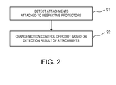
- Fig. 2 is a flowchart illustrating a changing procedure of a motion control of a robot 3 in the robot system 2.
- the robot system 2 includes the robot 3, an attachment detecting means 5, a motion-control changing means 6, and a motion controlling means 10.
- the robot 3 has an operable operation arm 4.
- operable refers to that the operation arm 4 can perform, for example, telescopic, extending and/or flexing, and/or turning operations by an actuator for converting energy, such as electric power or hydraulic pressure, into a physical motion of the operation arm 4.
- the motion controlling means 10 controls the operations of the robot 3 and the operation arm 4.
- the motion controlling means 10 outputs an operation instruction to the actuator of the operation arm 4 according to a preset operation program, and it monitors the positional information and the like of the actuator to control the operation arm 4 to carry out an operation according to the operation instruction.
- the motion controlling means 10 changes an operating speed of the operation arm 4 or stops the operation arm 4 according to an instruction from the motion-control changing means 6 (described later).
- the robot system 2 has a memory (not illustrated) for storing the operation program and parameters required for the control.
- the robot 3 operates at a speed specified by the preset operation program when a movable body 9 (described later) does not exist in the circumference thereof.
- the movable body 9 equips with (or wear) one or more protectors 7, and an attachment 8 is attached to each protector 7.
- An attachment detecting means 5 detects the attachment(s) 8 attached to the protector(s) 7.
- the motion-control changing means 6 instructs the motion controlling means 10 so that the motion control of the robot 3 is changed based on a result detected by the attachment detecting means 5.
- the robot system 2 first detects the attachment(s) 8 attached to the protector(s) 7 (S1: Attachment Detection). Next, the motion control of the robot 3 is changed based on the detection result(s) of the attachment(s) 8 (S2: Motion-control Change).
- the robot system 2 can change the motion control of the robot 3 according to a wearing state of the protector(s) 7 equipped or worn by the movable body 9 and, thus, safety can be improved.
- the term "wearing state” as used herein includes, for example, a case where the selection of the protector(s) 7 worn by the movable body 9 is not appropriate, and a case where the movable body 9 has forgotten to wear the protector(s) 7.
- the robot system 2 can change the motion control so that the operation is more restricted (for example, the speed of the robot 3 is reduced) so that the motion control is adapted to the current wearing state.
- the robot system 2 changes the motion control of the robot 3 according to the wearing state of the protector(s) 7 of the movable body 9, if the wearing state of the protector(s) 7 of the movable body 9 is appropriate, an excessive speed restriction and an excessive operational restriction of the robot 3 will be suppressed, a takt time will be shortened, and the productivity and availability of the robot 3 will be improved.
- the robot system 2 illustrated in Fig. 1 includes the robot 3 which is installed on a floor, a ceiling, a wall surface or the like, where the robot 3 has the articulated operation arm 4.
- the robot 3 is not limited to such a robot 3, as long as it has the operable operation arm 4.
- the robot 3 may have a pedestal for supporting the operation arm 4, and a moving mechanism for translating the pedestal within a predetermined range.
- the motion control by the motion controlling means 10 may include, in addition to the motion control of the operation arm, the motion control of the moving mechanism.
- movable body as used herein includes, for example, a person, a hand lift, a conveying carrier, and a self-propellable robot other than the robot 3.
- protecting refers to an article that can be equipped or worn by the movable body 9.
- the movable body 9 wears the protector(s) for the purpose of safety measures.
- the protector(s) 7 protect body part(s) of the person, respectively.
- the attachment 8 is attached to each of the protectors 7.
- the attachment 8 may store information on the protector 7 to which the attachment 8 concerned is attached, or a code (identifier) which is obtained by converting the information according to a certain rule. Note that these information are collectively referred to as "the information on the protector(s)."
- the movable body 9 is a person, and the person wears the helmet 7a and the safety shoes 7b, as the wearing articles or the protectors 7.
- IC tags 8a and 8b which store the information on the respective protectors 7 are attached to the helmet 7a and the safety shoes 7b, respectively, as attaching components or the attachments 8.
- the protectors 7 may include, other than the helmet 7a and the safety shoes 7b, for example, the gloves, the goggles, the protective clothing, a mask, and a neck protector.
- the information on the protector(s) may be a bar code related to the protector(s).
- the attachment 8 may be configured so that the existence of the protector 7 is detected by the attachment detecting means 5, instead of the attachment 8 having the information on the protector 7.
- the IC tag 8a having the information on the helmet 7a is attached to the helmet 7a.
- the IC tag 8b having the information on the safety shoes 7b is attached to the safety shoes 7b.
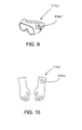
- the IC tag 8c having the information on goggles 7c is attached to the goggles 7c.
- the IC tag 8d having the information on gloves 7d is attached to the gloves 7d.
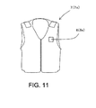
- the IC tag 8e having the information on protective clothing 7e is attached to the protective clothing 7e.
- the attachment detecting means 5 may read data from the IC tags (attachments) 8 and detect the existence and types of the protectors 7.
- Such an attachment detecting means 5 may include an IC tag reader 5a which reads the data from the IC tags 8.
- the attachment detecting means 5 has a gate 5b through which the movable body 9 passes, and the IC tag reader 5a disposed at the gate 5b.
- an attachment detecting means 5 when the movable body 9 passes through the gate 5b, the data stored in the IC tags 8 attached to the protectors 7 can certainly be read by the IC tag reader 5a.
- the attachment detecting means 5 may verify the bar codes (printing is also possible) attached to the protectors to detect the existence and types of the protectors.
- Such an attachment detecting means 5 may include a bar code reader.
- the motion-control changing means 6 outputs an instruction to the motion controlling means 10 based on the detection result of the attachment detecting means 5.
- the motion controlling means 10 changes the motion control of the robot 3 in response to the instruction.
- the motion-control changing means 6 may includes a detection information receiver 6a for receiving detection information from the attachment detecting means 5, a motion-control selector 6b for selecting the motion control of the robot 3 which is suitable for the wearing state of the protector(s) 7 of the movable body 9 based on the detection information received by the detection information receiver 6a, and a motion-control transmitter 6c for transmitting a selected motion control to the motion controlling means 10.
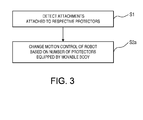
- Fig. 3 is a flowchart illustrating a changing procedure of the motion control of the robot 3, in a robot system according to Modification 1 of the above embodiment.
- the motion-control changing means 6 changes the motion control of the robot 3 based on the number of protectors 7 worn by the movable body 9, in other words, based on the number of protectors 7 detected by the attachment detecting means 5.
- the attachments 8 attached to the respective protectors 7 are detected (S1: Attachment Detection).
- the method of detecting the attachments is similar to that of the robot system 2 according to Embodiment 1.
- the motion control of the robot 3 is changed based on the number of protectors 7 (S2a: Motion-control Change).
- the restrictions on the speed and operation of the robot 3 may be loosened.
- the restrictions on the speed and operation of the robot 3 may be tightened.
- the motion control of the robot 3 can appropriately be changed according to the wearing state of the protectors 7 of the movable body 9. Since other configurations of the robot system according to Modification 1 are similar to those of the robot system 2 according to Embodiment 1, the description thereof is omitted.
- Fig. 4 is a flowchart illustrating a changing procedure of the motion control of the robot 3, in a robot system according to Modification 2 of Embodiment 1.
- the motion-control changing means 6 determines a wearing level of the movable body 9 based on a weighting value defined for each type of the protectors 7, and then changes the motion control of the robot 3 based on the wearing level.
- the attachments 8 attached to the respective protectors 7 are detected (S1: Attachment Detection).
- the method of detecting the attachments 8 is similar to that of the robot system 2 according to Embodiment 1.
- the motion-control changing means 6 determines the wearing level of the movable body 9 based on the weighting value (S2b: Motion-control Change).
- the motion-control changing means 6 changes the motion control of the robot 3 based on the wearing level (S2c: Motion-control Change).
- the wearing level is appropriate, the restrictions on the speed and operation of the robot 3 are decreased, the takt time is shortened, and the productivity and availability of the robot 3 improves.
- the weighting value can be obtained by converting the safety level of the protector into a numerical value. For example, it is possible to adopt a weighting system where ten points are maximum, where one protector 7 which needs less protection may be assigned with one point, and another protector 7 which needs higher protection may be assigned with ten points.
- the term the "protector which needs higher protection” refers to a protector, for example, which protects the person's head and/or eyes, and which induces a higher risk of the safety if the person is not wearing them.
- a protector may include the helmet and/or a visor (or protective eyeglasses).
- the "protector which needs less protection” refers to a protector, for example, of which the safety risks by not wearing is lower than the "protector which needs higher protection.”
- the "protector which needs less protection” may include the safety shoes and/or the gloves.
- the weighting value may be differentiated according to the characteristics of the protectors 7 if the characteristics of the protector 7 differ from each other.
- the weighting value of the helmet having the visor which protects the eyes may be different from the weighting value of the helmet without such a visor.
- the weighting value of the protector 7 may be defined according to a wearing location of the protector 7 on the movable body 9. For example, as for the protector 7 worn on a part of the movable body 9 where comparatively serious damages may be caused when the robot 3 interferes with the movable body 9, a larger weighting value may be given to this protector 7.
- the helmet worn on the person's head may be given a larger weighting value than other types of protector.
- the safety can be improved by defining the weighting value and setting the wearing level of the movable body as described above.
- the wearing level may be calculated based on the total value of the weighting values of the protectors 7 worn by the movable body 9. That is, the wearing level is higher as the total value of the weighting values increases and, thus, the safety measures of the movable body 9 is improved.
- an average value may be calculated by dividing the total value of the weighting values by the number of protectors 7 worn by the movable body 9, and the wearing level may be calculated based on the average value of the weighting values.
- the weighting value and the wearing level of the protector 7 can suitably be set according to how the robot 3 is operated. Since other configurations of the robot system according to Modification 2 are similar to those of the robot system according to Embodiment 1, the description thereof is omitted.
- Fig. 5 is a flowchart illustrating a changing procedure of the motion control of the robot 3, in a robot system according to Modification 3 of Embodiment 1.
- the motion-control changing means 6 selects a specific motion control when the protector 7 does not satisfy a predetermined condition.
- specific motion control refers to at least any one of, for example, a stop of the operation of the robot 3, a reduction in the operating speed of the robot 3, a reduction in the output of the actuator of the robot 3, and a reduction in the operating range of the robot 3.
- the attachments 8 attached to the protectors 7 are detected (S1: Attachment Detection).
- the method of detecting the attachments 8 is similar to that of the robot system 2 according to Embodiment 1.
- the motion-control changing means 6 determines whether the protector 7 satisfies the predetermined condition (S2d: Motion-control Change). When the predetermined condition is satisfied, the motion-control changing means 6 changes the motion control of the robot 3 based on the detection results of the attachments 8 (S2f: Motion-control Change). On the other hand, when the predetermined condition is not satisfied, the motion-control changing means 6 selects the specific motion control (S2e: Motion-control Change).
- the specific motion control is, for example, to reduce the interference of the robot 3 with the movable body 9, and the risk at the time of the interference of the robot 3 with the movable body 9, and the safety can be increased by an appropriate selection of the motion control.
- the predetermined condition is preferred to be set based on whether sufficient safety is secured with the protectors 7 worn by the movable body 9, with respect to the way of operation of the robot 3.
- the number of protectors 7 may be used as the setting criterion of the predetermined condition.
- the wearing level reached a predetermined wearing level may be used as the setting criterion of the predetermined condition. Since other configurations of the robot system according to Modification 3 are similar to those of the robot system according to Embodiment 1, the description thereof is omitted.
- Fig. 6 is a flowchart illustrating a changing procedure of the motion control of the robot 3, in a robot system according to Modification 4 of Embodiment 1.
- the motion-control changing means 6 performs the specific motion control when a specific attachment is not detected.
- the term "specific motion control" as used herein refers to at least any one of, for example, a stop of the operation of the robot 3, an issue of alert, a reduction in the operating speed of the robot 3, a reduction in the output of the actuator of the robot 3, and a reduction in the operating range of the robot 3.
- the attachments 8 attached to the protectors 7 are detected (S1: Attachment Detection).
- the method of detecting the attachments 8 is similar to that of the robot system 2 according to Embodiment 1.
- the motion-control changing means 6 determines whether the specific attachment 8 is detected (S2g: Motion-control Change).
- the motion-control changing means 6 changes the motion control of the robot 3 based on the detection results of the attachments 8 at Step S 1 (S2i: Motion-control Change).
- the motion-control changing means 6 performs the specific motion control (S2h: Motion-control Change).
- the safety can be improved by reducing, for example, the interference of the robot 3 with the movable body 9, and the risk at the time of interfering the robot 3 with the movable body 9.
- the term "specific attachment" as used herein includes the protector 7 worn at a part of the movable body 9 where comparatively serious damages may be caused when the robot 3 interferes with the movable body 9.
- the protector is the helmet worn on the person's head.
- a generation of comparatively serious damages can be reduced, or a warning of the generation of the damages can be performed. Since other configurations of the robot system according to Modification 4 are similar to those of the robot system according to Embodiment 1, the description thereof is omitted.
- the method of controlling the robot system according to Embodiment 2 is the method of controlling the robot system 2 according to the embodiment 1 illustrated in Fig. 1 .
- This controlling method includes an attachment detection step and a motion-control change step.
- the attachment detection step is a step which detects the attachment(s) 8 attached to one or more protectors 7 worn by the movable body 9 as illustrated in Fig. 1 .
- the motion-control change step is a step which changes the motion control of the robot 3 having the operable operation arm 4 based on the detection result(s) obtained by the attachment detection step.
- a flow of the control in the method of controlling the robot system according to Embodiment 2 is described sequentially.
- the attachment detection step S1 the attachments 8 attached to the protectors 7 are detected.
- the motion-control change step S2 the motion control of the robot 3 having the operable operation arm 4 is changed based on the detection result(s) obtained by attachment detection step S1. According to such a method of controlling the robot system, the safety can be improved.
- the motion control of the robot 3 is changed according to the wearing state of the protector(s) 7 of the movable body 9, the restrictions on the speed and operation of the robot 3 can be reduced, the takt time can be shortened, and the productivity and availability of the robot 3 can be improved.
- the method of controlling the robot system may be any one of the methods described in Modifications 2 to 4. That is, the attachment detection step and the motion-control change step may suitably be modified according to the configurations of the robot system of the respective modifications.
Landscapes
- Engineering & Computer Science (AREA)
- Mechanical Engineering (AREA)
- Robotics (AREA)
- General Engineering & Computer Science (AREA)
- Health & Medical Sciences (AREA)
- General Health & Medical Sciences (AREA)
- Orthopedic Medicine & Surgery (AREA)
- Radar, Positioning & Navigation (AREA)
- Remote Sensing (AREA)
- Manipulator (AREA)
Abstract
Description
- This disclosure relates to a robot system and a method of controlling the robot system.
- Conventionally, robots with an operable operation arm have been proposed. Normally, a safety fence is provided in the circumference of the operation arm to divide an operating range of the operation arm from an operating range of a person. However, for example, the person may enter inside the safety fence to supply objects to be processed.
- In recent years, cases where both the operation arm and the person work together within a space where there is no partition have been increased. In such a robot, certain safety measures are taken, for example, to avoid risks of interference of the robot with the person when the person enters into the operating range of the operation arm. For example,
JP4,219,870B2 - In the man-machine operation system disclosed in
JP4,219,870B2 - Alternatively, the safety measures for the person (operator) may include the person wearing protectors for protecting body parts of the person. Such protectors are often to protect the body parts of the person, such as a helmet for protecting the person's head and a pair of goggles for protecting the person's eyes, and various types of protector have been proposed.
- However, the protectors for the safety measures may not be appropriately selected, or the person (operator) may forget to wear the protectors. In addition, if the person enters into the operating range of the robot while the person is not wearing the appropriate protectors, the safety of the person may not fully be secured.
- This disclosure provides a robot system and a method of controlling the robot system, which improve safety.
- According to one aspect of the present disclosure, a robot system is provided, which includes a robot having an operable operation arm, an attachment detecting means for detecting one or more attachments, each attached to a wearing article equipped by a movable body, and a motion-control changing means for changing a motion control of the robot based on a detection result detected by the attachment detecting means.
- The wearing article may be a protector for protecting the movable body.
- The robot may have an articulated operation arm.
- The robot may include a pedestal for supporting the operation arm, and a moving mechanism for moving the pedestal.
- The motion-control changing means may change the motion control based on the number of the wearing articles equipped by the movable body.
- The motion-control changing means may set a wearing level of the movable body based on a weighting value defined for each type of the wearing articles, and may change the motion control based on the wearing level.
- The motion-control changing means may select, when the wearing article equipped by the movable body does not satisfy a predetermined condition, at least any one of the motion controls including a stop of an operation of the robot, a reduction in an operating speed of the robot, a reduction in an output of an actuator of the robot, and a reduction in an operating range of the robot.
- The motion-control changing means may perform, when a specific attachment is not detected, at least any one of a stop of an operation of the robot, an issue of an alert, a reduction in an operating speed of the robot, a reduction in an output of an actuator of the robot, and a reduction in an operating range of the robot.
- The attachment detecting means may read data from an IC tag attached to each wearing article to detect the existence and types of the wearing articles.
- The attachment detecting means may verify a bar code attached to each wearing article to detect the existence and types of the wearing articles.
- The attachment detecting means may have a gate through which the movable body passes, and a detector disposed at the gate and for detecting the attachment.
- The attachment detecting means may further have a safety fence surrounding the circumference of the robot system, and the gate may be disposed so that the movable body can enter into and exit the safety fence only by passes passing through the gate.
- According to another aspect of the present disclosure, a method of controlling a robot system is provided, which includes detecting one or more attachments, each attached to a wearing article equipped by a movable body, and changing a motion control of the robot having an operable operation arm, based on the detection result.
- According to this disclosure, the safety can be improved.
- Further purposes or other features of the present invention will be apparent below from preferable embodiments described with reference to the accompanying drawings.
- The present disclosure is illustrated by way of example and not by way of limitation in the figures of the accompanying drawings, in which the like reference numeral indicate like elements and in which:
-
Fig. 1 is a schematic diagram illustrating a robot system according toEmbodiment 1; -
Fig. 2 is a flowchart illustrating a changing procedure of a motion control of a robot in the robot system ofFig. 1 ; -
Fig. 3 is aflowchart illustrating Modification 1 of the procedure ofFig. 2 ; -
Fig. 4 is aflowchart illustrating Modification 2 of the procedure ofFig. 2 ; -
Fig. 5 is a flowchart illustrating Modification 3 of the procedure ofFig. 2 ; -
Fig. 6 is a flowchart illustrating Modification 4 of the procedure ofFig. 2 ; -
Fig. 7 is a schematic diagram illustrating a helmet to which an IC tag is attached, where the IC tag has information on the helmet; -
Fig. 8 is a schematic diagram illustrating a pair of safety shoes to which an IC tag is attached, where the IC tag has information on the safety shoes; -
Fig. 9 is a schematic diagram illustrating a pair of goggles to which an IC tag is attached, where the IC tag has information on the goggles; -
Fig. 10 is a schematic diagram illustrating a pair of gloves to which an IC tag is attached, where the IC tag has information on the gloves; and -
Fig. 11 is a schematic diagram illustrating protective clothing to which an IC tag is attached, where the IC tag has information on the protective clothing. - Hereinafter, robot systems according to several embodiments will be described using the accompanying drawings.
-
Fig. 1 is a schematic diagram illustrating arobot system 2 according toEmbodiment 1.Fig. 2 is a flowchart illustrating a changing procedure of a motion control of a robot 3 in therobot system 2. - As illustrated in
Fig. 1 , therobot system 2 includes the robot 3, an attachment detecting means 5, a motion-control changing means 6, and a motion controlling means 10. The robot 3 has an operable operation arm 4. The term "operable" as used herein refers to that the operation arm 4 can perform, for example, telescopic, extending and/or flexing, and/or turning operations by an actuator for converting energy, such as electric power or hydraulic pressure, into a physical motion of the operation arm 4. - The motion controlling means 10 controls the operations of the robot 3 and the operation arm 4. The motion controlling means 10 outputs an operation instruction to the actuator of the operation arm 4 according to a preset operation program, and it monitors the positional information and the like of the actuator to control the operation arm 4 to carry out an operation according to the operation instruction. In addition, the motion controlling means 10 changes an operating speed of the operation arm 4 or stops the operation arm 4 according to an instruction from the motion-control changing means 6 (described later).
- Note that the
robot system 2 has a memory (not illustrated) for storing the operation program and parameters required for the control. - The robot 3 operates at a speed specified by the preset operation program when a movable body 9 (described later) does not exist in the circumference thereof.
- The movable body 9 equips with (or wear) one or
more protectors 7, and anattachment 8 is attached to eachprotector 7. An attachment detecting means 5 detects the attachment(s) 8 attached to the protector(s) 7. The motion-control changing means 6 instructs the motion controlling means 10 so that the motion control of the robot 3 is changed based on a result detected by the attachment detecting means 5. In detail, as illustrated inFig. 2 , therobot system 2 first detects the attachment(s) 8 attached to the protector(s) 7 (S1: Attachment Detection). Next, the motion control of the robot 3 is changed based on the detection result(s) of the attachment(s) 8 (S2: Motion-control Change). - As illustrated in
Fig. 1 , therobot system 2 can change the motion control of the robot 3 according to a wearing state of the protector(s) 7 equipped or worn by the movable body 9 and, thus, safety can be improved. The term "wearing state" as used herein includes, for example, a case where the selection of the protector(s) 7 worn by the movable body 9 is not appropriate, and a case where the movable body 9 has forgotten to wear the protector(s) 7. Therobot system 2 can change the motion control so that the operation is more restricted (for example, the speed of the robot 3 is reduced) so that the motion control is adapted to the current wearing state. Further, since therobot system 2 changes the motion control of the robot 3 according to the wearing state of the protector(s) 7 of the movable body 9, if the wearing state of the protector(s) 7 of the movable body 9 is appropriate, an excessive speed restriction and an excessive operational restriction of the robot 3 will be suppressed, a takt time will be shortened, and the productivity and availability of the robot 3 will be improved. - The
robot system 2 illustrated inFig. 1 includes the robot 3 which is installed on a floor, a ceiling, a wall surface or the like, where the robot 3 has the articulated operation arm 4. The robot 3 is not limited to such a robot 3, as long as it has the operable operation arm 4. For example, although illustration is omitted, the robot 3 may have a pedestal for supporting the operation arm 4, and a moving mechanism for translating the pedestal within a predetermined range. In such a robot system provided with the robot having the moving mechanism, the motion control by the motion controlling means 10 may include, in addition to the motion control of the operation arm, the motion control of the moving mechanism. - The term "movable body" as used herein includes, for example, a person, a hand lift, a conveying carrier, and a self-propellable robot other than the robot 3. The term "protector" as used herein refers to an article that can be equipped or worn by the movable body 9. For example, the movable body 9 wears the protector(s) for the purpose of safety measures. For example, if the movable body 9 is a person, the protector(s) 7 protect body part(s) of the person, respectively.
- As described above, the
attachment 8 is attached to each of theprotectors 7. Theattachment 8 may store information on theprotector 7 to which theattachment 8 concerned is attached, or a code (identifier) which is obtained by converting the information according to a certain rule. Note that these information are collectively referred to as "the information on the protector(s)." - In
Fig. 1 , the movable body 9 is a person, and the person wears thehelmet 7a and thesafety shoes 7b, as the wearing articles or theprotectors 7. In addition, IC tags 8a and 8b which store the information on therespective protectors 7 are attached to thehelmet 7a and thesafety shoes 7b, respectively, as attaching components or theattachments 8. Although illustration is omitted, theprotectors 7 may include, other than thehelmet 7a and thesafety shoes 7b, for example, the gloves, the goggles, the protective clothing, a mask, and a neck protector. Alternatively, "the information on the protector(s)" may be a bar code related to the protector(s). Contrary, theattachment 8 may be configured so that the existence of theprotector 7 is detected by theattachment detecting means 5, instead of theattachment 8 having the information on theprotector 7. - In
Fig. 7 , theIC tag 8a having the information on thehelmet 7a is attached to thehelmet 7a. Alternatively, inFig. 8 , theIC tag 8b having the information on thesafety shoes 7b is attached to thesafety shoes 7b. Alternatively, inFig. 9 , theIC tag 8c having the information ongoggles 7c is attached to thegoggles 7c. Alternatively, inFig. 10 , theIC tag 8d having the information ongloves 7d is attached to thegloves 7d. Alternatively, inFig. 11 , theIC tag 8e having the information onprotective clothing 7e is attached to theprotective clothing 7e. - Accordingly, as illustrated in
Fig. 1 , theattachment detecting means 5 may read data from the IC tags (attachments) 8 and detect the existence and types of theprotectors 7. Such anattachment detecting means 5 may include anIC tag reader 5a which reads the data from the IC tags 8. Note that, inFig. 1 , theattachment detecting means 5 has agate 5b through which the movable body 9 passes, and theIC tag reader 5a disposed at thegate 5b. - Although illustration is omitted, it may also be configured so that the circumference of the
robot system 2 is surrounded by a safety fence coupled with thegate 5b provided with theIC tag reader 5a, and the movable body 9 is forced to pass through thegate 5b when approaching therobot system 2. According to such anattachment detecting means 5, when the movable body 9 passes through thegate 5b, the data stored in the IC tags 8 attached to theprotectors 7 can certainly be read by theIC tag reader 5a. Although illustration is omitted, theattachment detecting means 5 may verify the bar codes (printing is also possible) attached to the protectors to detect the existence and types of the protectors. Such anattachment detecting means 5 may include a bar code reader. - As illustrated in
Fig. 1 , the motion-control changing means 6 outputs an instruction to the motion controlling means 10 based on the detection result of theattachment detecting means 5. The motion controlling means 10 changes the motion control of the robot 3 in response to the instruction. The motion-control changing means 6 may includes adetection information receiver 6a for receiving detection information from theattachment detecting means 5, a motion-control selector 6b for selecting the motion control of the robot 3 which is suitable for the wearing state of the protector(s) 7 of the movable body 9 based on the detection information received by thedetection information receiver 6a, and a motion-control transmitter 6c for transmitting a selected motion control to the motion controlling means 10. - The above embodiment is merely one example of this disclosure, and can be modified as follows.
-
Fig. 3 is a flowchart illustrating a changing procedure of the motion control of the robot 3, in a robot system according toModification 1 of the above embodiment. In the robot system according toModification 1, the motion-control changing means 6 changes the motion control of the robot 3 based on the number ofprotectors 7 worn by the movable body 9, in other words, based on the number ofprotectors 7 detected by theattachment detecting means 5. - In detail, as illustrated in
Fig. 3 , first, theattachments 8 attached to therespective protectors 7 are detected (S1: Attachment Detection). Here, the method of detecting the attachments is similar to that of therobot system 2 according toEmbodiment 1. Next, the motion control of the robot 3 is changed based on the number of protectors 7 (S2a: Motion-control Change). - For example, it can be said that the safety of the movable body 9 is secured at a higher level as the number of the
protectors 7 worn by the movable body 9 increases. Therefore, the restrictions on the speed and operation of the robot 3 may be loosened. For example, it is possible to operate the robot at a speed near the operating speed set by the operation program. On the other hand, since it can be said that the movable body 9 is less secured as the number of theprotectors 7 worn by the movable body 9 decreases, the restrictions on the speed and operation of the robot 3 may be tightened. For example, it is possible to operate the robot 3 at a speed which is slower than a half the operating speed set by the operation program. Thus, since the criterion to select the motion control of the robot 3 is based on the number of theprotectors 7 detected by theattachment detecting means 5, the motion control of the robot 3 can appropriately be changed according to the wearing state of theprotectors 7 of the movable body 9. Since other configurations of the robot system according toModification 1 are similar to those of therobot system 2 according toEmbodiment 1, the description thereof is omitted. -
Fig. 4 is a flowchart illustrating a changing procedure of the motion control of the robot 3, in a robot system according toModification 2 ofEmbodiment 1. In the robot system according toModification 2, the motion-control changing means 6 determines a wearing level of the movable body 9 based on a weighting value defined for each type of theprotectors 7, and then changes the motion control of the robot 3 based on the wearing level. - In detail, as illustrated in
Fig. 4 , first, theattachments 8 attached to therespective protectors 7 are detected (S1: Attachment Detection). Here, the method of detecting theattachments 8 is similar to that of therobot system 2 according toEmbodiment 1. Next, the motion-control changing means 6 determines the wearing level of the movable body 9 based on the weighting value (S2b: Motion-control Change). Next, the motion-control changing means 6 changes the motion control of the robot 3 based on the wearing level (S2c: Motion-control Change). Thus, if the wearing level is appropriate, the restrictions on the speed and operation of the robot 3 are decreased, the takt time is shortened, and the productivity and availability of the robot 3 improves. The weighting value can be obtained by converting the safety level of the protector into a numerical value. For example, it is possible to adopt a weighting system where ten points are maximum, where oneprotector 7 which needs less protection may be assigned with one point, and anotherprotector 7 which needs higher protection may be assigned with ten points. - Note that the term the "protector which needs higher protection" refers to a protector, for example, which protects the person's head and/or eyes, and which induces a higher risk of the safety if the person is not wearing them. Such a protector may include the helmet and/or a visor (or protective eyeglasses). On the other hand, the "protector which needs less protection" refers to a protector, for example, of which the safety risks by not wearing is lower than the "protector which needs higher protection." The "protector which needs less protection" may include the safety shoes and/or the gloves.
- Alternatively, even for the same type of
protectors 7, the weighting value may be differentiated according to the characteristics of theprotectors 7 if the characteristics of theprotector 7 differ from each other. For example, if theprotector 7 is the helmet, the weighting value of the helmet having the visor which protects the eyes may be different from the weighting value of the helmet without such a visor. Further, the weighting value of theprotector 7 may be defined according to a wearing location of theprotector 7 on the movable body 9. For example, as for theprotector 7 worn on a part of the movable body 9 where comparatively serious damages may be caused when the robot 3 interferes with the movable body 9, a larger weighting value may be given to thisprotector 7. Specifically, the helmet worn on the person's head may be given a larger weighting value than other types of protector. Thus, the safety can be improved by defining the weighting value and setting the wearing level of the movable body as described above. - The wearing level may be calculated based on the total value of the weighting values of the
protectors 7 worn by the movable body 9. That is, the wearing level is higher as the total value of the weighting values increases and, thus, the safety measures of the movable body 9 is improved. Alternatively, an average value may be calculated by dividing the total value of the weighting values by the number ofprotectors 7 worn by the movable body 9, and the wearing level may be calculated based on the average value of the weighting values. Thus, for example, when the movable body 9 wears a number ofprotectors 7 with lower weighting values, an excessive increase in the wearing level can be suppressed. The weighting value and the wearing level of theprotector 7 can suitably be set according to how the robot 3 is operated. Since other configurations of the robot system according toModification 2 are similar to those of the robot system according toEmbodiment 1, the description thereof is omitted. -
Fig. 5 is a flowchart illustrating a changing procedure of the motion control of the robot 3, in a robot system according to Modification 3 ofEmbodiment 1. In the robot system according to Modification 3, the motion-control changing means 6 selects a specific motion control when theprotector 7 does not satisfy a predetermined condition. The term "specific motion control" as used herein refers to at least any one of, for example, a stop of the operation of the robot 3, a reduction in the operating speed of the robot 3, a reduction in the output of the actuator of the robot 3, and a reduction in the operating range of the robot 3. - In detail, as illustrated in
Fig. 5 , first, theattachments 8 attached to theprotectors 7 are detected (S1: Attachment Detection). Here, the method of detecting theattachments 8 is similar to that of therobot system 2 according toEmbodiment 1. Next, the motion-control changing means 6 determines whether theprotector 7 satisfies the predetermined condition (S2d: Motion-control Change). When the predetermined condition is satisfied, the motion-control changing means 6 changes the motion control of the robot 3 based on the detection results of the attachments 8 (S2f: Motion-control Change). On the other hand, when the predetermined condition is not satisfied, the motion-control changing means 6 selects the specific motion control (S2e: Motion-control Change). - The specific motion control is, for example, to reduce the interference of the robot 3 with the movable body 9, and the risk at the time of the interference of the robot 3 with the movable body 9, and the safety can be increased by an appropriate selection of the motion control.
- Further, although there is no limitation in particular for the predetermined condition, the predetermined condition is preferred to be set based on whether sufficient safety is secured with the
protectors 7 worn by the movable body 9, with respect to the way of operation of the robot 3. For example, when changing the motion control of the robot 3 based on the number of protectors, the number ofprotectors 7 may be used as the setting criterion of the predetermined condition. Alternatively, when setting the wearing level of the movable body 9 based on the weighting value, the wearing level reached a predetermined wearing level may be used as the setting criterion of the predetermined condition. Since other configurations of the robot system according to Modification 3 are similar to those of the robot system according toEmbodiment 1, the description thereof is omitted. -
Fig. 6 is a flowchart illustrating a changing procedure of the motion control of the robot 3, in a robot system according to Modification 4 ofEmbodiment 1. In the robot system according to Modification 4, the motion-control changing means 6 performs the specific motion control when a specific attachment is not detected. The term "specific motion control" as used herein refers to at least any one of, for example, a stop of the operation of the robot 3, an issue of alert, a reduction in the operating speed of the robot 3, a reduction in the output of the actuator of the robot 3, and a reduction in the operating range of the robot 3. - In detail, as illustrated in
Fig. 6 , first, theattachments 8 attached to theprotectors 7 are detected (S1: Attachment Detection). Here, the method of detecting theattachments 8 is similar to that of therobot system 2 according toEmbodiment 1. Next, the motion-control changing means 6 determines whether thespecific attachment 8 is detected (S2g: Motion-control Change). When thespecific attachment 8 is detected, the motion-control changing means 6 changes the motion control of the robot 3 based on the detection results of theattachments 8 at Step S 1 (S2i: Motion-control Change). On the other hand, when the specific attachment is not detected, the motion-control changing means 6 performs the specific motion control (S2h: Motion-control Change). - Thus, the safety can be improved by reducing, for example, the interference of the robot 3 with the movable body 9, and the risk at the time of interfering the robot 3 with the movable body 9. The term "specific attachment" as used herein includes the
protector 7 worn at a part of the movable body 9 where comparatively serious damages may be caused when the robot 3 interferes with the movable body 9. Specifically, the protector is the helmet worn on the person's head. Thus, a generation of comparatively serious damages can be reduced, or a warning of the generation of the damages can be performed. Since other configurations of the robot system according to Modification 4 are similar to those of the robot system according toEmbodiment 1, the description thereof is omitted. - Hereinafter, a method of controlling a robot system according to
Embodiment 2 is described. The method of controlling the robot system according toEmbodiment 2 is the method of controlling therobot system 2 according to theembodiment 1 illustrated inFig. 1 . This controlling method includes an attachment detection step and a motion-control change step. The attachment detection step is a step which detects the attachment(s) 8 attached to one ormore protectors 7 worn by the movable body 9 as illustrated inFig. 1 . The motion-control change step is a step which changes the motion control of the robot 3 having the operable operation arm 4 based on the detection result(s) obtained by the attachment detection step. - Next, based on the flowchart illustrated in
Fig. 2 , a flow of the control in the method of controlling the robot system according toEmbodiment 2 is described sequentially. First, in the attachment detection step S1, theattachments 8 attached to theprotectors 7 are detected. Next, at the motion-control change step S2, the motion control of the robot 3 having the operable operation arm 4 is changed based on the detection result(s) obtained by attachment detection step S1. According to such a method of controlling the robot system, the safety can be improved. In addition, since the motion control of the robot 3 is changed according to the wearing state of the protector(s) 7 of the movable body 9, the restrictions on the speed and operation of the robot 3 can be reduced, the takt time can be shortened, and the productivity and availability of the robot 3 can be improved. - Alternatively, the method of controlling the robot system may be any one of the methods described in
Modifications 2 to 4. That is, the attachment detection step and the motion-control change step may suitably be modified according to the configurations of the robot system of the respective modifications. - In the foregoing specification and specific embodiments of the present invention have been described. However, one of ordinary skill in the art appreciates that various modifications and changes can be made without departing from the scope of the present invention as set forth in the claims below. Accordingly and the specification and figures are to be regarded in an illustrative rather than a restrictive sense, and all such modifications are intended to be included within the scope of present invention. The benefits and advantages, solutions to problems, and any element(s) that may cause any benefit, advantage and or solution to occur or become more pronounced are not to be construed as a critical, required and or essential features or elements of any or all the claims. The invention is defined solely by the appended claims including any amendments made during the pendency of this application and all equivalents of those claims as issued.
Claims (13)
- A robot system (2), comprising:a robot (3) having an operable operation arm (4);an attachment detecting means (5, 5a, 5b) for detecting one or more attachments (8, 8a, 8b), each attached to a wearing article (7, 7a, 7b) equipped by a movable body (9); anda motion-control changing means (6) for changing a motion control of the robot (3) based on a detection result detected by the attachment detecting means (5, 5a, 5b).
- The robot system (2) of claim 1, wherein the wearing article (7, 7a, 7b) is a protector for protecting the movable body (9).
- The robot system (2) of claim 1 or 2, wherein the robot (3) has an articulated operation arm (4).
- The robot system (2) of any one of claims 1 to 3, wherein the robot (3) includes a pedestal for supporting the operation arm (4), and a moving mechanism for moving the pedestal.
- The robot system of any one of claims 1 to 4, wherein the motion-control changing means (6) changes the motion control based on the number of the wearing articles (7, 7a, 7b) equipped by the movable body (9).
- The robot system (2) of any one of claims 1 to 4, wherein the motion-control changing means (6) sets a wearing level of the movable body (9) based on a weighting value defined for each type of the wearing articles (7, 7a, 7b), and changes the motion control based on the wearing level.
- The robot system (2) of any one of claims 1 to 6, wherein the motion-control changing means (6) selects, when the wearing article (7, 7a, 7b) equipped by the movable body (9) does not satisfy a predetermined condition, at least any one of the motion controls including a stop of an operation of the robot (3), a reduction in an operating speed of the robot (3), a reduction in an output of an actuator of the robot (3), and a reduction in an operating range of the robot (3).
- The robot system (2) of any one of claims 1 to 7, wherein the motion-control changing means (6) performs, when a specific attachment is not detected, at least any one of a stop of an operation of the robot (3), an issue of an alert, a reduction in an operating speed of the robot (3), a reduction in an output of an actuator of the robot (3), and a reduction in an operating range of the robot (3).
- The robot system (2) of any one of claims 1 to 8, wherein the attachment detecting means (5, 5a) reads data from an IC tag (8a, 8b) attached to each wearing article (7a, 7b) to detect the existence and types of the wearing article (7a, 7b).
- The robot system (2) of any one of claims 1 to 8, wherein the attachment detecting means (5) verifies a bar code attached to each wearing article (7, 7a, 7b) to detect the existence and types of the wearing articles (7, 7a, 7b).
- The robot system (2) of any one of claims 1 to 10, wherein the attachment detecting means (5, 5a, 5b) has a gate (5b) through which the movable body (9) passes, and a detector (5a) disposed at the gate (5b) and for detecting the attachment (8, 8a, 8b).
- The robot system (2) of claim 11, wherein the attachment detecting means (5, 5a, 5b) further has a safety fence surrounding the circumference of the robot system (2), and the gate (5b) is disposed so that the movable body (9) can enter into and exit the safety fence only by passes passing through the gate (5b).
- A method of controlling a robot system (2), comprising:detecting (S1) one or more attachments (8, 8a, 8b), each attached to a wearing article (7, 7a, 7b) equipped by a movable body (9); andchanging (S2, S2a-S2i) a motion control of the robot (3) having an operable operation arm (4), based on the detection result.
Applications Claiming Priority (1)
| Application Number | Priority Date | Filing Date | Title |
|---|---|---|---|
| JP2013054603A JP5846145B2 (en) | 2013-03-18 | 2013-03-18 | Robot system and control method of robot system |
Publications (2)
| Publication Number | Publication Date |
|---|---|
| EP2783811A2 true EP2783811A2 (en) | 2014-10-01 |
| EP2783811A3 EP2783811A3 (en) | 2016-04-13 |
Family
ID=50396856
Family Applications (1)
| Application Number | Title | Priority Date | Filing Date |
|---|---|---|---|
| EP14159045.5A Withdrawn EP2783811A3 (en) | 2013-03-18 | 2014-03-12 | Robot system and method of controlling the robot system |
Country Status (4)
| Country | Link |
|---|---|
| US (1) | US9126334B2 (en) |
| EP (1) | EP2783811A3 (en) |
| JP (1) | JP5846145B2 (en) |
| CN (1) | CN104057444B (en) |
Cited By (2)
| Publication number | Priority date | Publication date | Assignee | Title |
|---|---|---|---|---|
| CN106808496A (en) * | 2015-11-25 | 2017-06-09 | 电装波动株式会社 | Robot security's system |
| WO2017093289A3 (en) * | 2015-12-01 | 2017-07-27 | Bragi GmbH | Robotic safety using wearables |
Families Citing this family (19)
| Publication number | Priority date | Publication date | Assignee | Title |
|---|---|---|---|---|
| US12350830B2 (en) | 2013-09-27 | 2025-07-08 | Barrett Technology, Llc | Multi-active-axis, non-exoskeletal rehabilitation device |
| CN105979919B (en) | 2013-09-27 | 2019-09-20 | 埃斯顿(南京)医疗科技有限公司 | Non-exoskeleton rehabilitation equipment with multiple active axes |
| WO2017059359A2 (en) * | 2015-09-30 | 2017-04-06 | Barrett Technology, Llc | Multi-active-axis, non-exoskeletal rehabilitation device |
| US12447089B2 (en) | 2013-09-27 | 2025-10-21 | Barrett Technology, Llc | Multi-active-axis, non-exoskeletal robotic rehabilitation device |
| US9588519B2 (en) * | 2015-03-17 | 2017-03-07 | Amazon Technologies, Inc. | Systems and methods to facilitate human/robot interaction |
| US9649766B2 (en) * | 2015-03-17 | 2017-05-16 | Amazon Technologies, Inc. | Systems and methods to facilitate human/robot interaction |
| CN106293042B (en) * | 2015-06-26 | 2020-06-23 | 联想(北京)有限公司 | Information processing method and electronic equipment |
| US10198706B2 (en) * | 2015-07-31 | 2019-02-05 | Locus Robotics Corp. | Operator identification and performance tracking |
| EP3337419B1 (en) * | 2015-08-19 | 2020-08-12 | Brainlab AG | Reference array holder |
| JP6778199B2 (en) * | 2015-08-25 | 2020-10-28 | 川崎重工業株式会社 | Remote control robot system |
| AU2015417240A1 (en) * | 2015-12-14 | 2018-07-05 | Gustav Klauke Gmbh | Motor-driven hand-held tool, method for using a hand-held tool, combination of a motor-driven hand-held tool and glove |
| SG11201805378XA (en) * | 2016-01-04 | 2018-07-30 | Zhejiang Libiao Robots Co Ltd | Method and device for returning robots from site |
| JP6525922B2 (en) * | 2016-05-19 | 2019-06-05 | 三菱電機株式会社 | Touch panel control device, touch panel device, display device, electronic device and IC tag |
| CN107581713B (en) * | 2016-07-07 | 2020-04-14 | 宝成工业股份有限公司 | Automated shoelacing system |
| US11000953B2 (en) * | 2016-08-17 | 2021-05-11 | Locus Robotics Corp. | Robot gamification for improvement of operator performance |
| EP3406407A1 (en) * | 2017-05-26 | 2018-11-28 | Syddansk Universitet | Robot system with adaptive motion performance |
| US9895265B1 (en) | 2017-06-30 | 2018-02-20 | Safe Tool Technology Corporation | Safety apparatus and system for use with eye protection |
| WO2020013322A1 (en) * | 2018-07-13 | 2020-01-16 | Ntn株式会社 | Robot personal protection device |
| BR112021009651A2 (en) | 2018-11-20 | 2021-08-17 | Transocean Sedco Forex Ventures Limited | proximity-based personnel security system and method |
Citations (1)
| Publication number | Priority date | Publication date | Assignee | Title |
|---|---|---|---|---|
| JP4219870B2 (en) | 2004-08-09 | 2009-02-04 | 本田技研工業株式会社 | Man-machine working system |
Family Cites Families (16)
| Publication number | Priority date | Publication date | Assignee | Title |
|---|---|---|---|---|
| JPS61173886A (en) * | 1985-01-30 | 1986-08-05 | 株式会社東芝 | Industrial robot |
| FR2658586B1 (en) * | 1990-02-20 | 1992-07-17 | Barbagli Andre | SECURITY AND INDUSTRIAL PROTECTION SYSTEM. |
| US5315289A (en) * | 1991-09-16 | 1994-05-24 | Fuller Terry A | Anticipatory interactive protective system |
| US5956465A (en) * | 1996-04-04 | 1999-09-21 | Nissan Motor Co., Ltd. | Production facility with automatic movable body for man-machine cooperation |
| CZ20004731A3 (en) * | 1998-06-16 | 2001-08-15 | Intelligent Safety Development | Device for individual protection against mechanical, electrical or thermal risks |
| JP3910130B2 (en) * | 2002-09-30 | 2007-04-25 | ファナック株式会社 | Robot system |
| US6856852B1 (en) * | 2003-10-17 | 2005-02-15 | Townsend Engineering Company | Method and means for controlling the operation of a machine based upon the wearing apparel by the machine operator |
| DE102004041821A1 (en) * | 2004-08-27 | 2006-03-16 | Abb Research Ltd. | Device and method for securing a machine-controlled handling device |
| US7890235B2 (en) * | 2005-05-27 | 2011-02-15 | The Charles Machine Works, Inc. | Determination of remote control operator position |
| EP1728601A1 (en) * | 2005-06-03 | 2006-12-06 | Abb Ab | An industrial robot system with a teaching portable unit and a detecting unit for detecting when the TPU leaves the robot cell |
| WO2007010795A1 (en) * | 2005-07-19 | 2007-01-25 | Omron Corporation | Safety management system for worker |
| DE112007000394T5 (en) * | 2006-02-14 | 2008-12-24 | Kabushiki Kaisha Yaskawa Denki, Kitakyushu | robot system |
| JP5066457B2 (en) * | 2008-02-18 | 2012-11-07 | 公益財団法人日本ユニフォームセンター | Safety system based on attachment / detachment detection using human body communication |
| JP4648486B2 (en) * | 2009-01-26 | 2011-03-09 | ファナック株式会社 | Production system with cooperative operation area between human and robot |
| DE102009036641A1 (en) * | 2009-08-07 | 2011-02-10 | Sick Ag | Securing a space accessible only via a secure access lock |
| KR20120123404A (en) * | 2010-01-12 | 2012-11-08 | 옴니센스 세이프티 피티와이 엘티디 | Protective compliance systems |
-
2013
- 2013-03-18 JP JP2013054603A patent/JP5846145B2/en not_active Expired - Fee Related
-
2014
- 2014-01-27 CN CN201410040151.XA patent/CN104057444B/en not_active Expired - Fee Related
- 2014-03-12 EP EP14159045.5A patent/EP2783811A3/en not_active Withdrawn
- 2014-03-13 US US14/207,660 patent/US9126334B2/en not_active Expired - Fee Related
Patent Citations (1)
| Publication number | Priority date | Publication date | Assignee | Title |
|---|---|---|---|---|
| JP4219870B2 (en) | 2004-08-09 | 2009-02-04 | 本田技研工業株式会社 | Man-machine working system |
Cited By (3)
| Publication number | Priority date | Publication date | Assignee | Title |
|---|---|---|---|---|
| CN106808496A (en) * | 2015-11-25 | 2017-06-09 | 电装波动株式会社 | Robot security's system |
| WO2017093289A3 (en) * | 2015-12-01 | 2017-07-27 | Bragi GmbH | Robotic safety using wearables |
| US10099374B2 (en) | 2015-12-01 | 2018-10-16 | Bragi GmbH | Robotic safety using wearables |
Also Published As
| Publication number | Publication date |
|---|---|
| EP2783811A3 (en) | 2016-04-13 |
| US9126334B2 (en) | 2015-09-08 |
| JP2014180701A (en) | 2014-09-29 |
| CN104057444A (en) | 2014-09-24 |
| US20140277726A1 (en) | 2014-09-18 |
| CN104057444B (en) | 2016-05-04 |
| JP5846145B2 (en) | 2016-01-20 |
Similar Documents
| Publication | Publication Date | Title |
|---|---|---|
| EP2783811A2 (en) | Robot system and method of controlling the robot system | |
| EP2783798B1 (en) | Robot system and method for controlling robot system | |
| EP2783800B1 (en) | Robot system and method for controlling robot system | |
| JP6444942B2 (en) | Robot with a tool having a shock absorbing member | |
| US20170248272A1 (en) | Safety Garment | |
| US8315735B2 (en) | Production system having cooperating process area between human and robot | |
| CN105555490B (en) | work station | |
| CN108568815B (en) | Robot system and robot control method | |
| US20160279752A1 (en) | Device for Protecting an Operator from being Injured by a Machine Tool, and Method for this Purpose | |
| CN106715317A (en) | Method and device for operating a mobile crane, and mobile crane | |
| JP2020041388A5 (en) | ||
| TWI710871B (en) | Method for programming velocity of collaborative robot | |
| EP3569366B1 (en) | Robot control method and apparatus | |
| BR102020005643A2 (en) | PROXIMITY DETECTION IN ASSEMBLY ENVIRONMENTS HAVING MACHINERY | |
| WO2015140770A2 (en) | Wearable safety device and system for sawing, cutting and milling machines | |
| US10591905B2 (en) | Work region estimation device, control device, control system, work region estimation method, and non-transitory computer-readable recording medium | |
| KR102918901B1 (en) | Equipment and system for operator safety management of heavy equipment | |
| KR20210101545A (en) | Smart hard hat and controlling method for the same | |
| KR102822961B1 (en) | Control system of work machine | |
| KR20130009316A (en) | Apparatus for controlling robot with embedded physical impact sensor and method for controlling robot using the same | |
| US20170165845A1 (en) | Robot, control method for robot, and program | |
| KR102911032B1 (en) | Vest control method with airbag function | |
| KR102491081B1 (en) | Worker protection system using safety clothing based on magnetic fiber | |
| US20250375915A1 (en) | System for employing sensor fusion with respect to protecting an operator of a power tool | |
| KR20130123231A (en) | Remote control having a 6-axis gyro sensor and control method therof |
Legal Events
| Date | Code | Title | Description |
|---|---|---|---|
| 17P | Request for examination filed |
Effective date: 20140312 |
|
| AK | Designated contracting states |
Kind code of ref document: A2 Designated state(s): AL AT BE BG CH CY CZ DE DK EE ES FI FR GB GR HR HU IE IS IT LI LT LU LV MC MK MT NL NO PL PT RO RS SE SI SK SM TR |
|
| AX | Request for extension of the european patent |
Extension state: BA ME |
|
| PUAI | Public reference made under article 153(3) epc to a published international application that has entered the european phase |
Free format text: ORIGINAL CODE: 0009012 |
|
| PUAL | Search report despatched |
Free format text: ORIGINAL CODE: 0009013 |
|
| AK | Designated contracting states |
Kind code of ref document: A3 Designated state(s): AL AT BE BG CH CY CZ DE DK EE ES FI FR GB GR HR HU IE IS IT LI LT LU LV MC MK MT NL NO PL PT RO RS SE SI SK SM TR |
|
| AX | Request for extension of the european patent |
Extension state: BA ME |
|
| RIC1 | Information provided on ipc code assigned before grant |
Ipc: B25J 21/00 20060101ALI20160307BHEP Ipc: B25J 19/06 20060101ALI20160307BHEP Ipc: B25J 9/16 20060101AFI20160307BHEP Ipc: F16P 3/14 20060101ALI20160307BHEP |
|
| STAA | Information on the status of an ep patent application or granted ep patent |
Free format text: STATUS: THE APPLICATION IS DEEMED TO BE WITHDRAWN |
|
| 18D | Application deemed to be withdrawn |
Effective date: 20161014 |