EP2783808A2 - Robot system, method for controlling robot, and method for producing to-be-processed material - Google Patents
Robot system, method for controlling robot, and method for producing to-be-processed material Download PDFInfo
- Publication number
- EP2783808A2 EP2783808A2 EP20140157609 EP14157609A EP2783808A2 EP 2783808 A2 EP2783808 A2 EP 2783808A2 EP 20140157609 EP20140157609 EP 20140157609 EP 14157609 A EP14157609 A EP 14157609A EP 2783808 A2 EP2783808 A2 EP 2783808A2
- Authority
- EP
- European Patent Office
- Prior art keywords
- robot
- cells
- robots
- cell
- area
- Prior art date
- Legal status (The legal status is an assumption and is not a legal conclusion. Google has not performed a legal analysis and makes no representation as to the accuracy of the status listed.)
- Withdrawn
Links
Images




Classifications
-
- G—PHYSICS
- G05—CONTROLLING; REGULATING
- G05B—CONTROL OR REGULATING SYSTEMS IN GENERAL; FUNCTIONAL ELEMENTS OF SUCH SYSTEMS; MONITORING OR TESTING ARRANGEMENTS FOR SUCH SYSTEMS OR ELEMENTS
- G05B19/00—Program-control systems
- G05B19/02—Program-control systems electric
- G05B19/418—Total factory control, i.e. centrally controlling a plurality of machines, e.g. direct or distributed numerical control [DNC], flexible manufacturing systems [FMS], integrated manufacturing systems [IMS] or computer integrated manufacturing [CIM]
- G05B19/41815—Total factory control, i.e. centrally controlling a plurality of machines, e.g. direct or distributed numerical control [DNC], flexible manufacturing systems [FMS], integrated manufacturing systems [IMS] or computer integrated manufacturing [CIM] characterised by the cooperation between machine tools, manipulators and conveyor or other workpiece supply system, workcell
-
- B—PERFORMING OPERATIONS; TRANSPORTING
- B25—HAND TOOLS; PORTABLE POWER-DRIVEN TOOLS; MANIPULATORS
- B25J—MANIPULATORS; CHAMBERS PROVIDED WITH MANIPULATION DEVICES
- B25J21/00—Chambers provided with manipulation devices
-
- B—PERFORMING OPERATIONS; TRANSPORTING
- B25—HAND TOOLS; PORTABLE POWER-DRIVEN TOOLS; MANIPULATORS
- B25J—MANIPULATORS; CHAMBERS PROVIDED WITH MANIPULATION DEVICES
- B25J9/00—Program-controlled manipulators
- B25J9/0084—Program-controlled manipulators comprising a plurality of manipulators
-
- B—PERFORMING OPERATIONS; TRANSPORTING
- B25—HAND TOOLS; PORTABLE POWER-DRIVEN TOOLS; MANIPULATORS
- B25J—MANIPULATORS; CHAMBERS PROVIDED WITH MANIPULATION DEVICES
- B25J9/00—Program-controlled manipulators
- B25J9/16—Program controls
- B25J9/1679—Program controls characterised by the tasks executed
- B25J9/1682—Dual arm manipulator; Coordination of several manipulators
-
- G—PHYSICS
- G05—CONTROLLING; REGULATING
- G05B—CONTROL OR REGULATING SYSTEMS IN GENERAL; FUNCTIONAL ELEMENTS OF SUCH SYSTEMS; MONITORING OR TESTING ARRANGEMENTS FOR SUCH SYSTEMS OR ELEMENTS
- G05B2219/00—Program-control systems
- G05B2219/30—Nc systems
- G05B2219/39—Robotics, robotics to robotics hand
- G05B2219/39109—Dual arm, multiarm manipulation, object handled in cooperation
-
- G—PHYSICS
- G05—CONTROLLING; REGULATING
- G05B—CONTROL OR REGULATING SYSTEMS IN GENERAL; FUNCTIONAL ELEMENTS OF SUCH SYSTEMS; MONITORING OR TESTING ARRANGEMENTS FOR SUCH SYSTEMS OR ELEMENTS
- G05B2219/00—Program-control systems
- G05B2219/30—Nc systems
- G05B2219/39—Robotics, robotics to robotics hand
- G05B2219/39135—For multiple manipulators operating at same time, avoid collision
-
- G—PHYSICS
- G05—CONTROLLING; REGULATING
- G05B—CONTROL OR REGULATING SYSTEMS IN GENERAL; FUNCTIONAL ELEMENTS OF SUCH SYSTEMS; MONITORING OR TESTING ARRANGEMENTS FOR SUCH SYSTEMS OR ELEMENTS
- G05B2219/00—Program-control systems
- G05B2219/30—Nc systems
- G05B2219/40—Robotics, robotics mapping to robotics vision
- G05B2219/40307—Two, dual arm robot, arm used synchronously, or each separately, asynchronously
Definitions
- the present invention relates to a robot system, a method for controlling a robot, and a method for producing a to-be-processed material.
- Japanese Unexamined Patent Application Publication No. 2009-262310 discloses that a plurality of box-shaped cells each accommodating a robot are prepared and connected together into a desired production line.
- a robot system 1 includes a plurality of robots 10, 10A, a plurality of cells 11, 11A, a detection device 121, and a changer device 122.
- Each of the plurality of robots 10, 10A is configured to operate based on an operation command.
- the plurality of cells 11, 11A respectively accommodate the plurality of robots 10, 10A and are connectable to each other.
- the detection device 121 is configured to detect that the plurality of cells 11, 11A are connected to each other.
- the changer device 122 is configured to change at least one operation command among operation commands for the plurality of robots 10, 10A respectively accommodated in the connected cells 11, 11A.
- the robot system, the method for controlling a robot, and a method for producing a to-be-processed material according to the present disclosure ensure quick establishment of a production line.
- the robots accommodated the cells perform various kinds of work such as processing and assembly on a workpiece (to-be-worked materials).
- the workpiece may be a single part, or a product or a semi-processed product formed of a combination of a plurality of parts.
- the robot system is used for what is called a cell production system.
- the cells accommodating the robots are densely arranged in the robot system according to this embodiment. This improves the productivity of the workpieces W.
- the workpiece may be any kind of item subject to work such as conveyance and assembly in the robot system.
- Examples of the to-be-processed material include, but are not limited to, parts such as bolts, substrate assemblies for electronic use, automobiles, and processed food.
- FIG. 1 is a plan view of a robot system 1 according to this embodiment.
- the robot system 1 includes a plurality of robots 10 and a plurality of cells 11.
- the robots 10 perform various kinds of work on a workpiece.
- the cells 11 each accommodate corresponding one of the robots 10.
- Each cell 11 further accommodates a cable harness 13 to couple the robot 10 to a controller 12 in a mutually communicable manner.
- the robot 10 and the controller 12 may be coupled to each other wirelessly, or the controller 12 may be built in the robot 10.
- the cell 11 includes a rectangular mount 111 and outer walls 112a, 112b, 112c, and 112d.
- the mount 111 serves as a bottom surface to support the robot 10.
- the outer walls 112a, 112b, 112c, and 112d are each disposed on a corresponding one of the sides of the mount 111.
- the robot 10 is accommodated in the area of space defined by the mount 111 and the outer walls 112a, 112b, 112c, and 112d.
- the cells 11 are connectable to each other. Two adjacent cells 11 are connected to each other with the outer wall 112c of one cell 11 physically connected to the outer wall 112d of the other cell 11.
- FIG. 2 is a side view of a cell included in the robot system shown in FIG. 1 .
- the cell 11 accommodates a workpiece W as a to-be-worked material, in addition to the robot 10 and the controller 12.
- the workpiece W is placed on a work table 14.
- the controller 12 is disposed under the work table 14.
- the side wall 112a on the front side of the cell 11 is where the following operation parts, not shown, are collectively disposed: an opening through which the workpiece W is supplied and taken out; a monitor on which to check the work status of the robot; and various gauges and switches.
- Each of the outer walls 112a to 112d of the cell 11 has a window (not shown) on a part of each outer wall.
- the window is made of polycarbonate superior in transparency and impact resistance, and thus enables the operator to check the work status through the window.
- the cell 11 includes casters 111a and stoppers 111b on the lower surface of the mount 111. The casters 111a and the stoppers 111b facilitate the movement and fixation of the cell 11.
- the robot 10 includes a base 102, a robot arm 103, and a hand 104 as an end effector.
- the base 102 is mounted to a base 101 secured on the mount 111.
- the robot arm 103 extends upward from the base 102.
- the hand 104 is mounted to the distal end of the robot arm 103.
- the robot 10 operates based on an operation command from the controller 12.
- the operation command is a command as a program to activate the robot or a combination job of programs to activate the robot.
- the robot arm 103 is made up of first to sixth arms 105 to 110 coupled to each other, in the order from the base end (base 102) side to the distal end (hand 104) side. Each of these arms accommodates an actuator to drive the arm into rotation as indicated by the two-headed arrows shown in FIG. 2 at joints where the arms are coupled to each other.
- the sixth arm 110 which is at the distal end of the robot arm 103, incorporates an actuator to drive the hand 104 into rotation.
- the hand 104 incorporates an actuator to drive a pair of holding claws 104a mounted to the distal end of the hand 104.
- the robot 10 Under the control of the controller 12, the robot 10 operates the first to the sixth arms 105 to 110, the hand 104, and the holding claws 104a to perform work such as processing and assembly on the workpiece W.
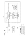
- FIG. 3 is a diagram illustrating functional blocks of the controller 12. As shown in FIG. 3 , the controller 12 includes a detection device 121, a control device (changer device) 122, a communication device 123, and a storage device 124.
- the detection device 121 detects that the plurality of cells 11 are connected to each other. Specifically, the detection device 121 detects that the cells 11 are connected to each other based on information received from connection sensors (not shown) disposed on the outer walls 112c and 112d of the cells 11.
- the connection sensor may be any sensor capable of detecting that the outer walls 112c and 112d of the respective cells 11 different from each other are connected (come into contact) to each other. Examples of the connection sensor include, but are not limited to, a sensor to detect pressure at the time of the contact, a sensor to detect an electrical change caused by the contact, and a sensor to detect a temperature change caused by the contact.
- the connection sensor is able to identify the connected cell 11.
- the cell 11 and the controller 12 are connected to each other through a cable harness (not shown) so as to ensure that information (including information indicating the connected cells 11) indicating connection of the cells 11 is input to the detection device 121 from the connection sensor.
- the cell 11 may be coupled to the controller 12 wirelessly.
- the information indicating connection of the cells 11 detected by the detector 121 is input into the control device 122 and the communication device 123.
- the control device 122 generates an operation command to control the operation of the robot 10. Specifically, the control device 122 is coupled to the actuators of the robot 10 through the cable harness 13, and uses the operation command to drive the actuators, thereby controlling the operation of the robot 10.
- the control device 122 controls the operation of the cell 11 based on the information indicating connection of the cells 11 received from the detection device 121.
- the control device 122 opens one of the outer walls 112c and 112d of the cell 11 that is connected to another cell 11. By opening the connected side wall 112c or 112d of one connected cell 11 (among the connected cells 11), the work area of the one connected cell 11 is available for use by the robot 10 accommodated in the other connected cell 11.
- the work area of the robot 10 is widened.
- the other cell 11 connected to the one cell 11 will be occasionally referred to as a cell 11A; the robot 10 accommodated in the cell 11A will be occasionally referred to as a robot 10A; and the controller 12 accommodated in the cell 11A is occasionally referred to as a controller 12A.
- the communication device 123 Based on the information indicating connection of the cells 11 (including information indicating the connected cell 11A) received from the detection device 121, the communication device 123 communicates with the communication device 123A of the controller 12A, which is accommodated in the connected cell 11A.
- the communication device 123 (controller 12) and the communication device 123A (controller 12A) may communicate with each other wirelessly or through a cable harness (not shown) that couples the controller 12 and the controller 12A to each other. It is possible to provide a programmable logic controller (PLC) (not shown) as an upper device common to the controllers 12 and 12A to centralize the control of input and output signals to and from the controllers 12 and 12A.
- PLC programmable logic controller
- the communication between the communication devices 123 and 123A will be described.
- the communication device 123 reads information related to each job of the robot 10 from the storage device 124.
- the storage device 124 stores one job or a plurality of jobs of the robot 10 determined in accordance with the cell (cell 11A, for example) connected to the cell 11.
- the information related to each job includes work area information and time information.
- the area information and the time information are stored on a single job basis.
- the work area information is information on an area in which the robot 10 works.
- the work area information includes information on an own cell work area, which is the work area within the cell 11 accommodating the robot 10, and information on the other cell work area, which is the work area within the cell 11A connected to the cell 11.
- the time information is information indicating the start time of each job (the time required for the robot 10 to start the job after the other cell 11A has been connected to the cell 11), and the time that each job takes.
- the information on each job of the robot 10 read from the storage device 124 is notified (transmitted) from the communication device 123 to the communication device 123A of the controller 12A accommodated in the connected cell 11A.
- the communication device 123 may notify the communication device 123A of the information on each job of the robot 10 only when the work area information, which is the information on each job of the robot 10, includes information on the other work area as the work area within the cell 11A connected to the cell 11, that is, when the robot 10 is to work in the connected cell 11A.
- the communication device 123 also inputs the information on each job of the robot 10 into the control device 122.
- the communication device 123A Upon receiving the notification from the communication device 123, the communication device 123A reads information on each job of the robot 10A accommodated in the cell 11A from a storage device (not shown). The communication device 123A determines whether the robot 10 and the robot 10A will interfere with each other in the cell 11A based on the received work area information and the received time information of the robot 10 and based on the work area information and the time information of the robot 10A read from the storage device. The communication device 123A notifies the communication device 123 of information on whether an interference will occur and the information on each job of the robot 10A.
- the communication device 123 Upon receiving the notification from the communication device 123A, the communication device 123 inputs the information on whether the interference will occur and the information on each job of the robot 10A into the control device 122.
- the control device 122 serves as a changer device.
- the changer device changes at least one operation command among the operation commands for the robots 10A and 10A respectively accommodated in the plurality of connected cells 11 and 11A.
- the control device 122 changes the at least one operation command for the robot 10A in response to the detection of the connection between the cells 11 and 11A by the detection device 121, based on the information on each job of the robot 10 and the robot 10A and the information on whether the interference will occur received from the communication device 123.
- the control device 122 controls the robot 10 to operate normally. Specifically, the control device 122 controls the robot 10 in accordance with the information on each job of the robot 10.
- the control device 122 changes the operation command for the robot 10 to avoid the interference between the robots 10 and 10A. Specifically, the control device 122 suspends the job of the robot 10 until the job of the robot 10A is complete, so as to avoid the interference between the robots 10 and 10A. Upon elapse of a predetermined period of time, the control device 122 makes a communication resume request to the communication device 123 so as to resume the communication between the above-described communication devices 123 and 123A.
- the control device 122 may switch the order of the interchangeable jobs and control the robot 10 to operate in the switched order.
- the control device 122 may not necessarily give priority to the job of the robot 10A; instead, the control device 122 may prioritize the robots 10 and 10A to determine which job to give priority.
- the control device 122 may set the suspended time (waiting time) of the job of the robot 10 by taking into consideration the complete time of the job of the robot 10A interfering with the robot 10. This eliminates making repetitive communication resume requests to the communication device 123. This, in turn, results in an operation program that eliminates an interference between the robots 10 and 10A while minimizing the number of times of real-time communication.
- the control device 122 may change the operation command for the robot 10 to synchronize the operations of the robots 10 and 10A. Specifically, the control device 122 changes the operation command for the robot 10 to synchronize the operations of the robots 10 and 10A when the control device 122 determines, based on the information on each job of the robots 10 and 10A input from the communication device 123, that controlling the robots 10 and 10A to work synchronously makes their work efficient; for example, when the control device 122 determines that the workpieces W could be more readily conveyed if the robots 10 and 10A operate synchronously.
- FIG. 4 is a front view of the adjacent cells 11 and 11A connected to each other.
- the casters 111a and the stoppers 111b shown in FIG. 2 are not shown in FIG. 4 .
- the cell 11 accommodates the robot 10, the controller 12, and a workpiece W
- the cell 11A accommodates the robot 10A, the controller 12A, a workpiece W, and a tool T.
- the tool T is an additional part mounted to a robot.
- the holding claws 104a mounted to the distal end of the hand 104 are one type of the tool T.
- the cell 11 and the cell 11A are connected to each other with the outer wall 112d of the cell 11 and the outer wall 112c of the cell 11A connected to each other.
- the information indicating that the cells 11 and 11A are connected to each other is detected by the detection device 121 and input into the control device 122 and the communication device 123.
- the control device 122 opens the outer wall 112d of the cell 11 and the outer wall 112c of the cell 11A, as shown in FIG. 4 . This ensures that the robots 10 and 10A share the work areas within the cells 11 and 11A; for example, the robot 10 accommodated in the cell 11 is able to use the tool T accommodated in the cell 11A.
- the control device 122 sets a specific area S in which to control the operations of the robots 10 and 10A respectively accommodated in the connected cells 11 and 11A. Based on the specific area S, the control device 122 changes the operation command to avoid the interference between the robots 10 and 10A.
- the specific area S is an exclusive area E or a cooperative area C.
- the exclusive area E is where a particular robot among the robots 10 and 10A respectively corresponding to the connected cells 11 and 11A is allowed to work.
- the cooperative area C is sharable as a work area among the robots 10 and 10A respectively corresponding to the connected cells 11 and 11A.
- the control device 122 of the cell 11 may set the cell 11A part of the specific area S of the cells 11 and 11A.
- the control device 122 stores in advance the specific area S of each cell connectable to the cell 11 as specific area information. Upon receiving the information indicating connection of the cell 11 (including the information indicating the connected cell 11A) from the detection device 121, the control device 122 sets the specific area S based on the information indicating the connected cell 11A and the specific area information. It is possible to set the specific area S for each job of the robots 10 and 10A.
- the control device 122 changes the operation command for the robot 10. Specifically, when the robot 10 performs an operation of entering the exclusive area E, where only the robot 10A in the cell 11A is allowed to operate, the control device 122 suspends the operation of the robot 10 or controls the robot 10 to withdraw from the exclusive area E, so as to avoid the interference between the robots 10 and 10A.
- the control device 122 may, for example, set a virtual cube in the exclusive area E and determine whether a control point at the distal end of the hand 10 has entered the cube. It is also possible to mount a sensor to each of the robot arms 105 to 110 of the robot 10 and determine that the robot 10 has entered the exclusive area E when any of the sensors enters the exclusive area E.
- FIG. 5 is a plan view of the connected cells 11 and 11A, schematically illustrating the specific area S.
- the same cells 11 and 11A and the same components (such as the robots 10 and 10A) accommodated in the cells 11 and 11A are shown in FIGs. 4 and 5 .
- the specific area S is set across the cells 11 and 11A. Since the robots 10 and 10A need to share the tool T accommodated in the cell 11A, the cooperative area C is set as an area in the specific area S to which the robot 10 has an admission so as to use the tool T.
- An exclusive area E1 for the robot 10 is set as an area where only the robot 10 needs to enter to use the tool T
- an exclusive area E2 for the robot 10A is set as an area where only the robot 10A needs to enter to use the tool T.
- a virtual cube for example, is set in the exclusive area E2, and the control device 122 determines whether a control point at the distal end of the robot 10 has entered the cube. When the control point has entered the cube, the control device 122 changes the operation command for the robot 10 to suspend the operation of the robot 10, or controls the robot 10 to withdraw from the exclusive area E2.
- FIG. 6 is a flowchart of a procedure for the operation change processing for changing the work area of the robot.
- Each operation shown in FIG. 6 is described in association with the cells 11 and 11A and the components (such as the robots 10 and 10A) accommodated in the cells 11 and 11A shown in FIGs. 4 and 5 . It is assumed that workpieces W have been already supplied to each of the cells 11 and 11A respectively accommodating the plurality of robots 10 and 10A to perform work on the workpieces W (supplying step).
- the detection device 121 determines whether another cell is connected to the cell 11 (S101, detecting step), and detects that the cell 11A is connected to the cell 11.
- the controllers 12 and 12A the communication devices 123 and 123A of the connected cells 11 and 11A communicate with each other (step S102).
- the communication device 123 notifies the communication device 123A of information on each job of the robot 10.
- the communication device 123A notifies the communication device 123 of information on whether the robots 10 and 10A will interfere with each other and information on each job of the robot 10A.
- the communication device 123 inputs into the control device 122 the information on whether the robots 10 and 10A will interfere with each other and the information on each job of the robots 10 and 10A.
- the control device 122 changes the operation commands for the robots 10 and 10A respectively accommodated in the connected cells 11 and 11A (S103, changing step). Specifically, when the control device 122 determines that the robots 10 and 10A will interfere with each other, the job of the robot 10 is suspended until the job of the robot 10A is complete, or the order of the jobs of the robot 10 is changed. When the control device 122 sets the specific area S and the robot 10 performs an operation that is against the rule of the specific area S, the operation command for the robot 10 is changed.
- the control device 122 suspends the operation of the robot 10, or controls the robot 10 to withdraw from the exclusive area E.
- the workpieces W are subjected to a predetermined work by the robots 10 and 10A, and after the work, the workpieces W are taken out from the cells 11 and 11A (taking out step).
- the control device 122 changes the operation command for the robot 10 accommodated in the cell 11.
- control device 122 is capable of automatic change of the operation command for the robot 10 in response to the detection device 121's detection of connection between cells 11 and 11A. This facilitates the operation command change processing, and significantly saves the operator the labor of management. Thus, a production line is quickly established. Additionally, saving the operator the labor of management reduces the cost of cell replacement.
- the control device 122 sets the specific area S in which to control the operations of the robots 10 and 10A respectively accommodated in the connected cells 11 and 11A. Based on the specific area S, the control device 122 changes the operation command. Thus, the robots 10 and 10A operate without interfering with each other and are not controlled unnecessarily in an area in which the robots 10 and 10A are able to cooperate. Specifically, the control device 122 sets the specific area S at the exclusive area E, where a particular robot among the robots 10 and 10A is allowed to work, or at the cooperative area C, which is sharable as a work area among the robots 10 and 10A. The control device 122 may change the operation command to synchronize the operations of the robots 10 and 10A. This further improves the efficiency of work effected by the cell connection.
- control device 122 has been described as changing the operation command for the robot 10 in response to the detection of the connection between the cells 11 and 11A by the detection device 121, based on the information on each job of the robot 10 and the robot 10A and based on the information on whether an interference will occur received from the communication device 123.
- the communication device 123 may not necessarily be included in the robot system. The communication device 123 is not required when, for example, the control device 122 stores in advance: each job of the robot 10 and another robot accommodated in a cell connectable to the cell 11; and information on whether the robot 10 and the other robot will interfere with each other.
- the cooperative area C may be disposed along the body of the robot 10.
- the control device 122 may change the operation command by changing the order of commands for operating the robot 10.
- the control device 122 may be disposed in the PLC, which is an upper device. In this case, the PLC may change the operation command for the robot 10.
- the specific area S may be set by taking into consideration an error that is based on the operation of the robot 10, an external environment, and the like.
Landscapes
- Engineering & Computer Science (AREA)
- Robotics (AREA)
- Mechanical Engineering (AREA)
- General Engineering & Computer Science (AREA)
- Manufacturing & Machinery (AREA)
- Quality & Reliability (AREA)
- Physics & Mathematics (AREA)
- General Physics & Mathematics (AREA)
- Automation & Control Theory (AREA)
- Manipulator (AREA)
Abstract
Description
- The present invention relates to a robot system, a method for controlling a robot, and a method for producing a to-be-processed material.
- In the field of manufacture of industrial products, responsiveness to market changes is a recent requirement. A cell production system of high variety/low volume production is known to satisfy such a requirement. For example, Japanese Unexamined Patent Application Publication No.
2009-262310 - The contents of Japanese Unexamined Patent Application Publication No.
2009-262310 - In connecting the cells together, it is necessary to check whether the adjacent robots satisfy safety and efficiency requirements when they operate. This takes a significantly long time before a production line is established. Thus, in this technical field, there is need for a robot system, a method for controlling a robot, and a method for producing a to-be-processed material that ensure quick establishment of a production line that satisfies safety and efficiency requirements.
- According to one aspect of the present disclosure, a robot system 1 includes a plurality of
robots cells detection device 121, and achanger device 122. Each of the plurality ofrobots cells robots detection device 121 is configured to detect that the plurality ofcells detection device 121 detects that the plurality ofcells changer device 122 is configured to change at least one operation command among operation commands for the plurality ofrobots cells - The robot system, the method for controlling a robot, and a method for producing a to-be-processed material according to the present disclosure ensure quick establishment of a production line.
- A more complete appreciation of the present disclosure and many of the attendant advantages thereof will be readily obtained as the same becomes better understood by reference to the following detailed description when considered in connection with the accompanying drawings, wherein:
-
FIG. 1 is a plan view of a robot system according to an embodiment; -
FIG. 2 is a side view of a cell included in the robot system shown inFIG. 1 ; -
FIG. 3 is a diagram illustrating functional blocks of a controller; -
FIG. 4 is a front view of connected cells in which adjacent cells are connected to each other; -
FIG. 5 is a plan view of the connected cells, schematically illustrating a specific area; and -
FIG. 6 is a flowchart of a procedure for operation command change processing associated with changing a work area of a robot. - The embodiments will now be described with reference to the accompanying drawings, wherein like reference numerals designate corresponding or identical elements throughout the various drawings.
- In a robot system according to an embodiment, the robots accommodated the cells perform various kinds of work such as processing and assembly on a workpiece (to-be-worked materials). The workpiece may be a single part, or a product or a semi-processed product formed of a combination of a plurality of parts. The robot system is used for what is called a cell production system. The cells accommodating the robots are densely arranged in the robot system according to this embodiment. This improves the productivity of the workpieces W. The workpiece may be any kind of item subject to work such as conveyance and assembly in the robot system. Examples of the to-be-processed material include, but are not limited to, parts such as bolts, substrate assemblies for electronic use, automobiles, and processed food.
-
FIG. 1 is a plan view of a robot system 1 according to this embodiment. As shown inFIG. 1 , the robot system 1 according to this embodiment includes a plurality ofrobots 10 and a plurality ofcells 11. Therobots 10 perform various kinds of work on a workpiece. Thecells 11 each accommodate corresponding one of therobots 10. Eachcell 11 further accommodates acable harness 13 to couple therobot 10 to acontroller 12 in a mutually communicable manner. Therobot 10 and thecontroller 12 may be coupled to each other wirelessly, or thecontroller 12 may be built in therobot 10. - The
cell 11 includes arectangular mount 111 andouter walls mount 111 serves as a bottom surface to support therobot 10. Theouter walls mount 111. Therobot 10 is accommodated in the area of space defined by themount 111 and theouter walls cells 11 are connectable to each other. Twoadjacent cells 11 are connected to each other with theouter wall 112c of onecell 11 physically connected to theouter wall 112d of theother cell 11. - Next, an internal configuration of the
cell 11 will be described in detail by referring toFIG. 2. FIG. 2 is a side view of a cell included in the robot system shown inFIG. 1 . As shown inFIG. 2 , thecell 11 accommodates a workpiece W as a to-be-worked material, in addition to therobot 10 and thecontroller 12. The workpiece W is placed on a work table 14. Thecontroller 12 is disposed under the work table 14. Theside wall 112a on the front side of thecell 11 is where the following operation parts, not shown, are collectively disposed: an opening through which the workpiece W is supplied and taken out; a monitor on which to check the work status of the robot; and various gauges and switches. This ensures that the operator only needs to be positioned on the front side of thecell 11 when operating the robot system 1. Each of theouter walls 112a to 112d of thecell 11 has a window (not shown) on a part of each outer wall. The window is made of polycarbonate superior in transparency and impact resistance, and thus enables the operator to check the work status through the window. Thecell 11 includes casters 111a and stoppers 111b on the lower surface of themount 111. The casters 111a and the stoppers 111b facilitate the movement and fixation of thecell 11. - The
robot 10 includes abase 102, arobot arm 103, and ahand 104 as an end effector. Thebase 102 is mounted to abase 101 secured on themount 111. Therobot arm 103 extends upward from thebase 102. Thehand 104 is mounted to the distal end of therobot arm 103. Therobot 10 operates based on an operation command from thecontroller 12. The operation command is a command as a program to activate the robot or a combination job of programs to activate the robot. - The
robot arm 103 is made up of first tosixth arms 105 to 110 coupled to each other, in the order from the base end (base 102) side to the distal end (hand 104) side. Each of these arms accommodates an actuator to drive the arm into rotation as indicated by the two-headed arrows shown inFIG. 2 at joints where the arms are coupled to each other. - The
sixth arm 110, which is at the distal end of therobot arm 103, incorporates an actuator to drive thehand 104 into rotation. Thehand 104 incorporates an actuator to drive a pair of holdingclaws 104a mounted to the distal end of thehand 104. - Under the control of the
controller 12, therobot 10 operates the first to thesixth arms 105 to 110, thehand 104, and the holdingclaws 104a to perform work such as processing and assembly on the workpiece W. - An example of the
controller 12 is a computer including an arithmetic operation device, a storage device, and an input-output device. Functions of thecontroller 12 will be described by referring toFIG. 3. FIG. 3 is a diagram illustrating functional blocks of thecontroller 12. As shown inFIG. 3 , thecontroller 12 includes adetection device 121, a control device (changer device) 122, acommunication device 123, and astorage device 124. - The
detection device 121 detects that the plurality ofcells 11 are connected to each other. Specifically, thedetection device 121 detects that thecells 11 are connected to each other based on information received from connection sensors (not shown) disposed on theouter walls cells 11. The connection sensor may be any sensor capable of detecting that theouter walls respective cells 11 different from each other are connected (come into contact) to each other. Examples of the connection sensor include, but are not limited to, a sensor to detect pressure at the time of the contact, a sensor to detect an electrical change caused by the contact, and a sensor to detect a temperature change caused by the contact. The connection sensor is able to identify theconnected cell 11. Thecell 11 and thecontroller 12 are connected to each other through a cable harness (not shown) so as to ensure that information (including information indicating the connected cells 11) indicating connection of thecells 11 is input to thedetection device 121 from the connection sensor. Thecell 11 may be coupled to thecontroller 12 wirelessly. The information indicating connection of thecells 11 detected by thedetector 121 is input into thecontrol device 122 and thecommunication device 123. - The
control device 122 generates an operation command to control the operation of therobot 10. Specifically, thecontrol device 122 is coupled to the actuators of therobot 10 through thecable harness 13, and uses the operation command to drive the actuators, thereby controlling the operation of therobot 10. Thecontrol device 122 controls the operation of thecell 11 based on the information indicating connection of thecells 11 received from thedetection device 121. Upon receiving the information from thedetection device 121, thecontrol device 122 opens one of theouter walls cell 11 that is connected to anothercell 11. By opening theconnected side wall connected cell 11 is available for use by therobot 10 accommodated in the otherconnected cell 11. That is, the work area of therobot 10 is widened. In the following description, theother cell 11 connected to the onecell 11 will be occasionally referred to as acell 11A; therobot 10 accommodated in thecell 11A will be occasionally referred to as arobot 10A; and thecontroller 12 accommodated in thecell 11A is occasionally referred to as acontroller 12A. - Based on the information indicating connection of the cells 11 (including information indicating the
connected cell 11A) received from thedetection device 121, thecommunication device 123 communicates with thecommunication device 123A of thecontroller 12A, which is accommodated in theconnected cell 11A. The communication device 123 (controller 12) and thecommunication device 123A (controller 12A) may communicate with each other wirelessly or through a cable harness (not shown) that couples thecontroller 12 and thecontroller 12A to each other. It is possible to provide a programmable logic controller (PLC) (not shown) as an upper device common to thecontrollers controllers - The communication between the
communication devices detection device 121, thecommunication device 123 reads information related to each job of therobot 10 from thestorage device 124. Thestorage device 124 stores one job or a plurality of jobs of therobot 10 determined in accordance with the cell (cell 11A, for example) connected to thecell 11. The information related to each job includes work area information and time information. The area information and the time information are stored on a single job basis. The work area information is information on an area in which therobot 10 works. The work area information includes information on an own cell work area, which is the work area within thecell 11 accommodating therobot 10, and information on the other cell work area, which is the work area within thecell 11A connected to thecell 11. The time information is information indicating the start time of each job (the time required for therobot 10 to start the job after theother cell 11A has been connected to the cell 11), and the time that each job takes. - The information on each job of the
robot 10 read from thestorage device 124 is notified (transmitted) from thecommunication device 123 to thecommunication device 123A of thecontroller 12A accommodated in theconnected cell 11A. Thecommunication device 123 may notify thecommunication device 123A of the information on each job of therobot 10 only when the work area information, which is the information on each job of therobot 10, includes information on the other work area as the work area within thecell 11A connected to thecell 11, that is, when therobot 10 is to work in theconnected cell 11A. Thecommunication device 123 also inputs the information on each job of therobot 10 into thecontrol device 122. - Upon receiving the notification from the
communication device 123, thecommunication device 123A reads information on each job of therobot 10A accommodated in thecell 11A from a storage device (not shown). Thecommunication device 123A determines whether therobot 10 and therobot 10A will interfere with each other in thecell 11A based on the received work area information and the received time information of therobot 10 and based on the work area information and the time information of therobot 10A read from the storage device. Thecommunication device 123A notifies thecommunication device 123 of information on whether an interference will occur and the information on each job of therobot 10A. - Upon receiving the notification from the
communication device 123A, thecommunication device 123 inputs the information on whether the interference will occur and the information on each job of therobot 10A into thecontrol device 122. - The
control device 122 serves as a changer device. When thedetection device 121 detects that thecells robots connected cells control device 122 changes the at least one operation command for therobot 10A in response to the detection of the connection between thecells detection device 121, based on the information on each job of therobot 10 and therobot 10A and the information on whether the interference will occur received from thecommunication device 123. When therobots cell 11A, thecontrol device 122 controls therobot 10 to operate normally. Specifically, thecontrol device 122 controls therobot 10 in accordance with the information on each job of therobot 10. - When the
robots cell 11A if therobot 10 operates normally, thecontrol device 122 changes the operation command for therobot 10 to avoid the interference between therobots control device 122 suspends the job of therobot 10 until the job of therobot 10A is complete, so as to avoid the interference between therobots control device 122 makes a communication resume request to thecommunication device 123 so as to resume the communication between the above-describedcommunication devices - When it is possible to avoid the interference between the
robots control device 122 may switch the order of the interchangeable jobs and control therobot 10 to operate in the switched order. Thecontrol device 122 may not necessarily give priority to the job of therobot 10A; instead, thecontrol device 122 may prioritize therobots control device 122 may set the suspended time (waiting time) of the job of therobot 10 by taking into consideration the complete time of the job of therobot 10A interfering with therobot 10. This eliminates making repetitive communication resume requests to thecommunication device 123. This, in turn, results in an operation program that eliminates an interference between therobots - When the
cells control device 122 may change the operation command for therobot 10 to synchronize the operations of therobots control device 122 changes the operation command for therobot 10 to synchronize the operations of therobots control device 122 determines, based on the information on each job of therobots communication device 123, that controlling therobots control device 122 determines that the workpieces W could be more readily conveyed if therobots - An image of the
connected cells FIG. 4. FIG. 4 is a front view of theadjacent cells FIG. 2 are not shown inFIG. 4 . As shown inFIG. 4 , thecell 11 accommodates therobot 10, thecontroller 12, and a workpiece W, while thecell 11A accommodates therobot 10A, thecontroller 12A, a workpiece W, and a tool T. The tool T is an additional part mounted to a robot. For example, the holdingclaws 104a mounted to the distal end of thehand 104 are one type of the tool T. Thecell 11 and thecell 11A are connected to each other with theouter wall 112d of thecell 11 and theouter wall 112c of thecell 11A connected to each other. - As described above, the information indicating that the
cells detection device 121 and input into thecontrol device 122 and thecommunication device 123. Thecontrol device 122 opens theouter wall 112d of thecell 11 and theouter wall 112c of thecell 11A, as shown inFIG. 4 . This ensures that therobots cells robot 10 accommodated in thecell 11 is able to use the tool T accommodated in thecell 11A. - The
control device 122 sets a specific area S in which to control the operations of therobots connected cells control device 122 changes the operation command to avoid the interference between therobots robots connected cells robots connected cells control device 122 of thecell 11 may set thecell 11A part of the specific area S of thecells control device 122 stores in advance the specific area S of each cell connectable to thecell 11 as specific area information. Upon receiving the information indicating connection of the cell 11 (including the information indicating theconnected cell 11A) from thedetection device 121, thecontrol device 122 sets the specific area S based on the information indicating theconnected cell 11A and the specific area information. It is possible to set the specific area S for each job of therobots - When the
robot 10 in thecell 11 performs an operation that is against a rule of the specific area S after thecontrol device 122 has set the specific area S, thecontrol device 122 changes the operation command for therobot 10. Specifically, when therobot 10 performs an operation of entering the exclusive area E, where only therobot 10A in thecell 11A is allowed to operate, thecontrol device 122 suspends the operation of therobot 10 or controls therobot 10 to withdraw from the exclusive area E, so as to avoid the interference between therobots - To determine whether the
robot 10 has entered the exclusive area E, thecontrol device 122 may, for example, set a virtual cube in the exclusive area E and determine whether a control point at the distal end of thehand 10 has entered the cube. It is also possible to mount a sensor to each of therobot arms 105 to 110 of therobot 10 and determine that therobot 10 has entered the exclusive area E when any of the sensors enters the exclusive area E. - An image of how to set the specific area will be described by referring to
FIG. 5. FIG. 5 is a plan view of theconnected cells same cells robots cells FIGs. 4 and5 . As shown inFIG. 5 , the specific area S is set across thecells robots cell 11A, the cooperative area C is set as an area in the specific area S to which therobot 10 has an admission so as to use the tool T. An exclusive area E1 for therobot 10 is set as an area where only therobot 10 needs to enter to use the tool T, and an exclusive area E2 for therobot 10A is set as an area where only therobot 10A needs to enter to use the tool T. A virtual cube, for example, is set in the exclusive area E2, and thecontrol device 122 determines whether a control point at the distal end of therobot 10 has entered the cube. When the control point has entered the cube, thecontrol device 122 changes the operation command for therobot 10 to suspend the operation of therobot 10, or controls therobot 10 to withdraw from the exclusive area E2. - Next, the operation change processing at the time of cell connection will be described by referring to
FIG. 6. FIG. 6 is a flowchart of a procedure for the operation change processing for changing the work area of the robot. Each operation shown inFIG. 6 is described in association with thecells robots cells FIGs. 4 and5 . It is assumed that workpieces W have been already supplied to each of thecells robots - First, the
detection device 121 determines whether another cell is connected to the cell 11 (S101, detecting step), and detects that thecell 11A is connected to thecell 11. When at step S101 thedetection device 121 determines that no cell is connected to thecell 11, the processing ends. Then, thecontrollers communication devices connected cells communication device 123 notifies thecommunication device 123A of information on each job of therobot 10. Thecommunication device 123A notifies thecommunication device 123 of information on whether therobots robot 10A. Thecommunication device 123 inputs into thecontrol device 122 the information on whether therobots robots - Then, the
control device 122 changes the operation commands for therobots connected cells control device 122 determines that therobots robot 10 is suspended until the job of therobot 10A is complete, or the order of the jobs of therobot 10 is changed. When thecontrol device 122 sets the specific area S and therobot 10 performs an operation that is against the rule of the specific area S, the operation command for therobot 10 is changed. Specifically, when therobot 10 performs an operation of entering the exclusive area E, where only therobot 10A in thecell 11A is allowed to work, thecontrol device 122 suspends the operation of therobot 10, or controls therobot 10 to withdraw from the exclusive area E. After the operation command for therobot 10 has been changed, the workpieces W are subjected to a predetermined work by therobots cells - As has been described hereinbefore, in the robot system 1 according to this embodiment, when the
detection device 121 detects that the plurality ofcells control device 122 changes the operation command for therobot 10 accommodated in thecell 11. - When a plurality of cells accommodating robots are connected to each other so that the robots share their work areas (cells) and thus work efficiently, it is necessary to change an operation command for at least one of the robots so as to avoid an interference between the robots. Conventionally, the operation command has been changed by an operator by performing the operation command change processing with respect to an upper device (PLC for example) common to a plurality of controllers, so as to avoid an interference between the robots. Performing the operation command change processing with respect to the upper device is significantly laborious for the operator.
- In the robot system 1 according to this embodiment, the
control device 122 is capable of automatic change of the operation command for therobot 10 in response to thedetection device 121's detection of connection betweencells - The
control device 122 sets the specific area S in which to control the operations of therobots connected cells control device 122 changes the operation command. Thus, therobots robots control device 122 sets the specific area S at the exclusive area E, where a particular robot among therobots robots control device 122 may change the operation command to synchronize the operations of therobots - Obviously, numerous modifications and variations of the present disclosure are possible in light of the above teachings. It is therefore to be understood that within the scope of the appended claims, the present disclosure may be practiced otherwise than as specifically described herein. For example, the
control device 122 has been described as changing the operation command for therobot 10 in response to the detection of the connection between thecells detection device 121, based on the information on each job of therobot 10 and therobot 10A and based on the information on whether an interference will occur received from thecommunication device 123. Thecommunication device 123, however, may not necessarily be included in the robot system. Thecommunication device 123 is not required when, for example, thecontrol device 122 stores in advance: each job of therobot 10 and another robot accommodated in a cell connectable to thecell 11; and information on whether therobot 10 and the other robot will interfere with each other. - In order to prevent the
robot 10 from entering the exclusive area E, it is possible to provide a sensor along the exclusive area E to monitor the operation of therobot 10. The cooperative area C may be disposed along the body of therobot 10. Thecontrol device 122 may change the operation command by changing the order of commands for operating therobot 10. Thecontrol device 122 may be disposed in the PLC, which is an upper device. In this case, the PLC may change the operation command for therobot 10. The specific area S may be set by taking into consideration an error that is based on the operation of therobot 10, an external environment, and the like. - 1 Robot system
- 10, 10A Robot
- 11, 11A Cell
- 121 Detection device
- 122 Control device (changer device)
- C Cooperative area
- E, E1, E2 Exclusive area
- S Specific area
- W Workpiece (to-be-processed material)
Claims (6)
- A robot system 1, characterized by:a plurality of robots 10, 10A each configured to operate based on an operation command;a plurality of cells 11, 11A respectively accommodating the plurality of robots 10, 10A and being connectable to each other;a detection device 121 configured to detect that the plurality of cells 11, 11A are connected to each other; anda changer device 122 configured to, when the detection device 121 detects that the plurality of cells 11, 11A are connected to each other, change at least one operation command among operation commands for the plurality of robots 10, 10A respectively accommodated in the connected cells 11, 11A.
- The robot system 1 according to claim 1, wherein the changer device 122 is configured to change the at least one operation command based on a specific area in which to control operations of the plurality of robots 10, 10A respectively accommodated in the connected cells 11, 11A.
- The robot system 1 according to claim 2, wherein the specific area comprises one area among an exclusive area and a cooperative area, the exclusive area being where one particular robot among the plurality of robots 10, 10A is allowed to operate, the cooperative area being sharable as a work area among the plurality of robots 10, 10A.
- The robot system 1 according to any one of claims 1 to 3, wherein the changer device 122 is configured to change the at least one operation command to synchronize the operations of the plurality of robots 10, 10A.
- A method for controlling a robot 10, 10A, characterized by:detecting connection between a plurality of cells 11, 11A respectively corresponding to a plurality of robots 10, 10A each configured to operate based on an operation command; andwhen the connection between the plurality of cells 11, 11A is detected, changing at least one operation command among operation commands for the plurality of robots 10, 10A respectively accommodated in the connected cells 11, 11A.
- A method for producing a to-be-processed material, characterized by:supplying to-be-processed materials each to a corresponding one cell among a plurality of cells 11, 11A respectively corresponding to a plurality of robots 10, 10A each configured to operate based on an operation command;detecting connection between the plurality of cells 11, 11A;when the connection between the plurality of cells 11, 11A is detected in the detecting step, changing at least one operation command among operation commands for the plurality of robots 10, 10A respectively accommodated in the connected cells 11, 11A; andtaking out the to-be-processed materials done with work performed by the plurality of robots 10, 10A from the cells 11, 11A accommodating the to-be-processed materials.
Applications Claiming Priority (1)
| Application Number | Priority Date | Filing Date | Title |
|---|---|---|---|
| JP2013053305A JP5768829B2 (en) | 2013-03-15 | 2013-03-15 | Robot system, robot control method, and workpiece manufacturing method |
Publications (2)
| Publication Number | Publication Date |
|---|---|
| EP2783808A2 true EP2783808A2 (en) | 2014-10-01 |
| EP2783808A3 EP2783808A3 (en) | 2015-07-22 |
Family
ID=50190335
Family Applications (1)
| Application Number | Title | Priority Date | Filing Date |
|---|---|---|---|
| EP14157609.0A Withdrawn EP2783808A3 (en) | 2013-03-15 | 2014-03-04 | Robot system, method for controlling robot, and method for producing to-be-processed material |
Country Status (4)
| Country | Link |
|---|---|
| US (1) | US9329593B2 (en) |
| EP (1) | EP2783808A3 (en) |
| JP (1) | JP5768829B2 (en) |
| CN (1) | CN104044148A (en) |
Cited By (1)
| Publication number | Priority date | Publication date | Assignee | Title |
|---|---|---|---|---|
| AT527674B1 (en) * | 2023-11-06 | 2025-05-15 | Trumpf Maschinen Austria Gmbh & Co Kg | Positionable robot cell and manufacturing facility with such a robot cell |
Families Citing this family (21)
| Publication number | Priority date | Publication date | Assignee | Title |
|---|---|---|---|---|
| DE112013003209B4 (en) * | 2012-06-29 | 2019-02-07 | Mitsubishi Electric Corporation | Robot control device and robot control method |
| DE102013220798A1 (en) * | 2013-10-15 | 2015-04-16 | Kuka Laboratories Gmbh | Method for handling objects by means of at least two industrial robots, and associated industrial robots |
| US9841749B2 (en) * | 2014-04-01 | 2017-12-12 | Bot & Dolly, Llc | Runtime controller for robotic manufacturing system |
| DE112015003667T5 (en) * | 2014-08-08 | 2017-04-27 | Sony Corporation | transfer device |
| JP2016190298A (en) * | 2015-03-31 | 2016-11-10 | セイコーエプソン株式会社 | Robot and robot system |
| US9707681B2 (en) * | 2015-07-27 | 2017-07-18 | Siemens Industry Software Ltd. | Anti-collision management of overlapping robotic movements |
| US9718188B2 (en) * | 2015-09-21 | 2017-08-01 | Amazon Technologies, Inc. | Networked robotic manipulators |
| JP6249583B2 (en) * | 2015-09-28 | 2017-12-20 | アイダエンジニアリング株式会社 | Operation control device and operation control method for press line |
| JP6360105B2 (en) * | 2016-06-13 | 2018-07-18 | ファナック株式会社 | Robot system |
| CN106227166A (en) * | 2016-08-11 | 2016-12-14 | 贵州翰凯斯智能技术有限公司 | A kind of industrial real-time operation control system based on virtual reality |
| WO2018092222A1 (en) * | 2016-11-16 | 2018-05-24 | 株式会社牧野フライス製作所 | Machine tool system |
| JP6484213B2 (en) * | 2016-12-09 | 2019-03-13 | ファナック株式会社 | Robot system including a plurality of robots, robot control apparatus, and robot control method |
| DK3335844T3 (en) * | 2016-12-15 | 2020-01-06 | Pharma Integration S R L | CONSTRUCTIVE STRUCTURE OF AN INCLUSION DETERMINED FOR AUTOMATED PRODUCTION OF PHARMACEUTICAL OR BIOTECHNICAL ARTICLES |
| JP6514252B2 (en) * | 2017-03-02 | 2019-05-15 | ファナック株式会社 | Robot data setting system, data setting method and program |
| JP7095262B2 (en) * | 2017-11-10 | 2022-07-05 | 株式会社安川電機 | Programming support device, robot system and program generation method |
| TWI660275B (en) * | 2018-06-27 | 2019-05-21 | 廣達電腦股份有限公司 | Methods and systems of distributing task areas for cleaning devices, and cleaning devices |
| TWI687191B (en) * | 2018-10-23 | 2020-03-11 | 廣達電腦股份有限公司 | Methods and systems of distributing task areas for a plurality of cleaning devices |
| CN109343498A (en) * | 2018-11-26 | 2019-02-15 | 清华大学 | Safety evasion system for multiple CNC work units |
| CN111283677B (en) * | 2018-12-10 | 2021-07-06 | 北京猎户星空科技有限公司 | Robot control method and device, robot and robot master controller |
| JP2021094677A (en) * | 2019-12-19 | 2021-06-24 | 本田技研工業株式会社 | Robot control device, robot control method, program and learning model |
| WO2025244947A1 (en) * | 2024-05-24 | 2025-11-27 | Armstrong Robotics, Inc. | System and method for a commercial dishwashing robot |
Citations (1)
| Publication number | Priority date | Publication date | Assignee | Title |
|---|---|---|---|---|
| JP2009262310A (en) | 2008-04-28 | 2009-11-12 | Olympus Corp | Production device and production system |
Family Cites Families (16)
| Publication number | Priority date | Publication date | Assignee | Title |
|---|---|---|---|---|
| JPH04310384A (en) | 1991-04-09 | 1992-11-02 | Toyota Motor Corp | Double-arm robot |
| JP2880590B2 (en) | 1991-07-24 | 1999-04-12 | 株式会社不二越 | Synchronous control method for industrial robot |
| JP2895672B2 (en) * | 1992-01-28 | 1999-05-24 | ファナック株式会社 | Multiple robot control method |
| JP3559306B2 (en) * | 1994-04-15 | 2004-09-02 | ファナック株式会社 | Traveling robot device and method of performing assembly work using the device |
| JPH08202408A (en) * | 1995-01-26 | 1996-08-09 | Komatsu Ltd | Robot line controller |
| JP2756482B2 (en) * | 1995-05-31 | 1998-05-25 | 川崎重工業株式会社 | Robot Placement Method and Structure in Automotive Painting Line |
| JP4207288B2 (en) * | 1998-04-20 | 2009-01-14 | 株式会社デンソー | Assembly processing equipment |
| EP1090722B1 (en) * | 1999-09-16 | 2007-07-25 | Fanuc Ltd | Control system for synchronously cooperative operation of a plurality of robots |
| JP3577028B2 (en) * | 2001-11-07 | 2004-10-13 | 川崎重工業株式会社 | Robot cooperative control system |
| JP2006528082A (en) | 2003-07-18 | 2006-12-14 | ファナック ロボティクス アメリカ,インコーポレイティド | Handling heavy and large workpieces using a gantry robot with two robot arms |
| SE0400091D0 (en) * | 2004-01-16 | 2004-01-16 | Abb Ab | Control system, method and computer program |
| JP2005262369A (en) * | 2004-03-18 | 2005-09-29 | Yaskawa Electric Corp | Robot system |
| JP4159577B2 (en) * | 2005-12-13 | 2008-10-01 | ファナック株式会社 | Interlock automatic setting device and automatic setting method between a plurality of robots |
| JP5653166B2 (en) * | 2010-10-22 | 2015-01-14 | キヤノン株式会社 | Robot cell |
| DE102012103830B4 (en) * | 2011-05-05 | 2022-05-25 | Fanuc Robotics America Corp. | Method and computer-readable media for automatic connection of deadlocks in multiple robot systems |
| JP5751945B2 (en) * | 2011-06-15 | 2015-07-22 | 富士機械製造株式会社 | Multi-robot system and electronic component mounting machine |
-
2013
- 2013-03-15 JP JP2013053305A patent/JP5768829B2/en not_active Expired - Fee Related
-
2014
- 2014-01-28 CN CN201410042310.XA patent/CN104044148A/en active Pending
- 2014-02-27 US US14/191,432 patent/US9329593B2/en not_active Expired - Fee Related
- 2014-03-04 EP EP14157609.0A patent/EP2783808A3/en not_active Withdrawn
Patent Citations (1)
| Publication number | Priority date | Publication date | Assignee | Title |
|---|---|---|---|---|
| JP2009262310A (en) | 2008-04-28 | 2009-11-12 | Olympus Corp | Production device and production system |
Cited By (2)
| Publication number | Priority date | Publication date | Assignee | Title |
|---|---|---|---|---|
| AT527674B1 (en) * | 2023-11-06 | 2025-05-15 | Trumpf Maschinen Austria Gmbh & Co Kg | Positionable robot cell and manufacturing facility with such a robot cell |
| AT527674A4 (en) * | 2023-11-06 | 2025-05-15 | Trumpf Maschinen Austria Gmbh & Co Kg | Positionable robot cell and manufacturing facility with such a robot cell |
Also Published As
| Publication number | Publication date |
|---|---|
| EP2783808A3 (en) | 2015-07-22 |
| US20140277714A1 (en) | 2014-09-18 |
| US9329593B2 (en) | 2016-05-03 |
| CN104044148A (en) | 2014-09-17 |
| JP2014176939A (en) | 2014-09-25 |
| JP5768829B2 (en) | 2015-08-26 |
Similar Documents
| Publication | Publication Date | Title |
|---|---|---|
| US9329593B2 (en) | Robot system, method for controlling robot, and method for producing to-be-processed material | |
| CN107921636B (en) | Robot system | |
| EP2925494B1 (en) | Teleoperation of machines having at least one actuated mechanism and one machine controller comprising a program code including instructions for transferring control of the machine from said controller to a remote control station | |
| US9158299B2 (en) | Robot system and method for producing to-be-worked material | |
| JP5850003B2 (en) | Robot system, robot management computer for robot system, and robot system management method | |
| JP5741616B2 (en) | Production system and product production method | |
| JP5942938B2 (en) | Robot system | |
| EP2783807A2 (en) | Robot system, calibration method, and method for producing to-be-processed material | |
| RU2670553C1 (en) | Production module for implementation of production function | |
| WO2007104662A1 (en) | A robot controller, a computer unit and a base module for a robot controller | |
| JP5954274B2 (en) | Robot system | |
| US12053888B2 (en) | Suspended robot recovery | |
| JP5924190B2 (en) | Production system, robot, control device, production method, and control program | |
| JP2005190437A (en) | Control device management system | |
| US10678231B2 (en) | Production controller equipped with function of identifying cause upon operation stop of production facility including manufacturing facilities | |
| CN109664294A (en) | The method of robot and the device for controlling the first robot and at least one the second robot | |
| JP6414317B2 (en) | Industrial machinery systems | |
| EP3722053B1 (en) | CONTROL DEVICE, WORKPIECE OPERATING DEVICE, WORKPIECE OPERATING SYSTEM AND CONTROL METHOD | |
| CN115427197B (en) | Industrial Robot Systems | |
| CN106826915A (en) | A kind of tactile sensing device of robot's control method and its device | |
| US8473100B2 (en) | System and method for dynamically switching conveyors for robots | |
| US20190033834A1 (en) | Slave device, industrial network system, and method of controlling slave device | |
| US12242253B2 (en) | Multifunctional gateway unit, production system and method for operating a production system | |
| CN110568810B (en) | Control device, control system, and computer-readable medium | |
| JPH0797060A (en) | Palletizing device |
Legal Events
| Date | Code | Title | Description |
|---|---|---|---|
| 17P | Request for examination filed |
Effective date: 20140304 |
|
| AK | Designated contracting states |
Kind code of ref document: A2 Designated state(s): AL AT BE BG CH CY CZ DE DK EE ES FI FR GB GR HR HU IE IS IT LI LT LU LV MC MK MT NL NO PL PT RO RS SE SI SK SM TR |
|
| AX | Request for extension of the european patent |
Extension state: BA ME |
|
| PUAI | Public reference made under article 153(3) epc to a published international application that has entered the european phase |
Free format text: ORIGINAL CODE: 0009012 |
|
| PUAL | Search report despatched |
Free format text: ORIGINAL CODE: 0009013 |
|
| AK | Designated contracting states |
Kind code of ref document: A3 Designated state(s): AL AT BE BG CH CY CZ DE DK EE ES FI FR GB GR HR HU IE IS IT LI LT LU LV MC MK MT NL NO PL PT RO RS SE SI SK SM TR |
|
| AX | Request for extension of the european patent |
Extension state: BA ME |
|
| RIC1 | Information provided on ipc code assigned before grant |
Ipc: B25J 9/16 20060101AFI20150618BHEP |
|
| R17P | Request for examination filed (corrected) |
Effective date: 20150824 |
|
| RBV | Designated contracting states (corrected) |
Designated state(s): AL AT BE BG CH CY CZ DE DK EE ES FI FR GB GR HR HU IE IS IT LI LT LU LV MC MK MT NL NO PL PT RO RS SE SI SK SM TR |
|
| STAA | Information on the status of an ep patent application or granted ep patent |
Free format text: STATUS: THE APPLICATION IS DEEMED TO BE WITHDRAWN |
|
| 18D | Application deemed to be withdrawn |
Effective date: 20161001 |