EP2783803A2 - Robot system and method for producing to-be-processed material - Google Patents
Robot system and method for producing to-be-processed material Download PDFInfo
- Publication number
- EP2783803A2 EP2783803A2 EP20140157432 EP14157432A EP2783803A2 EP 2783803 A2 EP2783803 A2 EP 2783803A2 EP 20140157432 EP20140157432 EP 20140157432 EP 14157432 A EP14157432 A EP 14157432A EP 2783803 A2 EP2783803 A2 EP 2783803A2
- Authority
- EP
- European Patent Office
- Prior art keywords
- robot
- processed material
- robot system
- illumination
- control
- Prior art date
- Legal status (The legal status is an assumption and is not a legal conclusion. Google has not performed a legal analysis and makes no representation as to the accuracy of the status listed.)
- Withdrawn
Links
Images


Classifications
-
- B—PERFORMING OPERATIONS; TRANSPORTING
- B25—HAND TOOLS; PORTABLE POWER-DRIVEN TOOLS; MANIPULATORS
- B25J—MANIPULATORS; CHAMBERS PROVIDED WITH MANIPULATION DEVICES
- B25J9/00—Program-controlled manipulators
- B25J9/16—Program controls
- B25J9/1694—Program controls characterised by use of sensors other than normal servo-feedback from position, speed or acceleration sensors, perception control, multi-sensor controlled systems, sensor fusion
- B25J9/1697—Vision controlled systems
-
- H—ELECTRICITY
- H05—ELECTRIC TECHNIQUES NOT OTHERWISE PROVIDED FOR
- H05B—ELECTRIC HEATING; ELECTRIC LIGHT SOURCES NOT OTHERWISE PROVIDED FOR; CIRCUIT ARRANGEMENTS FOR ELECTRIC LIGHT SOURCES, IN GENERAL
- H05B45/00—Circuit arrangements for operating light-emitting diodes [LED]
- H05B45/10—Controlling the intensity of the light
- H05B45/12—Controlling the intensity of the light using optical feedback
-
- G—PHYSICS
- G05—CONTROLLING; REGULATING
- G05B—CONTROL OR REGULATING SYSTEMS IN GENERAL; FUNCTIONAL ELEMENTS OF SUCH SYSTEMS; MONITORING OR TESTING ARRANGEMENTS FOR SUCH SYSTEMS OR ELEMENTS
- G05B2219/00—Program-control systems
- G05B2219/30—Nc systems
- G05B2219/37—Measurements
- G05B2219/37009—Calibration of vision system, camera, adapt light level
-
- G—PHYSICS
- G05—CONTROLLING; REGULATING
- G05B—CONTROL OR REGULATING SYSTEMS IN GENERAL; FUNCTIONAL ELEMENTS OF SUCH SYSTEMS; MONITORING OR TESTING ARRANGEMENTS FOR SUCH SYSTEMS OR ELEMENTS
- G05B2219/00—Program-control systems
- G05B2219/30—Nc systems
- G05B2219/37—Measurements
- G05B2219/37151—Handling encoder signal, compensation for light variation, stray light
-
- Y—GENERAL TAGGING OF NEW TECHNOLOGICAL DEVELOPMENTS; GENERAL TAGGING OF CROSS-SECTIONAL TECHNOLOGIES SPANNING OVER SEVERAL SECTIONS OF THE IPC; TECHNICAL SUBJECTS COVERED BY FORMER USPC CROSS-REFERENCE ART COLLECTIONS [XRACs] AND DIGESTS
- Y10—TECHNICAL SUBJECTS COVERED BY FORMER USPC
- Y10S—TECHNICAL SUBJECTS COVERED BY FORMER USPC CROSS-REFERENCE ART COLLECTIONS [XRACs] AND DIGESTS
- Y10S901/00—Robots
- Y10S901/46—Sensing device
- Y10S901/47—Optical
Definitions
- the present invention relates to a robot system and a method for producing a to-be-processed material.
- Japanese Unexamined Patent Application Publication No. 2010-188459 and Japanese Unexamined Patent Application Publication No. 2012-011501 each disclose a robot system in which for a robot to hold a to-be-processed material (that is, a workpiece), a camera captures an image of the to-be-processed material to recognize a position and a posture of the to-be-processed material.
- Robot systems are installed in factories and other institutions that contain various light sources including natural light.
- a flash device may be used in some cases together with the camera when it captures an image of the to-be-processed material.
- the camera may receive an amount of light that exceeds the dynamic range of the camera, resulting in an overexposure.
- the overexposure causes an area marked out by white to occur on the captured image. This can inhibit accurate recognition of the to-be-processed material.
- a robot system 1, 2 includes robot 10A, 10B, an image capture device 18A, 18B, a plurality of illumination devices 20A, 20B, and a control device 26A, 26B.
- the at least one robot 10A, 10B is configured to perform a predetermined work on a to-be-processed material.
- the image capture device 18A, 18B is configured to capture an image of the to-be-processed material and has a dynamic range.
- the plurality of illumination devices 20A, 20B are configured to illuminate the to-be-processed material.
- the control device 26A, 26B is configured to control at least one illumination device 20A, 20B among the plurality of illumination devices 20A, 20B to keep an amount of light received by the image capture device 18A, 18B within the dynamic range of the image capture device 18A, 18B.
- the present invention provides a robot system and a method for producing a to-be-processed material that ensure more accurate recognition of the position and posture of a to-be-processed material.
- robots 10A and 10B are respectively accommodated in cells 100A and 100B to perform various kinds of work such as processing and assembly on workpieces W (to-be-worked materials).
- a robot system 1 is also referred to as a cell production system.
- the workpiece W may be any kind of item subject to work such as conveyance and assembly in the robot system 1.
- the to-be-worked material may be the workpiece W itself, or a product or a semi-processed product made of the workpiece W.
- the to-be-worked material may also be a product or a semi-processed product formed of a combination of a plurality of parts.
- the cells 100A and 100B, which respectively accommodate the robots 10A and 10B, are densely arranged in the robot system 1 of this embodiment. This improves the productivity of the workpieces W.
- the robot system 1 includes the two cells 100A and 100B, a programmable logic controller (PLC) 200, and a personal computer (PC) 300. While in this embodiment the robot system 1 includes the two cells 100A and 100B adjacent to each other, the robot system 1 may include more than two cells.
- the cells 100A and 100B have approximately the same configurations. Thus, the following description will be regarding the configuration of the cell 100A will be described, with description of the cell 100B omitted.
- the cell 100A includes the robot 10A and a casing 110A.
- the robot 10A performs various kinds of work on the workpiece W.
- the casing 110A accommodates the robot 10A.
- the casing 110A includes a bottom wall 112A, side walls 114A, and a top wall 116A.
- the bottom wall 112A has a rectangular shape and supports the robot 10A.
- the side walls 114A are upright on the respective sides of the bottom wall 112A.
- the top wall 116A is disposed on the upper ends of the side walls 114A.
- the robot 10A is accommodated in an accommodation space defined by the bottom wall 112A, the side walls 114A, and the top wall 116A.
- casters 118A and stoppers 120A are disposed on the lower surface of the bottom wall 112A.
- the casters 118A make the cell 100A movable, and the stoppers 120A fix the cell 100A.
- One side wall 114A among the side walls 114A that is in contact with the casing 110B of the cell 100B has a communication hole HA.
- the communication hole HA communicates with a communication hole HB, which is formed on a side wall 114B.
- the communication holes HA and HB are each provided with a door (not shown) that is openable and closable. When the cells 100A and 100B are not connected to each other, the doors close the communication holes HA and HB.
- the side wall 114A on the front side of the cell 100A is where the following operation parts, not shown, are collectively disposed: an opening through which the workpiece W is supplied and taken out; a monitor on which to check the work status of the robot; and various gauges and switches. This ensures that the operator only needs to be positioned on the front side of the cell 11 when operating the robot system 1.
- the side walls 114A and the top wall 116A each may have a window (not shown) on at least a part of side walls 114A and the top wall 116A.
- the window is made of a material (such as polycarbonate) superior in transparency and impact resistance, and thus enables the operator to check the work status of the robot 10A in the casing 110A through the window.
- the cell 100A incorporates a work table 12A, a tool box 14A, a robot controller (RC) 16A, a camera 18A, an illumination device 20A, and a sensor 22A.
- the workpiece W is to be placed on the work table 12A.
- the robot 10A performs work on the workpiece W.
- the tool box 14A is disposed on the work table 12A and accommodates tools (end effectors) used by the robot 10A to perform work on the workpiece W.
- the tools include a hand, a driver, a rivet, a drill, and a portable camera.
- the robot controller 16A is coupled to the robot 10A, the camera 18A, the illumination device 20A, the sensor 22A, and the PLC 200, so as to transmit and receive information to and from these elements.
- the robot controller 16A is disposed on the lower surface of the work table 12A and is coupled to the robot 10A through a cable harness 24A.
- the robot 10A and the robot controller 16A may be coupled to each other wirelessly, or the robot 10A may incorporate the robot controller 16A.
- the camera 18A is disposed on the top wall 116A, and mainly captures an image of the work table 12A from above.
- the illumination device 20A is disposed on the top wall 116A.
- the illumination device 20A may be any of various types of light sources. Examples include, but are not limited to, a flash that emits a flash of light, a light bulb, a fluorescent light, and an LED that continuously emit a predetermined amount of light.
- the sensor 22A is disposed adjacent to the camera 18A on the top wall 116A. The sensor 22A detects the intensity (for example, luminosity, brightness, and luminance) of the light received by the camera 18A.
- the robot 10A is also referred to as a manipulator.
- the robot 10A is disposed on the bottom wall 112A of the casing 110A with a base 122A interposed between the robot 10A and the bottom wall 112A, and disposed by a side of the work table 12A.
- the robot 10A operates based on an operation command output from the robot controller 16A.
- the operation command is a command as a program to activate the robot or a combination job of programs to activate the robot.
- the robot 10A includes first to sixth arms 10A 1 to 10A 6 .
- the first arm 10A 1 is coupled to the base 122A.
- the first to sixth arms 10A 1 to 10A 6 are coupled in series in this order from the based end side (the base 122A).
- a coupling portion between the base 122A and the first arm 10A 1 , and coupling portions between the adjacent arms 10A 1 to 10A 6 function as joints of the robot 10A.
- the robot 10A includes a plurality of actuators corresponding to the respective joints.
- the actuators bring the respective arms 10A 1 to 10A 6 into swing movement about the respective joints (see the arrows shown in FIG. 1 ).
- the end effector EA may be a hand removably mounted to the sixth arm 10A 6 , which is at the distal end of the robot 10A.
- the end effector EA is driven by the actuator incorporated in the sixth arm 10A 6 .
- the end effector EA is a hand as shown in FIG. 1
- a pair of holder pieces are driven by the actuator to move closer to and away from each other. In this manner, the hand holds the workpiece W, changes the posture of the workpiece W, and conveys the held workpiece W.
- the PLC 200 controls the robots 10A and 10B respectively through the robot controllers 16A and 16B to perform various kinds of work such as assembly, joining, and conveying of the workpiece.
- the PC 300 processes images captured by the cameras 18A and 18B to recognize the position and posture of the workpiece W.
- the robot system 1 includes the robot controllers 16A and 16B, the robots 10A and 10B, the end effectors EA and EB, the cameras 18A and 18B, the sensors 22A and 22B, the illumination devices 20A and 20B, the PLC 200, and the PC 300.
- the robot controller 16A includes a control device 26A, a communication device 28A, and a storage device 30A.
- the control device 26A generates an operation command to control the operation of the robot 10A.
- the control device 26A is coupled to the actuators of the robot 10A through the cable harness 24A, and drives the actuators with the operation command, so as to control the operation of the robot 10A.
- the control device 26A controls the camera 18A to capture an image of an imaging object (for example, a workpiece W on the work table 12A) that is included in the imaging area of the camera 18A.
- the control device 26A receives the intensity of light detected by the sensor 22A in the form of a signal.
- the control device 26A controls the illumination device 20A to provide illumination while the camera 18A is capturing the image.
- the control device 26A controls the intensity of light emitted from the illumination device 20A based on the signal received from the sensor 22A.
- the control device 26A Upon receiving a signal from a detection sensor (not shown) that detects that the cells 100A and 100B are connected to each other, the control device 26A determines that the setting has been changed into a connection mode, in which the plurality of cells 100A and 100B are connected. Then, the control device 26A controls the robots 10A, the end effector EA, the camera 18A, and the illumination device 20A to perform operations under connection mode.
- the detection sensor examples include, but are not limited to, a pressure sensor capable of detecting that the side walls 114A and 114B of the cells have come into contact with each other, a sensor that detects an electrical change caused by the contact between the side walls 114A and 114B of the cells, and a sensor that detects a temperature change caused by the contact between the side walls 114A and 114B of the cells.
- the control device 26A may use a plug-and-play system to change the setting to connection mode in response to the connection between the cables of the cells 100A and 100B.
- the control device 26A and the cell 100B may be mutually coupled wirelessly.
- the control device 26A opens the doors that have been respectively closing the communication holes HA and HB. This provides communication between the accommodation space of the casing 110A and the accommodation space of the casing 110B, enabling one robot in one casing to use the inside of the other casing. Thus, the work area of each robot is widened.
- the communication device 28A communicates with the control device 26A and the PLC 200 to transmit to the other robot controller 16B (control device 26B) a signal indicating that the setting of the control device 26A has been changed into connection mode.
- the communication device 28A communicates with the control device 26A and the PLC 200 to receive from the other robot controller 16B a signal indicating that the setting of the control device 26B of the other robot controller 16B has been changed into connection mode.
- the communication devices 28A and 28B may communicate with each other directly, that is, without the intermediation of the PLC 200, which is an upper device of the robot controllers 16A and 16B.
- the communication between the communication devices 28A and 28B may be wired or wireless.
- the storage device 30A stores a command as a program for operating the robot 10A, the end effector EA, the camera 18A, and the illumination device 20A, and stores a job as a set of such programs.
- the control device 26A reads the command or the job from the storage device 30A, then the robot 10A, the end effector EA, the camera 18A, or the illumination device 20A operates in accordance with the read command or job.
- the cells 100A and 100B are installed in factories and other institutions that contain various light sources including natural light.
- fluorescent lights L are disposed on the ceiling.
- the adjacent cells 100A and 100B respectively include the illumination devices 20A and 20B. If the illumination devices 20A and 20B spark at the same time, the cameras 18A and 18B each may receive an amount of light that exceeds the dynamic ranges of the respective cameras 18A and 18B, resulting in an overexposure. The overexposure causes an area marked out by white to occur on the captured image. This can inhibit accurate recognition of the workpiece W.
- the controllers 26A and 26B respectively control the illumination devices 20A and 20B in the manner described below.
- the controller 26A and/or the controller 26B control at least one of the illumination devices 20A and 20B to keep the amount of light received by the camera 18A and/or the camera 18B within the dynamic range of the camera 18A and/or the camera 18B when the cameras 18A and 18B each capture an image.
- the controller 26A and/or the controller 26B may adjust the intensity of light emitted from at least one of the illumination devices 20A and 20B, so as to keep the amount of light received by the camera 18A and/or the camera 18B within the dynamic range of the camera 18A and/or the camera 18B when the cameras 18A and 18B each capture an image.
- the controllers 26A and 26B may respectively control the illumination devices 20A and 20B to operate at different timings, so as to keep the amount of light received by each of the cameras 18A and 18B within the dynamic ranges of the respective cameras 18A and 18B when the cameras 18A and 18B each capture an image.
- the controller 26A and/or the controller 26B may control the emission direction of light emitted from at least one of the illumination devices 20A and 20B (for example, to orient the illumination devices 20A and 20B in mutually opposite directions), so as to keep the amount of light received by each of the cameras 18A and 18B within the dynamic ranges of the respective cameras 18A and 18B when the cameras 18A and 18B each capture an image.
- the controller 26A and/or the controller 26B may control at least one of the illumination devices 20A and 20B to operate in the above-described manner in accordance with the intensity of light detected by the sensor 22A and/or the sensor 22B.
- the workpiece W is conveyed into the cell 100A.
- the workpiece W is then placed on the work table 12A.
- the camera 18A captures an image of the workpiece W based on an instruction from the control device 26A.
- data of the image is transmitted to the PC 300.
- the PC 300 processes the image data to recognize the position and posture of the workpiece W imaged by the camera 18A.
- the PC 300 transmits the recognized position and posture of the workpiece W to the robot controller 16A (communication device 28A).
- the control device 26A controls the robot 10A and the end effector EA to perform a predetermined work on the workpiece W.
- the workpiece W is taken out of the cell 100A (for example, to the cell 100B).
- the workpiece W is produced.
- the controller 26A and/or the controller 26B control at least one of the illumination devices 20A and 20B to keep the amount of light received by the camera 18A and/or the camera 18B within the dynamic range of the camera 18A and/or the camera 18B when the cameras 18A and 18B each capture an image. This minimizes the possibility of an overexposure occurring on the images captured by the cameras 18A and 18B. This, as a result, ensures accurate detection of the position and posture of the workpiece W. Additionally, it is not necessary to enclose with a blackout curtain the areas where the cameras 18A and 18B capture an image of the workpiece. This ensures a widened operable range for each of the robots 10A and 10B.
- the controller 26A and/or the controller 26B control at least one of the illumination devices 20A and 20B in accordance with the intensity of light detected by the sensor 22A and/or the sensor 22B. This ensures automatic adjustment of the intensity of light and the timing at which each of the illumination devices 20A and 20B emits the light in accordance with the brightness of the environment in which the cells 100A and 100B are disposed.
- the controllers 26A and 26B may control the intensity of light and the timing at which light sources (for example, the fluorescent lights L) disposed outside the cells 100A and 100B emit the light. This control may be additional to the control of the illumination devices 20A and 20B respectively of the cells 100A and 100B, or replaced by the control of the illumination devices 20A and 20B respectively of the cells 100A and 100B.
- light sources for example, the fluorescent lights L
- the controllers 26A and 26B may also control shutter speeds of the cameras 18A and 18B. This control may be additional to the control of the illumination devices 20A and 20B respectively of the cells 100A and 100B, or replaced by the control of the illumination devices 20A and 20B respectively of the cells 100A and 100B.
- the controllers 26A and 26B may automatically cover the image capture area of each of the cameras 18A and 18B with a blackout curtain when the cameras 18A and 18B capture an image, and automatically uncover the blackout curtain after the cameras 18A and 18B each have captured an image.
- This control may be additional to the control of the illumination devices 20A and 20B respectively of the cells 100A and 100B, or replaced by the control of the illumination devices 20A and 20B respectively of the cells 100A and 100B.
- the robot system 1 has been illustrated as a cell production system including the cells 100A and 100B.
- the robot system 1 is also applicable to any robot system other than the cell production system.
- the robot system 2 includes a conveyor 32, a robot 10A, cameras 18A and 18B, illumination devices 20A and 20B, and sensors 22A and 22B.
- the conveyor 32 transfers at least one workpiece W in a predetermined direction.
- the robot 10A is disposed by a side of the conveyor 32.
- the camera 18A, the illumination device 20A, and the sensor 22A are used to recognize the position and posture of the workpiece W while the robot 10A is working on the workpiece W.
- the camera 18B, the illumination device 20B, and the sensor 22B are disposed on an upstream side of the camera 18A, the illumination device 20A, the sensor 22A, and the robot 10A in the direction in which the workpiece W is transferred by the conveyor 32.
- the camera 18B, the illumination device 20B, and the sensor 22B are used, for example, to inspect the external appearance of the workpiece W.
- the camera 18B, the illumination device 20B, the sensor 22B, and the conveyor 32 are coupled to the computer 300.
- the computer 300 controls operations of the camera 18B, the illumination device 20B, and the conveyor 32.
- the computer 300 receives the intensity of light detected by the sensor 22B in the form of a signal.
- the camera 18B Based on an instruction of the computer 300, the camera 18B captures an image of the workpiece W. Then, image data of the captured image is transmitted to the computer 300.
- the computer 300 processes the image data to inspect whether the workpiece W includes a defect (for example, chipping, breaking, and cracks).
- the computer 300 transmits the determination result to the robot controller 16A.
- the control device 26A receives the determination result through the communication device 28A, and then controls the robot 10A and/or the end effector EA to perform work on the workpiece W determined as non-defective when the workpiece W is transferred to the robot 10A by the conveyor 32.
- the computer 300 transmits the determination result to the robot controller 16A.
- the control device 26A receives the determination result through the communication device 28A, and controls the robot 10A and/or the end effector EA not to perform work on the workpiece W determined as defective, even though the workpiece W is transferred to the robot 10A by the conveyor 32.
- the robot system 2 is also installed in factories and other institutions that contain various light sources including natural light.
- various light sources including natural light.
- fluorescent lights L are disposed on the ceiling.
- the illumination devices 20A and 20B are disposed on the upstream side and the downstream side of the conveyor 32. If the illumination devices 20A and 20B spark at the same time, the cameras 18A and 18B each may receive an amount of light that exceeds the dynamic ranges of the respective cameras 18A and 18B, resulting in an overexposure.
- the control device 26A and the computer 300 control at least one of the illumination devices 20A and 20B to keep the amount of light received by the camera 18A and/or the camera 18B within the dynamic range of the camera 18A and/or the camera 18B when the cameras 18A and 18B each capture an image. This minimizes the possibility of an overexposure occurring on the images captured by the cameras 18A and 18B. This, as a result, ensures accurate detection of the position and posture of the workpiece W, also in the robot system 2.
Landscapes
- Engineering & Computer Science (AREA)
- Robotics (AREA)
- Mechanical Engineering (AREA)
- Manipulator (AREA)
- Studio Devices (AREA)
Abstract
Description
- The present invention relates to a robot system and a method for producing a to-be-processed material.
- Japanese Unexamined Patent Application Publication No.
2010-188459 2012-011501 - The contents of Japanese Unexamined Patent Application Publication No.
2010-188459 2012-011501 - Robot systems are installed in factories and other institutions that contain various light sources including natural light. In addition to the multiple light sources used in factories and plants, a flash device may be used in some cases together with the camera when it captures an image of the to-be-processed material. With the flash device, the camera may receive an amount of light that exceeds the dynamic range of the camera, resulting in an overexposure. The overexposure causes an area marked out by white to occur on the captured image. This can inhibit accurate recognition of the to-be-processed material.
- It is an object of the present invention to provide a robot system and a method for producing a to-be-processed material that ensure more accurate recognition of the position and posture of a to-be-processed material.
- According to one aspect of the present disclosure, a
robot system 1, 2 includesrobot image capture device illumination devices control device robot image capture device illumination devices control device illumination device illumination devices image capture device image capture device - The present invention provides a robot system and a method for producing a to-be-processed material that ensure more accurate recognition of the position and posture of a to-be-processed material.
- A more complete appreciation of the invention and many of the attendant advantages thereof will be readily obtained as the same becomes better understood by reference to the following detailed description when considered in connection with the accompanying drawings, wherein:
-
FIG. 1 is a side view of a robot system according to an embodiment; -
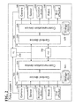
FIG. 2 is a block diagram illustrating the robot system according to the embodiment; -
FIG. 3 is a side view of another robot system according to the embodiment; and -
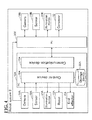
FIG. 4 is a block diagram illustrating still another robot system according to the embodiment. - The embodiments will now be described with reference to the accompanying drawings, wherein like reference numerals designate corresponding or identical elements throughout the various drawings.
- In a
robot system 1 according to this embodiment,robots cells robot system 1 is also referred to as a cell production system. The workpiece W may be any kind of item subject to work such as conveyance and assembly in therobot system 1. The to-be-worked material may be the workpiece W itself, or a product or a semi-processed product made of the workpiece W. The to-be-worked material may also be a product or a semi-processed product formed of a combination of a plurality of parts. Thecells robots robot system 1 of this embodiment. This improves the productivity of the workpieces W. - As shown in
FIG. 1 , therobot system 1 includes the twocells robot system 1 includes the twocells robot system 1 may include more than two cells. Thecells cell 100A will be described, with description of thecell 100B omitted. - The
cell 100A includes therobot 10A and acasing 110A. Therobot 10A performs various kinds of work on the workpiece W. Thecasing 110A accommodates therobot 10A. Thecasing 110A includes abottom wall 112A,side walls 114A, and atop wall 116A. Thebottom wall 112A has a rectangular shape and supports therobot 10A. Theside walls 114A are upright on the respective sides of thebottom wall 112A. Thetop wall 116A is disposed on the upper ends of theside walls 114A. Therobot 10A is accommodated in an accommodation space defined by thebottom wall 112A, theside walls 114A, and thetop wall 116A. - On the lower surface of the
bottom wall 112A,casters 118A andstoppers 120A are disposed. Thecasters 118A make thecell 100A movable, and thestoppers 120A fix thecell 100A. Oneside wall 114A among theside walls 114A that is in contact with thecasing 110B of thecell 100B has a communication hole HA. The communication hole HA communicates with a communication hole HB, which is formed on aside wall 114B. Thus, the accommodation spaces of thecasings cells - The
side wall 114A on the front side of thecell 100A is where the following operation parts, not shown, are collectively disposed: an opening through which the workpiece W is supplied and taken out; a monitor on which to check the work status of the robot; and various gauges and switches. This ensures that the operator only needs to be positioned on the front side of the cell 11 when operating therobot system 1. Theside walls 114A and thetop wall 116A each may have a window (not shown) on at least a part ofside walls 114A and thetop wall 116A. The window is made of a material (such as polycarbonate) superior in transparency and impact resistance, and thus enables the operator to check the work status of therobot 10A in thecasing 110A through the window. - The
cell 100A incorporates a work table 12A, atool box 14A, a robot controller (RC) 16A, acamera 18A, anillumination device 20A, and asensor 22A. The workpiece W is to be placed on the work table 12A. On the work table 12A, therobot 10A performs work on the workpiece W. - The
tool box 14A is disposed on the work table 12A and accommodates tools (end effectors) used by therobot 10A to perform work on the workpiece W. The tools include a hand, a driver, a rivet, a drill, and a portable camera. Therobot controller 16A is coupled to therobot 10A, thecamera 18A, theillumination device 20A, thesensor 22A, and thePLC 200, so as to transmit and receive information to and from these elements. In this embodiment, therobot controller 16A is disposed on the lower surface of the work table 12A and is coupled to therobot 10A through acable harness 24A. Therobot 10A and therobot controller 16A may be coupled to each other wirelessly, or therobot 10A may incorporate therobot controller 16A. - The
camera 18A is disposed on thetop wall 116A, and mainly captures an image of the work table 12A from above. Theillumination device 20A is disposed on thetop wall 116A. Theillumination device 20A may be any of various types of light sources. Examples include, but are not limited to, a flash that emits a flash of light, a light bulb, a fluorescent light, and an LED that continuously emit a predetermined amount of light. Thesensor 22A is disposed adjacent to thecamera 18A on thetop wall 116A. Thesensor 22A detects the intensity (for example, luminosity, brightness, and luminance) of the light received by thecamera 18A. - The
robot 10A is also referred to as a manipulator. Therobot 10A is disposed on thebottom wall 112A of thecasing 110A with abase 122A interposed between therobot 10A and thebottom wall 112A, and disposed by a side of the work table 12A. Therobot 10A operates based on an operation command output from therobot controller 16A. The operation command is a command as a program to activate the robot or a combination job of programs to activate the robot. - The
robot 10A includes first tosixth arms 10A1 to 10A6. Thefirst arm 10A1 is coupled to thebase 122A. The first tosixth arms 10A1 to 10A6 are coupled in series in this order from the based end side (thebase 122A). A coupling portion between thebase 122A and thefirst arm 10A1, and coupling portions between theadjacent arms 10A1 to 10A6 function as joints of therobot 10A. - The
robot 10A includes a plurality of actuators corresponding to the respective joints. The actuators bring therespective arms 10A1 to 10A6 into swing movement about the respective joints (see the arrows shown inFIG. 1 ). - The end effector EA may be a hand removably mounted to the
sixth arm 10A6, which is at the distal end of therobot 10A. The end effector EA is driven by the actuator incorporated in thesixth arm 10A6. When the end effector EA is a hand as shown inFIG. 1 , a pair of holder pieces are driven by the actuator to move closer to and away from each other. In this manner, the hand holds the workpiece W, changes the posture of the workpiece W, and conveys the held workpiece W. - The
PLC 200 controls therobots robot controllers PC 300 processes images captured by thecameras - Next, a system configuration of the
robot system 1 will be described by referring toFIG. 2 . Therobot system 1 includes therobot controllers robots cameras sensors illumination devices PLC 200, and thePC 300. - The
robot controller 16A includes acontrol device 26A, acommunication device 28A, and astorage device 30A. Thecontrol device 26A generates an operation command to control the operation of therobot 10A. Specifically, thecontrol device 26A is coupled to the actuators of therobot 10A through thecable harness 24A, and drives the actuators with the operation command, so as to control the operation of therobot 10A. - The
control device 26A controls thecamera 18A to capture an image of an imaging object (for example, a workpiece W on the work table 12A) that is included in the imaging area of thecamera 18A. Thecontrol device 26A receives the intensity of light detected by thesensor 22A in the form of a signal. Thecontrol device 26A controls theillumination device 20A to provide illumination while thecamera 18A is capturing the image. In order to enable thecamera 18A to receive desired light, thecontrol device 26A controls the intensity of light emitted from theillumination device 20A based on the signal received from thesensor 22A. - Upon receiving a signal from a detection sensor (not shown) that detects that the
cells control device 26A determines that the setting has been changed into a connection mode, in which the plurality ofcells control device 26A controls therobots 10A, the end effector EA, thecamera 18A, and theillumination device 20A to perform operations under connection mode. Examples of the detection sensor include, but are not limited to, a pressure sensor capable of detecting that theside walls side walls side walls control device 26A may use a plug-and-play system to change the setting to connection mode in response to the connection between the cables of thecells control device 26A and thecell 100B may be mutually coupled wirelessly. - When the setting is changed into connection mode, the
control device 26A opens the doors that have been respectively closing the communication holes HA and HB. This provides communication between the accommodation space of thecasing 110A and the accommodation space of thecasing 110B, enabling one robot in one casing to use the inside of the other casing. Thus, the work area of each robot is widened. - The
communication device 28A communicates with thecontrol device 26A and thePLC 200 to transmit to theother robot controller 16B (control device 26B) a signal indicating that the setting of thecontrol device 26A has been changed into connection mode. Thecommunication device 28A communicates with thecontrol device 26A and thePLC 200 to receive from theother robot controller 16B a signal indicating that the setting of thecontrol device 26B of theother robot controller 16B has been changed into connection mode. Thecommunication devices PLC 200, which is an upper device of therobot controllers communication devices - The
storage device 30A stores a command as a program for operating therobot 10A, the end effector EA, thecamera 18A, and theillumination device 20A, and stores a job as a set of such programs. When thecontrol device 26A reads the command or the job from thestorage device 30A, then therobot 10A, the end effector EA, thecamera 18A, or theillumination device 20A operates in accordance with the read command or job. - Incidentally, the
cells FIG. 1 , fluorescent lights L are disposed on the ceiling. In addition to these light sources, theadjacent cells illumination devices illumination devices cameras respective cameras controllers illumination devices - When the settings of the
controllers controller 26A and/or thecontroller 26B control at least one of theillumination devices camera 18A and/or thecamera 18B within the dynamic range of thecamera 18A and/or thecamera 18B when thecameras controller 26A and/or thecontroller 26B may adjust the intensity of light emitted from at least one of theillumination devices camera 18A and/or thecamera 18B within the dynamic range of thecamera 18A and/or thecamera 18B when thecameras controllers illumination devices cameras respective cameras cameras controller 26A and/or thecontroller 26B may control the emission direction of light emitted from at least one of theillumination devices illumination devices cameras respective cameras cameras controller 26A and/or thecontroller 26B may control at least one of theillumination devices sensor 22A and/or thesensor 22B. - For example, the workpiece W is conveyed into the
cell 100A. The workpiece W is then placed on the work table 12A. Thecamera 18A captures an image of the workpiece W based on an instruction from thecontrol device 26A. After thecamera 18A has captured an image of the workpiece W, data of the image is transmitted to thePC 300. ThePC 300 processes the image data to recognize the position and posture of the workpiece W imaged by thecamera 18A. Then, thePC 300 transmits the recognized position and posture of the workpiece W to therobot controller 16A (communication device 28A). Based on the data on the position and posture of the workpiece W, thecontrol device 26A controls therobot 10A and the end effector EA to perform a predetermined work on the workpiece W. When the work is complete, the workpiece W is taken out of thecell 100A (for example, to thecell 100B). Thus, the workpiece W is produced. - In the above-described embodiment, the
controller 26A and/or thecontroller 26B control at least one of theillumination devices camera 18A and/or thecamera 18B within the dynamic range of thecamera 18A and/or thecamera 18B when thecameras cameras cameras robots - In this embodiment, the
controller 26A and/or thecontroller 26B control at least one of theillumination devices sensor 22A and/or thesensor 22B. This ensures automatic adjustment of the intensity of light and the timing at which each of theillumination devices cells - It is noted that the above-described embodiment is provided for exemplary purposes only and is not intended in a limiting sense. For example, the
controllers cells illumination devices cells illumination devices cells - The
controllers cameras illumination devices cells illumination devices cells - The
controllers cameras cameras cameras illumination devices cells illumination devices cells - In the above-described embodiment, the
robot system 1 has been illustrated as a cell production system including thecells robot system 1 is also applicable to any robot system other than the cell production system. Specifically, as shown inFIGs. 3 and4 , the robot system 2 includes aconveyor 32, arobot 10A,cameras illumination devices sensors conveyor 32 transfers at least one workpiece W in a predetermined direction. Therobot 10A is disposed by a side of theconveyor 32. - In the robot system 2, the
camera 18A, theillumination device 20A, and thesensor 22A are used to recognize the position and posture of the workpiece W while therobot 10A is working on the workpiece W. In the robot system 2, thecamera 18B, theillumination device 20B, and thesensor 22B are disposed on an upstream side of thecamera 18A, theillumination device 20A, thesensor 22A, and therobot 10A in the direction in which the workpiece W is transferred by theconveyor 32. Thecamera 18B, theillumination device 20B, and thesensor 22B are used, for example, to inspect the external appearance of the workpiece W. Thecamera 18B, theillumination device 20B, thesensor 22B, and theconveyor 32 are coupled to thecomputer 300. - The
computer 300 controls operations of thecamera 18B, theillumination device 20B, and theconveyor 32. Thecomputer 300 receives the intensity of light detected by thesensor 22B in the form of a signal. - Based on an instruction of the
computer 300, thecamera 18B captures an image of the workpiece W. Then, image data of the captured image is transmitted to thecomputer 300. Thecomputer 300 processes the image data to inspect whether the workpiece W includes a defect (for example, chipping, breaking, and cracks). As a result of the appearance inspection by thecomputer 300, when thecomputer 300 determines that the workpiece W is non-defective, thecomputer 300 transmits the determination result to therobot controller 16A. Thecontrol device 26A receives the determination result through thecommunication device 28A, and then controls therobot 10A and/or the end effector EA to perform work on the workpiece W determined as non-defective when the workpiece W is transferred to therobot 10A by theconveyor 32. - Meanwhile, as the result of the appearance inspection by the
computer 300, when thecomputer 300 determines that the workpiece W is defective, thecomputer 300 transmits the determination result to therobot controller 16A. Thecontrol device 26A receives the determination result through thecommunication device 28A, and controls therobot 10A and/or the end effector EA not to perform work on the workpiece W determined as defective, even though the workpiece W is transferred to therobot 10A by theconveyor 32. - The robot system 2 is also installed in factories and other institutions that contain various light sources including natural light. For example, in
FIG. 3 , fluorescent lights L are disposed on the ceiling. In addition to these light sources, theillumination devices conveyor 32. If theillumination devices cameras respective cameras - In view of this, in the robot system 2, the
control device 26A and thecomputer 300 control at least one of theillumination devices camera 18A and/or thecamera 18B within the dynamic range of thecamera 18A and/or thecamera 18B when thecameras cameras - 1,2
- Robot system
- 10A, 10B
- Robot
- 16A, 16B
- Robot controller (RC)
- 18A, 18B
- Camera
- 20A, 20B
- Illumination device
- 22A, 22B
- Sensor
- 26A, 26B
- Control device
- 100A, 100B
- Cell
- 200
- Programmable logic controller (PLC)
- 300
- Computer (PC)
- W
- Workpiece (to-be-processed material)
Claims (8)
- A robot system 1, 2, characterized by:a robot 10A, 10B configured to perform a predetermined work on a to-be-processed material;an image capture device 18A, 18B configured to capture an image of the to-be-processed material;a plurality of illumination devices 20A, 20B configured to illuminate the to-be-processed material; anda control device 26A, 26B configured to control at least one illumination device 20A, 20B among the plurality of illumination devices 20A, 20B to keep an amount of light received by the image capture device 18A, 18B within dynamic range of the image capture device 18A, 18B.
- The robot system 1, 2 according to claim 1, wherein the control device 26A, 26B is configured to adjust an intensity of light emitted from at least one illumination device 20A, 20B among the plurality of illumination devices 20A, 20B.
- The robot system 1, 2 according to claim 1, wherein the control device 26A, 26B is configured to control the plurality of illumination devices 20A, 20B to operate at different timings.
- The robot system 1, 2 according to claim 1, wherein the control device 26A, 26B is configured to control an emission direction of light emitted from at least one illumination device 20A, 20B among the plurality of illumination devices 20A, 20B.
- The robot system 1, 2 according to any one of claims 1 to 4, further comprising a sensor 22A, 22B configured to detect an intensity of light,
wherein the control device 26A, 26B is configured to control the at least one illumination device 20A, 20B among the plurality of illumination devices 20A, 20B in accordance with the intensity of the light detected by the sensor 22A, 22B. - The robot system 1, 2 according to any one of claims 1 to 5, wherein the robot 10A, 10B comprises a plurality of robots 10A, 10B respectively accommodated in independent casings 110A, 110B.
- The robot system 1, 2 according to claim 6, wherein the image capture device 18A, 18B and the illumination device 20A, 20B are disposed in each one casing 110A, 110B among the casings 110A, 110B.
- A method for producing a to-be-processed material using the robot system 1, 2 according to any one of claims 1 to 7, characterized by:transferring the to-be-processed material to an operation area of the robot 10A, 10B;controlling the robot 10A, 10B to perform a predetermined operation on the to-be-processed material; andtaking out the to-be-processed material done with the predetermined operation by the robot 10A, 10B from the operation area of the robot 10A, 10B.
Applications Claiming Priority (1)
| Application Number | Priority Date | Filing Date | Title |
|---|---|---|---|
| JP2013053291A JP5776716B2 (en) | 2013-03-15 | 2013-03-15 | Robot system and workpiece manufacturing method |
Publications (2)
| Publication Number | Publication Date |
|---|---|
| EP2783803A2 true EP2783803A2 (en) | 2014-10-01 |
| EP2783803A3 EP2783803A3 (en) | 2015-06-03 |
Family
ID=50189590
Family Applications (1)
| Application Number | Title | Priority Date | Filing Date |
|---|---|---|---|
| EP14157432.7A Withdrawn EP2783803A3 (en) | 2013-03-15 | 2014-03-03 | Robot system and method for producing to-be-processed material |
Country Status (4)
| Country | Link |
|---|---|
| US (1) | US9132554B2 (en) |
| EP (1) | EP2783803A3 (en) |
| JP (1) | JP5776716B2 (en) |
| CN (1) | CN104044142B (en) |
Cited By (1)
| Publication number | Priority date | Publication date | Assignee | Title |
|---|---|---|---|---|
| EP3675486A1 (en) * | 2018-12-27 | 2020-07-01 | Canon Kabushiki Kaisha | Control device, industrial automation system, method of controlling control device, program, and non-transitory computer-readable storage medium |
Families Citing this family (19)
| Publication number | Priority date | Publication date | Assignee | Title |
|---|---|---|---|---|
| JP6392581B2 (en) * | 2014-08-20 | 2018-09-19 | ファナック株式会社 | Robot control device and processing system for robots used with machine tools |
| JP2016203347A (en) * | 2015-04-28 | 2016-12-08 | セイコーエプソン株式会社 | Robot system and robot |
| EP3290168A4 (en) * | 2015-04-28 | 2018-12-12 | Seiko Epson Corporation | Robot system and robot |
| JP2016203348A (en) * | 2015-04-28 | 2016-12-08 | セイコーエプソン株式会社 | Robot system |
| JP6540196B2 (en) * | 2015-04-28 | 2019-07-10 | セイコーエプソン株式会社 | Robot system |
| JP6581808B2 (en) | 2015-05-22 | 2019-09-25 | 川崎重工業株式会社 | Camera cover and imaging system having the same |
| JP6554946B2 (en) * | 2015-07-03 | 2019-08-07 | 株式会社デンソーウェーブ | Robot system |
| JP6554945B2 (en) * | 2015-07-03 | 2019-08-07 | 株式会社デンソーウェーブ | Robot system |
| JP6464945B2 (en) * | 2015-07-03 | 2019-02-06 | 株式会社デンソーウェーブ | Robot system |
| JP7156818B2 (en) * | 2018-05-15 | 2022-10-19 | 川崎重工業株式会社 | Robot system and its operation method |
| ES2919649T3 (en) * | 2018-06-19 | 2022-07-27 | Bae Systems Plc | workbench system |
| CN110962396B (en) * | 2018-09-30 | 2023-05-26 | 上海东冠纸业有限公司 | Anti-blocking bag system of soft tissue paper production line |
| US12106188B2 (en) | 2018-10-26 | 2024-10-01 | George K. Ghanem | Learning software assisted fixtureless object pickup and placement system and method |
| US12134193B2 (en) * | 2018-10-26 | 2024-11-05 | George K. Ghanem | Learning software assisted object joining |
| US12214496B2 (en) * | 2018-10-26 | 2025-02-04 | George K. Ghanem | Learning software assisted automated manufacture |
| US11559897B2 (en) | 2018-10-26 | 2023-01-24 | George K. Ghanem | Reconfigurable, fixtureless manufacturing system and method assisted by learning software |
| JP7561519B2 (en) * | 2020-05-22 | 2024-10-04 | 株式会社アマダ | Bending system and method of using same |
| WO2022162978A1 (en) * | 2021-01-27 | 2022-08-04 | 株式会社Pfu | Object recognition device and object processing device |
| WO2022168350A1 (en) * | 2021-02-03 | 2022-08-11 | 株式会社Pfu | Object recognition device and object processing device |
Citations (2)
| Publication number | Priority date | Publication date | Assignee | Title |
|---|---|---|---|---|
| JP2010188459A (en) | 2009-02-17 | 2010-09-02 | Fanuc Ltd | Production system using part kit |
| JP2012011501A (en) | 2010-06-30 | 2012-01-19 | Canon Inc | Production system |
Family Cites Families (15)
| Publication number | Priority date | Publication date | Assignee | Title |
|---|---|---|---|---|
| US4613269A (en) | 1984-02-28 | 1986-09-23 | Object Recognition Systems, Inc. | Robotic acquisition of objects by means including histogram techniques |
| US4979135A (en) * | 1988-01-27 | 1990-12-18 | Storage Technology Corporation | Vision system illumination calibration apparatus |
| US5479252A (en) * | 1993-06-17 | 1995-12-26 | Ultrapointe Corporation | Laser imaging system for inspection and analysis of sub-micron particles |
| US5500732A (en) * | 1994-06-10 | 1996-03-19 | Johnson & Johnson Vision Products, Inc. | Lens inspection system and method |
| US6956963B2 (en) * | 1998-07-08 | 2005-10-18 | Ismeca Europe Semiconductor Sa | Imaging for a machine-vision system |
| JP2006021300A (en) * | 2004-07-09 | 2006-01-26 | Sharp Corp | Estimation device and gripping device |
| US7720315B2 (en) * | 2004-11-12 | 2010-05-18 | Cognex Technology And Investment Corporation | System and method for displaying and using non-numeric graphic elements to control and monitor a vision system |
| JP4247213B2 (en) * | 2005-07-20 | 2009-04-02 | ファナック株式会社 | Robot system including a plurality of robot control devices and robot control device |
| JP5449728B2 (en) * | 2008-09-24 | 2014-03-19 | シャープ株式会社 | Inspection device |
| JP5175245B2 (en) * | 2009-06-22 | 2013-04-03 | 承奕科技股▲ふん▼有限公司 | Light source device |
| US8244402B2 (en) * | 2009-09-22 | 2012-08-14 | GM Global Technology Operations LLC | Visual perception system and method for a humanoid robot |
| JP2012074785A (en) * | 2010-09-28 | 2012-04-12 | Nec Casio Mobile Communications Ltd | Imaging apparatus and control method of the same |
| JP5653166B2 (en) * | 2010-10-22 | 2015-01-14 | キヤノン株式会社 | Robot cell |
| JP5316580B2 (en) * | 2011-05-17 | 2013-10-16 | 株式会社安川電機 | Robot system |
| KR101283079B1 (en) * | 2011-08-17 | 2013-07-05 | 엘지이노텍 주식회사 | Network camera with infrared led light |
-
2013
- 2013-03-15 JP JP2013053291A patent/JP5776716B2/en not_active Expired - Fee Related
-
2014
- 2014-01-27 CN CN201410040757.3A patent/CN104044142B/en not_active Expired - Fee Related
- 2014-02-27 US US14/191,427 patent/US9132554B2/en not_active Expired - Fee Related
- 2014-03-03 EP EP14157432.7A patent/EP2783803A3/en not_active Withdrawn
Patent Citations (2)
| Publication number | Priority date | Publication date | Assignee | Title |
|---|---|---|---|---|
| JP2010188459A (en) | 2009-02-17 | 2010-09-02 | Fanuc Ltd | Production system using part kit |
| JP2012011501A (en) | 2010-06-30 | 2012-01-19 | Canon Inc | Production system |
Cited By (1)
| Publication number | Priority date | Publication date | Assignee | Title |
|---|---|---|---|---|
| EP3675486A1 (en) * | 2018-12-27 | 2020-07-01 | Canon Kabushiki Kaisha | Control device, industrial automation system, method of controlling control device, program, and non-transitory computer-readable storage medium |
Also Published As
| Publication number | Publication date |
|---|---|
| CN104044142A (en) | 2014-09-17 |
| US9132554B2 (en) | 2015-09-15 |
| EP2783803A3 (en) | 2015-06-03 |
| JP2014176937A (en) | 2014-09-25 |
| JP5776716B2 (en) | 2015-09-09 |
| CN104044142B (en) | 2015-12-02 |
| US20140277733A1 (en) | 2014-09-18 |
Similar Documents
| Publication | Publication Date | Title |
|---|---|---|
| US9132554B2 (en) | Robot system and method for producing to-be-processed material | |
| US9158299B2 (en) | Robot system and method for producing to-be-worked material | |
| TWI611883B (en) | Industrial remote operating robot system | |
| US9329593B2 (en) | Robot system, method for controlling robot, and method for producing to-be-processed material | |
| US10625953B2 (en) | Robot | |
| US20220016789A1 (en) | Tool stocker, interchangeable tool, robot apparatus, robot system, control method of robot system, and storage medium | |
| US20180151399A1 (en) | Substrate transfer device | |
| KR101601217B1 (en) | Tire inspection device and method | |
| TW202043128A (en) | Robot hand, robot, and robot system | |
| EP2915597A1 (en) | Programmable digital machine vision inspection system | |
| WO2015194659A1 (en) | Worker terminal for robot operation | |
| WO2015011782A1 (en) | Inspection apparatus | |
| US10864643B2 (en) | Substrate conveying apparatus | |
| US20150343639A1 (en) | Gear incorporation system and gear incorporation method | |
| Prusaczyk et al. | Integration of robotic arm and vision system with processing software using TCP/IP protocol in industrial sorting application | |
| KR20260010293A (en) | Cooperative Robot, Method for Controlling the Robot, and System Including the Same | |
| JP2017170550A (en) | Control apparatus, robot, and robot system | |
| JP4543001B2 (en) | Information communication system used in robots | |
| US20200338740A1 (en) | Control Method By Robot System And Robot System | |
| JP2009172720A (en) | Bin picking device | |
| JP2020151770A (en) | Flexible manufacturing system | |
| JP2020187708A (en) | Machine tool, action type discrimination method, and action type discrimination program | |
| KR20230112359A (en) | Multi-joint robot having vision inspection fuction | |
| JP6818291B2 (en) | Parts supply equipment and method | |
| JP6291793B2 (en) | Robot and robot system |
Legal Events
| Date | Code | Title | Description |
|---|---|---|---|
| 17P | Request for examination filed |
Effective date: 20140303 |
|
| AK | Designated contracting states |
Kind code of ref document: A2 Designated state(s): AL AT BE BG CH CY CZ DE DK EE ES FI FR GB GR HR HU IE IS IT LI LT LU LV MC MK MT NL NO PL PT RO RS SE SI SK SM TR |
|
| AX | Request for extension of the european patent |
Extension state: BA ME |
|
| PUAI | Public reference made under article 153(3) epc to a published international application that has entered the european phase |
Free format text: ORIGINAL CODE: 0009012 |
|
| PUAL | Search report despatched |
Free format text: ORIGINAL CODE: 0009013 |
|
| AK | Designated contracting states |
Kind code of ref document: A3 Designated state(s): AL AT BE BG CH CY CZ DE DK EE ES FI FR GB GR HR HU IE IS IT LI LT LU LV MC MK MT NL NO PL PT RO RS SE SI SK SM TR |
|
| AX | Request for extension of the european patent |
Extension state: BA ME |
|
| RIC1 | Information provided on ipc code assigned before grant |
Ipc: B25J 9/16 20060101AFI20150424BHEP |
|
| R17P | Request for examination filed (corrected) |
Effective date: 20150618 |
|
| RBV | Designated contracting states (corrected) |
Designated state(s): AL AT BE BG CH CY CZ DE DK EE ES FI FR GB GR HR HU IE IS IT LI LT LU LV MC MK MT NL NO PL PT RO RS SE SI SK SM TR |
|
| 17Q | First examination report despatched |
Effective date: 20160621 |
|
| STAA | Information on the status of an ep patent application or granted ep patent |
Free format text: STATUS: THE APPLICATION IS DEEMED TO BE WITHDRAWN |
|
| 18D | Application deemed to be withdrawn |
Effective date: 20161103 |