EP2783660A1 - Finger assisting device - Google Patents
Finger assisting device Download PDFInfo
- Publication number
- EP2783660A1 EP2783660A1 EP14161083.2A EP14161083A EP2783660A1 EP 2783660 A1 EP2783660 A1 EP 2783660A1 EP 14161083 A EP14161083 A EP 14161083A EP 2783660 A1 EP2783660 A1 EP 2783660A1
- Authority
- EP
- European Patent Office
- Prior art keywords
- finger
- contact force
- force
- drive
- threshold value
- Prior art date
- Legal status (The legal status is an assumption and is not a legal conclusion. Google has not performed a legal analysis and makes no representation as to the accuracy of the status listed.)
- Granted
Links
- 238000005452 bending Methods 0.000 claims abstract description 68
- 230000007423 decrease Effects 0.000 claims description 22
- 239000000463 material Substances 0.000 claims description 8
- 238000000034 method Methods 0.000 claims 6
- 210000003811 finger Anatomy 0.000 description 239
- 238000010586 diagram Methods 0.000 description 15
- 230000003247 decreasing effect Effects 0.000 description 13
- 239000002184 metal Substances 0.000 description 4
- 239000011347 resin Substances 0.000 description 3
- 229920005989 resin Polymers 0.000 description 3
- 206010044565 Tremor Diseases 0.000 description 2
- 241001465754 Metazoa Species 0.000 description 1
- 230000032683 aging Effects 0.000 description 1
- 201000010099 disease Diseases 0.000 description 1
- 208000037265 diseases, disorders, signs and symptoms Diseases 0.000 description 1
- 238000005516 engineering process Methods 0.000 description 1
- 230000005057 finger movement Effects 0.000 description 1
- 230000006870 function Effects 0.000 description 1
- 210000004247 hand Anatomy 0.000 description 1
- 210000004932 little finger Anatomy 0.000 description 1
- 210000003813 thumb Anatomy 0.000 description 1
Images


Classifications
-
- A—HUMAN NECESSITIES
- A61—MEDICAL OR VETERINARY SCIENCE; HYGIENE
- A61H—PHYSICAL THERAPY APPARATUS, e.g. DEVICES FOR LOCATING OR STIMULATING REFLEX POINTS IN THE BODY; ARTIFICIAL RESPIRATION; MASSAGE; BATHING DEVICES FOR SPECIAL THERAPEUTIC OR HYGIENIC PURPOSES OR SPECIFIC PARTS OF THE BODY
- A61H1/00—Apparatus for passive exercising; Vibrating apparatus; Chiropractic devices, e.g. body impacting devices, external devices for briefly extending or aligning unbroken bones
- A61H1/02—Stretching or bending or torsioning apparatus for exercising
- A61H1/0274—Stretching or bending or torsioning apparatus for exercising for the upper limbs
- A61H1/0285—Hand
- A61H1/0288—Fingers
-
- A—HUMAN NECESSITIES
- A61—MEDICAL OR VETERINARY SCIENCE; HYGIENE
- A61F—FILTERS IMPLANTABLE INTO BLOOD VESSELS; PROSTHESES; DEVICES PROVIDING PATENCY TO, OR PREVENTING COLLAPSING OF, TUBULAR STRUCTURES OF THE BODY, e.g. STENTS; ORTHOPAEDIC, NURSING OR CONTRACEPTIVE DEVICES; FOMENTATION; TREATMENT OR PROTECTION OF EYES OR EARS; BANDAGES, DRESSINGS OR ABSORBENT PADS; FIRST-AID KITS
- A61F2/00—Filters implantable into blood vessels; Prostheses, i.e. artificial substitutes or replacements for parts of the body; Appliances for connecting them with the body; Devices providing patency to, or preventing collapsing of, tubular structures of the body, e.g. stents
- A61F2/50—Prostheses not implantable in the body
- A61F2/54—Artificial arms or hands or parts thereof
- A61F2/58—Elbows; Wrists ; Other joints; Hands
- A61F2/583—Hands; Wrist joints
- A61F2/586—Fingers
-
- A—HUMAN NECESSITIES
- A61—MEDICAL OR VETERINARY SCIENCE; HYGIENE
- A61F—FILTERS IMPLANTABLE INTO BLOOD VESSELS; PROSTHESES; DEVICES PROVIDING PATENCY TO, OR PREVENTING COLLAPSING OF, TUBULAR STRUCTURES OF THE BODY, e.g. STENTS; ORTHOPAEDIC, NURSING OR CONTRACEPTIVE DEVICES; FOMENTATION; TREATMENT OR PROTECTION OF EYES OR EARS; BANDAGES, DRESSINGS OR ABSORBENT PADS; FIRST-AID KITS
- A61F2/00—Filters implantable into blood vessels; Prostheses, i.e. artificial substitutes or replacements for parts of the body; Appliances for connecting them with the body; Devices providing patency to, or preventing collapsing of, tubular structures of the body, e.g. stents
- A61F2/50—Prostheses not implantable in the body
- A61F2/68—Operating or control means
- A61F2/70—Operating or control means electrical
-
- A—HUMAN NECESSITIES
- A61—MEDICAL OR VETERINARY SCIENCE; HYGIENE
- A61F—FILTERS IMPLANTABLE INTO BLOOD VESSELS; PROSTHESES; DEVICES PROVIDING PATENCY TO, OR PREVENTING COLLAPSING OF, TUBULAR STRUCTURES OF THE BODY, e.g. STENTS; ORTHOPAEDIC, NURSING OR CONTRACEPTIVE DEVICES; FOMENTATION; TREATMENT OR PROTECTION OF EYES OR EARS; BANDAGES, DRESSINGS OR ABSORBENT PADS; FIRST-AID KITS
- A61F5/00—Orthopaedic methods or devices for non-surgical treatment of bones or joints; Nursing devices ; Anti-rape devices
- A61F5/01—Orthopaedic devices, e.g. long-term immobilising or pressure directing devices for treating broken or deformed bones such as splints, casts or braces
- A61F5/0102—Orthopaedic devices, e.g. long-term immobilising or pressure directing devices for treating broken or deformed bones such as splints, casts or braces specially adapted for correcting deformities of the limbs or for supporting them; Ortheses, e.g. with articulations
- A61F5/013—Orthopaedic devices, e.g. long-term immobilising or pressure directing devices for treating broken or deformed bones such as splints, casts or braces specially adapted for correcting deformities of the limbs or for supporting them; Ortheses, e.g. with articulations for the arms, hands or fingers
-
- A—HUMAN NECESSITIES
- A61—MEDICAL OR VETERINARY SCIENCE; HYGIENE
- A61H—PHYSICAL THERAPY APPARATUS, e.g. DEVICES FOR LOCATING OR STIMULATING REFLEX POINTS IN THE BODY; ARTIFICIAL RESPIRATION; MASSAGE; BATHING DEVICES FOR SPECIAL THERAPEUTIC OR HYGIENIC PURPOSES OR SPECIFIC PARTS OF THE BODY
- A61H2201/00—Characteristics of apparatus not provided for in the preceding codes
- A61H2201/16—Physical interface with patient
- A61H2201/1602—Physical interface with patient kind of interface, e.g. head rest, knee support or lumbar support
- A61H2201/1635—Hand or arm, e.g. handle
-
- A—HUMAN NECESSITIES
- A61—MEDICAL OR VETERINARY SCIENCE; HYGIENE
- A61H—PHYSICAL THERAPY APPARATUS, e.g. DEVICES FOR LOCATING OR STIMULATING REFLEX POINTS IN THE BODY; ARTIFICIAL RESPIRATION; MASSAGE; BATHING DEVICES FOR SPECIAL THERAPEUTIC OR HYGIENIC PURPOSES OR SPECIFIC PARTS OF THE BODY
- A61H2201/00—Characteristics of apparatus not provided for in the preceding codes
- A61H2201/50—Control means thereof
- A61H2201/5058—Sensors or detectors
- A61H2201/5061—Force sensors
-
- A—HUMAN NECESSITIES
- A61—MEDICAL OR VETERINARY SCIENCE; HYGIENE
- A61H—PHYSICAL THERAPY APPARATUS, e.g. DEVICES FOR LOCATING OR STIMULATING REFLEX POINTS IN THE BODY; ARTIFICIAL RESPIRATION; MASSAGE; BATHING DEVICES FOR SPECIAL THERAPEUTIC OR HYGIENIC PURPOSES OR SPECIFIC PARTS OF THE BODY
- A61H2205/00—Devices for specific parts of the body
- A61H2205/06—Arms
- A61H2205/065—Hands
-
- A—HUMAN NECESSITIES
- A61—MEDICAL OR VETERINARY SCIENCE; HYGIENE
- A61H—PHYSICAL THERAPY APPARATUS, e.g. DEVICES FOR LOCATING OR STIMULATING REFLEX POINTS IN THE BODY; ARTIFICIAL RESPIRATION; MASSAGE; BATHING DEVICES FOR SPECIAL THERAPEUTIC OR HYGIENIC PURPOSES OR SPECIFIC PARTS OF THE BODY
- A61H2205/00—Devices for specific parts of the body
- A61H2205/06—Arms
- A61H2205/065—Hands
- A61H2205/067—Fingers
Definitions
- the present invention relates to a finger assist device.
- Patent Document 1 JP-A-2002-345861
- Patent Document 2 JP-A-2011-115248
- An advantage of some aspects of the invention is to provide a technology that may appropriately assist bending movement or spreading movement of a finger by detecting a person's intention to bend or spread the finger.
- a finger assist device employs the following configuration. That is, a finger assist device worn on a finger and assisting movement of bending the finger includes a plurality of units rotatably connected in a bending direction in which the finger bends and a spreading direction in which the finger spreads in an opposite direction to the bending direction, suppose that a side facing an object to be grasped by the finger is a pad of the finger and an opposite side of the pad of the finger is a back of the finger, a nipping part provided in each of the plurality of units and nipping the pad of the finger and the back of the finger, at least one of a first sensor that detects a first contact force generated between the nipping part and the pad of the hand finger and a second sensor that detects a second contact force generated between the nipping part and the back of the hand finger provided in the nipping part, a drive part connected to the unit and rotationally driving the unit in the direction in which the finger bends or the direction in which the
- the finger assist device assists the movement of the finger by rotationally driving the connected plurality of units in the direction in which the finger bends or the direction in which the finger spreads.
- the unit is attached to the finger by nipping the finger with the nipping part from the pad and the back of the finger.
- finger pad refers to a side at which the finger faces an object when the finger is bent for grasping the object.
- finger back refers to an opposite side to the finger pad.
- the drive force is controlled by detecting the contact force between the finger pad and the nipping part (first contact force) and the contact force between the finger back and the nipping part (second contact force).
- the drive force of the finger assist device is appropriately controlled according to the wearer's intention in this manner, and thereby, bending movement and spreading movement of the finger may be appropriately assisted.
- the drive force in the state in which the unit is rotationally driven in the bending direction of the finger, the drive force may be increased and decreased in the following manner. That is, the drive force may be increased if the first contact force is larger than the second contact force and the drive force may be decreased if the first contact force is smaller than the second contact force.
- the case where the first contact force is larger than the second contact force in the state in which the unit is rotationally driven in the bending direction of the finger is considered as the case where the wearer tends to further bend the finger.
- the case where the first contact force is smaller than the second contact force is considered as the case where the wearer tends to weaken the force for bending the finger. Therefore, the contact forces are detected in the above described manner, and thereby, the drive force may be increased or decreased according to the wearer's intention.
- the drive force may not be increased or decreased. That is, in the state in which the unit is rotationally driven in the bending direction of the finger, if the first contact force is larger than the second contract force by a first increase-side threshold value or more, the drive force is increased, and if the second contact force is larger than the first contract force by a first decrease-side threshold value or more, the drive force is decreased.
- the drive force may be maintained.
- the threshold value at the side at which the drive force is increased (first increase-side threshold value) and the threshold value at the side at which the drive force is decreased (first decrease-side threshold value) are sufficient as long as they may be individually set, and the first increase-side threshold value and the first decrease-side threshold value may be set to the same value.
- the drive force in the state in which the unit is rotationally driven in the spreading direction, the drive force may be increased and decreased in the following manner. That is, the drive force may be decreased if the first contact force is larger than the second contact force and the drive force may be increased if the first contact force is smaller than the second contact force.
- the drive force may be increased or decreased according to the wearer's intention.
- the drive force may not be increased or decreased. That is, in the state in which the unit is rotationally driven in the spreading direction, if the second contact force is larger than the first contract force by a second increase-side threshold value or more, the drive force is increased, and if the first contact force is larger than the second contract force by a second decrease-side threshold value or more, the drive force is decreased.
- the drive force may be maintained.
- the threshold value at the side at which the drive force is increased (second increase-side threshold value) and the threshold value at the side at which the drive force is decreased (second decrease-side threshold value) are sufficient as long as they may be individually set, and the second increase-side threshold value and the second decrease-side threshold value may be set to the same value.
- the second increase-side threshold value may be set to be a smaller value than the first increase-side threshold value and the second decrease-side threshold value may be set to be a smaller value than the first decrease-side threshold value.
- the force of the finger is smaller than that at bending. Therefore, by setting the second increase-side threshold value to be the smaller value than the first increase-side threshold value and the second decrease-side threshold value to be the smaller value than the first decrease-side threshold value, at spreading of the finger, the movement of the finger may be assisted from when the finger is subject to the smaller force than that at bending.
- the first sensor and the second sensor may be provided especially in the nipping part of the unit at the tip end side of the finger among the units.
- the first sensor and the second sensor may be provided in the nipping parts of the other units.
- the wearer's intention may be sensitively sensed and the movement of the finger may be appropriately assisted.
- a first nipping portion provided on the finger pad may be formed more deformably than a second nipping portion provided on the finger back.
- a feeling of grasping the object is transmitted to the finger pad of the wearer via the first nipping portion, and a finger assist device that may easily grasp an object may be realized.
- a vibrator formed to contain a piezoelectric material may be used as the drive part for rotationally driving the unit.
- a bending vibration-type piezo-actuator may be preferably used.
- a thinner vibrator enables a thinner finger assist device. Further, the vibrator is pressed against a connecting member for use, and thus, while the connecting member is not rotationally driven, the vibrator functions as a brake for preventing rotation of the connecting member. Accordingly, even when the connecting member is not driven by the vibrator, the finger does not lean back due to the load.
- Figs. 1A and 1B are explanatory diagrams showing a state in which a finger assist device 100 of an embodiment is worn on a finger 1 (index finger) of a hand of a human.
- Fig. 1A shows the state seen from a pad of the finger 1
- Fig. 1B shows the state seen from a side surface side of the finger 1.
- the sign 1a shown in Figs. 1A and 1B denotes a nail of the finger 1
- the sign 1b denotes a fork of the finger 1
- the signs 1c denote joints of the finger 1.
- “finger pad” refers to a side at which the finger 1 faces an object when the finger 1 is bent for grasping the object.
- “finger back” refers to an opposite side to the finger pad. Note that, in the embodiment, the case where the device is worn on the finger 1 of the hand of the human is explained, however, the device may be worn on a finger of a shoe or a finger of a hand or shoe of an animal,
- the finger assist device 100 of the embodiment includes a plurality of (two in the illustrated example) series-connected drive units 110, and a finger tip unit 120 connected to a tip end.
- the same two drive units 110 are used, and, when it is necessary to distinguish the units, they are respectively referred to as drive units 110a, 110b as shown in Figs. 1A and 1B .
- the drive unit 110 of the embodiment corresponds to "unit" in the invention.
- the drive unit 110 includes a first member 111 provided at the side of the finger 1, a second member 112 provided at the opposite side to the finger 1 with the first member 111 in between, a rotor 113 having a disc shape and provided between the first member 111 and the second member 112, a piezoelectric motor 200 that rotates the rotor 113, a first spur gear 114 that rotates with the rotor 113, a second spur gear 115 fitted with the first spur gear 114, and connecting screws 116 that connect the first spur gear 114 to the second member 112 of the adjacent drive unit 110. Therefore, the respective drive units 110 may be freely attached and detached by fastening and loosening the connecting screws 116.
- the piezoelectric motor 200 is connected to a drive control unit 250 that controls the driving direction and the drive force of the piezoelectric motor 200 by supplying drive signals.
- the piezoelectric motor 200 of the embodiment corresponds to "drive part” or “vibrator” in the invention
- the drive control part 250 of the embodiment corresponds to a “drive force control part” in the invention.
- a first nipping portion 130b and a second nipping portion 130a are provided in each of the first member 111 of the drive unit 110a, the first member 111 of the drive unit 110b, and the finger tip unit 120, and the first nipping portion 130b nips the finger 1 from the pad of the finger 1 and the second nipping portion 130a nips the finger 1 from the back of the finger 1. Accordingly, as shown in Figs. 1A and 1B , the finger 1 is nipped by the first nipping portions 130b and the second nipping portions 130a provided in the drive units 110a, 110b and the finger tip unit 120, and thereby, the finger assist device 100 of the embodiment may be worn on the finger 1.
- the second nipping portion 130a is formed using a non-deformable material including metal or hard resin
- the first nipping portion 130b is formed using a deformable material including soft resin. Accordingly, even when grasping an object with the finger assist device 100 worn on the finger 1, the wearer may feel a sense of grasping the object with the pad of the finger 1 via the first nipping portions 130b.
- the first nipping portion 130b and the second nipping portion 130a of the embodiment correspond to "nipping part" in the invention.
- Fig. 1C shows a sectional view of the finger tip unit 120 cut along A-A.
- a first sensor 132b is provided in a position in contact with the pad of the finger 1 in the first nipping portion 130b of the finger tip unit 120.
- a second sensor 132a is provided in a position in contact with the back of the finger 1 in the second nipping portion 130a of the finger tip unit 120. Accordingly, when the finger assist device 100 of the embodiment is worn on the finger 1, the pad of the finger 1 is in contact with and lightly pressed against the first sensor 132b, and the back of the finger 1 is in contact with and lightly pressed against the second sensor 132a.
- the output from the first sensor 132b and the second sensor 132a is supplied to the drive control part 250. Further, the drive control part 250 drives the piezoelectric motor 200 based on the output from the first sensor 132b and the second sensor 132a. This point will be explained in detail later. Note that, in the embodiment, the explanation that the first sensor 132b and the second sensor 132a are attached only to the first nipping portion 130b and the second nipping portion 130a of the finger tip unit 120 is made, however, the first sensor 132b and the second sensor 132a may be attached to the first nipping portions 130b and the second nipping portions 130a of the drive units 110a, 110b.
- Figs. 2A to 2C are explanatory diagrams showing a detailed structure of the drive unit 110. Note that, in Figs. 2A to 2C , the illustration of attachment portions 102, 104 is omitted.
- Fig. 2A is a front view of the drive unit 110 seen from the opposite side to the side worn on the finger 1 (the side of the second member 112)
- Fig. 2B is a sectional view of the drive unit 110 in the center position
- Fig. 2C is a rear view of the drive unit 110 seen from the side worn on the finger 1 (the side of the first member 111).
- bosses 111b having cylindrical shapes are projected in two locations and the piezoelectric motor 200 is screwed on the top surfaces of the bosses 111b.
- the structure of the piezoelectric motor 200 will be described later.
- the disc-shaped rotor 113 is attached between the first member 111 and the second member 112, and the first spur gear 114 is coaxially attached to the rotor 113 and integrally rotates with the rotor 113.
- the second spur gear 115 is fitted with the first spur gear 114. Therefore, when the rotor 113 is rotated using the piezoelectric motor 200, the first spur gear 114 rotates with the rotor 113 and the second spur gear 115 rotates.
- the second spur gear 115 has the larger number of teeth than that of the first spur gear 114. Accordingly, the rotation of the first spur gear 114 is decelerated (therefore, energized) and transmitted to the second spur gear 115.
- Fig. 3 is a perspective view showing the structure of the piezoelectric motor 200.
- the piezoelectric motor 200 has a multilayered structure in which a shim plate 210 formed by a metal flat plate is sandwiched and bonded between two piezoelectric devices (front piezoelectric device 220, rear piezoelectric device 221) formed in plate-like shapes and containing a piezoelectric material. Note that, as below, the longitudinal direction of the piezoelectric motor 200 will be referred to as "X-direction".
- the lateral direction of the piezoelectric motor 200 orthogonal to the X-direction will be referred to as "Y-direction”
- the thickness direction of the piezoelectric motor 200 orthogonal to the X-direction and the Y-direction will be referred to as "Z-direction”.
- Front electrodes 222 for applying voltages to the front piezoelectric device 220 are provided on the surface (upper surface) opposite to the surface of the front piezoelectric device 220 in contact with the shim plate 210. As shown in Fig. 3 , the four rectangular front electrodes 222 are provided to split the upper surface of the front piezoelectric device 220 into four in a lattice shape. Further, though not illustrated, similarly, four rectangular rear electrodes 223 are provided on the surface (lower surface) opposite to the surface of the rear piezoelectric device 221 in contact with the shim plate 210 to split the lower surface into four in a lattice shape. Furthermore, the metal shim plate
- 210 has a role not only to reinforce the piezoelectric devices (front piezoelectric device 220, rear piezoelectric device 221) but also as a common electrode for applying voltages to the front piezoelectric device 220 and the rear piezoelectric device 221, and is grounded.
- a convex portion 212 is provided at the end in the longitudinal direction (X-direction) of the piezoelectric motor 200. Further, a pair of support portions 214 for supporting the piezoelectric motor 200 to be urged toward the side at which the convex portion 212 is provided are provided on both side surfaces facing in the lateral direction (Y-direction) of the piezoelectric motor 200. These convex portion 212 and the support portions 214 are formed integrally with the shim plate 210.
- Figs. 4A to 4C are explanatory diagrams showing an operation principle of the piezoelectric motor 200.
- the piezoelectric motor 200 operates by elliptic motion of the convex portion 212 of the piezoelectric motor 200 when voltages are applied to the front electrodes 222 and the rear electrodes 223 of the piezoelectric motor 200 with a constant period.
- the convex portion 212 of the piezoelectric motor 200 makes elliptic motion for the following reason.
- the front electrodes 222 provided on the front piezoelectric device 220 and the rear electrodes 223 provided on the rear piezoelectric device 221 are plane-symmetric with respect to the X-Y plane and basically the same and, here, the explanation will be made by taking the front electrodes 222 as examples.
- the piezoelectric devices containing the piezoelectric material have properties of expanding when positive voltages are applied. Therefore, as shown in Fig. 4A , when application of positive voltages to all of the four front electrodes 222 and non-application of the voltages are repeated at specific frequencies, the piezoelectric motor 200 (front electrodes 222) may produce a kind of resonance phenomenon of expanding and contracting in the longitudinal direction (X-direction).
- the movement of the piezoelectric motor 200 repeating expanding and contracting in the longitudinal direction (X-direction) is called “longitudinal vibration", and the directions in which the piezoelectric motor 200 expands and contracts ( ⁇ X-directions in the drawing) are called “stretching directions”.
- a kind of resonance phenomenon that the end of the piezoelectric motor 200 (front piezoelectric device 220) in the longitudinal direction (X-direction) (the part provided with the convex portion 212) oscillates in the lateral direction (Y-direction) on the drawing may be produced.
- X-direction the longitudinal direction
- Y-direction the lateral direction
- the piezoelectric motor 200 drives a driven member using the elliptical motion. That is, the elliptical motion is generated with the convex portion 212 of the piezoelectric motor 200 pressed against the driven member. Then, the convex portion 212 repeats the movement of moving from left to right (or from right to left) while being pressed against the driven member when the piezoelectric motor 200 expands, and returning to the original position while being apart from the driven member when the piezoelectric motor 200 contracts. As a result, the driven member is driven in one direction by the frictional force from the convex portion 212.
- the piezoelectric motor 200 mounted on the drive unit 110 of the embodiment is set with the convex portion 212 pressed against the rotor 113 (see Figs. 2A to 2C ). Accordingly, when the piezoelectric motor 200 is driven, the rotor 113 and the rotor 113 rotate and the rotation is transmitted to the second spur gear 115. Further, as shown in Figs. 1A and 1B , the adjacent drive unit 110 (or finger tip unit 120) is connected to the second spur gear 115. Accordingly, the piezoelectric motor 200 is driven, and thereby, the drive unit 110a and the drive unit 110b or the drive unit 110b and the finger tip unit 120 may be bent or spread.
- Figs. 5A and 5B are explanatory diagrams showing movement of the finger assist device 100 of the embodiment.
- the drive unit 110b moves to bend the finger with respect to the drive unit 110a.
- the piezoelectric motor 200 of the drive unit 110b is driven to rotate the rotor 113 of the drive unit 110b clockwise on the paper surface
- the finger tip unit 120 moves to bend with respect to the drive unit 110b.
- the finger assist device 100 bends.
- the finger assist device 100 may be spread.
- the finger assist device 100 of the embodiment may assist the movement of the finger 1 bending or spreading by being worn on the side surface of the finger 1 and driving the piezoelectric motors 200.
- the finger assist device 100 detects the wearer' s intention using the output of the first sensor 132b attached to the first nipping portion 130b and the second sensor 132a attached to the second nipping portion 130a.
- Figs. 6A and 6B are explanatory diagrams showing a principle of detecting the wearer's intention of the finger assist device 100 of the embodiment based on output of the first sensor 132b and the second sensor 132a.
- the sign 1a shown in Figs. 6A and 6B denotes a nail of the finger 1
- the sign 1b denotes a fork of the finger 1
- the signs 1c denote joints of the finger 1.
- the first nipping portion 130b nips the finger 1 from the pad of the finger 1
- the second nipping portion 130a nips the finger 1 from the back of the finger 1 while being lightly pressed against the finger 1.
- contact forces respectively act between the first sensor 132b provided in the first nipping portion 130b and the finger 1 and between the second sensor 132a provided in the second nipping portion 130a and the finger 1.
- first contact force the contact force acting between the first sensor 132b and the finger 1
- second contact force the contact force acting between the second sensor 132a and the finger 1
- the case where the wearer tends to bend the finger 1 is considered.
- the finger 1 of the wearer presses the first nipping portion 130b, and thereby, the first contact force F1 detected by the first sensor 132b increases. Further, the finger 1 of the wearer is separating from the second nipping portion 130a, and thereby, the second contact force F2 detected by the second sensor 132a decreases.
- the wearer tends to make the bending force stronger when the finger 1 is bending, the finger 1 of the wearer also presses the first nipping portion 130b. Accordingly, the first contact force F1 detected by the first sensor 132b increases and the second contact force F2 detected by the second sensor 132a decreases.
- the wearer tends to make the bending force weaker when the finger 1 is bending, the wearer weakens the bending force of the finger 1, and, as a result, the movement of the finger tip unit 120 and the drive unit 110 of the finger assist device 100 overtakes the movement of the finger 1 of the wearer. Accordingly, the finger 1 of the wearer presses the second nipping portion 130a, and thereby, the second contact force F2 detected by the second sensor 132a increases and the first contact force F1 detected by the first sensor 132b decreases.
- the finger assist device 100 may increase the force assisting the finger 1 in the bending direction.
- the finger assist device 100 may decrease the force assisting the finger 1 in the bending direction.
- the case where the wearer tends to spread the finger 1 is considered.
- the finger 1 of the wearer presses the second nipping portion 130a, and thereby, the second contact force F2 detected by the second sensor 132a increases. Further, the finger 1 of the wearer is separating from the first nipping portion 130b, and thereby, the first contact force F1 detected by the first sensor 132b decreases.
- the finger 1 of the wearer also presses the second nipping portion 130a. Accordingly, the second contact force F2 detected by the second sensor 132a increases and the first contact force F1 detected by the first sensor 132b decreases.
- the wearer tends to make the spreading force weaker when the finger 1 is spreading, the wearer weakens the spreading force of the finger 1, and, as a result, the movement of the finger tip unit 120 and the drive unit 110 of the finger assist device 100 overtakes the movement of the finger 1 of the wearer. Accordingly, the finger 1 of the wearer presses the first nipping portion 130b, and thereby, the first contact force F1 detected by the first sensor 132b increases and the second contact force F2 detected by the second sensor 132a decreases.
- the finger assist device 100 may increase the force assisting the finger 1 in the spreading direction.
- the finger assist device 100 may decrease the force assisting the finger 1 in the spreading direction.
- the drive force of the piezoelectric motor 200 can be increased and decreased according to the intention of the wearer of the finger assist device 100. Accordingly, the bending movement or spreading movement of the finger 1 may be appropriately assisted using the finger assist device 100.
- the explanation has been made while focusing attention on the principle that enables the assist operation according to the wearer's intention by comparison between the first contact force F1 and the second contact force F2.
- the drive force of the piezoelectric motor 200 may be changed more significantly. Further, if the difference between the first contact force F1 and the second contact force F2 is equal to or less than a predetermined threshold value, the drive force of the piezoelectric motor 200 in this regard may be maintained.
- Fig. 7 is a flowchart of drive force adjustment processing executed by the finger assist device 100 of the embodiment for adjustment of the drive force of the piezoelectric motor 200 according the wearer's intention. The processing is executed while the drive control part 250 of the finger assist device 100 is driving the piezoelectric motor 200.
- the drive control part 250 determines whether or not the piezoelectric motor 200 is being driven in the bending direction of the finger (see Fig. 5A ) (S104).
- the driving direction of the piezoelectric motor 200 is controlled by the drive control part 250, and thereby, the drive control part 250 may easily determine whether or not the motor is currently being driven in the bending direction of the finger.
- the part determines an amount of adjustment of the drive force with reference to a correspondence relationship for bending movement (S106).
- the correspondence relationship for bending movement and a correspondence relationship for spreading movement are stored in advance.
- Figs. 8A and 8B are explanatory diagrams conceptually showing the correspondence relationship for bending movement and the correspondence relationship for spreading movement stored in the memory of the drive control part 250.
- Fig. 8A shows the correspondence relationship for bending movement
- Fig. 8B shows the correspondence relationship for spreading movement.
- Fig. 8A shows the correspondence relationship for bending movement
- Fig. 8B shows the correspondence relationship for spreading movement.
- Fig. 8A shows the correspondence relationship for bending movement
- Fig. 8B shows the correspondence relationship for spreading movement.
- the amount of adjustment of the drive force is set to "0". Accordingly, in either of the cases, the drive force of the piezoelectric motor 200 is maintained without change.
- the first increase-side threshold value th1u and the first decrease-side threshold value th1d may be set to the same value or different values.
- the amount of adjustment of the drive force is set to a larger positive value. Accordingly, during the bending movement, if the first contact force F1 is larger than the second contact force F2 and the subtraction value obtained by subtraction of the second contact force F2 from the first contact force F1 is larger by the first increase-side threshold value th1u or more, as the subtraction value is larger, the drive force is adjusted to increase more significantly.
- the amount of adjustment of the drive force is set to a negative value having a larger absolute value. Accordingly, during the bending movement, if the second contact force F2 is larger than the first contact force F1 and the subtraction value obtained by subtraction of the first contact force F1 from the second contact force F2 is larger by the first decrease-side threshold value th1d or more, as the subtraction value is larger, the drive force is adjusted to decrease more significantly.
- the control part determines the amount of adjustment of the drive force of the piezoelectric motor 200 based on the subtraction value obtained by subtraction of the second contact force F2 from the first contact force F1 as described above. Then, the part adjusts the drive force of the piezoelectric motor 200 using the determined amount of adjustment (S108), then, returns to the head of the processing, and acquires the first contact force F1 and the second contact force F2 again (S100) and performs the subsequent above described series of processing.
- the part determines whether or not the device is in spreading movement (S110). As a result, if the part determines that the device is in spreading movement (S110: yes), the part determines an amount of adjustment of the drive force with reference to the correspondence relationship for spreading movement (see Fig. 8B ) (S112). As shown in Fig.
- the amount of adjustment of the drive force is set to "0". Accordingly, in either of the cases, the drive force of the piezoelectric motor 200 is maintained without change.
- the second decrease-side threshold value th2d and the second increase-side threshold value th2u may be set to the same value or different values.
- the second increase-side threshold value th2u used at the spreading movement is set to be a smaller value than that of the first increase-side threshold value th1u used at the bending movement
- the second decrease-side threshold value th2d used at the spreading movement is set to be a smaller value than that of the first decrease-side threshold value th1d used at the bending movement. This is because the force of the first finger 1 is weaker at spreading than that at bending and the finger assist device 100 may assist the finger 1 from when the force of the first finger 1 is smaller.
- the amount of adjustment of the drive force is set to a negative value having a larger absolute value. Accordingly, during the spreading movement, if the first contact force F1 is larger than the second contact force F2 and the subtraction value obtained by subtraction of the second contact force F2 from the first contact force F1 is larger by the second decrease-side threshold value th2d or more, as the subtraction value is larger, the drive force is adjusted to decrease more significantly.
- the amount of adjustment of the drive force is set to a larger positive value. Accordingly, during the spreading movement, if the second contact force F2 is larger than the first contact force F1 and the subtraction value obtained by subtraction of the first contact force F1 from the second contact force F2 is larger by the second increase-side threshold value th2u or more, as the subtraction value is larger, the drive force is adjusted to increase more significantly.
- the control part determines the amount of adjustment of the drive force of the piezoelectric motor 200 based on the subtraction value obtained by subtraction of the second contact force F2 from the first contact force F1 as described above. Then, the part adjusts the drive force of the piezoelectric motor 200 using the determined amount of adjustment (S114), then, returns to the head of the processing, and acquires the first contact force F1 and the second contact force F2 again (S100) and performs the subsequent above described series of processing.
- the part determines that the device is not in the spreading movement at S110 (S110, no)
- the part directly returns to the head, and acquires the first contact force F1 and the second contact force F2 again (S100) and continues the subsequent above described series of processing.
- the finger assist device 100 of the embodiment adjusts the drive force of the piezoelectric motor 200 based on the first contact force F1 detected by the first sensor 132b and the second contact force F2 detected by the second sensor 132a. Since the intention of the wearer of the finger assist device 100 appears in the value of the difference between the first contact force F1 and the second contact force F2, the bending movement and the spreading movement of the finger 1 may be appropriately assisted using the finger assist device 100 according to the wearer's intention.
- the explanation that the first nipping portion 130b on the pad of the finger 1 is formed using the more deformable material than that of the second nipping portion 130a on the back of the finger 1 has been made (see Fig. 1C ).
- the first nipping portion 130b may be formed using a non-deformable material including metal or hard resin like the second nipping portion 130a.
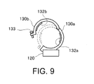
- Fig. 9 is an explanatory diagram exemplifying the first nipping portion 130b and the second nipping portion 130a of a first modified example. Note that, in Fig. 9 , the first nipping portion 130b and the second nipping portion 130a of the finger tip unit 120 are shown, however, the first nipping portion 130b and the second nipping portion 130a may be used for the drive unit 110.
- both the first nipping portion 130b and the second nipping portion 130a are formed to have nearly semi-circular arc shapes, and one end of the first nipping portion 130b is rotatably and axially supported with respect to one end of the second nipping portion 130a. Accordingly, by rotation of the first nipping portion 130b, the state in which the first nipping portion 130b is opened with respect to the second nipping portion 130a (state shown by solid lines in the drawing) and the state in which the first nipping portion 130b is closed with respect to the second nipping portion 130a (state shown by broken lines in the drawing) may be obtained.
- the inside of the second nipping portion 130a is brought into contact with the back of the finger 1 and the first nipping portion 130b is rotated to be closed with respect to the second nipping portion 130a, and then, the first nipping portion 130b is fixed to the second nipping portion 130a using a securement screw 133 provided at the other end of the first nipping portion 130b.
- the finger 1 may be nipped with the first sensor 132b of the first nipping portion 130b pressed against the pad of the finger 1 and the second sensor 132a of the second nipping portion 130a pressed against the back of the finger 1.
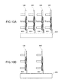
- Figs. 10A and 10B are explanatory diagrams exemplifying a second modified example in which a plurality of finger assist devices 100 are attached to attachment members 300 in parallel.
- the respective finger assist devices 100 are attached via attachment parts 302 to the attachment members 300 in parallel.
- the attachment member 300 is worn on a palm or back of a hand, and thereby, the finger assist device 100 may be worn in an appropriate position with respect to the finger 1. Accordingly, the bending movement of the finger 1 may be appropriately assisted.
- the four finger assist devices 100 are attached to the attachment member 300, and the bending movement of the four fingers 1 of the index finger, the middle finger, the ring finger, and the little finger may be assisted.
- one more finger assist device 100 may be attached to the attachment member 300 so that the bending movement of the thumb may be assisted.
- the finger assist devices 100 may be attached to the attachment member 300 only for the fingers 1 that require assistance.
Landscapes
- Health & Medical Sciences (AREA)
- Life Sciences & Earth Sciences (AREA)
- Veterinary Medicine (AREA)
- Public Health (AREA)
- General Health & Medical Sciences (AREA)
- Animal Behavior & Ethology (AREA)
- Biomedical Technology (AREA)
- Heart & Thoracic Surgery (AREA)
- Engineering & Computer Science (AREA)
- Vascular Medicine (AREA)
- Transplantation (AREA)
- Orthopedic Medicine & Surgery (AREA)
- Oral & Maxillofacial Surgery (AREA)
- Cardiology (AREA)
- Nursing (AREA)
- Epidemiology (AREA)
- Rehabilitation Therapy (AREA)
- Physical Education & Sports Medicine (AREA)
- Pain & Pain Management (AREA)
- Manipulator (AREA)
- Prostheses (AREA)
Abstract
Description
- The present invention relates to a finger assist device.
- Devices for assisting finger movement worn on hands of people with difficulty in bending and spreading of fingers due to accidents and diseases, people with weakened grips, and elderly people with less power due to aging have been proposed (Patent Document 1 (
JP-A-2002-345861 JP-A-2011-115248 - However, it is hard to detect a person's intention to bend or spread a finger, and accordingly, in either of the proposals, there has been a problem of difficulty in appropriate assistance of bending movement or spreading movement of the finger.
- An advantage of some aspects of the invention is to provide a technology that may appropriately assist bending movement or spreading movement of a finger by detecting a person's intention to bend or spread the finger.
- A finger assist device according to an aspect of the invention employs the following configuration. That is, a finger assist device worn on a finger and assisting movement of bending the finger includes a plurality of units rotatably connected in a bending direction in which the finger bends and a spreading direction in which the finger spreads in an opposite direction to the bending direction, suppose that a side facing an object to be grasped by the finger is a pad of the finger and an opposite side of the pad of the finger is a back of the finger, a nipping part provided in each of the plurality of units and nipping the pad of the finger and the back of the finger, at least one of a first sensor that detects a first contact force generated between the nipping part and the pad of the hand finger and a second sensor that detects a second contact force generated between the nipping part and the back of the hand finger provided in the nipping part, a drive part connected to the unit and rotationally driving the unit in the direction in which the finger bends or the direction in which the finger spreads, and a drive force control part that controls a drive force of the drive part for rotationally driving the unit based on the first contact force and the second contact force.
- The finger assist device according to the aspect of the invention assists the movement of the finger by rotationally driving the connected plurality of units in the direction in which the finger bends or the direction in which the finger spreads. Here, the unit is attached to the finger by nipping the finger with the nipping part from the pad and the back of the finger. Note that "finger pad" refers to a side at which the finger faces an object when the finger is bent for grasping the object. Further, "finger back" refers to an opposite side to the finger pad. Further, the drive force is controlled by detecting the contact force between the finger pad and the nipping part (first contact force) and the contact force between the finger back and the nipping part (second contact force). The details will be described later, and, since the intention of a wearer of the finger assist device appears in the first contact force and the second contact force, the drive force of the finger assist device is appropriately controlled according to the wearer's intention in this manner, and thereby, bending movement and spreading movement of the finger may be appropriately assisted.
- In the finger assist device according to the aspect of the invention, in the state in which the unit is rotationally driven in the bending direction of the finger, the drive force may be increased and decreased in the following manner. That is, the drive force may be increased if the first contact force is larger than the second contact force and the drive force may be decreased if the first contact force is smaller than the second contact force.
- The case where the first contact force is larger than the second contact force in the state in which the unit is rotationally driven in the bending direction of the finger is considered as the case where the wearer tends to further bend the finger. In contrast, the case where the first contact force is smaller than the second contact force is considered as the case where the wearer tends to weaken the force for bending the finger. Therefore, the contact forces are detected in the above described manner, and thereby, the drive force may be increased or decreased according to the wearer's intention.
- In the finger assist device according to the aspect of the invention, if the difference between the first contact force and the second contact force when the unit is rotationally driven in the bending direction of the finger is smaller than a predetermined threshold value, the drive force may not be increased or decreased. That is, in the state in which the unit is rotationally driven in the bending direction of the finger, if the first contact force is larger than the second contract force by a first increase-side threshold value or more, the drive force is increased, and if the second contact force is larger than the first contract force by a first decrease-side threshold value or more, the drive force is decreased. Further, in the state in which the unit is rotationally driven in the bending direction of the finger, if the first contact force is larger than the second contract force and an excess amount of the first contact force with respect to the second contact force is less than the first increase-side threshold value, or if the second contact force is larger than the first contact force and an excess amount of the second contact force with respect to the first contact force is less than the first decrease-side threshold value, the drive force may be maintained. Note that the threshold value at the side at which the drive force is increased (first increase-side threshold value) and the threshold value at the side at which the drive force is decreased (first decrease-side threshold value) are sufficient as long as they may be individually set, and the first increase-side threshold value and the first decrease-side threshold value may be set to the same value.
- According to the configuration, increase and decrease of the drive force with increase and decrease of the first contact force and the second contact force by the slight movement of the finger not intended by the wearer (e.g., trembling of the finger) may be avoided. As a result, the bending movement and the spreading movement of the finger may be stably assisted according to the wearer's intention.
- In the finger assist device according to the aspect of the invention, in the state in which the unit is rotationally driven in the spreading direction, the drive force may be increased and decreased in the following manner. That is, the drive force may be decreased if the first contact force is larger than the second contact force and the drive force may be increased if the first contact force is smaller than the second contact force.
- The case where the first contact force is larger than the second contact force in the state in which the unit is rotationally driven in the spreading direction is considered as the case where the wearer tends to weaken the force for spreading the finger. In contrast, the case where the first contact force is smaller than the second contact force is considered as the case where the wearer tends to further spread the finger. Therefore, by controlling the drive force in the above described manner, the drive force may be increased or decreased according to the wearer's intention.
- In the finger assist device according to the aspect of the invention, if the difference between the first contact force and the second contact force when the unit is rotationally driven in the spreading direction is smaller than a predetermined threshold value, the drive force may not be increased or decreased. That is, in the state in which the unit is rotationally driven in the spreading direction, if the second contact force is larger than the first contract force by a second increase-side threshold value or more, the drive force is increased, and if the first contact force is larger than the second contract force by a second decrease-side threshold value or more, the drive force is decreased. Furthermore, in the state in which the unit is rotationally driven in the spreading direction, if the second contact force is larger than the first contract force and an excess amount of the second contact force with respect to the first contact force is less than the second increase-side threshold value, or if the first contact force is larger than the second contact force and an excess amount of the first contact force with respect to the second contact force is less than the second decrease-side threshold value, the drive force may be maintained. Note that the threshold value at the side at which the drive force is increased (second increase-side threshold value) and the threshold value at the side at which the drive force is decreased (second decrease-side threshold value) are sufficient as long as they may be individually set, and the second increase-side threshold value and the second decrease-side threshold value may be set to the same value.
- According to the configuration, increase and decrease of the drive force with increase and decrease of the first contact force and the second contact force by the slight movement of the finger not intended by the wearer (e.g., trembling of the finger) may be avoided. As a result, the bending movement and the spreading movement of the finger may be stably assisted according to the wearer's intention.
- In the finger assist device according to the aspect of the invention, the second increase-side threshold value may be set to be a smaller value than the first increase-side threshold value and the second decrease-side threshold value may be set to be a smaller value than the first decrease-side threshold value.
- Generally, at spreading of the finger, the force of the finger is smaller than that at bending. Therefore, by setting the second increase-side threshold value to be the smaller value than the first increase-side threshold value and the second decrease-side threshold value to be the smaller value than the first decrease-side threshold value, at spreading of the finger, the movement of the finger may be assisted from when the finger is subject to the smaller force than that at bending.
- In the finger assist device according to the aspect of the invention, the first sensor and the second sensor may be provided especially in the nipping part of the unit at the tip end side of the finger among the units. Note that, in this case, the first sensor and the second sensor may be provided in the nipping parts of the other units.
- When the finger is bent or spread, the movement of the finger is larger toward the tip end of the finger. Therefore, by providing the first sensor and the second sensor especially in the nipping part of the unit at the tip end side of the finger among the units, the wearer's intention may be sensitively sensed and the movement of the finger may be appropriately assisted.
- In the finger assist device according to the aspect of the invention, a first nipping portion provided on the finger pad may be formed more deformably than a second nipping portion provided on the finger back.
- According to the configuration, when the wearer grasps an object, a feeling of grasping the object is transmitted to the finger pad of the wearer via the first nipping portion, and a finger assist device that may easily grasp an object may be realized.
- In the finger assist device according to the aspect of the invention, a vibrator formed to contain a piezoelectric material may be used as the drive part for rotationally driving the unit. As the vibrator, a bending vibration-type piezo-actuator may be preferably used.
- According to the configuration, a thinner vibrator enables a thinner finger assist device. Further, the vibrator is pressed against a connecting member for use, and thus, while the connecting member is not rotationally driven, the vibrator functions as a brake for preventing rotation of the connecting member. Accordingly, even when the connecting member is not driven by the vibrator, the finger does not lean back due to the load.
- The invention will be described with reference to the accompanying drawings, wherein like numbers reference like elements.
-
Figs. 1A to 1C are overall views of a finger assist device of an embodiment. -
Figs. 2A to 2C are explanatory diagrams showing a structure of a drive unit of the finger assist device. -
Fig. 3 is a perspective view showing a structure of a piezoelectric motor. -
Figs. 4A to 4C are explanatory diagrams showing an operation principle of the piezoelectric motor. -
Figs. 5A and 5B are explanatory diagrams showing movement of the finger assist device. -
Figs. 6A and 6B are explanatory diagrams showing an operation principle of detecting an intention of a wearer of the finger assist device based on output of a first sensor and a second sensor. -
Fig. 7 is a flowchart of drive force adjustment processing of adjusting a drive force of the piezoelectric motor. -
Figs. 8A and 8B are explanatory diagrams conceptually showing a correspondence relationship for bending movement and a correspondence relationship for spreading movement stored in a memory of a drive control part. -
Fig. 9 is an explanatory diagram exemplifying a first nipping portion and a second nipping portion of a first modified example. -
Figs. 10A and 10B are explanatory diagrams exemplifying a second modified example in which a plurality of finger assist devices are attached to attachment members in parallel. -
Figs. 1A and 1B are explanatory diagrams showing a state in which afinger assist device 100 of an embodiment is worn on a finger 1 (index finger) of a hand of a human.Fig. 1A shows the state seen from a pad of the finger 1, andFig. 1B shows the state seen from a side surface side of the finger 1. Further, thesign 1a shown inFigs. 1A and 1B denotes a nail of the finger 1, thesign 1b denotes a fork of the finger 1, and thesigns 1c denote joints of the finger 1. Note that "finger pad" refers to a side at which the finger 1 faces an object when the finger 1 is bent for grasping the object. Further, "finger back" refers to an opposite side to the finger pad. Note that, in the embodiment, the case where the device is worn on the finger 1 of the hand of the human is explained, however, the device may be worn on a finger of a shoe or a finger of a hand or shoe of an animal, not a human. - As illustrated, the finger assist
device 100 of the embodiment includes a plurality of (two in the illustrated example) series-connecteddrive units 110, and afinger tip unit 120 connected to a tip end. The same twodrive units 110 are used, and, when it is necessary to distinguish the units, they are respectively referred to asdrive units Figs. 1A and 1B . Further, thedrive unit 110 of the embodiment corresponds to "unit" in the invention. - As shown in
Fig. 1A , thedrive unit 110 includes afirst member 111 provided at the side of the finger 1, asecond member 112 provided at the opposite side to the finger 1 with thefirst member 111 in between, arotor 113 having a disc shape and provided between thefirst member 111 and thesecond member 112, apiezoelectric motor 200 that rotates therotor 113, afirst spur gear 114 that rotates with therotor 113, asecond spur gear 115 fitted with thefirst spur gear 114, and connectingscrews 116 that connect thefirst spur gear 114 to thesecond member 112 of theadjacent drive unit 110. Therefore, therespective drive units 110 may be freely attached and detached by fastening and loosening the connecting screws 116. Further, thepiezoelectric motor 200 is connected to a drive control unit 250 that controls the driving direction and the drive force of thepiezoelectric motor 200 by supplying drive signals. Note that thepiezoelectric motor 200 of the embodiment corresponds to "drive part" or "vibrator" in the invention, and the drive control part 250 of the embodiment corresponds to a "drive force control part" in the invention. - Further, a
first nipping portion 130b and asecond nipping portion 130a are provided in each of thefirst member 111 of thedrive unit 110a, thefirst member 111 of thedrive unit 110b, and thefinger tip unit 120, and thefirst nipping portion 130b nips the finger 1 from the pad of the finger 1 and thesecond nipping portion 130a nips the finger 1 from the back of the finger 1. Accordingly, as shown inFigs. 1A and 1B , the finger 1 is nipped by thefirst nipping portions 130b and thesecond nipping portions 130a provided in thedrive units finger tip unit 120, and thereby, the finger assistdevice 100 of the embodiment may be worn on the finger 1. Furthermore, thesecond nipping portion 130a is formed using a non-deformable material including metal or hard resin, and thefirst nipping portion 130b is formed using a deformable material including soft resin. Accordingly, even when grasping an object with the finger assistdevice 100 worn on the finger 1, the wearer may feel a sense of grasping the object with the pad of the finger 1 via thefirst nipping portions 130b. Note that thefirst nipping portion 130b and thesecond nipping portion 130a of the embodiment correspond to "nipping part" in the invention. -
Fig. 1C shows a sectional view of thefinger tip unit 120 cut along A-A. As illustrated, afirst sensor 132b is provided in a position in contact with the pad of the finger 1 in thefirst nipping portion 130b of thefinger tip unit 120. Further, asecond sensor 132a is provided in a position in contact with the back of the finger 1 in thesecond nipping portion 130a of thefinger tip unit 120. Accordingly, when the finger assistdevice 100 of the embodiment is worn on the finger 1, the pad of the finger 1 is in contact with and lightly pressed against thefirst sensor 132b, and the back of the finger 1 is in contact with and lightly pressed against thesecond sensor 132a. - The output from the
first sensor 132b and thesecond sensor 132a is supplied to the drive control part 250. Further, the drive control part 250 drives thepiezoelectric motor 200 based on the output from thefirst sensor 132b and thesecond sensor 132a. This point will be explained in detail later. Note that, in the embodiment, the explanation that thefirst sensor 132b and thesecond sensor 132a are attached only to thefirst nipping portion 130b and thesecond nipping portion 130a of thefinger tip unit 120 is made, however, thefirst sensor 132b and thesecond sensor 132a may be attached to thefirst nipping portions 130b and thesecond nipping portions 130a of thedrive units -
Figs. 2A to 2C are explanatory diagrams showing a detailed structure of thedrive unit 110. Note that, inFigs. 2A to 2C , the illustration ofattachment portions 102, 104 is omitted.Fig. 2A is a front view of thedrive unit 110 seen from the opposite side to the side worn on the finger 1 (the side of the second member 112),Fig. 2B is a sectional view of thedrive unit 110 in the center position, andFig. 2C is a rear view of thedrive unit 110 seen from the side worn on the finger 1 (the side of the first member 111). - In the
first member 111,bosses 111b having cylindrical shapes are projected in two locations and thepiezoelectric motor 200 is screwed on the top surfaces of thebosses 111b. The structure of thepiezoelectric motor 200 will be described later. Further, the disc-shapedrotor 113 is attached between thefirst member 111 and thesecond member 112, and thefirst spur gear 114 is coaxially attached to therotor 113 and integrally rotates with therotor 113. Furthermore, thesecond spur gear 115 is fitted with thefirst spur gear 114. Therefore, when therotor 113 is rotated using thepiezoelectric motor 200, thefirst spur gear 114 rotates with therotor 113 and thesecond spur gear 115 rotates. Thesecond spur gear 115 has the larger number of teeth than that of thefirst spur gear 114. Accordingly, the rotation of thefirst spur gear 114 is decelerated (therefore, energized) and transmitted to thesecond spur gear 115. -
Fig. 3 is a perspective view showing the structure of thepiezoelectric motor 200. As illustrated, thepiezoelectric motor 200 has a multilayered structure in which ashim plate 210 formed by a metal flat plate is sandwiched and bonded between two piezoelectric devices (frontpiezoelectric device 220, rear piezoelectric device 221) formed in plate-like shapes and containing a piezoelectric material. Note that, as below, the longitudinal direction of thepiezoelectric motor 200 will be referred to as "X-direction". Further, as shown in the drawing, the lateral direction of thepiezoelectric motor 200 orthogonal to the X-direction will be referred to as "Y-direction", and the thickness direction of thepiezoelectric motor 200 orthogonal to the X-direction and the Y-direction will be referred to as "Z-direction". -
Front electrodes 222 for applying voltages to the frontpiezoelectric device 220 are provided on the surface (upper surface) opposite to the surface of the frontpiezoelectric device 220 in contact with theshim plate 210. As shown inFig. 3 , the four rectangularfront electrodes 222 are provided to split the upper surface of the frontpiezoelectric device 220 into four in a lattice shape. Further, though not illustrated, similarly, four rectangularrear electrodes 223 are provided on the surface (lower surface) opposite to the surface of the rearpiezoelectric device 221 in contact with theshim plate 210 to split the lower surface into four in a lattice shape. Furthermore, the metal shim plate - 210 has a role not only to reinforce the piezoelectric devices (front
piezoelectric device 220, rear piezoelectric device 221) but also as a common electrode for applying voltages to the frontpiezoelectric device 220 and the rearpiezoelectric device 221, and is grounded. - A
convex portion 212 is provided at the end in the longitudinal direction (X-direction) of thepiezoelectric motor 200. Further, a pair ofsupport portions 214 for supporting thepiezoelectric motor 200 to be urged toward the side at which theconvex portion 212 is provided are provided on both side surfaces facing in the lateral direction (Y-direction) of thepiezoelectric motor 200. Theseconvex portion 212 and thesupport portions 214 are formed integrally with theshim plate 210. -
Figs. 4A to 4C are explanatory diagrams showing an operation principle of thepiezoelectric motor 200. Thepiezoelectric motor 200 operates by elliptic motion of theconvex portion 212 of thepiezoelectric motor 200 when voltages are applied to thefront electrodes 222 and therear electrodes 223 of thepiezoelectric motor 200 with a constant period. Theconvex portion 212 of thepiezoelectric motor 200 makes elliptic motion for the following reason. Note that thefront electrodes 222 provided on the frontpiezoelectric device 220 and therear electrodes 223 provided on the rearpiezoelectric device 221 are plane-symmetric with respect to the X-Y plane and basically the same and, here, the explanation will be made by taking thefront electrodes 222 as examples. - First, as is well known, the piezoelectric devices containing the piezoelectric material (front
piezoelectric device 220, rear piezoelectric device 221) have properties of expanding when positive voltages are applied. Therefore, as shown inFig. 4A , when application of positive voltages to all of the fourfront electrodes 222 and non-application of the voltages are repeated at specific frequencies, the piezoelectric motor 200 (front electrodes 222) may produce a kind of resonance phenomenon of expanding and contracting in the longitudinal direction (X-direction). The movement of thepiezoelectric motor 200 repeating expanding and contracting in the longitudinal direction (X-direction) is called "longitudinal vibration", and the directions in which thepiezoelectric motor 200 expands and contracts (±X-directions in the drawing) are called "stretching directions". - Further, as shown in
Fig. 4B or 4C , with the twofront electrodes 222 diagonally located to each other as sets (a set of thefront electrode 222a and thefront electrode 222d or a set of thefront electrode 222b and thefront electrode 222c), when voltages at specific frequencies are applied, a kind of resonance phenomenon that the end of the piezoelectric motor 200 (front piezoelectric device 220) in the longitudinal direction (X-direction) (the part provided with the convex portion 212) oscillates in the lateral direction (Y-direction) on the drawing may be produced. For example, as shown inFig. 4B , when the positive voltages are applied to the set of thefront electrode 222a and thefront electrode 222d with a constant period, the end of thepiezoelectric motor 200 in the longitudinal direction repeats movement of moving to the right. Furthermore, as shown inFig. 4C , when the positive voltages are applied to the set of thefront electrode 222b and thefront electrode 222c with a constant period, the end of thepiezoelectric motor 200 in the longitudinal direction repeats movement of moving to the left. The movement of thepiezoelectric motor 200 is called "bending vibration". As below, the directions in which thepiezoelectric motor 200 bends and vibrates (±Y-directions in the drawing) are called "bending directions". - Further, by appropriate selection of the properties of the front
piezoelectric device 220 and the dimensions (width W, length L, thickness T) of the frontpiezoelectric device 220, resonance in "bending vibration" may induce the resonance in "longitudinal vibration" at the same time. As a result, when the voltages are applied to the set of thefront electrode 222a and thefront electrode 222d in the form shown inFig. 4B , the end of the piezoelectric motor 200 (the part provided with the convex portion 212) makes movement of describing an ellipse (elliptic motion) clockwise on the drawing. Furthermore, when the voltages are applied to the set of thefront electrode 222b and thefront electrode 222c in the form shown inFig. 4C , the end of thepiezoelectric motor 200 makes elliptic motion counterclockwise on the drawing. The completely same as thepiezoelectric device 220 applies the rearpiezoelectric device 221. - The
piezoelectric motor 200 drives a driven member using the elliptical motion. That is, the elliptical motion is generated with theconvex portion 212 of thepiezoelectric motor 200 pressed against the driven member. Then, theconvex portion 212 repeats the movement of moving from left to right (or from right to left) while being pressed against the driven member when thepiezoelectric motor 200 expands, and returning to the original position while being apart from the driven member when thepiezoelectric motor 200 contracts. As a result, the driven member is driven in one direction by the frictional force from theconvex portion 212. - The
piezoelectric motor 200 mounted on thedrive unit 110 of the embodiment is set with theconvex portion 212 pressed against the rotor 113 (seeFigs. 2A to 2C ). Accordingly, when thepiezoelectric motor 200 is driven, therotor 113 and therotor 113 rotate and the rotation is transmitted to thesecond spur gear 115. Further, as shown inFigs. 1A and 1B , the adjacent drive unit 110 (or finger tip unit 120) is connected to thesecond spur gear 115. Accordingly, thepiezoelectric motor 200 is driven, and thereby, thedrive unit 110a and thedrive unit 110b or thedrive unit 110b and thefinger tip unit 120 may be bent or spread. -
Figs. 5A and 5B are explanatory diagrams showing movement of the finger assistdevice 100 of the embodiment. For example, as shown inFig. 5A , when thepiezoelectric motor 200 of thedrive unit 110a is driven to rotate therotor 113 of thedrive unit 110a clockwise on the paper surface, thedrive unit 110b moves to bend the finger with respect to thedrive unit 110a. Similarly, when thepiezoelectric motor 200 of thedrive unit 110b is driven to rotate therotor 113 of thedrive unit 110b clockwise on the paper surface, thefinger tip unit 120 moves to bend with respect to thedrive unit 110b. As a result, as shown by a hollow arrow inFig. 5A , the finger assistdevice 100 bends. - As shown in
Fig. 5B , when thepiezoelectric motors 200 of thedrive unit 110a and thedrive unit 110b are driven in the opposite direction to drive therotor 113 counterclockwise on the paper surface, as shown by a hollow arrow in the drawing, the finger assistdevice 100 may be spread. - As described above, the finger assist
device 100 of the embodiment may assist the movement of the finger 1 bending or spreading by being worn on the side surface of the finger 1 and driving thepiezoelectric motors 200. However, in order to appropriately assist the movement of the finger 1 by the finger assistdevice 100, it is important to appropriately detect the human' s (wearer's) intention that the human wearing the finger assistdevice 100 on the finger 1 tends to bend or spread the finger 1. Furthermore, even when the wearer bends the finger 1 and the movement is assisted by the finger assistdevice 100, it is important to detect that the human feels the assistance force weaker or stronger. When the wearer spreads the finger 1, similarly, it is important to detect that the human feels the assistance force of the finger assistdevice 100 for the finger 1 weaker or stronger. Accordingly, the finger assistdevice 100 of the embodiment detects the wearer' s intention using the output of thefirst sensor 132b attached to thefirst nipping portion 130b and thesecond sensor 132a attached to thesecond nipping portion 130a. -
Figs. 6A and 6B are explanatory diagrams showing a principle of detecting the wearer's intention of the finger assistdevice 100 of the embodiment based on output of thefirst sensor 132b and thesecond sensor 132a. Note that thesign 1a shown inFigs. 6A and 6B denotes a nail of the finger 1, thesign 1b denotes a fork of the finger 1, and thesigns 1c denote joints of the finger 1. As has been described usingFigs. 1A and 1B , when the finger assistdevice 100 is worn on the finger 1, thefirst nipping portion 130b nips the finger 1 from the pad of the finger 1 and thesecond nipping portion 130a nips the finger 1 from the back of the finger 1 while being lightly pressed against the finger 1. Accordingly, contact forces respectively act between thefirst sensor 132b provided in thefirst nipping portion 130b and the finger 1 and between thesecond sensor 132a provided in thesecond nipping portion 130a and the finger 1. Note that, as below, the contact force acting between thefirst sensor 132b and the finger 1 is referred to as "first contact force" and the contact force acting between thesecond sensor 132a and the finger 1 is referred to as "second contact force". - Here, as shown in
Fig. 6A , the case where the wearer tends to bend the finger 1 is considered. When the operator is bending the finger 1 from the state in which the finger 1 is stationary, the finger 1 of the wearer presses thefirst nipping portion 130b, and thereby, the first contact force F1 detected by thefirst sensor 132b increases. Further, the finger 1 of the wearer is separating from thesecond nipping portion 130a, and thereby, the second contact force F2 detected by thesecond sensor 132a decreases. Alternatively, if the wearer tends to make the bending force stronger when the finger 1 is bending, the finger 1 of the wearer also presses thefirst nipping portion 130b. Accordingly, the first contact force F1 detected by thefirst sensor 132b increases and the second contact force F2 detected by thesecond sensor 132a decreases. - On the other hand, if the wearer tends to make the bending force weaker when the finger 1 is bending, the wearer weakens the bending force of the finger 1, and, as a result, the movement of the
finger tip unit 120 and thedrive unit 110 of the finger assistdevice 100 overtakes the movement of the finger 1 of the wearer. Accordingly, the finger 1 of the wearer presses thesecond nipping portion 130a, and thereby, the second contact force F2 detected by thesecond sensor 132a increases and the first contact force F1 detected by thefirst sensor 132b decreases. - As is clear from the above description, at the bending movement of the finger 1 (including the halt state before bending), when the first contact force F1 detected by the
first sensor 132b is larger than the second contact force F2 detected by thesecond sensor 132a, the finger assistdevice 100 may increase the force assisting the finger 1 in the bending direction. On the other hand, it is known that, when the first contact force F1 is smaller than the second contact force F2, the finger assistdevice 100 may decrease the force assisting the finger 1 in the bending direction. - Next, as shown in
Fig. 6B , the case where the wearer tends to spread the finger 1 is considered. When the operator is spreading the finger 1 from the state in which the finger 1 is stationary, the finger 1 of the wearer presses thesecond nipping portion 130a, and thereby, the second contact force F2 detected by thesecond sensor 132a increases. Further, the finger 1 of the wearer is separating from thefirst nipping portion 130b, and thereby, the first contact force F1 detected by thefirst sensor 132b decreases. Alternatively, if the wearer tends to make the spreading force stronger when the finger 1 is spreading, the finger 1 of the wearer also presses thesecond nipping portion 130a. Accordingly, the second contact force F2 detected by thesecond sensor 132a increases and the first contact force F1 detected by thefirst sensor 132b decreases. - On the other hand, if the wearer tends to make the spreading force weaker when the finger 1 is spreading, the wearer weakens the spreading force of the finger 1, and, as a result, the movement of the
finger tip unit 120 and thedrive unit 110 of the finger assistdevice 100 overtakes the movement of the finger 1 of the wearer. Accordingly, the finger 1 of the wearer presses thefirst nipping portion 130b, and thereby, the first contact force F1 detected by thefirst sensor 132b increases and the second contact force F2 detected by thesecond sensor 132a decreases. - As is clear from the above description, at the spreading movement of the finger 1 (including the halt state before spreading), when the second contact force F2 detected by the
second sensor 132a is larger than the first contact force F1 detected by thefirst sensor 132b, the finger assistdevice 100 may increase the force assisting the finger 1 in the spreading direction. On the other hand, it is known that, when the second contact force F2 is smaller than the first contact force F1, the finger assistdevice 100 may decrease the force assisting the finger 1 in the spreading direction. - In this manner, by comparison between the first contact force F1 detected by the
first sensor 132b and the second contact force F2 detected by thesecond sensor 132a, the drive force of thepiezoelectric motor 200 can be increased and decreased according to the intention of the wearer of the finger assistdevice 100. Accordingly, the bending movement or spreading movement of the finger 1 may be appropriately assisted using the finger assistdevice 100. - As above, the explanation has been made while focusing attention on the principle that enables the assist operation according to the wearer's intention by comparison between the first contact force F1 and the second contact force F2. In the case where the principle is applied to the actual control, as the difference between the first contact force F1 and the second contact force F2 is larger, the drive force of the
piezoelectric motor 200 may be changed more significantly. Further, if the difference between the first contact force F1 and the second contact force F2 is equal to or less than a predetermined threshold value, the drive force of thepiezoelectric motor 200 in this regard may be maintained. -
Fig. 7 is a flowchart of drive force adjustment processing executed by the finger assistdevice 100 of the embodiment for adjustment of the drive force of thepiezoelectric motor 200 according the wearer's intention. The processing is executed while the drive control part 250 of the finger assistdevice 100 is driving thepiezoelectric motor 200. - As illustrated, in the drive force adjustment processing, first, the first contact force F1 detected by the
first sensor 132b and the second contact force F2 detected by thesecond sensor 132a are acquired (S100), and the second contact force F2 is subtracted from the first contact force F1 (S102). Subsequently, the drive control part 250 determines whether or not thepiezoelectric motor 200 is being driven in the bending direction of the finger (seeFig. 5A ) (S104). The driving direction of thepiezoelectric motor 200 is controlled by the drive control part 250, and thereby, the drive control part 250 may easily determine whether or not the motor is currently being driven in the bending direction of the finger. As a result, if the part determines that the motor is being driven in the bending direction of the finger (S104: yes), the part determines an amount of adjustment of the drive force with reference to a correspondence relationship for bending movement (S106). Here, "correspondence relationship" refers to a correspondence relationship between the subtraction value (= first contact force F1 - second contact force F2) and the amount of adjustment of the drive force of thepiezoelectric motor 200. In the memory (not shown) of the drive control part 250 of the embodiment, the correspondence relationship for bending movement and a correspondence relationship for spreading movement are stored in advance. -
Figs. 8A and 8B are explanatory diagrams conceptually showing the correspondence relationship for bending movement and the correspondence relationship for spreading movement stored in the memory of the drive control part 250.Fig. 8A shows the correspondence relationship for bending movement andFig. 8B shows the correspondence relationship for spreading movement. In the correspondence relationship for bending movement shown inFig. 8A , if the first contact force F1 is larger than the second contact force F2 and an excess amount of the first contact force F1 with respect to the second contact force F2 is less than a first increase-side threshold value th1u or if the second contact force F2 is larger than the first contact force F1 and an excess amount of the second contact force F2 with respect to the first contact force F1 is less than a first decrease-side threshold value th1d, the amount of adjustment of the drive force is set to "0". Accordingly, in either of the cases, the drive force of thepiezoelectric motor 200 is maintained without change. Note that the first increase-side threshold value th1u and the first decrease-side threshold value th1d may be set to the same value or different values. - Further, if the first contact force F1 is larger than the second contact force F2, as the subtraction value obtained by subtraction of the second contact force F2 from the first contact force F1 is larger than the first increase-side threshold value th1u, the amount of adjustment of the drive force is set to a larger positive value. Accordingly, during the bending movement, if the first contact force F1 is larger than the second contact force F2 and the subtraction value obtained by subtraction of the second contact force F2 from the first contact force F1 is larger by the first increase-side threshold value th1u or more, as the subtraction value is larger, the drive force is adjusted to increase more significantly.
- On the other hand, if the first contact force F1 is smaller than the second contact force F2, as the subtraction value obtained by subtraction of the first contact force F1 from the second contact force F2 is larger than the first decrease-side threshold value th1d, the amount of adjustment of the drive force is set to a negative value having a larger absolute value. Accordingly, during the bending movement, if the second contact force F2 is larger than the first contact force F1 and the subtraction value obtained by subtraction of the first contact force F1 from the second contact force F2 is larger by the first decrease-side threshold value th1d or more, as the subtraction value is larger, the drive force is adjusted to decrease more significantly.
- At S106 in
Fig. 7 , the control part determines the amount of adjustment of the drive force of thepiezoelectric motor 200 based on the subtraction value obtained by subtraction of the second contact force F2 from the first contact force F1 as described above. Then, the part adjusts the drive force of thepiezoelectric motor 200 using the determined amount of adjustment (S108), then, returns to the head of the processing, and acquires the first contact force F1 and the second contact force F2 again (S100) and performs the subsequent above described series of processing. - On the other hand, if the control part determines that the finger assist
device 100 is not in the bending movement at S104 (S104: no), in turn, the part determines whether or not the device is in spreading movement (S110). As a result, if the part determines that the device is in spreading movement (S110: yes), the part determines an amount of adjustment of the drive force with reference to the correspondence relationship for spreading movement (seeFig. 8B ) (S112). As shown inFig. 8B , in the correspondence relationship for spreading movement, if the first contact force F1 is larger than the second contact force F2 and an excess amount of the first contact force F1 with respect to the second contact force F2 is less than a second decrease-side threshold value th2d or if the second contact force F2 is larger than the first contact force F1 and an excess amount of the second contact force F2 with respect to the first contact force F1 is less than a second increase-side threshold value th2u, the amount of adjustment of the drive force is set to "0". Accordingly, in either of the cases, the drive force of thepiezoelectric motor 200 is maintained without change. Note that the second decrease-side threshold value th2d and the second increase-side threshold value th2u may be set to the same value or different values. - Further, the second increase-side threshold value th2u used at the spreading movement is set to be a smaller value than that of the first increase-side threshold value th1u used at the bending movement, and similarly, the second decrease-side threshold value th2d used at the spreading movement is set to be a smaller value than that of the first decrease-side threshold value th1d used at the bending movement. This is because the force of the first finger 1 is weaker at spreading than that at bending and the finger assist
device 100 may assist the finger 1 from when the force of the first finger 1 is smaller. - Furthermore, if the first contact force F1 is larger than the second contact force F2, as the subtraction value obtained by subtraction of the second contact force F2 from the first contact force F1 is larger than the second decrease-side threshold value th2d, the amount of adjustment of the drive force is set to a negative value having a larger absolute value. Accordingly, during the spreading movement, if the first contact force F1 is larger than the second contact force F2 and the subtraction value obtained by subtraction of the second contact force F2 from the first contact force F1 is larger by the second decrease-side threshold value th2d or more, as the subtraction value is larger, the drive force is adjusted to decrease more significantly.
- On the other hand, if the first contact force F1 is smaller than the second contact force F2, as the subtraction value obtained by subtraction of the first contact force F1 from the second contact force F2 is larger than the second increase-side threshold value th2u, the amount of adjustment of the drive force is set to a larger positive value. Accordingly, during the spreading movement, if the second contact force F2 is larger than the first contact force F1 and the subtraction value obtained by subtraction of the first contact force F1 from the second contact force F2 is larger by the second increase-side threshold value th2u or more, as the subtraction value is larger, the drive force is adjusted to increase more significantly.
- At S112 in
Fig. 7 , the control part determines the amount of adjustment of the drive force of thepiezoelectric motor 200 based on the subtraction value obtained by subtraction of the second contact force F2 from the first contact force F1 as described above. Then, the part adjusts the drive force of thepiezoelectric motor 200 using the determined amount of adjustment (S114), then, returns to the head of the processing, and acquires the first contact force F1 and the second contact force F2 again (S100) and performs the subsequent above described series of processing. Further, if the part determines that the device is not in the spreading movement at S110 (S110, no), the part directly returns to the head, and acquires the first contact force F1 and the second contact force F2 again (S100) and continues the subsequent above described series of processing. - The
finger assist device 100 of the embodiment adjusts the drive force of thepiezoelectric motor 200 based on the first contact force F1 detected by thefirst sensor 132b and the second contact force F2 detected by thesecond sensor 132a. Since the intention of the wearer of the finger assistdevice 100 appears in the value of the difference between the first contact force F1 and the second contact force F2, the bending movement and the spreading movement of the finger 1 may be appropriately assisted using the finger assistdevice 100 according to the wearer's intention. - There are several modified examples of the finger assist
device 100 of the embodiment. As below, these modified examples will be briefly explained with attention focused on the differences from the embodiment. Note that, in the following modified examples, the parts in common with the embodiment have the same signs and their detailed explanation will be omitted. - In the above described embodiment, the explanation that the
first nipping portion 130b on the pad of the finger 1 is formed using the more deformable material than that of thesecond nipping portion 130a on the back of the finger 1 has been made (seeFig. 1C ). However, thefirst nipping portion 130b may be formed using a non-deformable material including metal or hard resin like thesecond nipping portion 130a. -
Fig. 9 is an explanatory diagram exemplifying thefirst nipping portion 130b and thesecond nipping portion 130a of a first modified example. Note that, inFig. 9 , thefirst nipping portion 130b and thesecond nipping portion 130a of thefinger tip unit 120 are shown, however, thefirst nipping portion 130b and thesecond nipping portion 130a may be used for thedrive unit 110. - In the illustrated first modified example, both the
first nipping portion 130b and thesecond nipping portion 130a are formed to have nearly semi-circular arc shapes, and one end of thefirst nipping portion 130b is rotatably and axially supported with respect to one end of thesecond nipping portion 130a. Accordingly, by rotation of thefirst nipping portion 130b, the state in which thefirst nipping portion 130b is opened with respect to thesecond nipping portion 130a (state shown by solid lines in the drawing) and the state in which thefirst nipping portion 130b is closed with respect to thesecond nipping portion 130a (state shown by broken lines in the drawing) may be obtained. Further, while thefirst nipping portion 130b is opened, the inside of thesecond nipping portion 130a is brought into contact with the back of the finger 1 and thefirst nipping portion 130b is rotated to be closed with respect to thesecond nipping portion 130a, and then, thefirst nipping portion 130b is fixed to thesecond nipping portion 130a using asecurement screw 133 provided at the other end of thefirst nipping portion 130b. In this manner, the finger 1 may be nipped with thefirst sensor 132b of thefirst nipping portion 130b pressed against the pad of the finger 1 and thesecond sensor 132a of thesecond nipping portion 130a pressed against the back of the finger 1. -
Figs. 10A and 10B are explanatory diagrams exemplifying a second modified example in which a plurality of finger assistdevices 100 are attached toattachment members 300 in parallel. In the second modified example, the respective finger assistdevices 100 are attached viaattachment parts 302 to theattachment members 300 in parallel. In the second modified example, theattachment member 300 is worn on a palm or back of a hand, and thereby, the finger assistdevice 100 may be worn in an appropriate position with respect to the finger 1. Accordingly, the bending movement of the finger 1 may be appropriately assisted. - Note that, in the example shown in
Fig. 10A , the four finger assistdevices 100 are attached to theattachment member 300, and the bending movement of the four fingers 1 of the index finger, the middle finger, the ring finger, and the little finger may be assisted. Obviously, one more finger assistdevice 100 may be attached to theattachment member 300 so that the bending movement of the thumb may be assisted. Further, as exemplified inFig. 10B , the finger assistdevices 100 may be attached to theattachment member 300 only for the fingers 1 that require assistance. - The
finger assist devices 100 of the embodiment and the modified examples have been explained, however, the invention is not limited to the above embodiment or modified examples, but may be implemented in various forms without departing from the scope thereof.
Claims (15)
- A finger assist device (100) assisting movement of a finger comprising:a nipping part that nips the finger for wearing;a plurality of units (110) rotatably connected in a bending direction in which the finger bends and a spreading direction in which the finger spreads in an opposite direction to the bending direction;a sensor provided in the nipping part and detecting a contact force generated between the nipping part and the finger;a drive part (200) connected to the unit (110) and driving the unit; anda drive force control part (250) that controls a drive force of the drive part in response to the contact force detected by the sensor.
- The finger assist device (100) according to claim 1, wherein, a side facing an object to be grasped by the finger being a pad of the finger and an opposite side of the pad of the finger being a back of the finger,
the sensor includes a first sensor (312b) that detects a first contact force generated between the nipping part and the pad of the finger and a second sensor (132a) that detects a second contact force generated between the nipping part and the back of the finger, and
the drive force control part (250) increases the drive force for rotationally driving the unit in the bending direction of the finger if the first contact force is larger than the second contact force, and decreases the drive force for rotationally driving the unit in the bending direction of the finger if the first contact force is smaller than the second contact force. - The finger assist device (100) according to claim 2, wherein the drive force control part (250) increases the drive force for rotationally driving the unit in the bending direction of the finger if the first contact force is larger than the second contact force by a predetermined first increase-side threshold value or more, and decreases the drive force for rotationally driving the unit in the bending direction of the finger if the second contact force is larger than the first contact force by a first decrease-side threshold value, and
the drive force control part (250) maintains the drive force for rotationally driving the unit in the bending direction of the finger if the first contact force is larger than the second contact force and an excess amount of the first contact force with respect to the second contact force is less than the first increase-side threshold value or the second contact force is larger than the first contact force and an excess amount of the second contact force with respect to the first contact force is less than the first decrease-side threshold value. - The finger assist device (100) according to claim 2 or 3, wherein the drive force control part (250) decreases the drive force for rotationally driving the unit in the spreading direction if the first contact force is larger than the second contact force, and increases the drive force for rotationally driving the unit in the spreading direction if the second contact force is larger than the first contact force.
- The finger assist device (100) according to claim 4, wherein the drive force control part (250) decreases the drive force for rotationally driving the unit in the spreading direction if the first contact force is larger than the second contact force by a predetermined second decrease-side threshold value or more, and increases the drive force for rotationally driving the unit in the spreading direction if the second contact force is larger than the first contact force by a second increase-side threshold value, and
the drive force control part (250) maintains the drive force for rotationally driving the unit in the spreading direction if the first contact force is larger than the second contact force and an excess amount of the first contact force with respect to the second contact force is less than the second decrease-side threshold value, or the second contact force is larger than the first contact force and an excess amount of the second contact force with respect to the first contact force is less than the second increase-side threshold value. - The finger assist device (100) according to claim 5, wherein the second increase-side threshold value is set to a value smaller than the first increase-side threshold value, and
the second decrease-side threshold value is set to a value smaller than the first decrease-side threshold value. - The finger assist device according to one of the preceding claims, wherein the first sensor (132b) and the second sensor (132a) are provided in the nipping part of the unit at a tip end side.
- The finger assist device according to one of the preceding claims, wherein the nipping part includes a first nipping portion provided on the pad of the finger and a second nipping portion provided on the back of the finger, and
the first nipping portion is formed to be easily deformable than the second nipping portion. - The finger assist device according to one of the preceding claims, wherein the drive part is a vibrator formed to contain a piezoelectric material.
- Method for assisting the movement of a finger with a finger assist device, the finger assist device comprising:a nipping part that nips the finger for wearing;a plurality of units rotatably connected in a bending direction in which the finger bends and a spreading direction in which the finger spreads in an opposite direction to the bending direction;a sensor provided in the nipping part and detecting a contact force generated between the nipping part and the finger;a drive part connected to the unit and driving the unit;
anda drive force control part that controls a drive force of the drive part in response to the contact force detected by the sensor. - Method according to claim 10, wherein, a side facing an object to be grasped by the finger being a pad of the finger and an opposite side of the pad of the finger being a back of the finger,
the sensor includes a first sensor that detects a first contact force generated between the nipping part and the pad of the finger and a second sensor that detects a second contact force generated between the nipping part and the back of the finger, and
the drive force control part increases the drive force for rotationally driving the unit in the bending direction of the finger if the first contact force is larger than the second contact force, and decreases the drive force for rotationally driving the unit in the bending direction of the finger if the first contact force is smaller than the second contact force. - Method according to claim 11, wherein the drive force control part increases the drive force for rotationally driving the unit in the bending direction of the finger if the first contact force is larger than the second contact force by a predetermined first increase-side threshold value or more, and decreases the drive force for rotationally driving the unit in the bending direction of the finger if the second contact force is larger than the first contact force by a first decrease-side threshold value, and
the drive force control part maintains the drive force for rotationally driving the unit in the bending direction of the finger if the first contact force is larger than the second contact force and an excess amount of the first contact force with respect to the second contact force is less than the first increase-side threshold value or the second contact force is larger than the first contact force and an excess amount of the second contact force with respect to the first contact force is less than the first decrease-side threshold value. - Method according to claim 11 or 12, wherein the drive force control part decreases the drive force for rotationally driving the unit in the spreading direction if the first contact force is larger than the second contact force, and increases the drive force for rotationally driving the unit in the spreading direction if the second contact force is larger than the first contact force.
- Method according to claim 13, wherein the drive force control part decreases the drive force for rotationally driving the unit in the spreading direction if the first contact force is larger than the second contact force by a predetermined second decrease-side threshold value or more, and increases the drive force for rotationally driving the unit in the spreading direction if the second contact force is larger than the first contact force by a second increase-side threshold value, and
the drive force control part maintains the drive force for rotationally driving the unit in the spreading direction if the first contact force is larger than the second contact force and an excess amount of the first contact force with respect to the second contact force is less than the second decrease-side threshold value, or the second contact force is larger than the first contact force and an excess amount of the second contact force with respect to the first contact force is less than the second increase-side threshold value. - Method according to claim 14, wherein the second increase-side threshold value is set to a value smaller than the first increase-side threshold value, and
the second decrease-side threshold value is set to a value smaller than the first decrease-side threshold value.
Applications Claiming Priority (1)
| Application Number | Priority Date | Filing Date | Title |
|---|---|---|---|
| JP2013061543A JP2014184027A (en) | 2013-03-25 | 2013-03-25 | Finger assist device |
Publications (2)
| Publication Number | Publication Date |
|---|---|
| EP2783660A1 true EP2783660A1 (en) | 2014-10-01 |
| EP2783660B1 EP2783660B1 (en) | 2018-04-25 |
Family
ID=50336206
Family Applications (1)
| Application Number | Title | Priority Date | Filing Date |
|---|---|---|---|
| EP14161083.2A Active EP2783660B1 (en) | 2013-03-25 | 2014-03-21 | Finger assisting device |
Country Status (4)
| Country | Link |
|---|---|
| US (1) | US9636270B2 (en) |
| EP (1) | EP2783660B1 (en) |
| JP (1) | JP2014184027A (en) |
| CN (1) | CN104068989B (en) |
Cited By (2)
| Publication number | Priority date | Publication date | Assignee | Title |
|---|---|---|---|---|
| CN106236504A (en) * | 2016-08-26 | 2016-12-21 | 南昌大学 | A kind of finger rehabilitation device being equipped on rehabilitation wheelchair |
| WO2023224534A1 (en) * | 2022-05-16 | 2023-11-23 | Bioservo Technologies Ab | A strengthening glove, a control system, and methods for controlling a strengthening glove |
Families Citing this family (30)
| Publication number | Priority date | Publication date | Assignee | Title |
|---|---|---|---|---|
| JP6108551B2 (en) * | 2013-10-28 | 2017-04-05 | 俊道 妻木 | Operation assistance device |
| GB201403265D0 (en) | 2014-02-25 | 2014-04-09 | Touch Emas Ltd | Prosthetic digit for use with touchscreen devices |
| JP6269171B2 (en) | 2014-03-05 | 2018-01-31 | セイコーエプソン株式会社 | Finger joint drive device |
| CN105267007B (en) * | 2014-05-29 | 2019-03-08 | 精工爱普生株式会社 | Driving device and driving method thereof |
| KR102284822B1 (en) * | 2014-10-22 | 2021-08-02 | 삼성전자주식회사 | A supporting module, a motion assist apparatus comprising thereof and a control method of a motion assist apparatus |
| JP2016082835A (en) * | 2014-10-22 | 2016-05-16 | セイコーエプソン株式会社 | Piezoelectric drive device, finger assist device, and robot |
| JP2016083000A (en) * | 2014-10-23 | 2016-05-19 | セイコーエプソン株式会社 | Driving device, finger joint driving device, and driving method |
| CN105902367B (en) | 2015-02-19 | 2020-02-07 | 松下知识产权经营株式会社 | Assist garment and control method for control unit of assist garment |
| CN105902363B (en) | 2015-02-19 | 2020-02-07 | 松下知识产权经营株式会社 | Assist garment and control method for control unit of assist garment |
| WO2016174083A1 (en) * | 2015-04-29 | 2016-11-03 | Bioservo Technologies Aktiebolag | A control system for a strengthening glove |
| GB2537898B (en) | 2015-04-30 | 2018-02-21 | Hy5Pro As | Palm unit for artificial hand |
| GB2537899B (en) * | 2015-04-30 | 2018-02-21 | Hy5Pro As | Control of digits for artificial hand |
| CN104799808B (en) * | 2015-04-30 | 2017-05-24 | 广州达安临床检验中心有限公司 | Auxiliary stress mechanism and checking device comprising same |
| BR112018016609B1 (en) * | 2016-02-15 | 2023-01-24 | Lime Medical Gmbh | THERAPY DEVICE FOR PERFORMING A SUSTAINED, PASSIVE AND/OR ACTIVELY ASSISTED MOVEMENT OF THE FINGERS AND THUMB OF A PATIENT'S HAND |
| CN105902364A (en) * | 2016-04-01 | 2016-08-31 | 北京所乐思国际商务有限公司 | Joint movement auxiliary device easy to wear and wearing method |
| US11036293B2 (en) * | 2017-12-07 | 2021-06-15 | Flex Ltd. | Method for using fingers to interact with a smart glove worn on a hand |
| US10973660B2 (en) | 2017-12-15 | 2021-04-13 | Touch Bionics Limited | Powered prosthetic thumb |
| WO2019187546A1 (en) * | 2018-03-27 | 2019-10-03 | ソニー株式会社 | Control device, control method, and program |
| WO2020147913A2 (en) * | 2019-01-16 | 2020-07-23 | باهى احمد محمد كامل احمد، | Exoskeleton for motor rehabilitation of the hand and wrist |
| EP4403142B1 (en) | 2019-04-10 | 2025-06-25 | Touch Bionics Limited | Prosthetic digit with articulating links |
| DE102019112051B4 (en) | 2019-05-08 | 2021-01-28 | Universitätsmedizin Der Johannes Gutenberg-Universität Mainz | Length adjustment device for a finger movement splint, length adjustable finger movement splint and therapy device with at least one such length adjustable finger movement splint as well as a method for length adjustment |
| DE102019112049B4 (en) | 2019-05-08 | 2021-01-28 | Universitätsmedizin Der Johannes Gutenberg-Universität Mainz | Finger movement splint for carrying out a continuous, passive and / or actively assisted movement of a finger and / or a thumb of a patient, as well as a therapy device comprising such a finger movement splint |
| JPWO2021014668A1 (en) * | 2019-07-19 | 2021-01-28 | ||
| WO2021053557A1 (en) | 2019-09-18 | 2021-03-25 | Touch Bionics Limited | Prosthetic digits and actuators |
| US11534358B2 (en) * | 2019-10-11 | 2022-12-27 | Neurolutions, Inc. | Orthosis systems and rehabilitation of impaired body parts |
| US11931270B2 (en) | 2019-11-15 | 2024-03-19 | Touch Bionics Limited | Prosthetic digit actuator |
| CN111110408B (en) * | 2019-12-16 | 2022-03-18 | 中国科学院深圳先进技术研究院 | Finger knuckle, finger and palm structure of human imitation |
| JP7533484B2 (en) * | 2019-12-27 | 2024-08-14 | ソニーグループ株式会社 | Measurement device, measurement method, and program |
| CN111297660B (en) * | 2020-04-02 | 2023-07-25 | 合肥工业大学 | Dystonia mitigator and methods of use thereof |
| SE546592C2 (en) * | 2022-05-16 | 2024-12-10 | Bioservo Ab | A strengthening glove, a control system, and methods for dynamically controlling the sensitivity of a strengthening glove |
Citations (7)
| Publication number | Priority date | Publication date | Assignee | Title |
|---|---|---|---|---|
| US5516249A (en) * | 1994-05-10 | 1996-05-14 | Technical Research Associates, Inc. | Exoskeleton with kinesthetic feedback and robotic control |
| JP2002345861A (en) | 2001-05-29 | 2002-12-03 | Harada Denshi Kogyo Kk | Finger motion auxiliary device |
| WO2010080774A2 (en) * | 2009-01-07 | 2010-07-15 | Brooks Adam W | Actuator for prosthetic finger and method |
| US20100249676A1 (en) * | 2008-09-11 | 2010-09-30 | Panasonic Corporation | Finger motion assisting apparatus |
| US20110071664A1 (en) * | 2009-09-22 | 2011-03-24 | Gm Global Technology Operations, Inc. | Human grasp assist device and method of use |
| JP2011115248A (en) | 2009-12-01 | 2011-06-16 | Oki Electric Industry Co Ltd | Mounting type motion support device |
| US20120059291A1 (en) * | 2010-09-03 | 2012-03-08 | Bes Rehab Ltd. | Apparatus for manipulating joints of a limb |
Family Cites Families (14)
| Publication number | Priority date | Publication date | Assignee | Title |
|---|---|---|---|---|
| JP3999888B2 (en) * | 1998-02-24 | 2007-10-31 | 松下電工株式会社 | Lifting assist device and control method thereof |
| AU2002951193A0 (en) * | 2002-09-04 | 2002-09-19 | Northern Sydney Area Health Service | Movement faciliatation device |
| JP2004260990A (en) | 2003-02-06 | 2004-09-16 | Seiko Epson Corp | Drives and operating devices |
| JP4506704B2 (en) * | 2006-03-28 | 2010-07-21 | セイコーエプソン株式会社 | Piezoelectric actuator |
| ES2652026T3 (en) * | 2006-09-01 | 2018-01-31 | Bioservo Technologies Ab | Reinforcement glove |
| JP4319232B2 (en) * | 2007-09-12 | 2009-08-26 | トヨタ自動車株式会社 | Power assist device and control method thereof |
| JP5079458B2 (en) * | 2007-11-07 | 2012-11-21 | アクティブリンク株式会社 | Operation support device |
| JP2009201648A (en) | 2008-02-27 | 2009-09-10 | Toshiba Corp | Joint bending/stretching movement assist device and method |
| JP2010082342A (en) | 2008-10-02 | 2010-04-15 | Nippon Densan Corp | Auxiliary actuator for finger |
| JP2010188018A (en) * | 2009-02-19 | 2010-09-02 | Gifu Univ | Wearable action supporting device |
| JP5472680B2 (en) * | 2009-04-09 | 2014-04-16 | 国立大学法人 筑波大学 | Wearable motion assist device |
| US8574178B2 (en) * | 2009-05-26 | 2013-11-05 | The Hong Kong Polytechnic University | Wearable power assistive device for helping a user to move their hand |
| JP2012235622A (en) | 2011-05-02 | 2012-11-29 | Seiko Epson Corp | Motor, robot hand, and robot |
| JP2012253990A (en) * | 2011-06-07 | 2012-12-20 | Seiko Epson Corp | Piezoelectric actuator, robot hand, and robot |
-
2013
- 2013-03-25 JP JP2013061543A patent/JP2014184027A/en not_active Withdrawn
-
2014
- 2014-03-10 US US14/202,686 patent/US9636270B2/en not_active Expired - Fee Related
- 2014-03-14 CN CN201410095270.5A patent/CN104068989B/en not_active Expired - Fee Related
- 2014-03-21 EP EP14161083.2A patent/EP2783660B1/en active Active
Patent Citations (7)
| Publication number | Priority date | Publication date | Assignee | Title |
|---|---|---|---|---|
| US5516249A (en) * | 1994-05-10 | 1996-05-14 | Technical Research Associates, Inc. | Exoskeleton with kinesthetic feedback and robotic control |
| JP2002345861A (en) | 2001-05-29 | 2002-12-03 | Harada Denshi Kogyo Kk | Finger motion auxiliary device |
| US20100249676A1 (en) * | 2008-09-11 | 2010-09-30 | Panasonic Corporation | Finger motion assisting apparatus |
| WO2010080774A2 (en) * | 2009-01-07 | 2010-07-15 | Brooks Adam W | Actuator for prosthetic finger and method |
| US20110071664A1 (en) * | 2009-09-22 | 2011-03-24 | Gm Global Technology Operations, Inc. | Human grasp assist device and method of use |
| JP2011115248A (en) | 2009-12-01 | 2011-06-16 | Oki Electric Industry Co Ltd | Mounting type motion support device |
| US20120059291A1 (en) * | 2010-09-03 | 2012-03-08 | Bes Rehab Ltd. | Apparatus for manipulating joints of a limb |
Cited By (3)
| Publication number | Priority date | Publication date | Assignee | Title |
|---|---|---|---|---|
| CN106236504A (en) * | 2016-08-26 | 2016-12-21 | 南昌大学 | A kind of finger rehabilitation device being equipped on rehabilitation wheelchair |
| CN106236504B (en) * | 2016-08-26 | 2018-10-19 | 南昌大学 | A kind of finger rehabilitation device being equipped on rehabilitation wheelchair |
| WO2023224534A1 (en) * | 2022-05-16 | 2023-11-23 | Bioservo Technologies Ab | A strengthening glove, a control system, and methods for controlling a strengthening glove |
Also Published As
| Publication number | Publication date |
|---|---|
| CN104068989A (en) | 2014-10-01 |
| US20140288664A1 (en) | 2014-09-25 |
| US9636270B2 (en) | 2017-05-02 |
| JP2014184027A (en) | 2014-10-02 |
| EP2783660B1 (en) | 2018-04-25 |
| CN104068989B (en) | 2018-04-03 |
Similar Documents
| Publication | Publication Date | Title |
|---|---|---|
| EP2783660B1 (en) | Finger assisting device | |
| US9974706B2 (en) | Driving device and driving method | |
| US11385719B2 (en) | Electrostatic brake-based haptic device | |
| US9889059B2 (en) | Finger joint driving device | |
| JP6269171B2 (en) | Finger joint drive device | |
| CN104510589B (en) | finger assist device | |
| US20190384403A1 (en) | Haptic actuator assembly with a spring pre-load device | |
| US9248575B2 (en) | Robot hand and robot | |
| JP6478665B2 (en) | Vibration body drive control circuit, vibration body drive method, vibration-type drive device, and imaging device | |
| CN105048861A (en) | Piezoelectric actuator and robot | |
| JP2014180298A (en) | Finger assist device | |
| JP2004358634A (en) | Soft finger with built-in tactile sensor | |
| JP6287338B2 (en) | Finger joint drive device | |
| JP6295747B2 (en) | Finger joint drive device | |
| JP2016005346A (en) | Driving device and driving method thereof | |
| US20150265412A1 (en) | Drive device | |
| JP2020032508A (en) | Robot hand | |
| US20210232222A1 (en) | Haptic feedback device | |
| WO2023088361A1 (en) | Tactile feedback apparatus and virtual reality interaction device | |
| JPH05305574A (en) | Piezoelectric clamp mechanism | |
| JP2016083000A (en) | Driving device, finger joint driving device, and driving method | |
| JP2020199585A (en) | Robot hand | |
| JPH0621370Y2 (en) | Ultrasonic tweezers | |
| JP2557450B2 (en) | Paper feeder | |
| KR20220096690A (en) | Device to exercise finger joint for precise rehabilitation |
Legal Events
| Date | Code | Title | Description |
|---|---|---|---|
| 17P | Request for examination filed |
Effective date: 20140321 |
|
| AK | Designated contracting states |
Kind code of ref document: A1 Designated state(s): AL AT BE BG CH CY CZ DE DK EE ES FI FR GB GR HR HU IE IS IT LI LT LU LV MC MK MT NL NO PL PT RO RS SE SI SK SM TR |
|
| AX | Request for extension of the european patent |
Extension state: BA ME |
|
| PUAI | Public reference made under article 153(3) epc to a published international application that has entered the european phase |
Free format text: ORIGINAL CODE: 0009012 |
|
| R17P | Request for examination filed (corrected) |
Effective date: 20141222 |
|
| RBV | Designated contracting states (corrected) |
Designated state(s): AL AT BE BG CH CY CZ DE DK EE ES FI FR GB GR HR HU IE IS IT LI LT LU LV MC MK MT NL NO PL PT RO RS SE SI SK SM TR |
|
| STAA | Information on the status of an ep patent application or granted ep patent |
Free format text: STATUS: EXAMINATION IS IN PROGRESS |
|
| 17Q | First examination report despatched |
Effective date: 20161216 |
|
| REG | Reference to a national code |
Ref country code: DE Ref legal event code: R079 Ref document number: 602014024302 Country of ref document: DE Free format text: PREVIOUS MAIN CLASS: A61F0002580000 Ipc: A61F0005010000 |
|
| RIC1 | Information provided on ipc code assigned before grant |
Ipc: A61H 1/02 20060101ALI20171128BHEP Ipc: A61F 5/01 20060101AFI20171128BHEP Ipc: A61F 2/68 20060101ALI20171128BHEP |
|
| GRAP | Despatch of communication of intention to grant a patent |
Free format text: ORIGINAL CODE: EPIDOSNIGR1 |
|
| STAA | Information on the status of an ep patent application or granted ep patent |
Free format text: STATUS: GRANT OF PATENT IS INTENDED |
|
| INTG | Intention to grant announced |
Effective date: 20180105 |
|
| GRAS | Grant fee paid |
Free format text: ORIGINAL CODE: EPIDOSNIGR3 |
|
| GRAA | (expected) grant |
Free format text: ORIGINAL CODE: 0009210 |
|
| STAA | Information on the status of an ep patent application or granted ep patent |
Free format text: STATUS: THE PATENT HAS BEEN GRANTED |
|
| AK | Designated contracting states |
Kind code of ref document: B1 Designated state(s): AL AT BE BG CH CY CZ DE DK EE ES FI FR GB GR HR HU IE IS IT LI LT LU LV MC MK MT NL NO PL PT RO RS SE SI SK SM TR |
|
| REG | Reference to a national code |
Ref country code: GB Ref legal event code: FG4D |
|
| REG | Reference to a national code |
Ref country code: CH Ref legal event code: EP |
|
| REG | Reference to a national code |
Ref country code: AT Ref legal event code: REF Ref document number: 992073 Country of ref document: AT Kind code of ref document: T Effective date: 20180515 |
|
| REG | Reference to a national code |
Ref country code: IE Ref legal event code: FG4D |
|
| REG | Reference to a national code |
Ref country code: DE Ref legal event code: R096 Ref document number: 602014024302 Country of ref document: DE |
|
| REG | Reference to a national code |
Ref country code: NL Ref legal event code: MP Effective date: 20180425 |
|
| REG | Reference to a national code |
Ref country code: LT Ref legal event code: MG4D |
|
| PG25 | Lapsed in a contracting state [announced via postgrant information from national office to epo] |
Ref country code: NL Free format text: LAPSE BECAUSE OF FAILURE TO SUBMIT A TRANSLATION OF THE DESCRIPTION OR TO PAY THE FEE WITHIN THE PRESCRIBED TIME-LIMIT Effective date: 20180425 |
|
| PG25 | Lapsed in a contracting state [announced via postgrant information from national office to epo] |
Ref country code: BG Free format text: LAPSE BECAUSE OF FAILURE TO SUBMIT A TRANSLATION OF THE DESCRIPTION OR TO PAY THE FEE WITHIN THE PRESCRIBED TIME-LIMIT Effective date: 20180725 Ref country code: LT Free format text: LAPSE BECAUSE OF FAILURE TO SUBMIT A TRANSLATION OF THE DESCRIPTION OR TO PAY THE FEE WITHIN THE PRESCRIBED TIME-LIMIT Effective date: 20180425 Ref country code: PL Free format text: LAPSE BECAUSE OF FAILURE TO SUBMIT A TRANSLATION OF THE DESCRIPTION OR TO PAY THE FEE WITHIN THE PRESCRIBED TIME-LIMIT Effective date: 20180425 Ref country code: FI Free format text: LAPSE BECAUSE OF FAILURE TO SUBMIT A TRANSLATION OF THE DESCRIPTION OR TO PAY THE FEE WITHIN THE PRESCRIBED TIME-LIMIT Effective date: 20180425 Ref country code: SE Free format text: LAPSE BECAUSE OF FAILURE TO SUBMIT A TRANSLATION OF THE DESCRIPTION OR TO PAY THE FEE WITHIN THE PRESCRIBED TIME-LIMIT Effective date: 20180425 Ref country code: ES Free format text: LAPSE BECAUSE OF FAILURE TO SUBMIT A TRANSLATION OF THE DESCRIPTION OR TO PAY THE FEE WITHIN THE PRESCRIBED TIME-LIMIT Effective date: 20180425 Ref country code: NO Free format text: LAPSE BECAUSE OF FAILURE TO SUBMIT A TRANSLATION OF THE DESCRIPTION OR TO PAY THE FEE WITHIN THE PRESCRIBED TIME-LIMIT Effective date: 20180725 |
|
| PG25 | Lapsed in a contracting state [announced via postgrant information from national office to epo] |
Ref country code: RS Free format text: LAPSE BECAUSE OF FAILURE TO SUBMIT A TRANSLATION OF THE DESCRIPTION OR TO PAY THE FEE WITHIN THE PRESCRIBED TIME-LIMIT Effective date: 20180425 Ref country code: LV Free format text: LAPSE BECAUSE OF FAILURE TO SUBMIT A TRANSLATION OF THE DESCRIPTION OR TO PAY THE FEE WITHIN THE PRESCRIBED TIME-LIMIT Effective date: 20180425 Ref country code: HR Free format text: LAPSE BECAUSE OF FAILURE TO SUBMIT A TRANSLATION OF THE DESCRIPTION OR TO PAY THE FEE WITHIN THE PRESCRIBED TIME-LIMIT Effective date: 20180425 Ref country code: GR Free format text: LAPSE BECAUSE OF FAILURE TO SUBMIT A TRANSLATION OF THE DESCRIPTION OR TO PAY THE FEE WITHIN THE PRESCRIBED TIME-LIMIT Effective date: 20180726 |
|
| REG | Reference to a national code |
Ref country code: AT Ref legal event code: MK05 Ref document number: 992073 Country of ref document: AT Kind code of ref document: T Effective date: 20180425 |
|
| PG25 | Lapsed in a contracting state [announced via postgrant information from national office to epo] |
Ref country code: PT Free format text: LAPSE BECAUSE OF FAILURE TO SUBMIT A TRANSLATION OF THE DESCRIPTION OR TO PAY THE FEE WITHIN THE PRESCRIBED TIME-LIMIT Effective date: 20180827 |
|
| REG | Reference to a national code |
Ref country code: DE Ref legal event code: R097 Ref document number: 602014024302 Country of ref document: DE |
|
| PG25 | Lapsed in a contracting state [announced via postgrant information from national office to epo] |
Ref country code: SK Free format text: LAPSE BECAUSE OF FAILURE TO SUBMIT A TRANSLATION OF THE DESCRIPTION OR TO PAY THE FEE WITHIN THE PRESCRIBED TIME-LIMIT Effective date: 20180425 Ref country code: RO Free format text: LAPSE BECAUSE OF FAILURE TO SUBMIT A TRANSLATION OF THE DESCRIPTION OR TO PAY THE FEE WITHIN THE PRESCRIBED TIME-LIMIT Effective date: 20180425 Ref country code: CZ Free format text: LAPSE BECAUSE OF FAILURE TO SUBMIT A TRANSLATION OF THE DESCRIPTION OR TO PAY THE FEE WITHIN THE PRESCRIBED TIME-LIMIT Effective date: 20180425 Ref country code: AT Free format text: LAPSE BECAUSE OF FAILURE TO SUBMIT A TRANSLATION OF THE DESCRIPTION OR TO PAY THE FEE WITHIN THE PRESCRIBED TIME-LIMIT Effective date: 20180425 Ref country code: EE Free format text: LAPSE BECAUSE OF FAILURE TO SUBMIT A TRANSLATION OF THE DESCRIPTION OR TO PAY THE FEE WITHIN THE PRESCRIBED TIME-LIMIT Effective date: 20180425 Ref country code: DK Free format text: LAPSE BECAUSE OF FAILURE TO SUBMIT A TRANSLATION OF THE DESCRIPTION OR TO PAY THE FEE WITHIN THE PRESCRIBED TIME-LIMIT Effective date: 20180425 |
|
| PG25 | Lapsed in a contracting state [announced via postgrant information from national office to epo] |
Ref country code: IT Free format text: LAPSE BECAUSE OF FAILURE TO SUBMIT A TRANSLATION OF THE DESCRIPTION OR TO PAY THE FEE WITHIN THE PRESCRIBED TIME-LIMIT Effective date: 20180425 Ref country code: SM Free format text: LAPSE BECAUSE OF FAILURE TO SUBMIT A TRANSLATION OF THE DESCRIPTION OR TO PAY THE FEE WITHIN THE PRESCRIBED TIME-LIMIT Effective date: 20180425 |
|
| PLBE | No opposition filed within time limit |
Free format text: ORIGINAL CODE: 0009261 |
|
| STAA | Information on the status of an ep patent application or granted ep patent |
Free format text: STATUS: NO OPPOSITION FILED WITHIN TIME LIMIT |
|
| 26N | No opposition filed |
Effective date: 20190128 |
|
| PG25 | Lapsed in a contracting state [announced via postgrant information from national office to epo] |
Ref country code: SI Free format text: LAPSE BECAUSE OF FAILURE TO SUBMIT A TRANSLATION OF THE DESCRIPTION OR TO PAY THE FEE WITHIN THE PRESCRIBED TIME-LIMIT Effective date: 20180425 |
|
| PG25 | Lapsed in a contracting state [announced via postgrant information from national office to epo] |
Ref country code: MC Free format text: LAPSE BECAUSE OF FAILURE TO SUBMIT A TRANSLATION OF THE DESCRIPTION OR TO PAY THE FEE WITHIN THE PRESCRIBED TIME-LIMIT Effective date: 20180425 |
|
| REG | Reference to a national code |
Ref country code: CH Ref legal event code: PL |
|
| GBPC | Gb: european patent ceased through non-payment of renewal fee |
Effective date: 20190321 |
|
| PG25 | Lapsed in a contracting state [announced via postgrant information from national office to epo] |
Ref country code: AL Free format text: LAPSE BECAUSE OF FAILURE TO SUBMIT A TRANSLATION OF THE DESCRIPTION OR TO PAY THE FEE WITHIN THE PRESCRIBED TIME-LIMIT Effective date: 20180425 Ref country code: LU Free format text: LAPSE BECAUSE OF NON-PAYMENT OF DUE FEES Effective date: 20190321 |
|
| REG | Reference to a national code |
Ref country code: BE Ref legal event code: MM Effective date: 20190331 |
|
| PG25 | Lapsed in a contracting state [announced via postgrant information from national office to epo] |
Ref country code: LI Free format text: LAPSE BECAUSE OF NON-PAYMENT OF DUE FEES Effective date: 20190331 Ref country code: CH Free format text: LAPSE BECAUSE OF NON-PAYMENT OF DUE FEES Effective date: 20190331 Ref country code: IE Free format text: LAPSE BECAUSE OF NON-PAYMENT OF DUE FEES Effective date: 20190321 Ref country code: GB Free format text: LAPSE BECAUSE OF NON-PAYMENT OF DUE FEES Effective date: 20190321 |
|
| PG25 | Lapsed in a contracting state [announced via postgrant information from national office to epo] |
Ref country code: BE Free format text: LAPSE BECAUSE OF NON-PAYMENT OF DUE FEES Effective date: 20190331 Ref country code: FR Free format text: LAPSE BECAUSE OF NON-PAYMENT OF DUE FEES Effective date: 20190331 |
|
| PG25 | Lapsed in a contracting state [announced via postgrant information from national office to epo] |
Ref country code: TR Free format text: LAPSE BECAUSE OF FAILURE TO SUBMIT A TRANSLATION OF THE DESCRIPTION OR TO PAY THE FEE WITHIN THE PRESCRIBED TIME-LIMIT Effective date: 20180425 |
|
| PG25 | Lapsed in a contracting state [announced via postgrant information from national office to epo] |
Ref country code: MT Free format text: LAPSE BECAUSE OF NON-PAYMENT OF DUE FEES Effective date: 20190321 |
|
| PG25 | Lapsed in a contracting state [announced via postgrant information from national office to epo] |
Ref country code: CY Free format text: LAPSE BECAUSE OF FAILURE TO SUBMIT A TRANSLATION OF THE DESCRIPTION OR TO PAY THE FEE WITHIN THE PRESCRIBED TIME-LIMIT Effective date: 20180425 |
|
| PG25 | Lapsed in a contracting state [announced via postgrant information from national office to epo] |
Ref country code: IS Free format text: LAPSE BECAUSE OF FAILURE TO SUBMIT A TRANSLATION OF THE DESCRIPTION OR TO PAY THE FEE WITHIN THE PRESCRIBED TIME-LIMIT Effective date: 20180825 |
|
| PG25 | Lapsed in a contracting state [announced via postgrant information from national office to epo] |
Ref country code: HU Free format text: LAPSE BECAUSE OF FAILURE TO SUBMIT A TRANSLATION OF THE DESCRIPTION OR TO PAY THE FEE WITHIN THE PRESCRIBED TIME-LIMIT; INVALID AB INITIO Effective date: 20140321 |
|
| PG25 | Lapsed in a contracting state [announced via postgrant information from national office to epo] |
Ref country code: MK Free format text: LAPSE BECAUSE OF FAILURE TO SUBMIT A TRANSLATION OF THE DESCRIPTION OR TO PAY THE FEE WITHIN THE PRESCRIBED TIME-LIMIT Effective date: 20180425 |
|
| PGFP | Annual fee paid to national office [announced via postgrant information from national office to epo] |
Ref country code: DE Payment date: 20250128 Year of fee payment: 12 |