EP2783646A1 - Fluid ejection device and medical apparatus - Google Patents
Fluid ejection device and medical apparatus Download PDFInfo
- Publication number
- EP2783646A1 EP2783646A1 EP20140161975 EP14161975A EP2783646A1 EP 2783646 A1 EP2783646 A1 EP 2783646A1 EP 20140161975 EP20140161975 EP 20140161975 EP 14161975 A EP14161975 A EP 14161975A EP 2783646 A1 EP2783646 A1 EP 2783646A1
- Authority
- EP
- European Patent Office
- Prior art keywords
- fluid
- channel
- ejection device
- fluid chamber
- unit
- Prior art date
- Legal status (The legal status is an assumption and is not a legal conclusion. Google has not performed a legal analysis and makes no representation as to the accuracy of the status listed.)
- Granted
Links
- 239000012530 fluid Substances 0.000 title claims abstract description 235
- 230000010349 pulsation Effects 0.000 claims abstract description 31
- 230000007246 mechanism Effects 0.000 claims description 21
- 230000006870 function Effects 0.000 description 7
- 238000000034 method Methods 0.000 description 7
- 238000010586 diagram Methods 0.000 description 4
- 230000000694 effects Effects 0.000 description 4
- 230000005484 gravity Effects 0.000 description 3
- 239000002184 metal Substances 0.000 description 3
- 238000004590 computer program Methods 0.000 description 2
- 239000000463 material Substances 0.000 description 2
- 238000012986 modification Methods 0.000 description 2
- 230000004048 modification Effects 0.000 description 2
- 230000009467 reduction Effects 0.000 description 2
- 230000003014 reinforcing effect Effects 0.000 description 2
- 239000011347 resin Substances 0.000 description 2
- 229920005989 resin Polymers 0.000 description 2
- 229910001369 Brass Inorganic materials 0.000 description 1
- FAPWRFPIFSIZLT-UHFFFAOYSA-M Sodium chloride Chemical compound [Na+].[Cl-] FAPWRFPIFSIZLT-UHFFFAOYSA-M 0.000 description 1
- 230000008901 benefit Effects 0.000 description 1
- 239000010951 brass Substances 0.000 description 1
- 230000008859 change Effects 0.000 description 1
- 238000004140 cleaning Methods 0.000 description 1
- 230000006872 improvement Effects 0.000 description 1
- 238000004519 manufacturing process Methods 0.000 description 1
- 238000005259 measurement Methods 0.000 description 1
- 230000002093 peripheral effect Effects 0.000 description 1
- 239000002990 reinforced plastic Substances 0.000 description 1
- 238000009877 rendering Methods 0.000 description 1
- 230000015541 sensory perception of touch Effects 0.000 description 1
- 239000011780 sodium chloride Substances 0.000 description 1
- 229910001220 stainless steel Inorganic materials 0.000 description 1
- 239000010935 stainless steel Substances 0.000 description 1
- 238000003860 storage Methods 0.000 description 1
- 239000010409 thin film Substances 0.000 description 1
- 230000000007 visual effect Effects 0.000 description 1
Images


Classifications
-
- A—HUMAN NECESSITIES
- A61—MEDICAL OR VETERINARY SCIENCE; HYGIENE
- A61B—DIAGNOSIS; SURGERY; IDENTIFICATION
- A61B17/00—Surgical instruments, devices or methods
- A61B17/32—Surgical cutting instruments
- A61B17/3203—Fluid jet cutting instruments
-
- A—HUMAN NECESSITIES
- A61—MEDICAL OR VETERINARY SCIENCE; HYGIENE
- A61B—DIAGNOSIS; SURGERY; IDENTIFICATION
- A61B17/00—Surgical instruments, devices or methods
- A61B17/32—Surgical cutting instruments
- A61B17/3203—Fluid jet cutting instruments
- A61B2017/32032—Fluid jet cutting instruments using cavitation of the fluid
-
- A—HUMAN NECESSITIES
- A61—MEDICAL OR VETERINARY SCIENCE; HYGIENE
- A61B—DIAGNOSIS; SURGERY; IDENTIFICATION
- A61B2218/00—Details of surgical instruments, devices or methods for transferring non-mechanical forms of energy to or from the body
- A61B2218/001—Details of surgical instruments, devices or methods for transferring non-mechanical forms of energy to or from the body having means for irrigation and/or aspiration of substances to and/or from the surgical site
- A61B2218/007—Aspiration
-
- A—HUMAN NECESSITIES
- A61—MEDICAL OR VETERINARY SCIENCE; HYGIENE
- A61B—DIAGNOSIS; SURGERY; IDENTIFICATION
- A61B2560/00—Constructional details of operational features of apparatus; Accessories for medical measuring apparatus
- A61B2560/02—Operational features
Definitions
- the present invention relates to ejection of fluid.
- a fluid ejection device that varies the volume of a fluid chamber using an actuator including a piezoelectric element and generates pulsation in the pressure of the fluid in the fluid chamber to thereby intermittently eject the fluid (e.g., JP-A-2008-82202 ).
- a problem of the related art is that air bubbles tend to accumulate in the fluid chamber.
- the air bubbles in the fluid chamber are generated from the fluid in the fluid chamber by the volume variation of the fluid chamber.
- the volume variation of the fluid chamber is absorbed by volume variation of the air bubbles. Therefore, appropriate pulsation sometimes cannot be generated.
- An advantage of some aspects of the invention is to solve at least a part of the problems described above, and the invention can be implemented as the following aspects.
- one of the aspects of the invention can be implemented as a device including a part or all of the volume varying unit, the fluid supplying unit, and the ejection pipe.
- the device may include or may not include the volume varying unit.
- the device may or may not include the fluid supplying unit.
- the device may or may not include the ejection pipe.
- the volume varying unit may vary the volume in the fluid chamber.
- the fluid supplying unit may supply the fluid to the fluid chamber through the first channel.
- the ejection pipe may communicate with the second channel, which communicates with the volume varying unit, and eject the fluid from the ejection port.
- the cross-sectional area of the second channel may be five times or more as large as the cross-sectional area of the first channel.
- the first channel and the second channel may be arranged to be opposed to each other via the vicinity of the center of the volume varying unit.
- a device can be implemented as, for example, a fluid ejection device and can be implemented as devices other than the fluid ejection device. According to such a form, it is possible to solve at least one of the various objects such as a reduction in the size of the device, a reduction in costs, resource saving, simplification of manufacturing, and improvement of convenience of use. A part or all of the technical features of the aspects of the fluid ejection device explained above can be applied to this device.
- the invention can also be implemented in various forms other than the forms explained above.
- the invention can be implemented in forms such as a fluid ejection method, a surgical operation method, computer programs for implementing these methods, and storage media having these computer programs stored therein.
- Fig. 1 shows the configuration of a fluid ejection device 10.
- the fluid ejection device 10 is a medical device used in a medical institution.
- the fluid ejection device 10 has a function of incising or excising an affected part by ejecting fluid to the affected part.
- the fluid ejection device 10 includes a hand piece 20, a fluid supplying mechanism 50, a suction device 60, a control unit 70, and a fluid container 80.
- the fluid supplying mechanism 50 and the fluid container 80 are connected to each other by a connection tube 51.
- the fluid supplying mechanism 50 and the hand piece 20 are connected to each other by a fluid supplying channel 52.
- At least a part of the connection tube 51 and the fluid supplying channel 52 are formed of resin.
- At least a part of the connection tube 51 and the fluid supplying channel 52 may be formed of a material (e.g., rubber or metal) other than the resin.
- the fluid container 80 stores saline.
- the fluid supplying mechanism 50 supplies fluid sucked from the fluid container 80 via the connection tube 51 to the hand piece 20 via the fluid supplying channel 52.
- the hand piece 20 is an instrument held and operated by a user of the fluid ejection device 10.
- a pulsation generating unit 30 incorporated in the hand piece 20 generates pulsation of the pressure of the fluid supplied to the hand piece 20 from the fluid supplying mechanism 50 via the fluid supplying channel 52.
- the fluid, in which the pulsation of the pressure is generated, is supplied to an ejection pipe 55.
- the fluid supplied to the ejection pipe 55 is intermittently ejected from an ejection port 58.
- the user hits the fluid ejected from the ejection port 58 on an affected part to thereby incise or excise the affected part.
- the ejection pipe 55 is formed of stainless steel. At least a part of the ejection pipe 55 may be formed of other materials having predetermined or higher rigidity such as other kinds of metal such as brass and reinforced plastics.
- the control unit 70 transmits a drive signal to the pulsation generating unit 30 via a signal cable 72.
- the control unit 70 controls the fluid supplying mechanism 50 via a control cable 71 to thereby control a flow rate of the fluid supplied to the pulsation generating unit 30.
- a foot switch 75 is connected to the control unit 70. When the user turns on the foot switch 75, the control unit 70 controls the fluid supplying mechanism 50 to execute the supply of the fluid to the pulsation generating unit 30.
- the control unit 70 transmits the drive signal to the pulsation generating unit 30 and causes the pulsation generating unit 30 to generate pulsation in the pressure of the fluid supplied to the pulsation generating unit 30.
- the suction device 60 is a device for sucking the fluid and an excised object around the ejection port 58.
- the suction device 60 and the hand piece 20 are connected to each other by a suction channel 62.
- the suction channel 62 pierces through the hand piece 20 and opens near the distal end of the ejection pipe 55.
- the suction channel 62 covers the ejection pipe 55 in the hand piece 20 to thereby form a cylinder in which the wall of the ejection pipe 55 and the wall of the suction channel 62 are substantially concentric as shown in an A arrow view of Fig. 1 .
- a channel through which a sucked object sucked from a suction port 64, which is the distal end of the suction channel 62, flows is formed between the outer wall of the ejection pipe 55 and the inner wall of the suction channel 62.
- the sucked object is sucked by the suction device 60 via the suction channel 62.
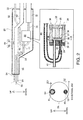
- Fig. 2 shows the internal structure of the hand piece 20.
- the hand piece 20 incorporates a pulsation generating unit 30, an inlet channel 40, an outlet channel 41, and a connection tube 54 and includes a suction force adjusting mechanism 65.
- the pulsation generating unit 30 includes, as shown in the lower part of Fig. 2 , a first case 31, a second case 32, a third case 33, bolts 34, a piezoelectric element 35, a reinforcing plate 36, a diaphragm 37, a gasket 38, the inlet channel 40, and the outlet channel 41.
- the first case 31 and the second case 32 are opposed and joined to each other.
- the first case 31 is a cylindrical member. One end portion of the first case 31 is closed by fixing the third case 33 with the bolts 34.
- the piezoelectric element 35 is arranged in a space formed on the inside of the first case 31.
- the piezoelectric element 35 is a laminated piezoelectric element. One end of the piezoelectric element 35 is fixedly attached to the diaphragm 37 via the reinforcing plate 36. The other end of the piezoelectric element 35 is fixedly attached to the third case 33.
- the diaphragm 37 is made of a metal thin film. The peripheral edge portion of the diaphragm 37 is fixedly attached to the first case 31.
- a fluid chamber 39 is formed between the diaphragm 37 and the second case 32. The volume of the fluid chamber 39 is varied by the driving of the piezoelectric element 35.
- the signal cable 72 is inserted from a rear end portion 22 of the hand piece 20.
- Two electrode lines 74 are housed in the signal cable 72 and connected to the piezoelectric element 35 in the pulsation generating unit 30.
- the drive signal transmitted from the control unit 70 is transmitted to the piezoelectric element 35 via the electrode lines 74 in the signal cable 72.
- the piezoelectric element 35 expands and contracts on the basis of the drive signal.
- the inlet channel 40 into which the fluid flows, is connected to the second case 32.
- the inlet channel 40 is bent in a U shape and extends toward the rear end portion 22 of the hand piece 20.
- the fluid supplying channel 52 is connected to the inlet channel 40.
- the fluid supplied from the fluid supplying mechanism 50 is supplied to the fluid chamber 39 via the fluid supplying channel 52.
- the piezoelectric element 35 expands and contracts at a predetermined frequency (e.g., 10 to 1000 Hz), the diaphragm 37 vibrates.
- a predetermined frequency e.g. 10 to 1000 Hz
- the diaphragm 37 vibrates, the volume of the fluid chamber 39 varies and the pressure of the fluid in the fluid chamber 39 pulsates.
- the fluid passed through the fluid chamber 39 flows out from the outlet channel 41.
- the outlet channel 41 is connected to the second case 32.
- the ejection pipe 55 is connected to the outlet channel 41 via the connection tube 54.
- the fluid flowed out to the outlet channel 41 is ejected from the ejection port 58 through the connection tube 54 and the ejection pipe 55.
- the suction force adjusting mechanism 65 is a mechanism for adjusting a force of the suction channel 62 for sucking the fluid or the like from the suction port 64.
- the suction force adjusting mechanism 65 includes an operation unit 66 and a hole 67.
- the hole 67 is a through-hole that connects the suction channel 62 and the operation unit 66.
- the hole 67 is preferably faced upward in the vertical direction because a sucked object is discharged to the outside from the hole 67 by gravity. This phenomenon guides the user to grip the hand piece 20 in a posture in which the hole 67 is faced upward in the vertical direction.
- the axial direction of the hole 67 is defined as "up down direction”.
- a direction from a connecting place of the hole 67 and the suction channel 62 to an opening section of the hole 67 is defined as "upward in the up down direction”. In the following explanation, when "upward” is simply referred to, this indicates upward in the up down direction.
- the suction force adjusting mechanism 65 does not force the user to adopt a certain method of use of the hand piece 20.
- a connecting part of the fluid chamber 39 and the outlet channel 41 (hereinafter referred to as "outlet part") and a connecting part of the fluid chamber 39 and the inlet channel 40 (hereinafter referred to as “inlet part”) are arranged to be opposed to each other via the vicinity of the center of the fluid chamber 39.
- the outlet part is arranged above the inlet part. Therefore, air bubbles easily move to the vicinity of the outlet part with buoyancy according to the influence of the gravity. Discharge of the air bubbles is facilitated.
- a relation of upper and lower is not limited to a positional relation of right above and right under and also include a relation of high and low.
- a channel area S1 of the outlet part is larger than a channel area S2 of the inlet part and is, for example, five times as large as the channel area S2.
- the pressure of the fluid in the fluid chamber 39 properly pulsates.
- the vicinity of the center of the fluid chamber 39 is the center of the side surface of the fluid chamber 39 to which the inlet part and the outlet part are connected. When the distance from the center to the side surface is represented as t, the vicinity of the center of the fluid chamber 39 is within a range of 0.25t.
- a distance G1 from the inner wall of the outlet part to the edge of the fluid chamber 39 is shorter than a distance G2 from the inner wall of the inlet part to the edge of the fluid chamber 39. Consequently, the air bubbles less easily accumulate between the inner wall of the outlet channel 41 and the edge of the fluid chamber 39.
- the hand piece 20 corresponds to a container
- the piezoelectric element 35 and the diaphragm 37 correspond to a volume varying unit
- the inlet channel 40 corresponds to a first channel
- the outlet channel 41 corresponds to a second channel
- the fluid supplying mechanism 50 corresponds to a fluid supplying unit
- the suction force adjusting mechanism 65 corresponds to a guiding section and an up down direction defining unit.
- Fig. 3 shows the configuration of a fluid ejection device 10a in a second embodiment.
- the fluid ejection device 10a is different from the fluid ejection device 10 in the first embodiment in that the fluid ejection device 10a includes a hand piece 20a instead of the hand piece 20.
- the hand piece 20a includes a grip 68 including concave and convex shapes on the outer side as shown in Fig. 3 .
- the grip 68 makes it easy to grip the hand piece 20a and guides a user to grip the hand piece 20a in a posture in which the outlet channel 41 is located above the inlet channel 40. That is, the grip 68 corresponds to the guiding section in the appended claims.
- Fig. 4 shows the configuration of a fluid ejection device 10b in a third embodiment.
- the fluid ejection device 10b is different from the fluid ejection device 10 in the first embodiment in that the fluid ejection device 10b includes a hand piece 20b instead of the hand piece 20.
- the hand piece 20b includes a curved section 69 as shown in Fig. 4 .
- the curved section 69 is a part of the ejection pipe 55 and is a part curved in a part exposed from the hand piece 20b.
- the curved section 69 bends in a direction parallel to a specific plane and does not bend in a direction orthogonal to the specific plane.
- the specific plane is a plane including the up down direction and the axis of the ejection pipe 55 in a straight part.
- the curved section 69 makes it easy to eject the fluid to a target position and guides a user to grip the hand piece 20b in a posture in which the outlet channel 41 is located above the inlet channel 40. That is, the curved section 69 corresponds to the guiding section in the appended claims.
- a method of realizing the guiding section may be a combination of a plurality of methods. For example, two or three among the suction force adjusting mechanism, the grip, and the curved section may be combined or other methods may be further combined.
- the area of the outlet channel may be smaller or larger than five times with respect to the area of the inlet channel.
- the up down direction may be defined by drawing, on the hand piece, a line work such as an arrow or a character indicating the up down direction.
- the up down direction of the hand piece may be defined by forming the sectional shape of the hand piece as an ellipse and drawing out the ejection pipe from above the center of the ellipse at the distal end portion of the hand piece.
- An inclination sensor and a level may be mounted on the hand piece to inform the user of the up down direction using results of measurement by the inclination sensor and the level.
- a posture of the hand piece may be read using a sensor provided on the outside of the hand piece to inform the user of the up down direction.
- the up down direction defining unit may be realized by a function exerted by the hand piece alone.
- the up down direction defining unit may be realized by a function exerted by a device other than the hand piece and included in the fluid ejection device.
- the up down direction defining unit may be realized by a function exerted by the fluid ejection device and another device in cooperation with each other.
- the up down direction defining unit may define the up down direction as a direction of use of the container when the user uses the fluid ejection device.
- the up down direction defining unit may define the up down direction of the container on the basis of a direction of the container in which the function and the characteristics are suitably exerted.
- the up down direction defining unit may provide the user of the fluid ejection device with information for defining the up down direction of the container with respect to at least any one of the visual sense, the tactile sense, the auditory sense, and the like of the user.
- the up down direction defining unit may guide the user to use the container in a predetermined posture using various elements included in the fluid ejection device.
- the various elements are a shape, a pattern, a color, a line work, a character, a mark, sound, light, operability, design, and the like.
- the up down direction defining unit may suppress, with the various elements included in the fluid ejection device, the user from using the fluid ejection device in a direction other than the up down direction defined in advance.
- the fluid ejection device may be used in apparatuses other than the medical apparatus.
- the fluid ejection device may be used in a cleaning apparatus that removes stains using ejected fluid.
- the fluid ejection device may be used in a rendering apparatus that draws a line or the like using ejected fluid.
Landscapes
- Health & Medical Sciences (AREA)
- Life Sciences & Earth Sciences (AREA)
- Surgery (AREA)
- Molecular Biology (AREA)
- General Health & Medical Sciences (AREA)
- Biomedical Technology (AREA)
- Heart & Thoracic Surgery (AREA)
- Medical Informatics (AREA)
- Nuclear Medicine, Radiotherapy & Molecular Imaging (AREA)
- Animal Behavior & Ethology (AREA)
- Engineering & Computer Science (AREA)
- Public Health (AREA)
- Veterinary Medicine (AREA)
- Surgical Instruments (AREA)
- Ink Jet (AREA)
- Particle Formation And Scattering Control In Inkjet Printers (AREA)
- Containers And Packaging Bodies Having A Special Means To Remove Contents (AREA)
Abstract
Description
- The present invention relates to ejection of fluid.
- There is known a fluid ejection device that varies the volume of a fluid chamber using an actuator including a piezoelectric element and generates pulsation in the pressure of the fluid in the fluid chamber to thereby intermittently eject the fluid (e.g.,
JP-A-2008-82202 - A problem of the related art is that air bubbles tend to accumulate in the fluid chamber. The air bubbles in the fluid chamber are generated from the fluid in the fluid chamber by the volume variation of the fluid chamber. When the air bubbles accumulate in the fluid chamber, the volume variation of the fluid chamber is absorbed by volume variation of the air bubbles. Therefore, appropriate pulsation sometimes cannot be generated.
- An advantage of some aspects of the invention is to solve at least a part of the problems described above, and the invention can be implemented as the following aspects.
- (1) An aspect of the invention provides a fluid ejection device. The fluid ejection device includes: a pulsation giving unit for ejecting fluid in a fluid chamber; a fluid supplying unit configured to supply the fluid to the fluid chamber through a first channel; and an ejection pipe configured to communicate with a second channel, which communicates with the pulsation giving unit, and eject the fluid from an ejection port. The cross-sectional area of the second channel is five times or more as large as the cross-sectional area of the first channel. A connecting part of the first channel and the fluid chamber and a connecting part of the second channel and the fluid chamber are arranged in positions opposed to each other via the vicinity of the center of the fluid chamber. According to this aspect of the invention, air bubbles in the fluid chamber are easily discharged through the ejection pipe. This is because, since the connecting part of the first channel and the fluid chamber and the connecting part of the second channel and the fluid chamber are arranged in the positions opposed to each other via the vicinity of the center of the fluid chamber, a flow in the fluid chamber less easily stagnate and, in addition, since the cross-sectional area of the second channel is five times or more as large as the cross-sectional area of the first channel, the air bubbles easily flows into the ejection pipe.
- (2) Another aspect of the invention provides the fluid ejection device according to the aspect described above, wherein the connecting part of the second channel and the fluid chamber is arranged in a position closer to an edge of the fluid chamber than the connecting part of the first channel and the fluid chamber. According to this aspect of the invention, the air bubbles in the fluid chamber are more easily discharged. This is because, since the connecting part of the second channel and the fluid chamber is arranged in the position closer to the edge of the fluid chamber than the connecting part of the first channel and the fluid chamber, the air bubbles are suppressed from accumulating between the second channel and the edge of the fluid chamber.
- (3) Still another aspect of the invention provides the fluid ejection device according to the aspect described above, wherein the fluid ejection device further includes a guiding section configured to guide a user to use the fluid ejection device in a state in which the connecting part of the second channel and the fluid chamber is located above the connecting part of the first channel and the fluid chamber in the vertical direction. According to this aspect of the invention, the air bubbles in the fluid chamber are more easily discharged. Since the guiding section guide the user to use the fluid ejection device in the state in which the connecting part of the second channel and the fluid chamber is located above the connecting part of the first channel and the fluid chamber in the vertical direction, it is more likely that the fluid ejection device is used in the state in which the connecting part of the second channel and the fluid chamber is located above the connecting part of the first channel and the fluid chamber. If the fluid ejection device is used in the state in which the connecting part of the second channel and the fluid chamber is located above the connecting part of the first channel and the fluid chamber, the air bubbles easily move to the vicinity of the connecting part of the second channel and the fluid chamber with buoyancy according to the influence of the gravity. As a result, it is possible to obtain the effect explained above.
- (4) This aspect of the invention provides the fluid ejection device according to the aspect described above, wherein the fluid ejection device further includes: a suction channel for sucking the fluid present around the ejection port; a container configured to house at least a part of the ejection pipe, at least a part of fluid supplying channel connecting the fluid supplying unit and the first channel, the pulsation giving unit, and at least a part of the suction channel; and a suction adjusting mechanism for adjusting a degree of suction by the suction channel, the suction adjusting mechanism includes an operation unit provided in the container, and the guiding section is the operation unit. According to this aspect of the invention, it is possible to realize the guide using the operation unit.
- (5) Yet another aspect of the invention provides the fluid ejection device according to the aspect described above, wherein the fluid ejection device further includes a container configured to house at least a part of the ejection pipe, at least a part of fluid supplying channel connecting the fluid supplying unit and the first channel, and the pulsation giving unit, and the guiding section is a grip provided in the container. According to this aspect of the invention, it is possible to realize the guide using the grip.
- (6) Still yet another aspect of the invention provides the fluid ejection device according to the aspect described above, wherein the fluid ejection device further includes a container configured to house a part of the ejection pipe, at least a part of fluid supplying channel connecting the fluid supplying unit and the first channel , and the pulsation giving unit, and the guiding section is a curved section located on the outside of the container as a part of the ejection pipe. According to this aspect of the invention, it is possible to realize the guide using the curved section.
- (7) Further another aspect of the invention provides a fluid ejection device including: a volume varying unit configured to generate pulsation in fluid in a fluid chamber; a fluid supplying unit configured to supply the fluid to the fluid chamber through a first channel; an ejection pipe configured to receive the supply of the fluid, in which the pulsation is generated, from the volume varying unit through a second channel and eject the supplied fluid from an ejection port; and an up down direction defining unit configured to define an up down direction of the volume varying unit. The cross-sectional area of the second channel is larger than the cross-sectional area of the first channel. The second channel is arranged above the first channel on the basis of the definition by the up down direction defining unit. According to this aspect of the invention, air bubbles in the fluid chamber are easily discharged through the ejection pipe. This is because the second channel is arranged above the first channel and, in addition, the cross-sectional area of the second channel is larger than the cross sectional area of the first channel.
- (8) Still further another aspect of the invention provides a medical apparatus including the fluid ejection device according to the aspect of the invention described above. According to this aspect of the invention, it is possible to provide a medical apparatus including the fluid ejection device in which air bubbles less easily accumulate in the fluid chamber.
- Not all of the plurality of components of the aspects of the invention explained above are essential. In order to solve a part or all of the problems explained above or in order to attain a part or all of the effects described in this specification, a part of the plurality of components can be changed, deleted, and replaced with other new components as appropriate and delete a part of limitations of the components. In order to solve a part or all of the problems explained above or in order to attain a part or all of the effects described in this specification, a part or all of the technical features included in one of the aspects of the invention explained above can be combined with a part or all of the technical features included in the other aspects of the invention as an independent form of the invention.
- For example, one of the aspects of the invention can be implemented as a device including a part or all of the volume varying unit, the fluid supplying unit, and the ejection pipe. The device may include or may not include the volume varying unit. The device may or may not include the fluid supplying unit. The device may or may not include the ejection pipe. For example, the volume varying unit may vary the volume in the fluid chamber. For example, the fluid supplying unit may supply the fluid to the fluid chamber through the first channel. For example, the ejection pipe may communicate with the second channel, which communicates with the volume varying unit, and eject the fluid from the ejection port. The cross-sectional area of the second channel may be five times or more as large as the cross-sectional area of the first channel. The first channel and the second channel may be arranged to be opposed to each other via the vicinity of the center of the volume varying unit. Such a device can be implemented as, for example, a fluid ejection device and can be implemented as devices other than the fluid ejection device. According to such a form, it is possible to solve at least one of the various objects such as a reduction in the size of the device, a reduction in costs, resource saving, simplification of manufacturing, and improvement of convenience of use. A part or all of the technical features of the aspects of the fluid ejection device explained above can be applied to this device.
- The invention can also be implemented in various forms other than the forms explained above. For example, the invention can be implemented in forms such as a fluid ejection method, a surgical operation method, computer programs for implementing these methods, and storage media having these computer programs stored therein.
- The invention will be described with reference to the accompanying drawings, wherein like numbers reference like elements.
-
Fig. 1 is a configuration diagram of a fluid ejection device in a first embodiment. -
Fig. 2 is an internal structure diagram of a hand piece. -
Fig. 3 is a configuration diagram of a fluid ejection device in a second embodiment. -
Fig. 4 is a configuration diagram of a fluid ejection device in a third embodiment. -
Fig. 1 shows the configuration of afluid ejection device 10. Thefluid ejection device 10 is a medical device used in a medical institution. Thefluid ejection device 10 has a function of incising or excising an affected part by ejecting fluid to the affected part. - The
fluid ejection device 10 includes ahand piece 20, afluid supplying mechanism 50, asuction device 60, acontrol unit 70, and afluid container 80. Thefluid supplying mechanism 50 and thefluid container 80 are connected to each other by aconnection tube 51. Thefluid supplying mechanism 50 and thehand piece 20 are connected to each other by afluid supplying channel 52. At least a part of theconnection tube 51 and thefluid supplying channel 52 are formed of resin. At least a part of theconnection tube 51 and thefluid supplying channel 52 may be formed of a material (e.g., rubber or metal) other than the resin. - The
fluid container 80 stores saline. Thefluid supplying mechanism 50 supplies fluid sucked from thefluid container 80 via theconnection tube 51 to thehand piece 20 via thefluid supplying channel 52. - The
hand piece 20 is an instrument held and operated by a user of thefluid ejection device 10. Apulsation generating unit 30 incorporated in thehand piece 20 generates pulsation of the pressure of the fluid supplied to thehand piece 20 from thefluid supplying mechanism 50 via thefluid supplying channel 52. The fluid, in which the pulsation of the pressure is generated, is supplied to anejection pipe 55. The fluid supplied to theejection pipe 55 is intermittently ejected from anejection port 58. The user hits the fluid ejected from theejection port 58 on an affected part to thereby incise or excise the affected part. Theejection pipe 55 is formed of stainless steel. At least a part of theejection pipe 55 may be formed of other materials having predetermined or higher rigidity such as other kinds of metal such as brass and reinforced plastics. - The
control unit 70 transmits a drive signal to thepulsation generating unit 30 via asignal cable 72. Thecontrol unit 70 controls thefluid supplying mechanism 50 via acontrol cable 71 to thereby control a flow rate of the fluid supplied to thepulsation generating unit 30. Afoot switch 75 is connected to thecontrol unit 70. When the user turns on thefoot switch 75, thecontrol unit 70 controls thefluid supplying mechanism 50 to execute the supply of the fluid to thepulsation generating unit 30. Thecontrol unit 70 transmits the drive signal to thepulsation generating unit 30 and causes thepulsation generating unit 30 to generate pulsation in the pressure of the fluid supplied to thepulsation generating unit 30. - The
suction device 60 is a device for sucking the fluid and an excised object around theejection port 58. Thesuction device 60 and thehand piece 20 are connected to each other by asuction channel 62. Thesuction channel 62 pierces through thehand piece 20 and opens near the distal end of theejection pipe 55. Thesuction channel 62 covers theejection pipe 55 in thehand piece 20 to thereby form a cylinder in which the wall of theejection pipe 55 and the wall of thesuction channel 62 are substantially concentric as shown in an A arrow view ofFig. 1 . A channel through which a sucked object sucked from asuction port 64, which is the distal end of thesuction channel 62, flows is formed between the outer wall of theejection pipe 55 and the inner wall of thesuction channel 62. The sucked object is sucked by thesuction device 60 via thesuction channel 62. -
Fig. 2 shows the internal structure of thehand piece 20. Thehand piece 20 incorporates apulsation generating unit 30, aninlet channel 40, anoutlet channel 41, and aconnection tube 54 and includes a suctionforce adjusting mechanism 65. - The
pulsation generating unit 30 includes, as shown in the lower part ofFig. 2 , afirst case 31, asecond case 32, athird case 33,bolts 34, apiezoelectric element 35, a reinforcingplate 36, adiaphragm 37, agasket 38, theinlet channel 40, and theoutlet channel 41. Thefirst case 31 and thesecond case 32 are opposed and joined to each other. Thefirst case 31 is a cylindrical member. One end portion of thefirst case 31 is closed by fixing thethird case 33 with thebolts 34. Thepiezoelectric element 35 is arranged in a space formed on the inside of thefirst case 31. - The
piezoelectric element 35 is a laminated piezoelectric element. One end of thepiezoelectric element 35 is fixedly attached to thediaphragm 37 via the reinforcingplate 36. The other end of thepiezoelectric element 35 is fixedly attached to thethird case 33. Thediaphragm 37 is made of a metal thin film. The peripheral edge portion of thediaphragm 37 is fixedly attached to thefirst case 31. Afluid chamber 39 is formed between thediaphragm 37 and thesecond case 32. The volume of thefluid chamber 39 is varied by the driving of thepiezoelectric element 35. - The
signal cable 72 is inserted from arear end portion 22 of thehand piece 20. Twoelectrode lines 74 are housed in thesignal cable 72 and connected to thepiezoelectric element 35 in thepulsation generating unit 30. The drive signal transmitted from thecontrol unit 70 is transmitted to thepiezoelectric element 35 via theelectrode lines 74 in thesignal cable 72. Thepiezoelectric element 35 expands and contracts on the basis of the drive signal. - The
inlet channel 40, into which the fluid flows, is connected to thesecond case 32. Theinlet channel 40 is bent in a U shape and extends toward therear end portion 22 of thehand piece 20. Thefluid supplying channel 52 is connected to theinlet channel 40. The fluid supplied from thefluid supplying mechanism 50 is supplied to thefluid chamber 39 via thefluid supplying channel 52. - The
piezoelectric element 35 expands and contracts at a predetermined frequency (e.g., 10 to 1000 Hz), thediaphragm 37 vibrates. When thediaphragm 37 vibrates, the volume of thefluid chamber 39 varies and the pressure of the fluid in thefluid chamber 39 pulsates. The fluid passed through thefluid chamber 39 flows out from theoutlet channel 41. - The
outlet channel 41 is connected to thesecond case 32. Theejection pipe 55 is connected to theoutlet channel 41 via theconnection tube 54. The fluid flowed out to theoutlet channel 41 is ejected from theejection port 58 through theconnection tube 54 and theejection pipe 55. - On the other hand, the suction
force adjusting mechanism 65 is a mechanism for adjusting a force of thesuction channel 62 for sucking the fluid or the like from thesuction port 64. The suctionforce adjusting mechanism 65 includes anoperation unit 66 and ahole 67. Thehole 67 is a through-hole that connects thesuction channel 62 and theoperation unit 66. When the user opens and closes thehole 67 with a finger of the hand that grips thehand piece 20, an amount of the air flowing into thesuction channel 62 via thehole 67 is adjusted according to a degree of the opening and closing. Consequently, a suction force of thesuction port 64 is adjusted. The adjustment of the suction force can also be realized by control by thesuction device 60. - The
hole 67 is preferably faced upward in the vertical direction because a sucked object is discharged to the outside from thehole 67 by gravity. This phenomenon guides the user to grip thehand piece 20 in a posture in which thehole 67 is faced upward in the vertical direction. In the following explanation, the axial direction of thehole 67 is defined as "up down direction". A direction from a connecting place of thehole 67 and thesuction channel 62 to an opening section of thehole 67 is defined as "upward in the up down direction". In the following explanation, when "upward" is simply referred to, this indicates upward in the up down direction. - In the
fluid ejection device 10, when thehole 67 is faced upward, the positions of the components are determined to make the function and operability of the suctionforce adjusting mechanism 65 preferable. However, the suctionforce adjusting mechanism 65 does not force the user to adopt a certain method of use of thehand piece 20. - As shown in the B-B sectional view of
Fig. 2 , a connecting part of thefluid chamber 39 and the outlet channel 41 (hereinafter referred to as "outlet part") and a connecting part of thefluid chamber 39 and the inlet channel 40 (hereinafter referred to as "inlet part") are arranged to be opposed to each other via the vicinity of the center of thefluid chamber 39. The outlet part is arranged above the inlet part. Therefore, air bubbles easily move to the vicinity of the outlet part with buoyancy according to the influence of the gravity. Discharge of the air bubbles is facilitated. A relation of upper and lower is not limited to a positional relation of right above and right under and also include a relation of high and low. A channel area S1 of the outlet part is larger than a channel area S2 of the inlet part and is, for example, five times as large as the channel area S2. According to the arrangement and the difference of the channel areas, when the volume of thefluid chamber 39 varies, a backf low of the fluid to theinlet channel 40 is suppressed and the discharge of the air bubbles from thefluid chamber 39 to theinlet channel 40 is facilitated. Consequently, the discharge of the remaining air bubbles discharged during filling of the fluid and mixed air bubbles during use is facilitated. The pressure of the fluid in thefluid chamber 39 properly pulsates. The vicinity of the center of thefluid chamber 39 is the center of the side surface of thefluid chamber 39 to which the inlet part and the outlet part are connected. When the distance from the center to the side surface is represented as t, the vicinity of the center of thefluid chamber 39 is within a range of 0.25t. - As shown in the B-B sectional view of
Fig. 2 , a distance G1 from the inner wall of the outlet part to the edge of thefluid chamber 39 is shorter than a distance G2 from the inner wall of the inlet part to the edge of thefluid chamber 39. Consequently, the air bubbles less easily accumulate between the inner wall of theoutlet channel 41 and the edge of thefluid chamber 39. - A correspondence relation between the first embodiment and the appended claims is explained. The
hand piece 20 corresponds to a container, thepiezoelectric element 35 and thediaphragm 37 correspond to a volume varying unit, theinlet channel 40 corresponds to a first channel, theoutlet channel 41 corresponds to a second channel, thefluid supplying mechanism 50 corresponds to a fluid supplying unit, and the suctionforce adjusting mechanism 65 corresponds to a guiding section and an up down direction defining unit. -
Fig. 3 shows the configuration of afluid ejection device 10a in a second embodiment. Thefluid ejection device 10a is different from thefluid ejection device 10 in the first embodiment in that thefluid ejection device 10a includes ahand piece 20a instead of thehand piece 20. - The
hand piece 20a includes agrip 68 including concave and convex shapes on the outer side as shown inFig. 3 . Thegrip 68 makes it easy to grip thehand piece 20a and guides a user to grip thehand piece 20a in a posture in which theoutlet channel 41 is located above theinlet channel 40. That is, thegrip 68 corresponds to the guiding section in the appended claims. -
Fig. 4 shows the configuration of afluid ejection device 10b in a third embodiment. Thefluid ejection device 10b is different from thefluid ejection device 10 in the first embodiment in that thefluid ejection device 10b includes ahand piece 20b instead of thehand piece 20. - The
hand piece 20b includes acurved section 69 as shown inFig. 4 . Thecurved section 69 is a part of theejection pipe 55 and is a part curved in a part exposed from thehand piece 20b. Thecurved section 69 bends in a direction parallel to a specific plane and does not bend in a direction orthogonal to the specific plane. The specific plane is a plane including the up down direction and the axis of theejection pipe 55 in a straight part. - The
curved section 69 makes it easy to eject the fluid to a target position and guides a user to grip thehand piece 20b in a posture in which theoutlet channel 41 is located above theinlet channel 40. That is, thecurved section 69 corresponds to the guiding section in the appended claims. - The invention is not limited to the embodiments, examples, and modifications described in this specification and can be realized in various configurations without departing from the spirit of the invention. For example, technical features of the embodiments, the examples, and the modifications corresponding to technical features in the forms described in the summary of the invention can be replaced or combined as appropriate in order to solve a part or all of the problems explained above or attain a part or all of the effects explained above. Unless the technical features are not explained in this specification as essential technical features, the technical features can be deleted as appropriate. Technical features explained below are examples of such technical features.
- A method of realizing the guiding section may be a combination of a plurality of methods. For example, two or three among the suction force adjusting mechanism, the grip, and the curved section may be combined or other methods may be further combined. The area of the outlet channel may be smaller or larger than five times with respect to the area of the inlet channel.
- The up down direction may be defined by drawing, on the hand piece, a line work such as an arrow or a character indicating the up down direction. The up down direction of the hand piece may be defined by forming the sectional shape of the hand piece as an ellipse and drawing out the ejection pipe from above the center of the ellipse at the distal end portion of the hand piece. An inclination sensor and a level may be mounted on the hand piece to inform the user of the up down direction using results of measurement by the inclination sensor and the level. A posture of the hand piece may be read using a sensor provided on the outside of the hand piece to inform the user of the up down direction.
- The up down direction defining unit may be realized by a function exerted by the hand piece alone. The up down direction defining unit may be realized by a function exerted by a device other than the hand piece and included in the fluid ejection device. The up down direction defining unit may be realized by a function exerted by the fluid ejection device and another device in cooperation with each other.
- The up down direction defining unit may define the up down direction as a direction of use of the container when the user uses the fluid ejection device. When the function and the characteristic of the fluid ejection device change according to the direction of the container, the up down direction defining unit may define the up down direction of the container on the basis of a direction of the container in which the function and the characteristics are suitably exerted. The up down direction defining unit may provide the user of the fluid ejection device with information for defining the up down direction of the container with respect to at least any one of the visual sense, the tactile sense, the auditory sense, and the like of the user. The up down direction defining unit may guide the user to use the container in a predetermined posture using various elements included in the fluid ejection device. The various elements are a shape, a pattern, a color, a line work, a character, a mark, sound, light, operability, design, and the like. The up down direction defining unit may suppress, with the various elements included in the fluid ejection device, the user from using the fluid ejection device in a direction other than the up down direction defined in advance.
- The fluid ejection device may be used in apparatuses other than the medical apparatus. For example, the fluid ejection device may be used in a cleaning apparatus that removes stains using ejected fluid. The fluid ejection device may be used in a rendering apparatus that draws a line or the like using ejected fluid.
Claims (14)
the guiding section is a grip provided in the container.
the guiding section is a curved section located on an outside of the container as a part of the ejection pipe.
Applications Claiming Priority (1)
| Application Number | Priority Date | Filing Date | Title |
|---|---|---|---|
| JP2013071219A JP6229286B2 (en) | 2013-03-29 | 2013-03-29 | Liquid ejector, medical equipment |
Publications (2)
| Publication Number | Publication Date |
|---|---|
| EP2783646A1 true EP2783646A1 (en) | 2014-10-01 |
| EP2783646B1 EP2783646B1 (en) | 2016-09-28 |
Family
ID=50382336
Family Applications (1)
| Application Number | Title | Priority Date | Filing Date |
|---|---|---|---|
| EP14161975.9A Not-in-force EP2783646B1 (en) | 2013-03-29 | 2014-03-27 | Fluid ejection device and medical apparatus |
Country Status (4)
| Country | Link |
|---|---|
| US (1) | US9662135B2 (en) |
| EP (1) | EP2783646B1 (en) |
| JP (1) | JP6229286B2 (en) |
| CN (1) | CN104068917A (en) |
Families Citing this family (7)
| Publication number | Priority date | Publication date | Assignee | Title |
|---|---|---|---|---|
| JP2014206088A (en) * | 2013-04-12 | 2014-10-30 | セイコーエプソン株式会社 | Liquid injection device and medical equipment |
| JP2015198862A (en) * | 2014-04-10 | 2015-11-12 | セイコーエプソン株式会社 | Fluid ejection device |
| JP2015198865A (en) * | 2014-04-10 | 2015-11-12 | セイコーエプソン株式会社 | Fluid injection device |
| JP2015198864A (en) * | 2014-04-10 | 2015-11-12 | セイコーエプソン株式会社 | Fluid injection device |
| WO2018071691A1 (en) * | 2016-10-12 | 2018-04-19 | Boston Scientific Scimed, Inc. | Thrombectomy catheter |
| JP7272161B2 (en) * | 2019-07-31 | 2023-05-12 | セイコーエプソン株式会社 | liquid injector |
| JP7443845B2 (en) * | 2020-03-16 | 2024-03-06 | セイコーエプソン株式会社 | liquid injection device |
Citations (6)
| Publication number | Priority date | Publication date | Assignee | Title |
|---|---|---|---|---|
| JP2008082202A (en) | 2006-09-26 | 2008-04-10 | Seiko Epson Corp | Fluid ejection device |
| US20090043480A1 (en) * | 2007-08-10 | 2009-02-12 | Seiko Epson Corporation | Fluid injection device |
| US20090270799A1 (en) * | 2008-04-24 | 2009-10-29 | Seiko Epson Corporation | Fluid injection device |
| US20100069937A1 (en) * | 2008-09-16 | 2010-03-18 | Seiko Epson Corporation | Fluid jet device, drive device of fluid jet device, surgical instrument, and method of driving fluid jet device |
| US20110208224A1 (en) * | 2010-02-22 | 2011-08-25 | Seiko Epson Corporation | Liquid injection device |
| US20120181352A1 (en) * | 2011-01-18 | 2012-07-19 | Seiko Epson Corporation | Liquid ejecting apparatus |
Family Cites Families (15)
| Publication number | Priority date | Publication date | Assignee | Title |
|---|---|---|---|---|
| JPS61279239A (en) | 1985-06-04 | 1986-12-10 | 日本赤外線工業株式会社 | Ultrasonic operation apparatus |
| US5222939A (en) * | 1992-04-09 | 1993-06-29 | Jonathan Tiefenbrun | Instrument and associated method for applying biologically effective composition during surgery |
| US5308673A (en) * | 1992-05-07 | 1994-05-03 | Minnesota Mining And Manufacturing Company | Stitchbonded absorbent articles and method of making same |
| WO1997040750A1 (en) * | 1996-04-25 | 1997-11-06 | Karl Storz Gmbh & Co. | Surgical instrument system |
| DE102004021035B3 (en) * | 2004-04-07 | 2005-11-17 | Erbe Elektromedizin Gmbh | Apparatus for waterjet surgery |
| JP2007151783A (en) * | 2005-12-05 | 2007-06-21 | Kosuke Noda | Spatula with suction function |
| JP5320906B2 (en) | 2008-08-28 | 2013-10-23 | セイコーエプソン株式会社 | Fluid ejection surgical instrument and fluid ejection method |
| JP2010057531A (en) | 2008-09-01 | 2010-03-18 | Seiko Epson Corp | Fluid jetting apparatus, method of controlling the same and surgical apparatus |
| JP2010059792A (en) | 2008-09-01 | 2010-03-18 | Seiko Epson Corp | Fluid injection device, fluid injection unit, control device, method of controlling fluid injection device and operating device |
| JP5277802B2 (en) | 2008-09-05 | 2013-08-28 | セイコーエプソン株式会社 | Fluid ejection device and surgical scalpel |
| JP4752892B2 (en) | 2008-09-30 | 2011-08-17 | セイコーエプソン株式会社 | Fluid ejecting apparatus and surgical instrument |
| JP4778545B2 (en) | 2008-10-20 | 2011-09-21 | セイコーエプソン株式会社 | Fluid ejection device |
| JP5585369B2 (en) * | 2010-10-12 | 2014-09-10 | セイコーエプソン株式会社 | Fluid ejecting apparatus and medical device |
| JP2012145031A (en) | 2011-01-12 | 2012-08-02 | Seiko Epson Corp | Pump, fluid injection apparatus and medical equipment |
| JP5870565B2 (en) * | 2011-09-08 | 2016-03-01 | セイコーエプソン株式会社 | Liquid ejector |
-
2013
- 2013-03-29 JP JP2013071219A patent/JP6229286B2/en not_active Expired - Fee Related
-
2014
- 2014-03-27 EP EP14161975.9A patent/EP2783646B1/en not_active Not-in-force
- 2014-03-27 US US14/227,902 patent/US9662135B2/en not_active Expired - Fee Related
- 2014-03-27 CN CN201410120755.5A patent/CN104068917A/en active Pending
Patent Citations (6)
| Publication number | Priority date | Publication date | Assignee | Title |
|---|---|---|---|---|
| JP2008082202A (en) | 2006-09-26 | 2008-04-10 | Seiko Epson Corp | Fluid ejection device |
| US20090043480A1 (en) * | 2007-08-10 | 2009-02-12 | Seiko Epson Corporation | Fluid injection device |
| US20090270799A1 (en) * | 2008-04-24 | 2009-10-29 | Seiko Epson Corporation | Fluid injection device |
| US20100069937A1 (en) * | 2008-09-16 | 2010-03-18 | Seiko Epson Corporation | Fluid jet device, drive device of fluid jet device, surgical instrument, and method of driving fluid jet device |
| US20110208224A1 (en) * | 2010-02-22 | 2011-08-25 | Seiko Epson Corporation | Liquid injection device |
| US20120181352A1 (en) * | 2011-01-18 | 2012-07-19 | Seiko Epson Corporation | Liquid ejecting apparatus |
Also Published As
| Publication number | Publication date |
|---|---|
| JP6229286B2 (en) | 2017-11-15 |
| JP2014193578A (en) | 2014-10-09 |
| CN104068917A (en) | 2014-10-01 |
| EP2783646B1 (en) | 2016-09-28 |
| US9662135B2 (en) | 2017-05-30 |
| US20140296896A1 (en) | 2014-10-02 |
Similar Documents
| Publication | Publication Date | Title |
|---|---|---|
| US9662135B2 (en) | Fluid ejection device and medical apparatus | |
| JP6127642B2 (en) | Liquid ejecting apparatus and medical device | |
| US9433434B2 (en) | Fluid ejection device and medical instrument | |
| US20170014149A1 (en) | Liquid Ejection Device and Surgical Apparatus | |
| EP2848218A1 (en) | Liquid ejecting apparatus and medical device | |
| CN104417057A (en) | Liquid ejecting apparatus, liquid ejecting method, and medical instrument | |
| US9610090B2 (en) | Liquid injection device and medical device | |
| US20140316452A1 (en) | Liquid ejection device and medical apparatus | |
| US20140309674A1 (en) | Liquid ejection device and medical apparatus | |
| US20140296893A1 (en) | Liquid ejection device and medical apparatus | |
| JP5879904B2 (en) | Channel pipe and fluid ejection device | |
| JP2016214341A (en) | Support, operation unit, and liquid ejection device | |
| JP2009045166A (en) | Fluid ejection device | |
| CN104414710A (en) | Liquid ejection device and medical apparatus | |
| US20150073453A1 (en) | Medical device | |
| US20140296891A1 (en) | Fluid ejection device and medical apparatus | |
| JP6089868B2 (en) | Liquid ejecting apparatus and medical device | |
| US20160303855A1 (en) | Operation section and liquid ejection device | |
| JP6149456B2 (en) | Liquid ejecting apparatus and medical device | |
| CN104414706A (en) | Medical instrument storage apparatus | |
| JP2016067593A (en) | Operation unit and liquid ejection device |
Legal Events
| Date | Code | Title | Description |
|---|---|---|---|
| 17P | Request for examination filed |
Effective date: 20140327 |
|
| AK | Designated contracting states |
Kind code of ref document: A1 Designated state(s): AL AT BE BG CH CY CZ DE DK EE ES FI FR GB GR HR HU IE IS IT LI LT LU LV MC MK MT NL NO PL PT RO RS SE SI SK SM TR |
|
| AX | Request for extension of the european patent |
Extension state: BA ME |
|
| PUAI | Public reference made under article 153(3) epc to a published international application that has entered the european phase |
Free format text: ORIGINAL CODE: 0009012 |
|
| R17P | Request for examination filed (corrected) |
Effective date: 20150305 |
|
| RBV | Designated contracting states (corrected) |
Designated state(s): AL AT BE BG CH CY CZ DE DK EE ES FI FR GB GR HR HU IE IS IT LI LT LU LV MC MK MT NL NO PL PT RO RS SE SI SK SM TR |
|
| 17Q | First examination report despatched |
Effective date: 20150415 |
|
| GRAP | Despatch of communication of intention to grant a patent |
Free format text: ORIGINAL CODE: EPIDOSNIGR1 |
|
| INTG | Intention to grant announced |
Effective date: 20160404 |
|
| RAP1 | Party data changed (applicant data changed or rights of an application transferred) |
Owner name: SEIKO EPSON CORPORATION |
|
| GRAS | Grant fee paid |
Free format text: ORIGINAL CODE: EPIDOSNIGR3 |
|
| GRAA | (expected) grant |
Free format text: ORIGINAL CODE: 0009210 |
|
| RAP1 | Party data changed (applicant data changed or rights of an application transferred) |
Owner name: SEIKO EPSON CORPORATION |
|
| AK | Designated contracting states |
Kind code of ref document: B1 Designated state(s): AL AT BE BG CH CY CZ DE DK EE ES FI FR GB GR HR HU IE IS IT LI LT LU LV MC MK MT NL NO PL PT RO RS SE SI SK SM TR |
|
| REG | Reference to a national code |
Ref country code: GB Ref legal event code: FG4D |
|
| REG | Reference to a national code |
Ref country code: CH Ref legal event code: EP |
|
| REG | Reference to a national code |
Ref country code: AT Ref legal event code: REF Ref document number: 832069 Country of ref document: AT Kind code of ref document: T Effective date: 20161015 |
|
| REG | Reference to a national code |
Ref country code: IE Ref legal event code: FG4D |
|
| REG | Reference to a national code |
Ref country code: DE Ref legal event code: R096 Ref document number: 602014003924 Country of ref document: DE |
|
| REG | Reference to a national code |
Ref country code: LT Ref legal event code: MG4D |
|
| PG25 | Lapsed in a contracting state [announced via postgrant information from national office to epo] |
Ref country code: FI Free format text: LAPSE BECAUSE OF FAILURE TO SUBMIT A TRANSLATION OF THE DESCRIPTION OR TO PAY THE FEE WITHIN THE PRESCRIBED TIME-LIMIT Effective date: 20160928 Ref country code: RS Free format text: LAPSE BECAUSE OF FAILURE TO SUBMIT A TRANSLATION OF THE DESCRIPTION OR TO PAY THE FEE WITHIN THE PRESCRIBED TIME-LIMIT Effective date: 20160928 Ref country code: HR Free format text: LAPSE BECAUSE OF FAILURE TO SUBMIT A TRANSLATION OF THE DESCRIPTION OR TO PAY THE FEE WITHIN THE PRESCRIBED TIME-LIMIT Effective date: 20160928 Ref country code: LT Free format text: LAPSE BECAUSE OF FAILURE TO SUBMIT A TRANSLATION OF THE DESCRIPTION OR TO PAY THE FEE WITHIN THE PRESCRIBED TIME-LIMIT Effective date: 20160928 Ref country code: NO Free format text: LAPSE BECAUSE OF FAILURE TO SUBMIT A TRANSLATION OF THE DESCRIPTION OR TO PAY THE FEE WITHIN THE PRESCRIBED TIME-LIMIT Effective date: 20161228 |
|
| REG | Reference to a national code |
Ref country code: NL Ref legal event code: MP Effective date: 20160928 |
|
| REG | Reference to a national code |
Ref country code: AT Ref legal event code: MK05 Ref document number: 832069 Country of ref document: AT Kind code of ref document: T Effective date: 20160928 |
|
| PG25 | Lapsed in a contracting state [announced via postgrant information from national office to epo] |
Ref country code: GR Free format text: LAPSE BECAUSE OF FAILURE TO SUBMIT A TRANSLATION OF THE DESCRIPTION OR TO PAY THE FEE WITHIN THE PRESCRIBED TIME-LIMIT Effective date: 20161229 Ref country code: NL Free format text: LAPSE BECAUSE OF FAILURE TO SUBMIT A TRANSLATION OF THE DESCRIPTION OR TO PAY THE FEE WITHIN THE PRESCRIBED TIME-LIMIT Effective date: 20160928 Ref country code: LV Free format text: LAPSE BECAUSE OF FAILURE TO SUBMIT A TRANSLATION OF THE DESCRIPTION OR TO PAY THE FEE WITHIN THE PRESCRIBED TIME-LIMIT Effective date: 20160928 Ref country code: SE Free format text: LAPSE BECAUSE OF FAILURE TO SUBMIT A TRANSLATION OF THE DESCRIPTION OR TO PAY THE FEE WITHIN THE PRESCRIBED TIME-LIMIT Effective date: 20160928 |
|
| REG | Reference to a national code |
Ref country code: FR Ref legal event code: PLFP Year of fee payment: 4 |
|
| PG25 | Lapsed in a contracting state [announced via postgrant information from national office to epo] |
Ref country code: EE Free format text: LAPSE BECAUSE OF FAILURE TO SUBMIT A TRANSLATION OF THE DESCRIPTION OR TO PAY THE FEE WITHIN THE PRESCRIBED TIME-LIMIT Effective date: 20160928 Ref country code: RO Free format text: LAPSE BECAUSE OF FAILURE TO SUBMIT A TRANSLATION OF THE DESCRIPTION OR TO PAY THE FEE WITHIN THE PRESCRIBED TIME-LIMIT Effective date: 20160928 |
|
| PG25 | Lapsed in a contracting state [announced via postgrant information from national office to epo] |
Ref country code: ES Free format text: LAPSE BECAUSE OF FAILURE TO SUBMIT A TRANSLATION OF THE DESCRIPTION OR TO PAY THE FEE WITHIN THE PRESCRIBED TIME-LIMIT Effective date: 20160928 Ref country code: PT Free format text: LAPSE BECAUSE OF FAILURE TO SUBMIT A TRANSLATION OF THE DESCRIPTION OR TO PAY THE FEE WITHIN THE PRESCRIBED TIME-LIMIT Effective date: 20170130 Ref country code: CZ Free format text: LAPSE BECAUSE OF FAILURE TO SUBMIT A TRANSLATION OF THE DESCRIPTION OR TO PAY THE FEE WITHIN THE PRESCRIBED TIME-LIMIT Effective date: 20160928 Ref country code: SM Free format text: LAPSE BECAUSE OF FAILURE TO SUBMIT A TRANSLATION OF THE DESCRIPTION OR TO PAY THE FEE WITHIN THE PRESCRIBED TIME-LIMIT Effective date: 20160928 Ref country code: SK Free format text: LAPSE BECAUSE OF FAILURE TO SUBMIT A TRANSLATION OF THE DESCRIPTION OR TO PAY THE FEE WITHIN THE PRESCRIBED TIME-LIMIT Effective date: 20160928 Ref country code: IS Free format text: LAPSE BECAUSE OF FAILURE TO SUBMIT A TRANSLATION OF THE DESCRIPTION OR TO PAY THE FEE WITHIN THE PRESCRIBED TIME-LIMIT Effective date: 20170128 Ref country code: BG Free format text: LAPSE BECAUSE OF FAILURE TO SUBMIT A TRANSLATION OF THE DESCRIPTION OR TO PAY THE FEE WITHIN THE PRESCRIBED TIME-LIMIT Effective date: 20161228 Ref country code: PL Free format text: LAPSE BECAUSE OF FAILURE TO SUBMIT A TRANSLATION OF THE DESCRIPTION OR TO PAY THE FEE WITHIN THE PRESCRIBED TIME-LIMIT Effective date: 20160928 Ref country code: BE Free format text: LAPSE BECAUSE OF FAILURE TO SUBMIT A TRANSLATION OF THE DESCRIPTION OR TO PAY THE FEE WITHIN THE PRESCRIBED TIME-LIMIT Effective date: 20160928 Ref country code: AT Free format text: LAPSE BECAUSE OF FAILURE TO SUBMIT A TRANSLATION OF THE DESCRIPTION OR TO PAY THE FEE WITHIN THE PRESCRIBED TIME-LIMIT Effective date: 20160928 |
|
| REG | Reference to a national code |
Ref country code: DE Ref legal event code: R097 Ref document number: 602014003924 Country of ref document: DE |
|
| PG25 | Lapsed in a contracting state [announced via postgrant information from national office to epo] |
Ref country code: IT Free format text: LAPSE BECAUSE OF FAILURE TO SUBMIT A TRANSLATION OF THE DESCRIPTION OR TO PAY THE FEE WITHIN THE PRESCRIBED TIME-LIMIT Effective date: 20160928 |
|
| PG25 | Lapsed in a contracting state [announced via postgrant information from national office to epo] |
Ref country code: DK Free format text: LAPSE BECAUSE OF FAILURE TO SUBMIT A TRANSLATION OF THE DESCRIPTION OR TO PAY THE FEE WITHIN THE PRESCRIBED TIME-LIMIT Effective date: 20160928 |
|
| PLBE | No opposition filed within time limit |
Free format text: ORIGINAL CODE: 0009261 |
|
| STAA | Information on the status of an ep patent application or granted ep patent |
Free format text: STATUS: NO OPPOSITION FILED WITHIN TIME LIMIT |
|
| 26N | No opposition filed |
Effective date: 20170629 |
|
| REG | Reference to a national code |
Ref country code: CH Ref legal event code: PL |
|
| PG25 | Lapsed in a contracting state [announced via postgrant information from national office to epo] |
Ref country code: MC Free format text: LAPSE BECAUSE OF FAILURE TO SUBMIT A TRANSLATION OF THE DESCRIPTION OR TO PAY THE FEE WITHIN THE PRESCRIBED TIME-LIMIT Effective date: 20160928 Ref country code: SI Free format text: LAPSE BECAUSE OF FAILURE TO SUBMIT A TRANSLATION OF THE DESCRIPTION OR TO PAY THE FEE WITHIN THE PRESCRIBED TIME-LIMIT Effective date: 20160928 |
|
| REG | Reference to a national code |
Ref country code: IE Ref legal event code: MM4A |
|
| PG25 | Lapsed in a contracting state [announced via postgrant information from national office to epo] |
Ref country code: LU Free format text: LAPSE BECAUSE OF NON-PAYMENT OF DUE FEES Effective date: 20170327 |
|
| REG | Reference to a national code |
Ref country code: FR Ref legal event code: PLFP Year of fee payment: 5 |
|
| PG25 | Lapsed in a contracting state [announced via postgrant information from national office to epo] |
Ref country code: IE Free format text: LAPSE BECAUSE OF NON-PAYMENT OF DUE FEES Effective date: 20170327 Ref country code: CH Free format text: LAPSE BECAUSE OF NON-PAYMENT OF DUE FEES Effective date: 20170331 Ref country code: LI Free format text: LAPSE BECAUSE OF NON-PAYMENT OF DUE FEES Effective date: 20170331 |
|
| PG25 | Lapsed in a contracting state [announced via postgrant information from national office to epo] |
Ref country code: MT Free format text: LAPSE BECAUSE OF NON-PAYMENT OF DUE FEES Effective date: 20170327 |
|
| PG25 | Lapsed in a contracting state [announced via postgrant information from national office to epo] |
Ref country code: AL Free format text: LAPSE BECAUSE OF FAILURE TO SUBMIT A TRANSLATION OF THE DESCRIPTION OR TO PAY THE FEE WITHIN THE PRESCRIBED TIME-LIMIT Effective date: 20160928 |
|
| PG25 | Lapsed in a contracting state [announced via postgrant information from national office to epo] |
Ref country code: HU Free format text: LAPSE BECAUSE OF FAILURE TO SUBMIT A TRANSLATION OF THE DESCRIPTION OR TO PAY THE FEE WITHIN THE PRESCRIBED TIME-LIMIT; INVALID AB INITIO Effective date: 20140327 |
|
| PG25 | Lapsed in a contracting state [announced via postgrant information from national office to epo] |
Ref country code: CY Free format text: LAPSE BECAUSE OF NON-PAYMENT OF DUE FEES Effective date: 20160928 |
|
| PG25 | Lapsed in a contracting state [announced via postgrant information from national office to epo] |
Ref country code: MK Free format text: LAPSE BECAUSE OF FAILURE TO SUBMIT A TRANSLATION OF THE DESCRIPTION OR TO PAY THE FEE WITHIN THE PRESCRIBED TIME-LIMIT Effective date: 20160928 |
|
| PG25 | Lapsed in a contracting state [announced via postgrant information from national office to epo] |
Ref country code: TR Free format text: LAPSE BECAUSE OF FAILURE TO SUBMIT A TRANSLATION OF THE DESCRIPTION OR TO PAY THE FEE WITHIN THE PRESCRIBED TIME-LIMIT Effective date: 20160928 |
|
| PGFP | Annual fee paid to national office [announced via postgrant information from national office to epo] |
Ref country code: FR Payment date: 20230208 Year of fee payment: 10 |
|
| PGFP | Annual fee paid to national office [announced via postgrant information from national office to epo] |
Ref country code: GB Payment date: 20230202 Year of fee payment: 10 Ref country code: DE Payment date: 20230131 Year of fee payment: 10 |
|
| REG | Reference to a national code |
Ref country code: DE Ref legal event code: R119 Ref document number: 602014003924 Country of ref document: DE |
|
| GBPC | Gb: european patent ceased through non-payment of renewal fee |
Effective date: 20240327 |
|
| PG25 | Lapsed in a contracting state [announced via postgrant information from national office to epo] |
Ref country code: DE Free format text: LAPSE BECAUSE OF NON-PAYMENT OF DUE FEES Effective date: 20241001 |
|
| PG25 | Lapsed in a contracting state [announced via postgrant information from national office to epo] |
Ref country code: GB Free format text: LAPSE BECAUSE OF NON-PAYMENT OF DUE FEES Effective date: 20240327 |
|
| PG25 | Lapsed in a contracting state [announced via postgrant information from national office to epo] |
Ref country code: FR Free format text: LAPSE BECAUSE OF NON-PAYMENT OF DUE FEES Effective date: 20240331 |
|
| PG25 | Lapsed in a contracting state [announced via postgrant information from national office to epo] |
Ref country code: GB Free format text: LAPSE BECAUSE OF NON-PAYMENT OF DUE FEES Effective date: 20240327 Ref country code: FR Free format text: LAPSE BECAUSE OF NON-PAYMENT OF DUE FEES Effective date: 20240331 Ref country code: DE Free format text: LAPSE BECAUSE OF NON-PAYMENT OF DUE FEES Effective date: 20241001 |