EP2783531B1 - Procédé de transfért d'un noed mobile de rélais - Google Patents
Procédé de transfért d'un noed mobile de rélais Download PDFInfo
- Publication number
- EP2783531B1 EP2783531B1 EP11790598.4A EP11790598A EP2783531B1 EP 2783531 B1 EP2783531 B1 EP 2783531B1 EP 11790598 A EP11790598 A EP 11790598A EP 2783531 B1 EP2783531 B1 EP 2783531B1
- Authority
- EP
- European Patent Office
- Prior art keywords
- base station
- relay node
- mobile relay
- denb
- target
- Prior art date
- Legal status (The legal status is an assumption and is not a legal conclusion. Google has not performed a legal analysis and makes no representation as to the accuracy of the status listed.)
- Not-in-force
Links
Images


Classifications
-
- H—ELECTRICITY
- H04—ELECTRIC COMMUNICATION TECHNIQUE
- H04W—WIRELESS COMMUNICATION NETWORKS
- H04W36/00—Hand-off or reselection arrangements
- H04W36/0005—Control or signalling for completing the hand-off
- H04W36/0011—Control or signalling for completing the hand-off for data sessions of end-to-end connection
- H04W36/0033—Control or signalling for completing the hand-off for data sessions of end-to-end connection with transfer of context information
-
- H—ELECTRICITY
- H04—ELECTRIC COMMUNICATION TECHNIQUE
- H04W—WIRELESS COMMUNICATION NETWORKS
- H04W36/00—Hand-off or reselection arrangements
- H04W36/0005—Control or signalling for completing the hand-off
- H04W36/0011—Control or signalling for completing the hand-off for data sessions of end-to-end connection
- H04W36/0016—Hand-off preparation specially adapted for end-to-end data sessions
-
- H—ELECTRICITY
- H04—ELECTRIC COMMUNICATION TECHNIQUE
- H04W—WIRELESS COMMUNICATION NETWORKS
- H04W88/00—Devices specially adapted for wireless communication networks, e.g. terminals, base stations or access point devices
- H04W88/02—Terminal devices
- H04W88/04—Terminal devices adapted for relaying to or from another terminal or user
Definitions
- the present invention relates to the field of mobile communication networks and in particular to mobile communication networks supporting handover of a mobile relay node.
- Nomadic Relay is standardized in 3GPP Rel-10 to provide coverage enhancement.
- the Donor eNB (DeNB) embeds and provides the S-GW (Serving Gateway)/P-GW (PDN Gateway)-like functions needed for the relay node (RN) operation. This includes creating a session for the RN and managing EPS bearers for the RN, as well as terminating the S11 1 interface towards a mobility management entity (MME) serving the RN.
- MME mobility management entity
- the P-GW functions in the DeNB allocate an IP address for the RN for the O&M (operation and maintenance system).
- High speed public transportation is being deployed worldwide at an increased pace.
- providing multiple services of good quality to users on high speed vehicles is important yet more challenging than typical mobile wireless environments also due to the following reasons.
- handover occurs much more frequently. With a mass of UEs performing handover at the same time, the handover success rate is reduced, due to excessive signaling overhead.
- UE measurements in high speed environments are typically less accurate than low speed environments. Impairments caused by high Doppler include frequency estimation errors and channel estimation errors. The achievable throughput with these impairments can be significantly reduced compared to low speed environment. Specific eNB/UE (user equipment) implementations to combat these impairments are possible, at the expense of additional cost.
- a Mobile Relay is a base station/access point mounted in a moving vehicle.
- the handover success rate can be improved via Mobile Relay.
- the MR's gateway (GW) functionalities are located in the DeNB.
- the DeNB node might have the functionalities of a normal eNB plus a subset of the functionalities that a S-GW node normally performs and a subset of the functionalities that a P-GW node normally performs.
- the MR needs to be handed over to another target DeNB, it needs to relocate the GW functionalities to the target DeNB. But this is not supported by the current 3GPP LTE standard.
- a method for handing over a mobile relay node from a source base station to a target base station wherein a user equipment is adapted to communicate with a further user equipment using a communication path via the mobile relay node and the source base station by using a first gateway functionality of the source base station, and wherein a management unit is adapted to manage the communication path
- the method comprising preparing, by the management unit, a handover of the mobile relay node from the source base station to the target base station, allocating, by the management unit, resources in the target base station for providing a second gateway functionality for a further communication path for the user equipment via the mobile relay node and the target base station to the further user equipment, establishing, by the management unit, the second gateway functionality for the further communication path for the user equipment via the mobile relay node and the target base station to the further user equipment, and handing over, by the the target base station to the further user equipment, and handing over, by the management unit, the mobile relay no
- the basic idea of the present invention is to provide a method being able to hand over a mobile relay node or mobile relay (MR) from one source base station (source eNB or DeNB) to another target base station (target eNB or DeNB) without losing data.
- MR mobile relay node or mobile relay
- a handover preparation procedure might be initiated, indicating this is a handover (HO) for a MR.
- the target DeNB can reserve resources accordingly.
- the target DeNB can also prioritize resources.
- the MR's management unit and the mobility management entity (MME) may create the necessary context to manage the resources in the target DeNB.
- the MR When the gateway functionality in the target DeNB is ready, the MR starts to use the new gateway for uplink communication (UL). The MR also initiates the switch-over in order to use the gateway functionality located in the target DeNB for downlink communication (DL).
- the MR's gateway (GW) functionalities may be located or collocated in the target DeNB.
- the DeNB node might have the functionalities of a normal eNB plus a subset of the functionalities that a S-GW node normally performs and a subset of the functionalities that a P-GW node normally performs.
- the management unit may be a mobility management entity, representing a control-node for the LTE access-network. In addition to the control and management of the MR and the corresponding handover, it may be further responsible for idle mode UE (User Equipment) tracking and paging procedure including retransmissions. It may be involved in the bearer activation/deactivation process and may also be responsible for choosing the S-GW for a UE at the initial attach and at time of intra-LTE handover involving Core Network (CN) node relocation.
- the management unit may be any kind of unit being capable to manage the communication path for the mobile relay node, and may for example be located in a mobility management entity and a base station.
- the term “management unit” may also be denoted "management functionality" which may be provided by any appropriate entity in the overall system.
- gateway functionality may denote any part of the system, i.e. of the base stations, providing a gateway for a communication.
- the gateway functionality may be provided by some resources of the base stations, for instance in combination with a control unit of the base stations.
- establishing a gateway comprises relocating information being associated with the mobile relay node from the source base station to the target base station.
- context information Information being associated with the mobile relay node may also be denoted as context information.
- context information When all context information is relocated, the handover may be performed without loss of data, information and/or connection.
- the information being associated with the mobile relay node comprises information about the user equipment and further user equipments being connected to the mobile relay node.
- all information being associated with the MR also information about any connected UE, may be relocated before the MR is handed over to the target DeNB.
- the source base station may send an updated context information for connected UEs to the MR. This can be done by using a RRC message or a S1/X2 message. In case that the MR re-establishes RRC connection in a non-target, but prepared base station, the new base station might need to convey the updated context information to MR via information elements in a RRC message or S1/X2 message.
- New information elements may be added to the HO preparation messages from the source base station to the target base station.
- the source base station may provide context information as used by the MR and source base station for the communication between the MR and the source base station, and by the source base station for the communication between the source base station and the UE's management unit.
- the target base station may then return this list, but for each of the received values that need to be replaced, the target base station may determine and add a replacement value that might be used by the MR for the S1 communication over the Un interface to the target base station.
- a new message to the MR may be sent in order to transfer the information being received by the target DeNB.
- This new message might be sent by the source base station after it has decided which base station is the selected target base station (e.g. for the case that the source base station has prepared more than one target base station for the handover of the MR) and before it sends a RRCConnReconfiguration message to the MR.
- This new message can be an S1 or X2 message or even a new RRC message or a new IE in the RRCConnReconfiguration message.
- the existing RRCConnReconfiguration message and the new message may be combined into one new message.
- MR's MME may know that this is an X2 HO for a MR, so it can relocate the MR's gateway functionalities (S-GW/P-GW) from the source base station to target base station by sending a first Create Session Request message to the S-GW functionality collocated in the target base station using the S-GWfunctionalities' IP address.
- the Create Session Request message may also indicate that this message is for MR's gateways (S-GW/P-GW) relocation.
- the Create Session Request message may include the GTP-U DL F-TEID assigned by the target base station and may trigger that the S-GW functionality sends the Create Session Request message to the P-GW functionality collocated in the target base station. This message may be different to the one currently used for X2 HO with S-GW relocation.
- the S-GW functionality may send the Create Session Request message to the collocated P-GW functionality.
- the message may include the S5-U S-GW F-TEID.
- the P-GW may return the Create Session Response message including the S5-U P-GW F-TEID.
- the MME may start a timer T_Del_session.
- the method further comprises releasing resources within the source base station being associated with the first gateway functionality after the handover.
- the MR's MME can initiate releasing any resources with respect to operating the MR at the source DeNB. By releasing the resources in the source DeNB, these resources are available for other applications.
- the method further comprises setting up a communication path, by the management unit, between the target base station and the first gateway functionality in the source base station.
- the first gateway functionality and/or the second gateway functionality may comprise both packet data network gateway (P-GW) functionalities and serving gateway (S-GW) functionalities.
- P-GW packet data network gateway
- S-GW serving gateway
- the S-GW may route and forward user data packets. For idle state UEs, the S-GW may terminate the downlink data path and trigger paging when downlink data arrives for the UE. It may manage and store UE contexts, e.g. parameters of the IP bearer service, network internal routing information.
- the P-GW may provide connectivity from the UE to external packet data networks by being the point of exit and entry of traffic for the UE.
- a UE may have simultaneous connectivity with more than one P-GW for accessing multiple PDNs.
- the P-GW may perform policy enforcement, packet filtering for each user, and so on.
- allocating resources comprises allocating resources being associated with the second gateway functionality in order to setup the communication path between the target base station and the second gateway functionality.
- Resources may be allocated for the packet data network gateway and the serving gateway functionalities. Resources in the target DeNB may be allocated for both gateway functionalities, as well as for further gateways or other applications, if necessary.
- the method further comprises, before initiating the handover, exchanging messages between the source base station and the target base station in order to determine whether the target base station has the capability to support a mobile relay node.
- the source DeNB and the target DeNB may exchange the capability on whether support MR or not. This may ensure that the source DeNB only selects an eNB supporting MR as the target during the S1/X2 HO for the MR.
- handing over the mobile relay node comprises changing the communication path from the first gateway (functionality) to the further communication path of the second gateway (functionality).
- the communication path may be changed from the source DeNB to the target DeNB by using the second gateway in the target DeNB.
- the method further comprises transferring the management of the mobile relay node from the management unit to a further management unit.
- the MR's MME may initiate the relocation procedure.
- An enhanced DNS procedure may be used for the new MME to know the IP address for the S-GW functionality collocated in the target DeNB.
- An enhanced Create Session procedure may be used by the MR's S-GW functionality to select the P-GW functionality collocated in the target DeNB for the MR and create the context for the MR.
- transferring the management of the mobile relay node comprises sending information being associated with the gateway functionalities for the mobile relay node from the management unit to the further management unit.
- the new management unit may then have all necessary information to proceed with the management and control of the MR.
- the source base station may know whether the target base station supports Mobile Relay.
- the source base station may initiate the S1 HO preparation procedure.
- the HO Req message may indicate this is for MR, and may include additional context information for all connected UEs, for instance used by the MR and source base station for the communication between the MR and the source base station, and by the source base station for the communication between the source base station and the UE's MME/S-GW.
- the exchanged information from source to target base station may not be restricted to the lists of the old context information as they were used by the source side, but may also contain further information from the source side (source base station and/or MR) like corresponding QoS information, e.g. the Quality Class Indicator (QCI) or even the complete UE specific context that is stored at the source base station for each of the UEs that are connected to the MR.
- QCI Quality Class Indicator
- the MR's source MME may select the target MME based on the target base station's TAI, eNB ID, and the indication whether the target MME supports MR. Another option is to reuse the current DNS procedure, but create a separate DNS database only to be used for MR's MME/S-GW selection.
- the MR's source MME may send a Forward Relocation Request message to the target MME. The message may indicate this is for MR. The message may also contain the additional context information for connected UEs, which is received from the source base station.
- the target MME may use an enhanced DNS procedure to retrieve the IP address for the S-GW functionality collocated in the target base station.
- the target MME then may send a Create Session Request message indicating the relocation of MR's gateway functionalities (S-GW/P-GW) to the S-GW functionality collocated in the target base station, and may trigger the S-GW functionality to send the Create Session Request message to the P-GW functionality collocated in the target base station.
- S-GW/P-GW MR's gateway functionalities
- the S-GW functionality may send the Create Session Request message to the collocated P-GW functionality.
- the Create Session Request message may include the GTP-U DL F-TEID assigned by the Target base station.
- the P-GW may return the Create Session Response message including the S5-U P-GW F-TEID.
- the S-GW functionality may acknowledge with Create Session Response message.
- the method further comprises establishing, by the further management unit, a communication path for the user equipment via the second gateway functionality.
- the further management unit may take over the management and control of the MR and may therefore establish a connection to the second gateway functionality.
- a management unit for handing over a mobile relay node from a source base station to a target base station may be provided, wherein a user equipment is adapted to communicate with a further user equipment using a communication path via the mobile relay node and the source base station by using a first gateway functionality of the source base station, and wherein the management unit is adapted to manage the communication path.
- the management unit comprises a control unit being adapted to prepare a handover of the mobile relay node from the source base station to the target base station, being adapted to allocate resources in the target base station for providing a second gateway functionality for a further communication path for the user equipment via the mobile relay node and the target base station to the further user equipment, being adapted to establish the second gateway functionality for the further communication path for the user equipment via the mobile relay node and the target base station to the further user equipment, and being adapted to hand over the mobile relay node from the source base station to the target base station.
- the management unit may initiate the handover of the mobile relay node from the source base station to the target base station.
- the handover is actually initiated by the source DeNB.
- This decision of the DeNB is based on measurement reports that the MR, in its role of acting like an ordinary UE, sends to the source DeNB. This might be valid for both methods (X2 HO messages based and S1 HO messages based).
- the source DeNB (S1 based) or the target DeNB (X2 based) sends a message to the management unit which informs the management unit about the need to initiate the new gateway functionality(ies).
- the management unit is informed very early, i.e. during the HO preparation.
- For X2 based HO informing the management unit might occur very late, i.e. the actual handover of the MR has already been executed and the continuation of uplink and downlink user traffic is only possible thanks to further enhancements to the HO messages and e.g. new messages which allow establishing U-plane data forwarding tunnels between the source and target DeNBs.
- the management unit may allocate resources in the target base station for providing a second gateway functionality for a communication path for the user equipment via the mobile relay node and the target base station to the further user equipment. After allocating the resources, the management unit may establish the second gateway functionality for the communication path for the user equipment via the mobile relay node and the target base station to the further user equipment and may hand over the mobile relay node from the source base station to the target base station.
- the base stations may be any type of access point or point of attachment, which is capable of providing a wireless access to a telecommunication network.
- the wireless access may be provided for a mobile relay node or for any other network element, which is capable of communicating in a wireless manner.
- the base stations may each comprise a receiver as known by a skilled person.
- the base stations may also comprise a transmitter.
- the receiver and the transmitter may be implemented as one single unit, for example as a transceiver.
- the transceiver or the receiving unit and the transmitter may be adapted to communicate with network elements, for example the mobile relay node, via an antenna.
- the management unit may be any kind of unit being capable to manage the communication path for the mobile relay node, and may for example be located in a mobility management entity and a base station.
- the management unit may comprise a control unit being adapted to initiate or prepare a handover of the mobile relay node from the source base station to the target base station, being adapted to allocate resources in the target base station for providing a second gateway for a further communication path for the user equipment via the mobile relay node and the target base station to the further user equipment, being adapted to establish the second gateway for the further communication path for the user equipment via the mobile relay node and the target base station to the further user equipment, and being adapted to hand over the mobile relay node from the source base station to the target base station.
- the control unit may be implemented for example as part of a standard control unit, like a CPU or a microcontroller, or may be implemented as a single unit.
- the user equipments may be any type of communication end device, which is capable of connecting with the described mobile relay node.
- the UEs may be in particular a cellular mobile phone, a Personal Digital Assistant (PDA), a notebook computer, a printer and/or any other movable communication device.
- PDA Personal Digital Assistant
- the user equipments may comprise a transceiver for transmitting and/or receiving signals to/from the mobile relay node and the base stations.
- the transceiver may comprise a transmitting unit and a receiving unit.
- the transmitting unit may be a transmitter as known by a skilled person, and the receiving unit may be a common known receiver.
- the transceiver or the receiving and the transmitting unit may be adapted to communicate with the base station and the mobile relay node via an antenna.
- the mobile relay node may be any type of access point or point of attachment, which is capable of extending a wireless access to a telecommunication network.
- the wireless network may be extended over wide areas by using one or more relay nodes between a base station and a user equipment.
- the relay node may be called mobile relay node.
- the mobile relay node may comprise a receiver as known by a skilled person.
- the mobile relay node may also comprise a transmitter.
- the receiver and the transmitter may be implemented as one single unit, for example as a transceiver.
- the transceiver or the receiving unit and the transmitter may be adapted to communicate with network elements, for example the user equipment or the base stations, via an antenna.
- a network system for handing over a mobile relay node from a source base station to a target base station wherein a user equipment is adapted to communicate with a further user equipment using a communication path via the mobile relay node and the source base station by using a first gateway of the source base station, the network system comprising a management unit as described above.
- the method and embodiments of the method according to the first aspect may include performing one or more functions described with regard to the second or third aspect or an embodiment thereof.
- the management unit or cellular network system and embodiments thereof according to the second and third aspect may include units or devices for performing one or more functions described with regard to the first aspect or an embodiment thereof.
- a computer program for handing over a mobile relay node from a source base station to a target base station is provided, the computer program being adapted for, when executed by a data processor assembly, controlling the method as set forth in the first aspect or an embodiment thereof.
- reference to a computer program is intended to be equivalent to a reference to a program element and/or a computer readable medium containing instructions for controlling a computer system to coordinate the performance of the above described method.
- the computer program may be implemented as computer readable instruction code by use of any suitable programming language, such as, for example, JAVA, C++, and may be stored on a computer-readable medium (removable disk, volatile or non-volatile memory, embedded memory/processor, etc.).
- the instruction code is operable to program a computer or any other programmable device to carry out the intended functions.
- the computer program may be available from a network, such as the World Wide Web, from which it may be downloaded.
- the herein disclosed subject matter may be realized by means of a computer program respectively software. However, the herein disclosed subject matter may also be realized by means of one or more specific electronic circuits respectively hardware. Furthermore, the herein disclosed subject matter may also be realized in a hybrid form, i.e. in a combination of software modules and hardware modules.
- FIG. 1 shows a network system 100 according to an exemplary embodiment.
- the network system comprises a management unit 101.
- the network system comprises further a source base station 104 and a target base station 105.
- a user equipment 102 is adapted to communicate with a further user equipment 106 using a communication path via a mobile relay node 103 and the source base station by using a first gateway functionality 140 of the source base station 104.
- the management unit 101 is adapted to manage the communication path.
- the management unit 101 When a handover of the mobile relay node 103 is necessary, the management unit 101 initiates a handover of the mobile relay node from the source base station 104 to the target base station 105. Therefore, the management unit allocates resources in the target base station 105 for providing a second gateway functionality 150 for a communication path for the user equipment via the mobile relay node and the target base station to the further user equipment. After allocating the resources, the management unit establishes the second gateway functionality for the communication path for the user equipment via the mobile relay node and the target base station to the further user equipment and hands over the mobile relay node from the source base station to the target base station.
- the base stations 104, 105 may be any type of access point or point of attachment, which is capable of providing a wireless access to a telecommunication network.
- the wireless access may be provided for a mobile relay node or for any other network element, which is capable of communicating in a wireless manner.
- the base stations comprise each a receiver as known by a skilled person.
- the base stations may also comprise a transmitter.
- the receiver and the transmitter may be implemented as one single unit, for example as a transceiver.
- the transceiver or the receiving unit and the transmitting unit may be adapted to communicate with network elements, for example the mobile relay node, via an antenna.
- the management unit 101 may be any kind of unit being capable to manage the communication path for the mobile relay node, and may for example be located in a mobility management entity and in a base station.
- the management unit 101 comprises a control unit being adapted to initiate or prepare a handover of the mobile relay node 103 from the source base station 104 to the target base station 105, being adapted to allocate resources in the target base station for providing a second gateway 150 for a further communication path for the user equipment 102 via the mobile relay node and the target base station to the further user equipment, being adapted to establish the second gateway functionality for the further communication path for the user equipment via the mobile relay node and the target base station to the further user equipment 106, and being adapted to hand over the mobile relay node from the source base station to the target base station.
- the control unit may be implemented for example as part of a standard control unit, like a CPU or a microcontroller, or may be implemented as a single unit.
- the user equipments (UE) 102, 106 may be any type of communication end device, which is capable of connecting with the described mobile relay node.
- the UEs may be in particular a cellular mobile phone, a Personal Digital Assistant (PDA), a notebook computer, a printer and/or any other movable communication device.
- PDA Personal Digital Assistant
- the user equipments may comprise a transceiver for transmitting and/or receiving signals to/from the mobile relay node and the base stations.
- the transceiver may comprise a transmitting unit and a receiving unit.
- the transmitting unit may be a transmitter as known by a skilled person, and the receiving unit may be a common known receiver.
- the transceiver or the receiving unit and the transmitting unit may be adapted to communicate with the base station and the mobile relay node via an antenna.
- the mobile relay node may be any type of access point or point of attachment, which is capable of extending a wireless access to a telecommunication network.
- the wireless network may be extended over wide areas by using one or more relay nodes between a base station and a user equipment.
- the relay node may be called mobile relay node.
- the mobile relay node comprises a receiver as known by a skilled person.
- the mobile relay node also comprises a transmitter.
- the receiver and the transmitter may be implemented as one single unit, for example as a transceiver.
- the transceiver or the receiving unit and the transmitting unit may be adapted to communicate with network elements, for example the user equipment or the base stations, via an antenna.
- FIG. 2 illustrates the relay architecture 200 defined in 3GPP Rel-10.
- the DeNB (Donor enhanced eNodeB, or base station) 104 embeds and provides the S-GW (serving gateway)/P-GW (data packet network gateway)-like functions 242 needed for the RN (relay node) 103 operation. This includes creating a session for the RN and managing EPS bearers for the RN, as well as terminating the S11 interface towards the mobility management entity (MME) 210 serving the RN.
- MME mobility management entity
- the P-GW functions in the DeNB allocate an IP address for the RN for the O&M (operation and maintenance) entity 209.
- a user equipment (UE) 102 may communicate in this architecture via the RN and the DeNB (including DeNB functions 241 provided by the DeNB 104) and eventually via an optional relay gateway 243 with a further UE (not shown).
- This UE can be coupled to the DeNB via serving and packet gateway (S-GW/P-GW) 207 and may be controlled by a MME 208.
- S-GW/P-GW serving and packet gateway
- the RN's MME select the RN's P-GW functionality during the RN's attach procedure.
- the RN's P-GW functionality is collocated in the DeNB.
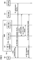
- the attach procedure is shown in Figure 3 .
- the DeNB and the MR exchange messages of a RRC connection setup (step 1).
- the RN's MME exchanges messages with the RN's HSS as well as the MR for NAS attach, authentication, and so on (step 2a, 2b).
- the DeNB can exchange messages with the RN's MME as well as internally between the S-GW and the P-GW functionalities (242a, 242b) for creating a GTP-C session (step 3a, 3b).
- Creating a GTP-C session can also be omitted. Then, messages are exchanged between the MR and the DeNB for a RRC connection configuration (4a) and between the DeNB and the RN's MME for an interface (S1) context setup (4b).
- MR Mobile Relay
- Handover (HO) success rate can be improved via Mobile Relay.
- the MR's gateway functionalities (P-GW and S-GW) are collocated in the DeNB.
- P-GW and S-GW gateway functionalities
- the MR When the MR is handovered to another DeNB, it needs to relocate the gateway functionalities to the target DeNB. But this is not supported by current 3GPP LTE standard, thus is causing an issue for the PDN connection that is using these gateway functionalities in the DeNB.
- the UE context in the P-GW is removed when the PDN connection is disconnected.
- a method is required to relocate the gateway functionalities (GW) from the source DeNB to target DeNB, and, in addition, release the context related to the gateway functionalities in the source DeNB after the mobile relay has handovered to the target DeNB.
- GW gateway functionalities
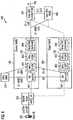
- a network system 400 supporting the relocation of the gateway functionalities according to Figure 1 is shown in Figure 4 .
- a new S1-U interface is added between the DeNBs, in detail, the eNB function 451 in target DeNB have S1-U interface with the S-GW function 442 in source DeNB.
- the DeNBs 104 and 105 provides a S-GW functionalities 442, 452 and P-GW functionalities 443, 453 for the mobile relay node 103.
- optional relay gateways 444, 454 can be provided.
- the further UE 106 can be coupled with the DeNBs via a S-GW/P-GW 461 being managed by a UE's MME 462.
- the DeNB function part 441 of the source DeNB 104 and the DeNB function part 451 of the target DeNB can communicate via a X2 interface.
- the DeNBs can exchange messages for determining whether the target base station or DeNB 105 can support the mobile relay node 103.
- the message exchange is shown in Figure 6 .
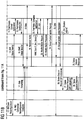
- Figure 7 shows a message flow diagram for the handover of the mobile relay node, also called X2 handover (HO) for the mobile relay node as an X2 interface may be used.
- HO handover
- a tunnel endpoint identifier (TEID) is assigned by the receiving end of the GTP tunnel to uniquely identify a tunnel endpoint in the receiving end side of a GTP tunnel.
- a Full Qualified TEID (F-TEID) contains the IP address of the receiving end of the GTP tunnel and the TEID.
- the shown call flow may provide the following enhancements to current X2 HO procedure as defined in 3GPP Rel-10.
- Step 1 By knowing the target eNB supports the MR, the source DeNB sends HO Request (Req) message to target DeNB.
- the HO Req message indicates this is for MR, and includes additional context information for all connected UEs.
- this information can consist at least of 'eNB/MME UE S1AP ID' and the 'GTP-U F-TEID' used by the MR and source DeNB for the communication between the MR and the source DeNB, and by the source DeNB for the communication between the source DeNB and the UE's MME/S-GW.
- the exchanged information from source to target DeNB may not be restricted to the lists of the old 'eNB/MME UE S1AP ID' and 'GTP-U F-TEID' as they were used by the source side, but may also contain further information from the source side (source DeNB and/or MR) like the list of E-RAB IDs of the UEs that are connected to the MR and corresponding QoS information, e.g. the Quality Class Indicator (QCI) or even the complete UE specific context that is stored at the source DeNB for each of the UEs that are connected to the MR.
- QCI Quality Class Indicator
- Step 2 The target DeNB replies with the HO Req Ack message.
- the message includes additional context information for assigned for the UEs.
- the information includes the S1 AP IDs, S1-U F-TEIDs, etc.
- the target DeNB may not be able to use the same S1AP IDs and S1-U F-TEIDs as the source DeNB, because they are required to be unique in the DeNB and the target DeNB may already use the values, e.g. for the communication with an MR that is already being served by the target DeNB when the new MR is approaching. Thus these IDs can only be determined by the target DeNB.
- the target DeNB can already reserve and inform the source DeNB about the reserved IDs when returning the corresponding handover preparation acknowledge message.
- the exchanged information from the target to source side may not be restricted to the list of the 'MME UE S1AP ID' and 'GTP-U UL F-TEID' information, but may additionally consist of information related to the UEs connected to MR like E-RABs-Admitted-List, E-RABs-NotAdmitted-List or the served globally unique MME IDs (GUMMEIs).
- Step 3 The source DeNB sends the updated context information for CONNECTED UEs to the MR.
- This can be new IEs in RRC message, or new RRC message, or new S1/X2 message.
- the new DeNB needs to convey the updated context information to MR via new IEs in RRC message, or new RRC message, or new S1/X2 message.
- New information elements may be added to the HO preparation messages from the source DeNB to the target DeNB (Step 1).
- the source DeNB provides the lists of 'eNB/MME UE S1AP ID' and 'GTP-U F-TEID' values as they are used by the MR and source DeNB for the communication between the MR and the source DeNB, and by the source DeNB for the communication between the source DeNB and the UE's MME/S-GW.
- the target DeNB then returns this list, but for each of the received values that needs to be replaced, the target DeNB determines and adds a replacement value that has to be used by the MR for the S1 communication over the Un interface to the target DeNB.
- Step 2 The latter requires corresponding enhancements to the HO preparation messages in the direction from target DeNB to source DeNB (Step 2).
- Other possible information to be exchanged as listed in the previous paragraph also may require corresponding enhancements (e.g. IEs) if these is added to existing messages.
- a new message to the MR is sent (Step 3) in order to transfer the information being received by the target DeNB.
- This new message might be sent by the source DeNB after it has decided which DeNB is the selected target DeNB (e.g. for the case that the source DeNB has prepared more than one target DeNBs for the handover of the MR) and before it sends the RRCConnReconfiguration message to the MR (Step 4).
- This new message can be an S1 or X2 message or even a new RRC message or a new IE in the RRCConnReconfiguration message.
- the existing RRCConnReconfiguration message and the new message may be combined into one new message.
- steps 5 and 6 the SN status is transferred and data forwarding is started.
- Step 7 After MR connects to the target DeNB, the UL and DL path as shown in the system 800 of Figure 8 are:
- Step 8 The target DeNB sends Path Switch Request message to MR's MME to inform that the MR has changed cell.
- the Path Switch Request message includes the IP address for the S-GW functionality collocated in target DeNB.
- Another alternative is to enhance the DNS procedure to retrieve the S-GW address (described later). When use the enhanced DNS procedure, there is no need for Path Switch Request message to include the address of the S-GW functionality.
- Step 9 MR's MME knows that this is an X2 HO for a MR, so it relocate the MR's gateway functionalities (S-GW/P-GW) from the source DeNB to target DeNB by sending a first Create Session Request message to the S-GW functionality collocated in the target DeNB using the S-GW functionalities' IP address received in Step 8.
- the Create Session Request message also indicates that this message is for MR's gateways (S-GW/P-GW) relocation.
- the Create Session Request message includes the GTP-U DL F-TEID assigned by the Target DeNB and triggers that the S-GW functionality sends the Create Session Request message to the P-GW functionality collocated in target DeNB. This message is different to the one currently used for X2 HO with S-GW relocation.
- Step 10 Upon the reception of Create Session Request message indicating this is for MR's gateway (S-GW/P-GW) relocation, the S-GW functionality sends the Create Session Request message to the collocated P-GW functionality.
- the message includes the S5-U S-GW F-TEID.
- Step 11 The P-GW returns the Create Session Response message including the S5-U P-GW F-TEID.
- Step 12 Upon the reception of the Create Session Response message, the MME starts a timer T_Del_session.
- Step 13 Upon the reception of the Path Switch Request Acknowledge message, the target DeNB can route the UL data via the collocated gateway functionalities (S-GW/P-GVV), i.e. MR ⁇ eNB function in target DeNB ⁇ S-GW/P-GW functionalities collocated in target DeNB ⁇ UE's S-GW (as shown in the system 900 of Figure 9 )
- S-GW/P-GVV collocated gateway functionalities
- Steps 15-18 Messages are exchanged for updating the group context between the UE's MME and the eNB function of the target DeNB. After Step 18, the UL and DL path are as shown in the system 1000 of Figure 10 , i.e. all paths are switched to the target DeNB.
- Step 19 When the timer T_Del_session has expired, MME releases the bearers/contexts in the S-GW functionality collocated in the source DeNB by sending a Delete Session Request message to the S-GW functionality.
- the message includes the "MR indication" that indicates to the S-GW functionality to initiate a delete procedure towards the P-GW functionality.
- Step 20 Upon detection of the "MR indication" in the received Delete Session Request message, the S-GW functionality sends the Delete Session Request message with the "MR indication" to the P-GW functionality.
- Step 21 The P-GW functionality acknowledges with Delete Session Response message.
- the P-GW functionality removes the context associated with the handovered MR.
- Step 22 The S-GW functionality acknowledges with Delete Session Response message.
- the S-GW functionality removes the context associated with the MR.
- a S1 handover for the mobile relay node is shown.
- S1 refers to the S1 interface.
- the management of the mobile relay node is transferred from one management unit to another management unit.
- the described call flow has following enhancements to current S1 HO procedure defined in 3GPP Rel-10:
- Step 1 The DeNB knows whether the target eNB supports Mobile Relay.
- the source DeNB initiates the S1 HO preparation procedure.
- the HO Req message indicates this is for MR, and includes additional context information for all CONNECTED UEs.
- this information consists at least of 'eNB/MME UE S1AP ID' and the 'GTP-U F-TEID' used by the MR and source DeNB for the communication between the MR and the source DeNB, and by the source DeNB for the communication between the source DeNB and the UE's MME/S-GW.
- the exchanged information from source to target DeNB may not be restricted to the lists of the old 'eNB/MME UE S1AP ID' and 'GTP-U F-TEID' as they were used by the source side, but may also contain further information from the source side (source DeNB and/or MR) like the list of E-RAB IDs of the UEs that are connected to the MR and corresponding QoS information, e.g. the Quality Class Indicator (QCI) or even the complete UE specific context that is stored at the source DeNB for each of the UEs that are connected to the MR.
- QCI Quality Class Indicator
- Step 2 The MR's source MME selects the target MME based on the target DeNB's TAI, eNB ID, and the indication whether the target MME supports MR. Another option is to reuse the current DNS procedure, but create a separate DNS database only to be used for MR's MME/S-GW selection.
- the MR's source MME sends a Forward Relocation Request message to target MME. The message indicates this is for MR.
- the message also contains the additional context information for CONNECTED UEs, which is received from Source DeNB.
- Step 3 Upon the reception of the enhanced Forward Relocation Request message, the target MME uses an enhanced DNS procedure to retrieve the IP address for the S-GW functionality collocated in target DeNB. The target MME then send Create Session Request message indicating the relocation of MR's gateway functionalities (S-GW/P-GW) to the S-GW functionality collocated in target DeNB, and trigger the S-GW functionality to send the Create Session Request message to the P-GW functionality collocated in target DeNB.
- S-GW/P-GW MR's gateway functionalities
- Step 4 Upon the reception of Create Session Request message indicating this is for MR's gateways functionality (S-GW/P-GW) relocation, the S-GW functionality sends the Create Session Request message to the collocated P-GW functionality.
- the Create Session Request message includes the GTP-U DL F-TEID assigned by the Target DeNB.
- Step 5 The P-GW returns the Create Session Response message including the S5-U P-GWF-TEID.
- Step 6 The S-GW functionality acknowledges with Create Session Response message.
- Step 7 The target MME sends HO Req to target DeNB.
- the HO Req message indicates this is for MR, so the target DeNB can assign MR higher priority during resource reservation, e.g. pre-empt the resource used by a normal UE.
- the message contains additional context information received from source MME.
- Step 8 The target DeNB reply with the HO Req Ack message.
- the message includes additional context information for assigned for the UEs.
- the information includes the S1 AP IDs, S1-U F-TEIDs, etc.
- the target DeNB may not be able to use the same S1AP IDs and S1-U F-TEIDs as the source DeNB, because they are required to be unique in the DeNB and the target DeNB may already use the values, e.g. for the communication with an MR that is already being served by the target DeNB when the new MR is approaching. Thus these IDs can only be determined by the target DeNB.
- the target DeNB can already reserve and inform the source DeNB about the reserved IDs when returning the corresponding handover preparation acknowledge message.
- the exchanged information from the target to source side may not be restricted to the list of the 'MME UE S1AP ID' and 'GTP-U UL F-TEID' information, but may additionally consist of information related to the UEs connected to MR like E-RABs-Admitted-List, E-RABs-NotAdmitted-List or the served globally unique MME IDs (GUMMEIs).
- Step 9 The target MME sends Forward Relocation Response message to source MME.
- the message also contains the updated context information received from target DeNB.
- Step 10 The source MME send HO Req Ack message to source DeNB.
- the message includes the updated context information received from target MME.
- Step 11 The source DeNB send the updated context information for CONNECTED UEs to the MR.
- This can be new IEs in RRC message, or new RRC message, or new S1/X2 message.
- the new DeNB might need to convey the updated context information to MR.
- the source DeNB provides the lists of 'eNB/MME UE S1AP ID' and 'GTP-U F-TEID' values as they are used by the MR and source DeNB for the communication between the MR and the source DeNB, and by the source DeNB for the communication between the source DeNB and the UE's MME/S-GW.
- IE new information elements
- the target DeNB then returns this list, but for each of the received values that needs to be replaced the target DeNB determines and adds a replacement value that has to be used by the MR for the S1 communication over the Un interface to the target DeNB.
- the latter requires corresponding enhancements to the HO preparation messages in the direction from target DeNB to source DeNB (Step 8).
- Other possible information to be exchanged as listed in the previous paragraph also would require corresponding enhancements (e.g. IEs) if these is added to existing messages.
- a new message to the MR is needed (Step 11) in order to the transfer the information being received from the target DeNB.
- This new message has to be sent by the source DeNB after it has decided which DeNB is the selected target DeNB and before it sends the RRCConnReconfiguration message to the MR (Step 12).
- This message can be an S1 or X2 message or even a new RRC message or a new IE in the RRCConnReconfiguration message.
- the existing RRCConnReconfiguration message and the new message may be combined into one new message.
- Steps 13 to 19 Messages are exchanged for transferring status information and data.
- Step 20 Upon receipt of the Forward Relocation Complete Notification message, the source MME starts a timer T_Del_Session.
- Step 24-25 After the Group Context Update procedure is completed, the DL data can be routed via UE's S-GW ⁇ P-GW functionality collocated in target DeNB ⁇ S-GWfunctionality collocated in target DeNB ⁇ eNB function in target DeNB ⁇ MR.
- Step 26 When the timer T_Del_session has expired, MME releases the bearers/contexts in the S-GW functionality collocated in the source DeNB by sending a Delete Session Request message to the S-GW functionaltiy.
- the message includes the "MR indication" that indicates to the S-GW functionaltiy to initiate a delete procedure towards the P-GW functionality.
- Step 27 Upon see the "MR indication" in the received Delete Session Request message, the S-GW functionality sends the Delete Session Request message with the "MR indication" to the P-GW functionality.
- Step 28 The P-GW functionality acknowledges with Delete Session Response message.
- the P-GW functionality removes the context associated with the MR.
- Step 29 The S-GW functionality acknowledges with Delete Session Response message.
- the S-GW functionality removes the context associated with the MR.
- a management unit as disclosed herein is not limited to dedicated entities as described in some embodiments. Rather, the herein disclosed subject matter may be implemented in various ways in various locations in the communication network while still providing the desired functionality.
- any suitable entity e.g. components, units and devices
- e.g. the configuration unit are at least in part provided in the form of respective computer programs which enable a processor device to provide the functionality of the respective entities as disclosed herein.
- any suitable entity disclosed herein may be provided in hardware.
- some entities may be provided in software while other entities are provided in hardware.
- any entity disclosed herein e.g. components, units and devices
- the herein disclosed subject matter may be implemented in various ways and with various granularity on device level while still providing the desired functionality.
- a separate entity e.g. a software module, a hardware module or a hybrid module
- an entity e.g. a software module, a hardware module or a hybrid module (combined software/hardware module) is configured for providing two or more functions as disclosed herein.
Landscapes
- Engineering & Computer Science (AREA)
- Computer Networks & Wireless Communication (AREA)
- Signal Processing (AREA)
- Mobile Radio Communication Systems (AREA)
Claims (13)
- Un procédé de transfert d'un noeud relais mobile (103) d'une station de base source (104) vers une station de base cible (105), dans lequel un équipement d'utilisateur (102) est adapté de façon à communiquer avec un autre équipement d'utilisateur (106) au moyen d'un trajet de communication par l'intermédiaire du noeud relais mobile et de la station de base source au moyen d'une première fonctionnalité de passerelle (140) de la station de base source, et dans lequel une unité de gestion (101) est adaptée de façon à gérer le trajet de communication,
le procédé comprenant
la préparation, par l'unité de gestion (101), d'un transfert du noeud relais mobile (103) de la station de base source (104) à la station de base cible (105),
l'attribution, par l'unité de gestion (101), de ressources dans la station de base cible (105) pour la fourniture d'une deuxième fonctionnalité de passerelle (150) pour un autre trajet de communication pour l'équipement d'utilisateur (102) par l'intermédiaire du noeud relais mobile (103) et de la station de base cible (105) à l'autre équipement d'utilisateur (106),
l'établissement, par l'unité de gestion (101), de la deuxième fonctionnalité de passerelle (150) pour l'autre trajet de communication pour l'équipement d'utilisateur (102) par l'intermédiaire du noeud relais mobile (103) et de la station de base cible (105) à l'autre équipement d'utilisateur (106), et
le transfert, par l'unité de gestion (101), du noeud relais mobile (103) de la station de base source (104) à la station de base cible (105). - Le procédé selon la revendication 1, dans lequel
l'établissement d'une fonctionnalité de passerelle comprend la relocalisation d'informations qui sont associées au noeud relais mobile (103) de la station de base source (104) à la station de base cible (105). - Le procédé selon la revendication 2, dans lequel les informations qui sont associées au noeud relais mobile (103) comprennent des informations relatives à l'équipement d'utilisateur (102) et aux autres équipements d'utilisateur qui sont raccordés au noeud relais mobile.
- Le procédé selon l'une quelconque des revendications précédentes, comprenant en outre l'établissement du trajet de communication, par l'unité de gestion (101), entre la station de base cible (105) et la première fonctionnalité de passerelle (140) dans la station de base source (104).
- Le procédé selon la revendication 4, dans lequel l'attribution de ressources comprend l'attribution de ressources qui sont associées à la deuxième fonctionnalité de passerelle (150), de façon à établir le trajet de communication entre la station de base cible (105) et la deuxième fonctionnalité de passerelle (150).
- Le procédé selon l'une quelconque des revendications précédentes, le procédé comprenant en outre la libération de ressources à l'intérieur de la station de base source (104) qui sont associées à la première fonctionnalité de passerelle (140) après le transfert.
- Le procédé selon l'une quelconque des revendications précédentes, le procédé comprenant en outre,
avant le lancement du transfert, un échange de messages entre la station de base source (104) et la station de base cible (105) de façon à déterminer si la station de base cible (105) possède la capacité de prendre en charge un noeud relais mobile. - Le procédé selon l'une quelconque des revendications précédentes, dans lequel le transfert du noeud relais mobile (103) comprend la modification du trajet de communication de la première fonctionnalité de passerelle (140) à l'autre trajet de communication de la deuxième fonctionnalité de passerelle (150).
- Le procédé selon l'une quelconque des revendications précédentes, le procédé comprenant en outre
le transfert de la gestion du noeud relais mobile (103) de l'unité de gestion (101) à une autre unité de gestion (1101). - Le procédé selon la revendication 9, dans lequel le transfert de la gestion du noeud relais mobile (103) comprend l'envoi d'informations qui sont associées aux fonctionnalités de passerelle pour le noeud relais mobile (103) de l'unité de gestion (101) à l'autre unité de gestion (1101).
- Le procédé selon la revendication 10, comprenant en outre l'établissement, par l'autre unité de gestion (1101), d'un trajet de communication pour l'équipement d'utilisateur (102) par l'intermédiaire de la deuxième fonctionnalité de passerelle (150).
- Une unité de gestion (101) de transfert d'un noeud relais mobile (103) d'une station de base source (104) à une station de base cible (105), dans laquelle un équipement d'utilisateur (102) est adapté de façon à communiquer avec un autre équipement d'utilisateur (106) au moyen d'un trajet de communication par l'intermédiaire du noeud relais mobile (103) et de la station de base source (104) au moyen d'une première fonctionnalité de passerelle (140) de la station de base source (104), et dans laquelle l'unité de gestion (101) est adaptée de façon à gérer le trajet de communication, caractérisé en ce que l'unité de gestion (101) comprend
une unité de commande qui est adaptée de façon à préparer un transfert du noeud relais mobile de la station de base source à la station de base cible, qui est adaptée de façon à attribuer des ressources dans la station de base cible pour la fourniture d'une deuxième fonctionnalité de passerelle pour un autre trajet de communication pour l'équipement d'utilisateur par l'intermédiaire du noeud relais mobile et de la station de base cible à l'autre équipement d'utilisateur, qui est adaptée de façon à établir la deuxième fonctionnalité de passerelle pour l'autre trajet de communication pour l'équipement d'utilisateur par l'intermédiaire du noeud relais mobile et de la station de base cible à l'autre équipement d'utilisateur, et qui est adaptée de façon à transférer le noeud relais mobile de la station de base source à la station de base cible. - Un système de réseau (100) destiné au transfert d'un noeud relais mobile (103) d'une station de base source (104) à une station de base cible (105), dans lequel un équipement d'utilisateur (102) est adapté de façon à communiquer avec un autre équipement d'utilisateur (106) au moyen d'un trajet de communication par l'intermédiaire du noeud relais mobile (103) et de la station de base source (104) au moyen d'une première fonctionnalité de passerelle (140) de la station de base source (104), le système de réseau comprenant une unité de gestion (101) selon la revendication 12.
Applications Claiming Priority (1)
| Application Number | Priority Date | Filing Date | Title |
|---|---|---|---|
| PCT/EP2011/071033 WO2013075755A1 (fr) | 2011-11-25 | 2011-11-25 | Procédé de transfert d'un nœud de relais mobile |
Publications (2)
| Publication Number | Publication Date |
|---|---|
| EP2783531A1 EP2783531A1 (fr) | 2014-10-01 |
| EP2783531B1 true EP2783531B1 (fr) | 2016-02-24 |
Family
ID=45065889
Family Applications (1)
| Application Number | Title | Priority Date | Filing Date |
|---|---|---|---|
| EP11790598.4A Not-in-force EP2783531B1 (fr) | 2011-11-25 | 2011-11-25 | Procédé de transfért d'un noed mobile de rélais |
Country Status (3)
| Country | Link |
|---|---|
| US (1) | US20150296424A1 (fr) |
| EP (1) | EP2783531B1 (fr) |
| WO (1) | WO2013075755A1 (fr) |
Families Citing this family (13)
| Publication number | Priority date | Publication date | Assignee | Title |
|---|---|---|---|---|
| CN103188650B (zh) * | 2011-12-28 | 2016-03-23 | 电信科学技术研究院 | 网关选择方法和设备 |
| CN103220816B (zh) * | 2012-01-19 | 2018-05-15 | 北京三星通信技术研究有限公司 | 一种rn和核心网之间的接口建立和通信方法 |
| US9544825B2 (en) * | 2012-03-13 | 2017-01-10 | Lg Electronics Inc. | Method and apparatus for determining handover of user equipments attached to mobile relay nodes in wireless communication system |
| GB2503942A (en) * | 2012-07-13 | 2014-01-15 | Nec Corp | Mobile relay node handover in a wireless communication system |
| US20150146596A1 (en) * | 2012-08-03 | 2015-05-28 | Lg Electronics Inc. | Method and Apparatus for Transmitting Indication in Wireless Communication System |
| US9560679B2 (en) * | 2013-05-24 | 2017-01-31 | Telefonaktiebolaget Lm Ericsson (Publ) | Method, apparatus, system, computer program and computer program products for providing a PLMN identifier to a node of a RAN |
| US9992721B2 (en) * | 2013-12-27 | 2018-06-05 | Futurewei Technologies, Inc. | System and method for distributed mobility management with GPRS tunneling protocol |
| EP3142414B1 (fr) * | 2014-05-30 | 2018-11-07 | Huawei Technologies Co., Ltd. | Procédé et dispositif de changement de chemin de service |
| US9961562B2 (en) * | 2015-06-15 | 2018-05-01 | Motorola Solutions, Inc. | System and method for extending coverage of a communication network |
| US11089519B2 (en) * | 2016-04-13 | 2021-08-10 | Qualcomm Incorporated | Migration of local gateway function in cellular networks |
| US11184936B2 (en) * | 2017-05-05 | 2021-11-23 | Lg Electronics Inc. | Method and apparatus for managing a bearer configuration of a relay user equipment |
| US11503471B2 (en) * | 2019-03-25 | 2022-11-15 | Fortinet, Inc. | Mitigation of DDoS attacks on mobile networks using DDoS detection engine deployed in relation to an evolve node B |
| CN113676963B (zh) * | 2020-05-14 | 2023-03-14 | 展讯通信(上海)有限公司 | 切换方法及装置、存储介质、终端 |
Citations (1)
| Publication number | Priority date | Publication date | Assignee | Title |
|---|---|---|---|---|
| US20120252355A1 (en) * | 2011-04-04 | 2012-10-04 | Qualcomm Incorporated | Apparatus and method for handing over relays |
Family Cites Families (8)
| Publication number | Priority date | Publication date | Assignee | Title |
|---|---|---|---|---|
| CN101262269B (zh) * | 2007-03-05 | 2012-08-29 | 华为技术有限公司 | 一种群节点切换方法及通信系统 |
| US9084283B2 (en) * | 2008-11-19 | 2015-07-14 | Qualcomm Incorporated | Peer-to-peer communication using a wide area network air interface |
| US20100329216A1 (en) * | 2009-06-29 | 2010-12-30 | Yu-Chih Jen | Method of Handling Mobile Device Mobility and Related Communication Device |
| US9125133B2 (en) * | 2009-08-12 | 2015-09-01 | Qualcomm Incorporated | Method and apparatus for relay backhaul design in a wireless communication system |
| US8611333B2 (en) * | 2009-08-12 | 2013-12-17 | Qualcomm Incorporated | Systems and methods of mobile relay mobility in asynchronous networks |
| US9210622B2 (en) * | 2009-08-12 | 2015-12-08 | Qualcomm Incorporated | Method and apparatus for relay backhaul design in a wireless communication system |
| US8406192B2 (en) * | 2009-10-02 | 2013-03-26 | Research In Motion Limited | Handover mechanisms with synchronous PDCP protocol under various relay architectures |
| US9031039B2 (en) * | 2010-05-14 | 2015-05-12 | Lg Electronics Inc. | Method and apparatus for performing handover procedure in wireless communication system |
-
2011
- 2011-11-25 EP EP11790598.4A patent/EP2783531B1/fr not_active Not-in-force
- 2011-11-25 US US14/364,906 patent/US20150296424A1/en not_active Abandoned
- 2011-11-25 WO PCT/EP2011/071033 patent/WO2013075755A1/fr active Application Filing
Patent Citations (2)
| Publication number | Priority date | Publication date | Assignee | Title |
|---|---|---|---|---|
| US20120252355A1 (en) * | 2011-04-04 | 2012-10-04 | Qualcomm Incorporated | Apparatus and method for handing over relays |
| WO2012138736A1 (fr) * | 2011-04-04 | 2012-10-11 | Qualcomm Incorporated | Appareil et procédé de transfert de relais |
Also Published As
| Publication number | Publication date |
|---|---|
| WO2013075755A1 (fr) | 2013-05-30 |
| US20150296424A1 (en) | 2015-10-15 |
| EP2783531A1 (fr) | 2014-10-01 |
Similar Documents
| Publication | Publication Date | Title |
|---|---|---|
| EP2783531B1 (fr) | Procédé de transfért d'un noed mobile de rélais | |
| US10356665B2 (en) | Source base station gateway (GW) for releasing resources associated with a mobile device | |
| US10736009B2 (en) | Handover method and apparatus | |
| US9532290B2 (en) | Handover with mobile relays | |
| JP6005816B2 (ja) | フェムトセルを含む無線通信ネットワークにおけるローカルipアクセスサポート方法及び装置 | |
| EP3547793B1 (fr) | Procédé et dispositif de gestion d'interface permettant de prendre en charge un interfonctionnement lte/nr dans un système de communication sans fil | |
| CN106162771B (zh) | 一种小小区系统中不同MeNB间切换的方法及设备 | |
| CN112911726B (zh) | 一种用户平面承载建立的方法及装置 | |
| CN104994575B (zh) | 更新用户设备位置信息的方法 | |
| US8687592B2 (en) | Method for switching session of user equipment in wireless communication system and system employing the same | |
| US9807667B2 (en) | Method for relocating gateway, mobile management entity and host base station | |
| US10560837B2 (en) | Method and apparatus for supporting standalone local gateway service for dual connectivity in wireless communication system | |
| CN108184249B (zh) | 回程链路的信息传输方法及系统、代理设备、接入设备 | |
| KR20170016974A (ko) | 무선 통신 시스템에서 이중 연결을 위한 로컬 게이트웨이 서비스를 지원하는 방법 및 장치 | |
| WO2014044117A1 (fr) | Procédé de relocalisation de passerelle et entité de gestion de mobilité | |
| CN103974228A (zh) | 一种实现x2代理的方法及系统 | |
| CN102892153A (zh) | 一种中继节点切换中释放用户终端信息的方法和系统 |
Legal Events
| Date | Code | Title | Description |
|---|---|---|---|
| PUAI | Public reference made under article 153(3) epc to a published international application that has entered the european phase |
Free format text: ORIGINAL CODE: 0009012 |
|
| 17P | Request for examination filed |
Effective date: 20140625 |
|
| AK | Designated contracting states |
Kind code of ref document: A1 Designated state(s): AL AT BE BG CH CY CZ DE DK EE ES FI FR GB GR HR HU IE IS IT LI LT LU LV MC MK MT NL NO PL PT RO RS SE SI SK SM TR |
|
| DAX | Request for extension of the european patent (deleted) | ||
| RIC1 | Information provided on ipc code assigned before grant |
Ipc: H04W 36/00 20090101AFI20150710BHEP Ipc: H04W 88/04 20090101ALN20150710BHEP |
|
| GRAP | Despatch of communication of intention to grant a patent |
Free format text: ORIGINAL CODE: EPIDOSNIGR1 |
|
| INTG | Intention to grant announced |
Effective date: 20150924 |
|
| GRAS | Grant fee paid |
Free format text: ORIGINAL CODE: EPIDOSNIGR3 |
|
| GRAA | (expected) grant |
Free format text: ORIGINAL CODE: 0009210 |
|
| AK | Designated contracting states |
Kind code of ref document: B1 Designated state(s): AL AT BE BG CH CY CZ DE DK EE ES FI FR GB GR HR HU IE IS IT LI LT LU LV MC MK MT NL NO PL PT RO RS SE SI SK SM TR |
|
| REG | Reference to a national code |
Ref country code: GB Ref legal event code: FG4D |
|
| REG | Reference to a national code |
Ref country code: CH Ref legal event code: EP |
|
| REG | Reference to a national code |
Ref country code: AT Ref legal event code: REF Ref document number: 777285 Country of ref document: AT Kind code of ref document: T Effective date: 20160315 |
|
| REG | Reference to a national code |
Ref country code: IE Ref legal event code: FG4D |
|
| REG | Reference to a national code |
Ref country code: DE Ref legal event code: R096 Ref document number: 602011023462 Country of ref document: DE |
|
| REG | Reference to a national code |
Ref country code: LT Ref legal event code: MG4D |
|
| REG | Reference to a national code |
Ref country code: NL Ref legal event code: MP Effective date: 20160224 |
|
| REG | Reference to a national code |
Ref country code: AT Ref legal event code: MK05 Ref document number: 777285 Country of ref document: AT Kind code of ref document: T Effective date: 20160224 |
|
| PG25 | Lapsed in a contracting state [announced via postgrant information from national office to epo] |
Ref country code: HR Free format text: LAPSE BECAUSE OF FAILURE TO SUBMIT A TRANSLATION OF THE DESCRIPTION OR TO PAY THE FEE WITHIN THE PRESCRIBED TIME-LIMIT Effective date: 20160224 Ref country code: GR Free format text: LAPSE BECAUSE OF FAILURE TO SUBMIT A TRANSLATION OF THE DESCRIPTION OR TO PAY THE FEE WITHIN THE PRESCRIBED TIME-LIMIT Effective date: 20160525 Ref country code: FI Free format text: LAPSE BECAUSE OF FAILURE TO SUBMIT A TRANSLATION OF THE DESCRIPTION OR TO PAY THE FEE WITHIN THE PRESCRIBED TIME-LIMIT Effective date: 20160224 Ref country code: ES Free format text: LAPSE BECAUSE OF FAILURE TO SUBMIT A TRANSLATION OF THE DESCRIPTION OR TO PAY THE FEE WITHIN THE PRESCRIBED TIME-LIMIT Effective date: 20160224 Ref country code: IT Free format text: LAPSE BECAUSE OF FAILURE TO SUBMIT A TRANSLATION OF THE DESCRIPTION OR TO PAY THE FEE WITHIN THE PRESCRIBED TIME-LIMIT Effective date: 20160224 Ref country code: NO Free format text: LAPSE BECAUSE OF FAILURE TO SUBMIT A TRANSLATION OF THE DESCRIPTION OR TO PAY THE FEE WITHIN THE PRESCRIBED TIME-LIMIT Effective date: 20160524 |
|
| PG25 | Lapsed in a contracting state [announced via postgrant information from national office to epo] |
Ref country code: NL Free format text: LAPSE BECAUSE OF FAILURE TO SUBMIT A TRANSLATION OF THE DESCRIPTION OR TO PAY THE FEE WITHIN THE PRESCRIBED TIME-LIMIT Effective date: 20160224 Ref country code: AT Free format text: LAPSE BECAUSE OF FAILURE TO SUBMIT A TRANSLATION OF THE DESCRIPTION OR TO PAY THE FEE WITHIN THE PRESCRIBED TIME-LIMIT Effective date: 20160224 Ref country code: RS Free format text: LAPSE BECAUSE OF FAILURE TO SUBMIT A TRANSLATION OF THE DESCRIPTION OR TO PAY THE FEE WITHIN THE PRESCRIBED TIME-LIMIT Effective date: 20160224 Ref country code: SE Free format text: LAPSE BECAUSE OF FAILURE TO SUBMIT A TRANSLATION OF THE DESCRIPTION OR TO PAY THE FEE WITHIN THE PRESCRIBED TIME-LIMIT Effective date: 20160224 Ref country code: LV Free format text: LAPSE BECAUSE OF FAILURE TO SUBMIT A TRANSLATION OF THE DESCRIPTION OR TO PAY THE FEE WITHIN THE PRESCRIBED TIME-LIMIT Effective date: 20160224 Ref country code: PL Free format text: LAPSE BECAUSE OF FAILURE TO SUBMIT A TRANSLATION OF THE DESCRIPTION OR TO PAY THE FEE WITHIN THE PRESCRIBED TIME-LIMIT Effective date: 20160224 Ref country code: PT Free format text: LAPSE BECAUSE OF FAILURE TO SUBMIT A TRANSLATION OF THE DESCRIPTION OR TO PAY THE FEE WITHIN THE PRESCRIBED TIME-LIMIT Effective date: 20160624 Ref country code: LT Free format text: LAPSE BECAUSE OF FAILURE TO SUBMIT A TRANSLATION OF THE DESCRIPTION OR TO PAY THE FEE WITHIN THE PRESCRIBED TIME-LIMIT Effective date: 20160224 |
|
| PG25 | Lapsed in a contracting state [announced via postgrant information from national office to epo] |
Ref country code: EE Free format text: LAPSE BECAUSE OF FAILURE TO SUBMIT A TRANSLATION OF THE DESCRIPTION OR TO PAY THE FEE WITHIN THE PRESCRIBED TIME-LIMIT Effective date: 20160224 Ref country code: DK Free format text: LAPSE BECAUSE OF FAILURE TO SUBMIT A TRANSLATION OF THE DESCRIPTION OR TO PAY THE FEE WITHIN THE PRESCRIBED TIME-LIMIT Effective date: 20160224 |
|
| REG | Reference to a national code |
Ref country code: DE Ref legal event code: R097 Ref document number: 602011023462 Country of ref document: DE |
|
| PG25 | Lapsed in a contracting state [announced via postgrant information from national office to epo] |
Ref country code: CZ Free format text: LAPSE BECAUSE OF FAILURE TO SUBMIT A TRANSLATION OF THE DESCRIPTION OR TO PAY THE FEE WITHIN THE PRESCRIBED TIME-LIMIT Effective date: 20160224 Ref country code: RO Free format text: LAPSE BECAUSE OF FAILURE TO SUBMIT A TRANSLATION OF THE DESCRIPTION OR TO PAY THE FEE WITHIN THE PRESCRIBED TIME-LIMIT Effective date: 20160224 Ref country code: SK Free format text: LAPSE BECAUSE OF FAILURE TO SUBMIT A TRANSLATION OF THE DESCRIPTION OR TO PAY THE FEE WITHIN THE PRESCRIBED TIME-LIMIT Effective date: 20160224 Ref country code: SM Free format text: LAPSE BECAUSE OF FAILURE TO SUBMIT A TRANSLATION OF THE DESCRIPTION OR TO PAY THE FEE WITHIN THE PRESCRIBED TIME-LIMIT Effective date: 20160224 |
|
| PG25 | Lapsed in a contracting state [announced via postgrant information from national office to epo] |
Ref country code: BE Free format text: LAPSE BECAUSE OF FAILURE TO SUBMIT A TRANSLATION OF THE DESCRIPTION OR TO PAY THE FEE WITHIN THE PRESCRIBED TIME-LIMIT Effective date: 20160224 |
|
| PLBE | No opposition filed within time limit |
Free format text: ORIGINAL CODE: 0009261 |
|
| STAA | Information on the status of an ep patent application or granted ep patent |
Free format text: STATUS: NO OPPOSITION FILED WITHIN TIME LIMIT |
|
| 26N | No opposition filed |
Effective date: 20161125 |
|
| PG25 | Lapsed in a contracting state [announced via postgrant information from national office to epo] |
Ref country code: SI Free format text: LAPSE BECAUSE OF FAILURE TO SUBMIT A TRANSLATION OF THE DESCRIPTION OR TO PAY THE FEE WITHIN THE PRESCRIBED TIME-LIMIT Effective date: 20160224 Ref country code: BG Free format text: LAPSE BECAUSE OF FAILURE TO SUBMIT A TRANSLATION OF THE DESCRIPTION OR TO PAY THE FEE WITHIN THE PRESCRIBED TIME-LIMIT Effective date: 20160524 |
|
| REG | Reference to a national code |
Ref country code: CH Ref legal event code: PL |
|
| PG25 | Lapsed in a contracting state [announced via postgrant information from national office to epo] |
Ref country code: CH Free format text: LAPSE BECAUSE OF NON-PAYMENT OF DUE FEES Effective date: 20161130 Ref country code: LI Free format text: LAPSE BECAUSE OF NON-PAYMENT OF DUE FEES Effective date: 20161130 |
|
| REG | Reference to a national code |
Ref country code: IE Ref legal event code: MM4A |
|
| REG | Reference to a national code |
Ref country code: FR Ref legal event code: ST Effective date: 20170731 |
|
| PG25 | Lapsed in a contracting state [announced via postgrant information from national office to epo] |
Ref country code: LU Free format text: LAPSE BECAUSE OF NON-PAYMENT OF DUE FEES Effective date: 20161130 |
|
| PG25 | Lapsed in a contracting state [announced via postgrant information from national office to epo] |
Ref country code: FR Free format text: LAPSE BECAUSE OF NON-PAYMENT OF DUE FEES Effective date: 20161130 |
|
| PG25 | Lapsed in a contracting state [announced via postgrant information from national office to epo] |
Ref country code: IE Free format text: LAPSE BECAUSE OF NON-PAYMENT OF DUE FEES Effective date: 20161125 |
|
| PG25 | Lapsed in a contracting state [announced via postgrant information from national office to epo] |
Ref country code: HU Free format text: LAPSE BECAUSE OF FAILURE TO SUBMIT A TRANSLATION OF THE DESCRIPTION OR TO PAY THE FEE WITHIN THE PRESCRIBED TIME-LIMIT; INVALID AB INITIO Effective date: 20111125 |
|
| PG25 | Lapsed in a contracting state [announced via postgrant information from national office to epo] |
Ref country code: IS Free format text: LAPSE BECAUSE OF FAILURE TO SUBMIT A TRANSLATION OF THE DESCRIPTION OR TO PAY THE FEE WITHIN THE PRESCRIBED TIME-LIMIT Effective date: 20160224 Ref country code: MK Free format text: LAPSE BECAUSE OF FAILURE TO SUBMIT A TRANSLATION OF THE DESCRIPTION OR TO PAY THE FEE WITHIN THE PRESCRIBED TIME-LIMIT Effective date: 20160224 Ref country code: MC Free format text: LAPSE BECAUSE OF FAILURE TO SUBMIT A TRANSLATION OF THE DESCRIPTION OR TO PAY THE FEE WITHIN THE PRESCRIBED TIME-LIMIT Effective date: 20160224 Ref country code: CY Free format text: LAPSE BECAUSE OF FAILURE TO SUBMIT A TRANSLATION OF THE DESCRIPTION OR TO PAY THE FEE WITHIN THE PRESCRIBED TIME-LIMIT Effective date: 20160224 |
|
| PGFP | Annual fee paid to national office [announced via postgrant information from national office to epo] |
Ref country code: DE Payment date: 20180601 Year of fee payment: 7 |
|
| PG25 | Lapsed in a contracting state [announced via postgrant information from national office to epo] |
Ref country code: MT Free format text: LAPSE BECAUSE OF NON-PAYMENT OF DUE FEES Effective date: 20161125 |
|
| PG25 | Lapsed in a contracting state [announced via postgrant information from national office to epo] |
Ref country code: TR Free format text: LAPSE BECAUSE OF FAILURE TO SUBMIT A TRANSLATION OF THE DESCRIPTION OR TO PAY THE FEE WITHIN THE PRESCRIBED TIME-LIMIT Effective date: 20160224 Ref country code: AL Free format text: LAPSE BECAUSE OF FAILURE TO SUBMIT A TRANSLATION OF THE DESCRIPTION OR TO PAY THE FEE WITHIN THE PRESCRIBED TIME-LIMIT Effective date: 20160224 |
|
| PGFP | Annual fee paid to national office [announced via postgrant information from national office to epo] |
Ref country code: GB Payment date: 20180530 Year of fee payment: 7 |
|
| REG | Reference to a national code |
Ref country code: DE Ref legal event code: R119 Ref document number: 602011023462 Country of ref document: DE |
|
| GBPC | Gb: european patent ceased through non-payment of renewal fee |
Effective date: 20181125 |
|
| PG25 | Lapsed in a contracting state [announced via postgrant information from national office to epo] |
Ref country code: DE Free format text: LAPSE BECAUSE OF NON-PAYMENT OF DUE FEES Effective date: 20190601 |
|
| PG25 | Lapsed in a contracting state [announced via postgrant information from national office to epo] |
Ref country code: GB Free format text: LAPSE BECAUSE OF NON-PAYMENT OF DUE FEES Effective date: 20181125 |
|
| REG | Reference to a national code |
Ref country code: DE Ref legal event code: R081 Ref document number: 602011023462 Country of ref document: DE Owner name: WSOU INVESTMENTS, LLC, LOS ANGELES, US Free format text: FORMER OWNER: NOKIA SOLUTIONS AND NETWORKS OY, ESPOO, FI |
|
| REG | Reference to a national code |
Ref country code: GB Ref legal event code: 732E Free format text: REGISTERED BETWEEN 20200820 AND 20200826 |