EP2783146B1 - Coupling with projections having angularly oriented surface portions - Google Patents
Coupling with projections having angularly oriented surface portions Download PDFInfo
- Publication number
- EP2783146B1 EP2783146B1 EP12851307.4A EP12851307A EP2783146B1 EP 2783146 B1 EP2783146 B1 EP 2783146B1 EP 12851307 A EP12851307 A EP 12851307A EP 2783146 B1 EP2783146 B1 EP 2783146B1
- Authority
- EP
- European Patent Office
- Prior art keywords
- coupling
- pipe
- segments
- surface portion
- projections
- Prior art date
- Legal status (The legal status is an assumption and is not a legal conclusion. Google has not performed a legal analysis and makes no representation as to the accuracy of the status listed.)
- Active
Links
- 230000008878 coupling Effects 0.000 title claims description 120
- 238000010168 coupling process Methods 0.000 title claims description 120
- 238000005859 coupling reaction Methods 0.000 title claims description 120
- 238000000034 method Methods 0.000 claims description 25
- 238000003780 insertion Methods 0.000 claims description 11
- 230000037431 insertion Effects 0.000 claims description 11
- 238000005304 joining Methods 0.000 description 5
- 238000009434 installation Methods 0.000 description 4
- 239000011324 bead Substances 0.000 description 3
- 238000005452 bending Methods 0.000 description 2
- 239000012530 fluid Substances 0.000 description 2
- 239000003638 chemical reducing agent Substances 0.000 description 1
- 230000001419 dependent effect Effects 0.000 description 1
- 238000012966 insertion method Methods 0.000 description 1
- 238000011900 installation process Methods 0.000 description 1
- 238000004519 manufacturing process Methods 0.000 description 1
- 230000013011 mating Effects 0.000 description 1
- 238000005096 rolling process Methods 0.000 description 1
Images


Classifications
-
- F—MECHANICAL ENGINEERING; LIGHTING; HEATING; WEAPONS; BLASTING
- F16—ENGINEERING ELEMENTS AND UNITS; GENERAL MEASURES FOR PRODUCING AND MAINTAINING EFFECTIVE FUNCTIONING OF MACHINES OR INSTALLATIONS; THERMAL INSULATION IN GENERAL
- F16L—PIPES; JOINTS OR FITTINGS FOR PIPES; SUPPORTS FOR PIPES, CABLES OR PROTECTIVE TUBING; MEANS FOR THERMAL INSULATION IN GENERAL
- F16L17/00—Joints with packing adapted to sealing by fluid pressure
- F16L17/02—Joints with packing adapted to sealing by fluid pressure with sealing rings arranged between outer surface of pipe and inner surface of sleeve or socket
- F16L17/04—Joints with packing adapted to sealing by fluid pressure with sealing rings arranged between outer surface of pipe and inner surface of sleeve or socket with longitudinally split or divided sleeve
-
- F—MECHANICAL ENGINEERING; LIGHTING; HEATING; WEAPONS; BLASTING
- F16—ENGINEERING ELEMENTS AND UNITS; GENERAL MEASURES FOR PRODUCING AND MAINTAINING EFFECTIVE FUNCTIONING OF MACHINES OR INSTALLATIONS; THERMAL INSULATION IN GENERAL
- F16L—PIPES; JOINTS OR FITTINGS FOR PIPES; SUPPORTS FOR PIPES, CABLES OR PROTECTIVE TUBING; MEANS FOR THERMAL INSULATION IN GENERAL
- F16L21/00—Joints with sleeve or socket
- F16L21/06—Joints with sleeve or socket with a divided sleeve or ring clamping around the pipe-ends
- F16L21/065—Joints with sleeve or socket with a divided sleeve or ring clamping around the pipe-ends tightened by tangentially-arranged threaded pins
-
- F—MECHANICAL ENGINEERING; LIGHTING; HEATING; WEAPONS; BLASTING
- F16—ENGINEERING ELEMENTS AND UNITS; GENERAL MEASURES FOR PRODUCING AND MAINTAINING EFFECTIVE FUNCTIONING OF MACHINES OR INSTALLATIONS; THERMAL INSULATION IN GENERAL
- F16L—PIPES; JOINTS OR FITTINGS FOR PIPES; SUPPORTS FOR PIPES, CABLES OR PROTECTIVE TUBING; MEANS FOR THERMAL INSULATION IN GENERAL
- F16L23/00—Flanged joints
- F16L23/04—Flanged joints the flanges being connected by members tensioned in the radial plane
- F16L23/08—Flanged joints the flanges being connected by members tensioned in the radial plane connection by tangentially arranged pin and nut
-
- Y—GENERAL TAGGING OF NEW TECHNOLOGICAL DEVELOPMENTS; GENERAL TAGGING OF CROSS-SECTIONAL TECHNOLOGIES SPANNING OVER SEVERAL SECTIONS OF THE IPC; TECHNICAL SUBJECTS COVERED BY FORMER USPC CROSS-REFERENCE ART COLLECTIONS [XRACs] AND DIGESTS
- Y10—TECHNICAL SUBJECTS COVERED BY FORMER USPC
- Y10T—TECHNICAL SUBJECTS COVERED BY FORMER US CLASSIFICATION
- Y10T29/00—Metal working
- Y10T29/49—Method of mechanical manufacture
- Y10T29/49826—Assembling or joining
- Y10T29/49863—Assembling or joining with prestressing of part
- Y10T29/4987—Elastic joining of parts
- Y10T29/49872—Confining elastic part in socket
-
- Y—GENERAL TAGGING OF NEW TECHNOLOGICAL DEVELOPMENTS; GENERAL TAGGING OF CROSS-SECTIONAL TECHNOLOGIES SPANNING OVER SEVERAL SECTIONS OF THE IPC; TECHNICAL SUBJECTS COVERED BY FORMER USPC CROSS-REFERENCE ART COLLECTIONS [XRACs] AND DIGESTS
- Y10—TECHNICAL SUBJECTS COVERED BY FORMER USPC
- Y10T—TECHNICAL SUBJECTS COVERED BY FORMER US CLASSIFICATION
- Y10T29/00—Metal working
- Y10T29/49—Method of mechanical manufacture
- Y10T29/49826—Assembling or joining
- Y10T29/49947—Assembling or joining by applying separate fastener
- Y10T29/49963—Threaded fastener
Description
- This invention concerns mechanical couplings for joining pipe elements in end to end relation. Background
- Mechanical couplings for joining pipe elements together end-to-end comprise interconnectable segments that are positionable circumferentially surrounding the end portions of co-axially aligned pipe elements. The term "pipe element" is used herein to describe any pipe-like item or component having a pipe like form. Pipe elements include pipe stock, pipe fittings such as elbows, caps and tees as well as fluid control components such as valves, reducers, strainers, restrictors, pressure regulators and the like.
- Each mechanical coupling segment comprises a housing having projections which extend radially inwardly from the housing and engage, for example, the outer surfaces of plain end pipe elements, pipe elements having a shoulder and bead, or circumferential grooves that extend around each of the pipe elements to be joined. Engagement between the projections and the pipe elements provides mechanical restraint to the joint and ensures that the pipe elements remain coupled even under high internal pressure and external forces. The housings define an annular channel or pocket that receives a gasket or seal, typically an elastomeric ring which engages the ends of each pipe element and cooperates with the segments and the pipe elements to provide a fluid tight seal. The segments have connection members, typically in the form of lugs which project outwardly from the housings. The lugs are adapted to receive fasteners, such as nuts and bolts, which are adjustably tightenable to draw the segments toward one another.
- The projections on prior art couplings typically have arcuate surfaces with a radius of curvature that is substantially matched to the radius of curvature of the outer surface of the pipe element that is to be engaged. For couplings used with grooved pipe elements, the radii of curvature of the arcuate surfaces are smaller than the radii of curvature of the outer surfaces of the pipe elements outside of the grooves so that the arcuate surfaces fit within and engage the grooves.
- Methods of securing pipe elements in end to end relation comprise a sequential installation process when mechanical couplings according to the prior art are used. Typically, the coupling is received by the technician with the segments bolted together and the ring gasket captured within the segments' channels. The technician first disassembles the coupling by unbolting it, removes the ring seal, lubricates it (if not prefabricated) and places it around the ends of the pipe elements to be joined. Installation of the ring gasket often requires that it be lubricated and stretched to accommodate the pipe elements. With the ring gasket in place on both pipe elements, the segments are then placed one at a time straddling the ends of the pipe elements and capturing the ring gasket against them. During placement, the segments engage the gasket, the projections are aligned with the grooves, the bolts are inserted through the lugs, the nuts are threaded onto the bolts and tightened, drawing the coupling segments toward one another, compressing the gasket and engaging the projections within the grooves.
- As evident from the previous description, installation of mechanical pipe couplings according to the prior art typically requires that the technician totally disassemble and reassemble the coupling while handling at least seven individual piece parts (and more when the coupling has more than two segments). Significant time, effort and expense would be saved if the technician could install a mechanical pipe coupling without first totally disassembling it and then reassembling it, piece by piece.
-
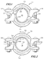
Figure 1 shows acoupling 11 havingcoupling segments connection members 17 and 19, the connection members including threadedfasteners 21. Thesegments ring gasket 23 captured between the segments. When the segments are supported in this manner it is possible to insert pipe elements into thecentral space 25 between the segments without disassembling the coupling. However, there are some drawbacks to this solution to the problem of installing mechanical couplings. Note in particular that there is a limit on the pipe element diameter tolerance variations which can be accepted bycoupling 11. If the pipe elements are sufficiently out of round, or if their ends are flared near the maximum degree permitted by specification, it will be difficult to impossible to insert them into thecentral space 25 between thesegments projections 29 which extend into the central space. Furthermore, the ring gasket itself can resist pipe element insertion when the distortion is not controlled. Many mass produced pipe elements are out of round to some degree and roll grooved pipe elements may be flared to some degree. Use of thecoupling 11 therefore places tighter tolerances on these parameters, limiting the pipe elements which can be effectively used with such couplings and making the pipe elements more expensive as they must either be "selected" pipe elements within a permissible tolerance or the tolerances determining manufacturing acceptance must be tighter. - Thus, there is clearly a need for a pipe coupling which can be used with pipe elements having a generous tolerance range on parameters such as out of roundness and flare, yet will allow pipe elements to be inserted reliably without disassembly of the coupling.
-
US 3 054 629 discloses a pipe coupling, with two identical coupling housings, secured by bolts and extending by bolt pads.
WO2010/002695 discloses a method that includes the steps of placing the assembled coupling over one end of a pipe, aligning the second pipe with the first pipe, sliding the coupling off the end of the first pipe so that a portion of the coupling is around each pipe, and securing the coupling. Summary - The invention concerns a method for coupling first and second pipe elements in end to end relation according to claim 1. The coupling comprises a plurality of segments joined end to end surrounding a central axis and defining a central space for receiving the pipe elements. At least one of the segments comprises a pair of projections positioned in spaced apart relation on opposite sides of the one segment and extending toward the central axis. At least a portion of each of the projections is engageable with a respective one of the pipe elements. Each of the projections has an arcuate surface facing the central axis. A back wall extends between the projections. The back wall has an arcuate surface facing the central axis.
- The coupling comprises at least one of the projections with first and second outwardly facing surface portions. The first surface portion is angularly oriented relatively to the second surface portion. The first surface portion may subtend an angle of about 35° to about 60° measured with respect to the central axis. The first surface portion may be centered on a line extending from the central axis and oriented from an angle of about 30° to about 50° measured from a first line extending between a first end of the one segment and a second end of the one segment. The first surface portion may have an orientation angle relative to the second surface portion from about 15° to about 60°. In this example embodiment the one projection may further comprise a third outwardly facing surface portion. The third surface portion is angularly oriented relatively to the second surface portion. The third surface portion subtends an angle of about 35° to about 60° measured with respect to the central axis. The second surface portion is positioned between the first and third surface portions. The third surface portion may be centered on a line extending from the central axis and oriented from an angle of about 30° to about 50° measured from the first line. The third surface portion may have an orientation angle relative to the second surface portion from about 15° to about 60°.
- At least one notch may be positioned in at least one of the projections, the notch located at an end of the one segment. In an example embodiment, the at least one notch includes first and second notches positioned on opposite ends of the one segment.
- In a particular example, a first and a second of the segments of the coupling are joined end to end surrounding the central axis. In this example, the coupling further comprises a ring gasket positioned between the first and second segments. The ring gasket supports the first and second segments in spaced apart relation sufficient to insert the pipe elements between the segments. The first and second segments have sidewalls from which the projections extend. The back wall and the projections of each said segment cooperate to define a pocket for receiving the ring gasket.
- The coupling for joining pipe elements in end to end relation may also encompass a segment. The coupling comprises a plurality of the segments joined end to end surrounding a central axis and defining a central space for receiving the pipe elements. The segment comprises a pair of projections positioned in spaced apart relation on opposite sides of the segment. The projections extend toward the central axis. At least a portion of each of the projections are engageable with a respective one of the pipe elements. Each of the projections has an arcuate surface facing the central axis. A back wall extends between the projections. The back wall has an arcuate surface facing the central axis.
- At least one of the projections may comprise first and second outwardly facing surface portions. The first surface portion is angularly oriented relatively to the second surface portion. The first surface portion may subtend an angle of about 35° to about 60° measured with respect to the central axis. The first surface portion may be centered on a line extending from the central axis and oriented from an angle of about 30° to about 50° measured from a first line extending between a first end of the one segment and a second end of the one segment. The first surface portion may have an orientation angle relative to the second surface portion from about 15° to about 60°. The projection may further comprise a third outwardly facing surface portion. The third surface portion is angularly oriented relatively to the second surface portion. The third surface portion may subtend an angle of about 35° to about 60° measured with respect to the central axis. The second surface portion is positioned between the first and third surface portions. The third surface portion may be centered on a line extending from the central axis and oriented from an angle of about 30° to about 50° measured from the first line. The third surface portion may have an orientation angle relative to the second surface portion from about 15° to about 60°.
- The segment may further comprise at least one notch positioned in at least one of the projections, the notch located at an end of the segment. The at least one notch may include first and second notches positioned on opposite ends of the one segment.
- The invention relates to a method of coupling first and second pipe elements in end to end relation. In one embodiment, the method includes:
- using a pipe coupling having first and second coupling segments attached to one another end to end surrounding a central axis and defining a central space, the coupling segments being supported in spaced apart relation on an elastic ring gasket, the coupling segments having adjustable connection members at each end for drawing the coupling segments toward the central space when the connection members are tightened, at least one of the coupling segments having:
- a pair of projections positioned in spaced apart relation on opposite sides of the one coupling segment and extending toward the central axis, at least a portion of each of the projections being engageable with a respective one of the pipe elements, each of the projections having an arcuate surface facing the central axis,
- wherein at least one of the projections comprises first and second outwardly facing surface portions, the first surface portion being angularly oriented relatively to the second surface portion, the first surface portion subtending an angle of about 35° to about 60° measured with respect to the central axis;
- inserting the first pipe element into the central space from one side of the pipe coupling, the first pipe element contacting said first surface portion thereby rotating the coupling segments relatively to one another about an axis passing through the connection members to provide clearance for inserting the first pipe element and engaging it with said coupling elements;
- inserting the second pipe element into the central space from an opposite side of the pipe coupling; and
- tightening the connection members and thereby drawing the coupling segments toward one another and into engagement with the first and second pipe elements to couple them in end to end relation.
- The method may further include the step of inserting the second pipe element into the central space from an opposite side of the coupling contacting said first surface portion engaging and thereby rotating the coupling segments relatively to one another about the axis passing through the connection members to provide clearance for inserting the second pipe element and engaging it with said coupling elements.
Further embodiments are claimed independent claims 3 to 15. -
-
Figure 1 is an elevational view of an example mechanical pipe coupling not according to the invention; -
Figure 2 is an elevational view of an example mechanical pipe coupling according to the invention; -
Figure 3 is a cross sectional view of a segment of an example mechanical pipe coupling according to the invention taken at line 3-3 ofFigure 2 ; -
Figures 4A and 4B are isometric views of segments of example mechanical pipe couplings according to the invention; -
Figures 5A and 5B are elevational views of segments of example mechanical pipe couplings according to the invention; and -
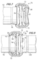
Figures 6-9 are longitudinal sectional views illustrating an example method of forming a pipe joint according to the invention. The longitudinal section view depicted inFigure 6 is taken at line 6-6 ofFigure 5A . The longitudinal section view depicted inFigure 7 is taken at line 7-7 ofFigure 5A . -
Figure 2 shows an example embodiment of acoupling 10 according to the invention.Coupling 10 comprisessegments central axis 16 and defining acentral space 18.Central space 18 receives the pipe elements to be joined in end to end relation, the longitudinal axis of the pipe elements substantially aligning with thecentral axis 16. Each of thesegments connection members lug 24 which projects from the segment and receives a threadedfastener 26.Fasteners 26 are adjustably tightenable so as to draw thesegments central axis 16 to engage the pipe elements and form the joint. - As shown in cross section in
Figure 3 , each segment (segment 12 being shown) has a pair ofprojections central axis 16, and at least a portion of each projection is engageable with a respective pipe element to provide mechanical engagement and hold the pipe elements in end to end relation. Theprojections Figure 3 , each projection has anarcuate surface 32 facingcentral axis 16. - The
segments projections sidewalls back wall 40, and together the sidewalls and back wall define apocket 42. Backwall 40 extends betweenprojections arcuate surface 44 which faces thecentral axis 16.Pocket 42 receives a ring gasket 43 (Figure 3 ) positioned between thesegments 12 and 14 (seeFigure 2 ) to ensure a fluid-tight seal. - As shown in
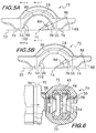
Figures 4A-5B , projections such as 28 and 30 may comprise at least two outwardly facingsurface portions gasket pocket 42. In this example,surface portion 78 is angularly oriented with respect tosurface portion 80. - As shown in
Figures 4A and5A ,surface portion 80 may be angularly oriented relative to the outermost surface of projection 28 (the surface ofprojection 28 farthest away from gasket pocket 42), thereby defining an angled surface or chamfer extending between the outermost surface ofprojection 28 andarcuate surface 32 of projection 28 (SeeFig. 3 ). In this example,surface portion 78 may have arelative orientation angle 82 from about 15° to about 45° and may subtend anangle 84 from about 35° to about 60° as measured with respect to thecentral axis 16. Alternatively, as shown inFigures 4B and5B ,surface portion 80 may correspond to the outermost surface ofprojection 28 such thatsurface portion 80 does not comprise an angled surface or chamfer extending between the outermost surface ofprojection 28 andarcuate surface 32 ofprojection 28. In this example,surface portion 78 may have arelative orientation angle 82 from about 15° to about 60° and may subtend anangle 84 from about 35° to about 60° as measured with respect to thecentral axis 16. -
Surface portion 78 may further be centered on aline 86 extending from thecentral axis 16, as shown inFigures 5A and 5B .Center line 86 ofsurface portion 78 may have anorientation angle 88 measured from theline 55 which extends between the ends 56 and 58 of thesegment 72.Orientation angle 88 may range from about 30° to about 50°. As shown inFigures 5A and 5B ,segment 72 has a third outwardly facingsurface portion 90 which is angularly oriented with respect tosurface portion 80. The ranges for the angular orientation ofsurface portion 90 with respect tosurface portion 80 may be the same as forsurface portion 78, but the actual orientation angle ofsurface portion 90 for a particular coupling need not be the same as the orientation angle ofsurface 78, although for practical designs it is advantageous that all of such surface portions be the same on the segments forming a coupling. - The advantage of angularly oriented
surface portions Figures 6-9 , which illustrate an example method of coupling pipe elements according to the invention. It is advantageous to have acoupling 73 formed of segments such as 12, 13, 14, 15, 66, or 72 which does not have to be disassembled and then reassembled around the pipe elements to form the joint between them. In the example shown inFigures 6-9 , thecoupling 73 is formed ofsegments 72, used by way of example. Couplings such as 10, 11 and 73 are regarded as "installation ready" from the factory because, as shown forcoupling 10 inFigure 2 by way of example, the segments for such couplings are attached to one another with threadedfasteners 26 and supported in spaced apart relation on thering gasket 43 at a sufficient distance to permit pipe elements to be inserted into thecentral space 18 without disassembling the coupling.Figure 6 illustrates insertion of apipe element 92 intocentral space 18 ofcoupling 73. Insertion is initiated by contacting the end of thepipe element 92 with the angularly oriented surfaces 90 onprojections 28 onsegments 72. -
Surfaces 90 facilitate insertion by acting as lead in guides to center thepipe element 92 and also initiate rotation of thesegments 72 about anaxis 94 passing through the connection members. This rotation of the segments is illustrated inFigure 7 . Thering gasket 43, due to its elastic and resilient properties, acts as a spring which allows thesegments 72 to rotate out of the way and admit thepipe element 92 into thecentral space 18. Once thepipe element 92 is sufficiently engaged with thecoupling 10 within thecentral space 18 the elastic biasing of thering gasket 43 restores thecoupling segments projections 28 align withgroove 96 in thepipe element 92, or when the end of the pipe element contacts thegasket stop 98. As shown inFigure 8 , the restoring force provided by the spring action of thering gasket 43 permits anotherpipe element 100 to be inserted from the opposite side ofcoupling 10. Upon insertion into thecentral space 18, thepipe element 100 contacts angularly oriented surfaces 78 on theprojections 30 ofsegments 72 and the segments rotate aboutaxis 94, out of the way of the pipe element to permit insertion. Oncepipe element 100 is sufficiently engaged with thecoupling 73, as shown inFigure 9 , the fasteners joining the segments 72 (see alsoFigure 2 ) are tightened to engage theprojections pipe elements circumferential grooves 96, but other types of pipe elements, such as plain end, shouldered, as well as shoulder and bead pipe elements are also feasible. As shown inFigures 2 and4A-5B , anotch 102 may also be incorporated into theprojections segments second notches 102 can be positioned on opposite ends of thesegments - Use of the angularly oriented
surface portions coupling 10 by the insertion method. End flare occurs when pipe elements are cold worked, by rolling for example, to form a circumferential groove, and the expanded diameter of the flared end might pose some difficulty to insertion but for the angularly oriented surface portions and the ability of the coupling segments to rotate relatively to one another aboutaxis 94. Thenotches 102 also help in allowing flared pipe to be used with the joint assembly method according to the invention. - Use of the angularly oriented
surface portions central axis 16 of thecoupling 10 to be readily received within thecentral space 18. -
Figures 4A-5B illustrate another feature of the coupling according to the invention.Figures 4A and 4B depict arigid coupling segment 66 for use with circumferentially grooved pipe elements.Segment 66 has interfacingsurfaces projections U.S. Patent No. 4,611,839 andU.S. Patent No. 4,639,020 . -
Figures 5A and 5B show asegment 72 of a more flexible coupling. The interfacing surfaces 74 and 76 between thesegments projections - The angularly oriented surfaces described above and claimed herein are applicable to both rigid and flexible couplings. Thus, it is understood that features or elements of the disclosed angularly oriented surfaces that are described or depicted with respect to only one of the segments (66 or 72) or to only one of the projections (28 or 30) are also applicable to, and includable in, the other segment (66 or 72) or the other projection (28 or 30).
- Pipe couplings according to the invention permit non-deforming couplings to be used as installation ready couplings and require less energy to install because there is no significant energy expended to deform the couplings when effecting the pipe joint. This corresponds to lower fatigue when manually forming joints with hand tools as well as fewer battery changes when cordless electric power tools are used.
Claims (15)
- A method for coupling first and second pipe elements in end to end relation, said method comprising:using a pipe coupling (10) having first and second coupling segments (12, 14; 66; 72) attached to one anotherend to end surrounding a central axis (16) and defining a central space (18), said coupling segments (12, 14; 66; 72)being supported in spaced apart relation on an elastic ring gasket (43), said coupling segments (12, 14: 66; 72)having adjustable connection members (20, 22) at each end for drawing said coupling segments (12, 14; 66; 72)toward said central space (18) when said connection members (20, 22) are tightened, at least one of said coupling segments (12, 14; 66; 72) comprising:a pair of projections (28, 30) positioned in spaced apart relation on opposite sides of said one coupling segment (12, 14; 66; 72) and extending toward said central axis (16), at least a portion of each of said projections (28, 30) being engageable with a respective one of said pipe elements (92, 100), each of said projections (28, 30) having an arcuate surface (32) facing said central axis (16),wherein at least a first of said projections (28, 30) comprises first and second outwardly facing surface portions (78, 80), said first surface portion (78) being angularly oriented relatively to said second surface portion (80), said first surface portion (78) subtending an angle (84) of about 35° to about 60° measured with respect to said central axis (16);inserting said first pipe element (92) into said central space (18) from one side of said pipe coupling (10), saidfirst pipe element (92) contacting said first surface portion (78) of said first projection (28) of said one coupling segment (12, 14; 66; 72) thereby rotating said coupling segments (12, 14; 66; 72) relatively to one anotherabout an axis passing through said connection members (20, 22) to provide clearance for inserting said first pipe element (92) and engaging said first pipe element with said coupling segments (12, 14; 66; 72); insertingsaid second pipe element (100) into said central space (18) from an opposite side of said pipe coupling (10); andtightening said connection members (20, 22) and thereby drawing said coupling segments (12, 14; 66; 72) toward one another and into engagement with said first and second pipe elements (92, 100) to couple them in end to end relation.
- The method according to claim 1, wherein a second of said projections (28, 30) of said one coupling segment (12, 14; 66; 72) comprises first and second outwardly facing surface portions (78, 80),
wherein said step of inserting said second pipe element (100) into said central space (18) from an opposite side of said pipe coupling (10) comprises engaging said coupling segments (12,14; 66; 72) with said second pipe element (100) contacting said first surface portion (78) of said second projection (30) of said one coupling segment thereby rotating said coupling segments relatively to one another about said axis passing through said connection members (20, 22) to provide clearance for inserting said second pipe element and engaging said second pipe element with said coupling elements. - The method according to claim 1, wherein said first outwardly surface portion (78) is centered on a line (86) extending from said central axis (16) and oriented from an angle of about 30° to about 50° measured from a first line (55) extending between a first end (56) of said one coupling segment and a second end (58) of said one coupling segment.
- The method according to claim 1, wherein said first outwardly surface portion (78) has an orientation angle relative to said second surface portion (80) from about 15° to about 60°.
- The method according to claim 3, wherein said at least one projection (28) further comprises a third outwardly facing surface portion (90), said third surface portion (90) being angularly oriented relatively to said second surface portion (80), said third surface portion (90) subtending an angle (84) along said projection (28) of about 35° to about 60° measured with respect to said central axis (16), said second surface portion (80) being positioned between said first (78) and third (90) surface portions.
- The method according to claim 5, wherein said third surface portion:is centered on a line (86) extending from said central axis (16) and oriented from an angle of about 30° to about 50° measured from said first line (55), orhas an orientation angle relative to said second surface portion (80) from about 15° to about 60°.
- The method according to claim 1, wherein said first and second segments comprise sidewalls (36, 38) from which said projections (28, 30) extend and a back wall extending between said projections (28, 30), said sidewalls (36, 38) being attached to said back wall, said sidewalls (36, 38) and said back wall together defining a pocket (42), said pocket (42) being adapted to receive said ring gasket (43).
- The method according to claim 1, further comprising at least one notch (102) positioned in at least one of said projections (28, 30) of each said segment, each said notch located at an end of one of said segments; preferably said at least one notch comprises first and second notches (102) positioned on opposite ends of said one segment.
- The method according to claim 1, wherein said step of inserting said first pipe element (92) into said central space (18) does not comprise disassembling the pipe coupling (10).
- The method according to claim 2, wherein said step of inserting said second pipe element (100) into said central space (18) does not comprise disassembling the pipe coupling (10).
- The method according to claim 2, wherein, prior to insertion of said first (92) and second (100) pipe elements into said central space (18), said first and second segments (12, 14; 66; 72) are positioned in their original relative angular positions, and wherein, following insertion of said first and second pipe elements into said central space (18) and tightening of said connection members, said elastic ring gasket (43) is elastically biased to restore said first and second segments (12, 14; 66; 72) toward their original relative angular positions.
- The method according to claim 1, wherein said first and second pipe elements (92, 100) have respective flared ends; preferably
said flared ends of said first and second pipe elements (92, 100) define respective circumferential grooves (96),
and wherein said step of tightening said connection members comprises effecting engagement between said projections of each said coupling segment and a corresponding circumferential groove of said first and second pipe elements. - The method according to claim 1, wherein, prior to insertion of said first and second pipe elements into said central space, said first and second pipe elements are not axially aligned with said central axis of said pipe coupling.
- The method according to claim 1, wherein said pipe coupling is a rigid pipe coupling (66); preferably each of said first and second coupling segments has respective interfacing surfaces (68, 70), wherein said interfacing surfaces of each of said coupling segments have opposite angular orientations with respect to one another, and wherein, when said connection members are tightened, said interfacing surfaces of said first coupling segment contact counterpart interfacing surfaces of said second coupling segment and said first and second coupling segments are forced to rotate about a vertical axis in opposite directions relatively to one another.
- The method according to claim 1, wherein said pipe coupling is a flexible pipe coupling.
Applications Claiming Priority (2)
| Application Number | Priority Date | Filing Date | Title |
|---|---|---|---|
| US13/300,756 US20130125373A1 (en) | 2011-11-21 | 2011-11-21 | Coupling with projections having angularly oriented surface portions |
| PCT/US2012/064474 WO2013078021A1 (en) | 2011-11-21 | 2012-11-09 | Coupling with projections having angularly oriented surface portions |
Publications (3)
| Publication Number | Publication Date |
|---|---|
| EP2783146A1 EP2783146A1 (en) | 2014-10-01 |
| EP2783146A4 EP2783146A4 (en) | 2015-06-10 |
| EP2783146B1 true EP2783146B1 (en) | 2016-09-07 |
Family
ID=48425410
Family Applications (1)
| Application Number | Title | Priority Date | Filing Date |
|---|---|---|---|
| EP12851307.4A Active EP2783146B1 (en) | 2011-11-21 | 2012-11-09 | Coupling with projections having angularly oriented surface portions |
Country Status (16)
| Country | Link |
|---|---|
| US (2) | US20130125373A1 (en) |
| EP (1) | EP2783146B1 (en) |
| JP (1) | JP6132846B2 (en) |
| KR (1) | KR101989887B1 (en) |
| CN (1) | CN104204642B (en) |
| AU (1) | AU2012340939B2 (en) |
| BR (1) | BR112014012188B1 (en) |
| CA (1) | CA2856371C (en) |
| ES (1) | ES2604960T3 (en) |
| HK (1) | HK1202609A1 (en) |
| IL (1) | IL232614A (en) |
| IN (1) | IN2014CN04543A (en) |
| MX (1) | MX345784B (en) |
| SG (1) | SG11201402498QA (en) |
| TW (1) | TWI588395B (en) |
| WO (1) | WO2013078021A1 (en) |
Cited By (1)
| Publication number | Priority date | Publication date | Assignee | Title |
|---|---|---|---|---|
| US11971120B2 (en) | 2021-02-09 | 2024-04-30 | ASC Engineered Solutions, LLC | Pre-assembled coupling assemblies with pipe fitting |
Families Citing this family (23)
| Publication number | Priority date | Publication date | Assignee | Title |
|---|---|---|---|---|
| US7086131B2 (en) * | 2004-05-14 | 2006-08-08 | Victaulic Company | Deformable mechanical pipe coupling |
| KR101811708B1 (en) * | 2009-10-27 | 2017-12-22 | 타이코 파이어 프로덕츠 엘피 | Systems and methods for pipe couplings |
| GB2516452A (en) * | 2013-07-22 | 2015-01-28 | Jcco 331 Ltd | Improvements in and relating to pipe coupling |
| JP3201323U (en) * | 2015-09-18 | 2015-12-03 | 株式会社永島製作所 | Pipe fitting |
| MX2022004279A (en) | 2015-09-18 | 2023-08-03 | Victaulic Co Of America | Valve and coupling. |
| USD833265S1 (en) * | 2015-10-22 | 2018-11-13 | Bioflex Solutions, Llc | Hygienic clamp |
| US9903515B2 (en) * | 2015-12-09 | 2018-02-27 | Victaulic Company | Seal with lip projections |
| WO2017116969A1 (en) * | 2015-12-28 | 2017-07-06 | Victaulic Company | Adapter coupling |
| MX2018009094A (en) * | 2016-01-26 | 2018-11-09 | Victaulic Co Of America | Pipe element having wedging groove. |
| US10110757B2 (en) * | 2016-02-16 | 2018-10-23 | Canon Kabushiki Kaisha | Printing apparatus and notification method of printing apparatus abnormality in a printing apparatus |
| US10859190B2 (en) * | 2016-05-16 | 2020-12-08 | Victaulic Company | Sprung coupling |
| KR102223297B1 (en) * | 2017-02-02 | 2021-03-05 | 빅톨릭 컴패니 | Mechanical couplings for mechanical and structural pipes |
| WO2018222604A1 (en) * | 2017-05-30 | 2018-12-06 | Tyco Fire Products Lp | Pre-assembled pipe coupling with an insertion boundary for axial receipt of pipe ends |
| KR101968589B1 (en) * | 2017-05-31 | 2019-08-13 | 강한표 | Grooved coupler |
| US11215301B2 (en) | 2017-07-28 | 2022-01-04 | ASC Engineered Solutions, LLC | Pre-assembled coupling assembly with flexible hose adapter |
| US11268638B2 (en) | 2017-07-28 | 2022-03-08 | ASC Engineered Solutions, LLC | Pre-assembled coupling assemblies with pipe fitting |
| JP2019132425A (en) * | 2018-01-29 | 2019-08-08 | 日本ヴィクトリック株式会社 | Pipe joint structure |
| KR102033757B1 (en) * | 2018-12-13 | 2019-10-17 | 주식회사 뉴아세아조인트 | Coupling assembly for connecting pipes and manufacturing method of the same |
| CN209540252U (en) * | 2019-01-05 | 2019-10-25 | 潍坊和特管业发展有限公司 | Quick-installment hoop |
| KR102094381B1 (en) * | 2019-07-18 | 2020-03-27 | 주식회사 뉴아세아조인트 | Coupling assembly for connecting pipes and manufacturing method of the same |
| US11781683B2 (en) | 2019-11-15 | 2023-10-10 | Victaulic Company | Shrouded coupling |
| EP4241007A1 (en) | 2020-11-06 | 2023-09-13 | Victaulic Company | Coupling having rotation limited segments |
| CN112648456B (en) * | 2020-12-14 | 2022-07-05 | 天津爱尔普科技发展有限公司 | Welded type air heater water inlet and outlet pipe joint |
Family Cites Families (96)
| Publication number | Priority date | Publication date | Assignee | Title |
|---|---|---|---|---|
| US3291506A (en) | 1966-12-13 | Pipe joints and the oasketing thereof | ||
| US1331986A (en) | 1919-08-04 | 1920-02-24 | American Steam Conveyor Corp | Ash-conveyer |
| US2028182A (en) | 1932-04-28 | 1936-01-21 | Jr Ferd Barnickol | Coupling |
| US1994361A (en) | 1933-01-21 | 1935-03-12 | Champion Machine & Forging Com | Gasket for pipe joints |
| US2230287A (en) | 1939-07-11 | 1941-02-04 | Dresser Mfg Company | Split repair sleeve for pipe lines |
| US2428189A (en) | 1945-01-08 | 1947-09-30 | Parker Appliance Co | Coupling for hose |
| US2486120A (en) | 1945-08-31 | 1949-10-25 | Johns Manville | Pipe coupling assembly |
| US2473046A (en) | 1945-11-29 | 1949-06-14 | Jr Charles Adams | Pipe clamp |
| US2464416A (en) | 1946-04-20 | 1949-03-15 | Weatherhead Co | Hose end assembly |
| US2473102A (en) | 1947-02-06 | 1949-06-14 | Victaulic Co Of America | Coupling for brittle pipes |
| US2821415A (en) | 1953-04-09 | 1958-01-28 | Race & Race Inc | Grooved and internally reinforced pipe end |
| US3015502A (en) | 1957-11-29 | 1962-01-02 | Victaulic Co Of America | Grooved tubing for connection with sleeve type coupling |
| US3024046A (en) | 1958-05-29 | 1962-03-06 | Victaulic Co Of America | Couplings with pipe gripping means for plain end pipe |
| US3006663A (en) | 1958-08-11 | 1961-10-31 | Lee Clay Products Company | Pipe clamp with resilient member |
| US3054629A (en) * | 1958-09-04 | 1962-09-18 | Victaulic Co Of America | Pipe couplings |
| US3086797A (en) | 1958-11-13 | 1963-04-23 | Ernest C Webb | Coupling device |
| US3201149A (en) | 1961-12-01 | 1965-08-17 | Parker Hannifin Corp | Tube coupling |
| US3351352A (en) | 1962-02-27 | 1967-11-07 | Victaulic Co Of America | Gasket for pipe joint |
| GB1038515A (en) | 1963-07-31 | 1966-08-10 | British Aluminium Co Ltd | Improvements in or relating to multi-purpose tools |
| US3403931A (en) | 1964-08-11 | 1968-10-01 | Gray Tool Co | Clamp |
| US3365730A (en) | 1964-12-30 | 1968-01-30 | Peter P. Chiappetta | Water saver flush valve |
| US3251615A (en) * | 1965-02-19 | 1966-05-17 | Nat Tank Co | Grooved pipe coupling |
| US3362730A (en) | 1965-06-07 | 1968-01-09 | Victaulic Co Of America | Side outlet coupling |
| US3695638A (en) | 1970-03-18 | 1972-10-03 | Victaulic Co Of America | Coupling for plastic pipe |
| BE789346A (en) | 1971-10-01 | 1973-01-15 | Victaulic Co Of America | PIPE ASSEMBLY SYSTEM BY MEANS OF STUDS AND FITTINGS FOR THEM |
| DE2244862B1 (en) | 1972-09-13 | 1973-12-06 | Jean Walterscheid Gmbh, 5204 Lohmar | SCREW CONNECTION |
| US4311248A (en) | 1974-11-04 | 1982-01-19 | Construction Forms, Inc. | High pressure coupling apparatus |
| US3977705A (en) * | 1975-08-20 | 1976-08-31 | Aeroquip Corporation | Reducing type coupling |
| US4114414A (en) | 1977-04-29 | 1978-09-19 | E.G. Sprinkler Corporation | Backup roll for thin walled pipe grooving device |
| US4163571A (en) | 1977-07-18 | 1979-08-07 | Durapipe Limited | Pipe couplings |
| US4432558A (en) | 1978-01-03 | 1984-02-21 | Westerlund Robert E | Concrete pumping swivel coupling apparatus with seal |
| US4289335A (en) | 1980-01-11 | 1981-09-15 | Wilkerson Corporation | Modular clamping system for pressure fluid components |
| EP0034436B1 (en) | 1980-02-18 | 1983-05-25 | Hunting Oilfield Services (Uk) Limited | Pipe connector |
| US4391458A (en) | 1981-04-10 | 1983-07-05 | Blakeley Engineering Limited | Pipe coupling with gasket locating means |
| US4408788A (en) * | 1981-09-23 | 1983-10-11 | Grinnell Fire Protection Systems Company, Inc. | Hingeable split pipe collar |
| US4601495A (en) | 1982-04-23 | 1986-07-22 | Victaulic Company Of America | Pipeline system and method of assembly |
| US4522433A (en) | 1982-05-14 | 1985-06-11 | Stanley Aviation Corporation | Spherical seat flexible O-ring coupling |
| US4611839A (en) * | 1983-07-12 | 1986-09-16 | Victaulic Company Of America | Self-adjusting pipe clamp and coupling |
| US4639020A (en) | 1983-07-12 | 1987-01-27 | Victaulic Company Of America | Self-adjusting pipe clamp and coupling |
| US4702500A (en) | 1985-12-20 | 1987-10-27 | Victaulic Company Of America | Fire resistant seal |
| US4643461A (en) | 1985-12-20 | 1987-02-17 | Victaulic Company Of America | Fire resistant seal |
| US5058931A (en) | 1988-11-28 | 1991-10-22 | Gustin-Bacon Division, A Division Of Tyler Pipe | Clamp with teeth for grooved pipes |
| US4915418A (en) * | 1989-05-19 | 1990-04-10 | Urdan Industries (Usa), Inc. | Hinged pipe coupling |
| US5149143A (en) | 1989-07-20 | 1992-09-22 | National-Oilwell | Connector assembly with detachable sleeve |
| US5080400A (en) | 1990-04-30 | 1992-01-14 | Abb Vetro Gray Inc. | Double lobe tubular connector clamp |
| US5018768A (en) | 1990-07-19 | 1991-05-28 | Quikcoup, Incorporated | Pipe coupling hinge |
| JPH04339527A (en) | 1991-05-16 | 1992-11-26 | Mirano:Kk | Device for forming tip part of pipe |
| US5190324A (en) | 1991-11-06 | 1993-03-02 | M&Fc Holding Company, Inc. | Pipe restraining member |
| US5246256A (en) | 1991-12-19 | 1993-09-21 | Victaulic Company Of America | Roll grooved pipe |
| GB2263323B (en) * | 1992-01-17 | 1995-04-05 | Graham Thomas Wallbank | Pipe coupling |
| US5249829A (en) | 1992-07-06 | 1993-10-05 | Quikcoup, Inc. | Pipe coupling gasket insert |
| US5443581A (en) | 1992-12-03 | 1995-08-22 | Wood George & Co., Inc. | Clamp assembly for clamp hub connectors and a method of installing the same |
| US5282654A (en) | 1993-04-26 | 1994-02-01 | Quikcoup, Inc. | Pipe coupling sleeve |
| US5450738A (en) | 1993-08-31 | 1995-09-19 | Grinnell Corporation | Method and apparatus for forming piping element connections having multiple outward steps |
| EP0646747A1 (en) | 1993-09-17 | 1995-04-05 | Ck Metals, Ltd. | Pipe connecting structure |
| US5603508A (en) | 1996-05-20 | 1997-02-18 | Victaulic Company Of America | Gasket for lateral outlet segmented pipe coupling |
| AU3660297A (en) | 1996-06-18 | 1998-01-07 | Victaulic Company Of America | Pipe coupling for plain ended pipe |
| US5778715A (en) | 1996-11-05 | 1998-07-14 | Grinnell Corporation | Cold rolling positioning roller assembly |
| DE19705712A1 (en) | 1997-02-14 | 1998-08-20 | Bodenseewerk Geraetetech | Tension ring for connecting cylindrical assemblies of missiles |
| US6076861A (en) * | 1997-12-25 | 2000-06-20 | The Victaulic Co., Of Japan, Ltd. | Housing type pipe coupling |
| US6227577B1 (en) | 1997-12-25 | 2001-05-08 | Victaulic Co., Of Japan, Ltd. | Housing type pipe coupling |
| US6105972A (en) * | 1998-01-12 | 2000-08-22 | S & B Technical Products, Inc. | Pipe gasket with improved low insertion geometry |
| US5951066A (en) | 1998-02-23 | 1999-09-14 | Erc Industries, Inc. | Connecting system for wellhead components |
| EP0959286A3 (en) | 1998-05-20 | 2003-01-22 | Rasmussen GmbH | Pipe coupling |
| US6139069A (en) * | 1998-08-24 | 2000-10-31 | Central Sprinkler Corporation | Universal mechanical coupling with interfitting ends |
| JP3032200B1 (en) | 1999-03-23 | 2000-04-10 | バンテック株式会社 | Pipe joint structure |
| US6375228B1 (en) | 1999-03-25 | 2002-04-23 | Construction Forms, Inc. | Coupling units connecting tubular members having a hardened inner wall for carrying mechanically abrasive fluid concrete |
| US6626466B1 (en) * | 1999-08-05 | 2003-09-30 | Victaulic Company Of America | Anti-mismatch or near-sized coupling segments |
| US20010054820A1 (en) | 2000-06-19 | 2001-12-27 | Starita Joseph M. | Corrugated plastic pipe sections having flanged ends and structurally tight joints thereof |
| US6502865B1 (en) | 2000-08-09 | 2003-01-07 | Dynamic Air | Pipe coupler and method of coupling |
| US6393885B1 (en) | 2000-11-07 | 2002-05-28 | Hegenscheidt Mfd Corporation | Tooling for deep rolling fillets of crankshaft journals |
| US6565129B2 (en) | 2001-06-21 | 2003-05-20 | Halliburton Energy Services, Inc. | Quick connect system and method for fluid devices |
| US20030062718A1 (en) * | 2001-09-28 | 2003-04-03 | Central Sprinkler Corporation | Ferrous pipe couplings and prelubricated coupling gaskets |
| EP1583965A1 (en) | 2003-01-08 | 2005-10-12 | Pharmacia & Upjohn Company LLC | Method for determining molecular affinities for human serum albumin |
| US7144047B2 (en) | 2003-12-10 | 2006-12-05 | Victaulic Company | Flexible pipe coupling |
| US6840782B1 (en) | 2004-02-26 | 2005-01-11 | Aaron M. Borden | Dual-sectioned grounding bushing assembly |
| US8267432B2 (en) * | 2004-03-26 | 2012-09-18 | Victaulic Company | Coupling having angularly oriented key surfaces |
| JP2007530886A (en) | 2004-03-26 | 2007-11-01 | ヴィクトリック カンパニー | Pipe coupling with wedge-shaped key |
| US7086131B2 (en) | 2004-05-14 | 2006-08-08 | Victaulic Company | Deformable mechanical pipe coupling |
| US7712796B2 (en) | 2004-05-14 | 2010-05-11 | Victaulic Company | Deformable mechanical pipe coupling |
| EP2113701B1 (en) * | 2005-10-26 | 2010-10-06 | Victaulic Company | Coupling having angularly oriented cavity |
| JP4774325B2 (en) | 2006-04-11 | 2011-09-14 | Jfe継手株式会社 | Housing type pipe fitting |
| US7726703B2 (en) | 2006-06-07 | 2010-06-01 | Victaulic Company | Deformable pipe coupling having multiple radii of curvature |
| JP5030494B2 (en) * | 2006-07-12 | 2012-09-19 | 日本ヴィクトリック株式会社 | Housing type pipe fitting |
| US7950701B2 (en) | 2007-05-15 | 2011-05-31 | Victaulic Company | Pipe coupling having movable gripping bodies |
| WO2009102698A1 (en) | 2008-02-12 | 2009-08-20 | Victaulic Company | Couplings having stiffening ribs and keys with oppositely disposed camming surfaces |
| US20090243289A1 (en) * | 2008-02-12 | 2009-10-01 | Victaulic Company | Couplings Having Stiffening Ribs and Keys with Oppositely Disposed Camming Surfaces |
| US8282136B2 (en) * | 2008-06-30 | 2012-10-09 | Mueller International, Llc | Slip on groove coupling with multiple sealing gasket |
| US8136847B2 (en) | 2009-05-14 | 2012-03-20 | Victaulic Company | Coupling having angularly oriented shoulder surfaces |
| US8038176B2 (en) * | 2009-08-11 | 2011-10-18 | Victaulic Company | Seal with rigid stop ring |
| CA2771891C (en) * | 2009-08-28 | 2017-01-31 | Norma U.S. Holding Llc | Pipe clamp with sleeve and gasket |
| US9482374B2 (en) | 2009-09-17 | 2016-11-01 | Victaulic Company | Seal having projections and coupling having pockets |
| USD665056S1 (en) * | 2011-10-07 | 2012-08-07 | Victaulic Company | Pipe coupling segment |
| USD665057S1 (en) * | 2011-10-07 | 2012-08-07 | Victaulic Company | Pipe coupling segment |
| USD665889S1 (en) * | 2011-10-11 | 2012-08-21 | Victaulic Company | Pipe coupling segment |
| USD665058S1 (en) * | 2011-10-11 | 2012-08-07 | Victaulic Company | Pipe coupling segment |
-
2011
- 2011-11-21 US US13/300,756 patent/US20130125373A1/en not_active Abandoned
-
2012
- 2012-11-09 SG SG11201402498QA patent/SG11201402498QA/en unknown
- 2012-11-09 WO PCT/US2012/064474 patent/WO2013078021A1/en active Application Filing
- 2012-11-09 ES ES12851307.4T patent/ES2604960T3/en active Active
- 2012-11-09 CA CA2856371A patent/CA2856371C/en active Active
- 2012-11-09 AU AU2012340939A patent/AU2012340939B2/en active Active
- 2012-11-09 EP EP12851307.4A patent/EP2783146B1/en active Active
- 2012-11-09 KR KR1020147015491A patent/KR101989887B1/en active IP Right Grant
- 2012-11-09 JP JP2014542360A patent/JP6132846B2/en active Active
- 2012-11-09 CN CN201280067457.3A patent/CN104204642B/en active Active
- 2012-11-09 MX MX2014006096A patent/MX345784B/en active IP Right Grant
- 2012-11-09 BR BR112014012188A patent/BR112014012188B1/en active IP Right Grant
- 2012-11-20 TW TW101143328A patent/TWI588395B/en active
-
2014
- 2014-05-14 IL IL232614A patent/IL232614A/en active IP Right Grant
- 2014-06-18 IN IN4543CHN2014 patent/IN2014CN04543A/en unknown
- 2014-10-30 US US14/528,706 patent/US9528642B2/en active Active
-
2015
- 2015-03-20 HK HK15102848.3A patent/HK1202609A1/en unknown
Non-Patent Citations (1)
| Title |
|---|
| None * |
Cited By (1)
| Publication number | Priority date | Publication date | Assignee | Title |
|---|---|---|---|---|
| US11971120B2 (en) | 2021-02-09 | 2024-04-30 | ASC Engineered Solutions, LLC | Pre-assembled coupling assemblies with pipe fitting |
Also Published As
| Publication number | Publication date |
|---|---|
| JP6132846B2 (en) | 2017-05-24 |
| ES2604960T3 (en) | 2017-03-10 |
| BR112014012188A2 (en) | 2017-05-30 |
| BR112014012188B1 (en) | 2020-04-07 |
| AU2012340939B2 (en) | 2017-09-07 |
| TW201341698A (en) | 2013-10-16 |
| TWI588395B (en) | 2017-06-21 |
| IN2014CN04543A (en) | 2015-09-18 |
| CN104204642B (en) | 2016-10-19 |
| KR101989887B1 (en) | 2019-06-17 |
| IL232614A (en) | 2017-08-31 |
| SG11201402498QA (en) | 2014-09-26 |
| AU2012340939A1 (en) | 2014-06-05 |
| US9528642B2 (en) | 2016-12-27 |
| WO2013078021A1 (en) | 2013-05-30 |
| KR20140103268A (en) | 2014-08-26 |
| HK1202609A1 (en) | 2015-10-02 |
| JP2015501909A (en) | 2015-01-19 |
| US20130125373A1 (en) | 2013-05-23 |
| MX345784B (en) | 2017-02-14 |
| US20150052733A1 (en) | 2015-02-26 |
| IL232614A0 (en) | 2014-06-30 |
| CA2856371C (en) | 2018-05-01 |
| CA2856371A1 (en) | 2013-05-30 |
| MX2014006096A (en) | 2014-10-17 |
| EP2783146A4 (en) | 2015-06-10 |
| CN104204642A (en) | 2014-12-10 |
| EP2783146A1 (en) | 2014-10-01 |
Similar Documents
| Publication | Publication Date | Title |
|---|---|---|
| EP2783146B1 (en) | Coupling with projections having angularly oriented surface portions | |
| AU2018204438B2 (en) | Coupling having gasket pocket of varying depth | |
| AU2017201945B2 (en) | Coupling having gasket pocket of varying depth | |
| EP2284423B1 (en) | Seal with rigid stop ring | |
| WO2013119292A1 (en) | Fitting having receptacle of varying depth |
Legal Events
| Date | Code | Title | Description |
|---|---|---|---|
| PUAI | Public reference made under article 153(3) epc to a published international application that has entered the european phase |
Free format text: ORIGINAL CODE: 0009012 |
|
| 17P | Request for examination filed |
Effective date: 20140617 |
|
| AK | Designated contracting states |
Kind code of ref document: A1 Designated state(s): AL AT BE BG CH CY CZ DE DK EE ES FI FR GB GR HR HU IE IS IT LI LT LU LV MC MK MT NL NO PL PT RO RS SE SI SK SM TR |
|
| DAX | Request for extension of the european patent (deleted) | ||
| REG | Reference to a national code |
Ref country code: DE Ref legal event code: R079 Ref document number: 602012022629 Country of ref document: DE Free format text: PREVIOUS MAIN CLASS: F16L0023180000 Ipc: F16L0017040000 |
|
| RA4 | Supplementary search report drawn up and despatched (corrected) |
Effective date: 20150512 |
|
| RIC1 | Information provided on ipc code assigned before grant |
Ipc: F16L 17/04 20060101AFI20150506BHEP |
|
| REG | Reference to a national code |
Ref country code: HK Ref legal event code: DE Ref document number: 1202609 Country of ref document: HK |
|
| GRAP | Despatch of communication of intention to grant a patent |
Free format text: ORIGINAL CODE: EPIDOSNIGR1 |
|
| INTG | Intention to grant announced |
Effective date: 20160125 |
|
| GRAR | Information related to intention to grant a patent recorded |
Free format text: ORIGINAL CODE: EPIDOSNIGR71 |
|
| GRAS | Grant fee paid |
Free format text: ORIGINAL CODE: EPIDOSNIGR3 |
|
| INTG | Intention to grant announced |
Effective date: 20160623 |
|
| GRAA | (expected) grant |
Free format text: ORIGINAL CODE: 0009210 |
|
| AK | Designated contracting states |
Kind code of ref document: B1 Designated state(s): AL AT BE BG CH CY CZ DE DK EE ES FI FR GB GR HR HU IE IS IT LI LT LU LV MC MK MT NL NO PL PT RO RS SE SI SK SM TR |
|
| REG | Reference to a national code |
Ref country code: GB Ref legal event code: FG4D |
|
| REG | Reference to a national code |
Ref country code: CH Ref legal event code: EP |
|
| REG | Reference to a national code |
Ref country code: IE Ref legal event code: FG4D |
|
| REG | Reference to a national code |
Ref country code: AT Ref legal event code: REF Ref document number: 827198 Country of ref document: AT Kind code of ref document: T Effective date: 20161015 |
|
| REG | Reference to a national code |
Ref country code: DE Ref legal event code: R096 Ref document number: 602012022629 Country of ref document: DE |
|
| REG | Reference to a national code |
Ref country code: FR Ref legal event code: PLFP Year of fee payment: 5 |
|
| REG | Reference to a national code |
Ref country code: LT Ref legal event code: MG4D |
|
| REG | Reference to a national code |
Ref country code: NL Ref legal event code: MP Effective date: 20160907 |
|
| REG | Reference to a national code |
Ref country code: NO Ref legal event code: T2 Effective date: 20160907 |
|
| PG25 | Lapsed in a contracting state [announced via postgrant information from national office to epo] |
Ref country code: HR Free format text: LAPSE BECAUSE OF FAILURE TO SUBMIT A TRANSLATION OF THE DESCRIPTION OR TO PAY THE FEE WITHIN THE PRESCRIBED TIME-LIMIT Effective date: 20160907 Ref country code: RS Free format text: LAPSE BECAUSE OF FAILURE TO SUBMIT A TRANSLATION OF THE DESCRIPTION OR TO PAY THE FEE WITHIN THE PRESCRIBED TIME-LIMIT Effective date: 20160907 Ref country code: LT Free format text: LAPSE BECAUSE OF FAILURE TO SUBMIT A TRANSLATION OF THE DESCRIPTION OR TO PAY THE FEE WITHIN THE PRESCRIBED TIME-LIMIT Effective date: 20160907 Ref country code: FI Free format text: LAPSE BECAUSE OF FAILURE TO SUBMIT A TRANSLATION OF THE DESCRIPTION OR TO PAY THE FEE WITHIN THE PRESCRIBED TIME-LIMIT Effective date: 20160907 |
|
| REG | Reference to a national code |
Ref country code: AT Ref legal event code: MK05 Ref document number: 827198 Country of ref document: AT Kind code of ref document: T Effective date: 20160907 |
|
| PG25 | Lapsed in a contracting state [announced via postgrant information from national office to epo] |
Ref country code: SE Free format text: LAPSE BECAUSE OF FAILURE TO SUBMIT A TRANSLATION OF THE DESCRIPTION OR TO PAY THE FEE WITHIN THE PRESCRIBED TIME-LIMIT Effective date: 20160907 Ref country code: LV Free format text: LAPSE BECAUSE OF FAILURE TO SUBMIT A TRANSLATION OF THE DESCRIPTION OR TO PAY THE FEE WITHIN THE PRESCRIBED TIME-LIMIT Effective date: 20160907 Ref country code: GR Free format text: LAPSE BECAUSE OF FAILURE TO SUBMIT A TRANSLATION OF THE DESCRIPTION OR TO PAY THE FEE WITHIN THE PRESCRIBED TIME-LIMIT Effective date: 20161208 Ref country code: NL Free format text: LAPSE BECAUSE OF FAILURE TO SUBMIT A TRANSLATION OF THE DESCRIPTION OR TO PAY THE FEE WITHIN THE PRESCRIBED TIME-LIMIT Effective date: 20160907 |
|
| REG | Reference to a national code |
Ref country code: ES Ref legal event code: FG2A Ref document number: 2604960 Country of ref document: ES Kind code of ref document: T3 Effective date: 20170310 |
|
| PG25 | Lapsed in a contracting state [announced via postgrant information from national office to epo] |
Ref country code: EE Free format text: LAPSE BECAUSE OF FAILURE TO SUBMIT A TRANSLATION OF THE DESCRIPTION OR TO PAY THE FEE WITHIN THE PRESCRIBED TIME-LIMIT Effective date: 20160907 Ref country code: RO Free format text: LAPSE BECAUSE OF FAILURE TO SUBMIT A TRANSLATION OF THE DESCRIPTION OR TO PAY THE FEE WITHIN THE PRESCRIBED TIME-LIMIT Effective date: 20160907 |
|
| PG25 | Lapsed in a contracting state [announced via postgrant information from national office to epo] |
Ref country code: PL Free format text: LAPSE BECAUSE OF FAILURE TO SUBMIT A TRANSLATION OF THE DESCRIPTION OR TO PAY THE FEE WITHIN THE PRESCRIBED TIME-LIMIT Effective date: 20160907 Ref country code: IS Free format text: LAPSE BECAUSE OF FAILURE TO SUBMIT A TRANSLATION OF THE DESCRIPTION OR TO PAY THE FEE WITHIN THE PRESCRIBED TIME-LIMIT Effective date: 20170107 Ref country code: CZ Free format text: LAPSE BECAUSE OF FAILURE TO SUBMIT A TRANSLATION OF THE DESCRIPTION OR TO PAY THE FEE WITHIN THE PRESCRIBED TIME-LIMIT Effective date: 20160907 Ref country code: AT Free format text: LAPSE BECAUSE OF FAILURE TO SUBMIT A TRANSLATION OF THE DESCRIPTION OR TO PAY THE FEE WITHIN THE PRESCRIBED TIME-LIMIT Effective date: 20160907 Ref country code: BG Free format text: LAPSE BECAUSE OF FAILURE TO SUBMIT A TRANSLATION OF THE DESCRIPTION OR TO PAY THE FEE WITHIN THE PRESCRIBED TIME-LIMIT Effective date: 20161207 Ref country code: SK Free format text: LAPSE BECAUSE OF FAILURE TO SUBMIT A TRANSLATION OF THE DESCRIPTION OR TO PAY THE FEE WITHIN THE PRESCRIBED TIME-LIMIT Effective date: 20160907 Ref country code: PT Free format text: LAPSE BECAUSE OF FAILURE TO SUBMIT A TRANSLATION OF THE DESCRIPTION OR TO PAY THE FEE WITHIN THE PRESCRIBED TIME-LIMIT Effective date: 20170109 Ref country code: SM Free format text: LAPSE BECAUSE OF FAILURE TO SUBMIT A TRANSLATION OF THE DESCRIPTION OR TO PAY THE FEE WITHIN THE PRESCRIBED TIME-LIMIT Effective date: 20160907 |
|
| REG | Reference to a national code |
Ref country code: DE Ref legal event code: R097 Ref document number: 602012022629 Country of ref document: DE |
|
| REG | Reference to a national code |
Ref country code: HK Ref legal event code: GR Ref document number: 1202609 Country of ref document: HK |
|
| REG | Reference to a national code |
Ref country code: CH Ref legal event code: PL |
|
| PLBE | No opposition filed within time limit |
Free format text: ORIGINAL CODE: 0009261 |
|
| STAA | Information on the status of an ep patent application or granted ep patent |
Free format text: STATUS: NO OPPOSITION FILED WITHIN TIME LIMIT |
|
| PG25 | Lapsed in a contracting state [announced via postgrant information from national office to epo] |
Ref country code: DK Free format text: LAPSE BECAUSE OF FAILURE TO SUBMIT A TRANSLATION OF THE DESCRIPTION OR TO PAY THE FEE WITHIN THE PRESCRIBED TIME-LIMIT Effective date: 20160907 Ref country code: LI Free format text: LAPSE BECAUSE OF NON-PAYMENT OF DUE FEES Effective date: 20161130 Ref country code: CH Free format text: LAPSE BECAUSE OF NON-PAYMENT OF DUE FEES Effective date: 20161130 |
|
| 26N | No opposition filed |
Effective date: 20170608 |
|
| REG | Reference to a national code |
Ref country code: IE Ref legal event code: MM4A |
|
| PG25 | Lapsed in a contracting state [announced via postgrant information from national office to epo] |
Ref country code: SI Free format text: LAPSE BECAUSE OF FAILURE TO SUBMIT A TRANSLATION OF THE DESCRIPTION OR TO PAY THE FEE WITHIN THE PRESCRIBED TIME-LIMIT Effective date: 20160907 |
|
| PG25 | Lapsed in a contracting state [announced via postgrant information from national office to epo] |
Ref country code: LU Free format text: LAPSE BECAUSE OF NON-PAYMENT OF DUE FEES Effective date: 20161130 |
|
| REG | Reference to a national code |
Ref country code: FR Ref legal event code: PLFP Year of fee payment: 6 |
|
| PG25 | Lapsed in a contracting state [announced via postgrant information from national office to epo] |
Ref country code: IE Free format text: LAPSE BECAUSE OF NON-PAYMENT OF DUE FEES Effective date: 20161109 |
|
| PG25 | Lapsed in a contracting state [announced via postgrant information from national office to epo] |
Ref country code: HU Free format text: LAPSE BECAUSE OF FAILURE TO SUBMIT A TRANSLATION OF THE DESCRIPTION OR TO PAY THE FEE WITHIN THE PRESCRIBED TIME-LIMIT; INVALID AB INITIO Effective date: 20121109 |
|
| PG25 | Lapsed in a contracting state [announced via postgrant information from national office to epo] |
Ref country code: CY Free format text: LAPSE BECAUSE OF FAILURE TO SUBMIT A TRANSLATION OF THE DESCRIPTION OR TO PAY THE FEE WITHIN THE PRESCRIBED TIME-LIMIT Effective date: 20160907 Ref country code: MC Free format text: LAPSE BECAUSE OF FAILURE TO SUBMIT A TRANSLATION OF THE DESCRIPTION OR TO PAY THE FEE WITHIN THE PRESCRIBED TIME-LIMIT Effective date: 20160907 Ref country code: MK Free format text: LAPSE BECAUSE OF FAILURE TO SUBMIT A TRANSLATION OF THE DESCRIPTION OR TO PAY THE FEE WITHIN THE PRESCRIBED TIME-LIMIT Effective date: 20160907 |
|
| PG25 | Lapsed in a contracting state [announced via postgrant information from national office to epo] |
Ref country code: MT Free format text: LAPSE BECAUSE OF NON-PAYMENT OF DUE FEES Effective date: 20161109 |
|
| REG | Reference to a national code |
Ref country code: FR Ref legal event code: PLFP Year of fee payment: 7 |
|
| PG25 | Lapsed in a contracting state [announced via postgrant information from national office to epo] |
Ref country code: AL Free format text: LAPSE BECAUSE OF FAILURE TO SUBMIT A TRANSLATION OF THE DESCRIPTION OR TO PAY THE FEE WITHIN THE PRESCRIBED TIME-LIMIT Effective date: 20160907 |
|
| REG | Reference to a national code |
Ref country code: DE Ref legal event code: R082 Ref document number: 602012022629 Country of ref document: DE Representative=s name: MEISSNER BOLTE PATENTANWAELTE RECHTSANWAELTE P, DE |
|
| PGFP | Annual fee paid to national office [announced via postgrant information from national office to epo] |
Ref country code: BE Payment date: 20221014 Year of fee payment: 11 |
|
| PGFP | Annual fee paid to national office [announced via postgrant information from national office to epo] |
Ref country code: GB Payment date: 20231013 Year of fee payment: 12 |
|
| PGFP | Annual fee paid to national office [announced via postgrant information from national office to epo] |
Ref country code: ES Payment date: 20231208 Year of fee payment: 12 |
|
| PGFP | Annual fee paid to national office [announced via postgrant information from national office to epo] |
Ref country code: TR Payment date: 20231108 Year of fee payment: 12 Ref country code: NO Payment date: 20231026 Year of fee payment: 12 Ref country code: IT Payment date: 20231113 Year of fee payment: 12 Ref country code: FR Payment date: 20231010 Year of fee payment: 12 Ref country code: DE Payment date: 20231010 Year of fee payment: 12 |
|
| PGFP | Annual fee paid to national office [announced via postgrant information from national office to epo] |
Ref country code: BE Payment date: 20231011 Year of fee payment: 12 |