EP2783100B1 - Compressed air starting system with a liquid detection device for an internal combustion engine, and methods thereof - Google Patents
Compressed air starting system with a liquid detection device for an internal combustion engine, and methods thereof Download PDFInfo
- Publication number
- EP2783100B1 EP2783100B1 EP12787036.8A EP12787036A EP2783100B1 EP 2783100 B1 EP2783100 B1 EP 2783100B1 EP 12787036 A EP12787036 A EP 12787036A EP 2783100 B1 EP2783100 B1 EP 2783100B1
- Authority
- EP
- European Patent Office
- Prior art keywords
- engine
- starting
- actuators
- pipe
- compressed air
- Prior art date
- Legal status (The legal status is an assumption and is not a legal conclusion. Google has not performed a legal analysis and makes no representation as to the accuracy of the status listed.)
- Active
Links
Images


Classifications
-
- F—MECHANICAL ENGINEERING; LIGHTING; HEATING; WEAPONS; BLASTING
- F02—COMBUSTION ENGINES; HOT-GAS OR COMBUSTION-PRODUCT ENGINE PLANTS
- F02N—STARTING OF COMBUSTION ENGINES; STARTING AIDS FOR SUCH ENGINES, NOT OTHERWISE PROVIDED FOR
- F02N9/00—Starting of engines by supplying auxiliary pressure fluid to their working chambers
- F02N9/04—Starting of engines by supplying auxiliary pressure fluid to their working chambers the pressure fluid being generated otherwise, e.g. by compressing air
-
- F—MECHANICAL ENGINEERING; LIGHTING; HEATING; WEAPONS; BLASTING
- F02—COMBUSTION ENGINES; HOT-GAS OR COMBUSTION-PRODUCT ENGINE PLANTS
- F02B—INTERNAL-COMBUSTION PISTON ENGINES; COMBUSTION ENGINES IN GENERAL
- F02B61/00—Adaptations of engines for driving vehicles or for driving propellers; Combinations of engines with gearing
- F02B61/04—Adaptations of engines for driving vehicles or for driving propellers; Combinations of engines with gearing for driving propellers
-
- F—MECHANICAL ENGINEERING; LIGHTING; HEATING; WEAPONS; BLASTING
- F02—COMBUSTION ENGINES; HOT-GAS OR COMBUSTION-PRODUCT ENGINE PLANTS
- F02N—STARTING OF COMBUSTION ENGINES; STARTING AIDS FOR SUCH ENGINES, NOT OTHERWISE PROVIDED FOR
- F02N15/00—Other power-operated starting apparatus; Component parts, details, or accessories, not provided for in, or of interest apart from groups F02N5/00 - F02N13/00
- F02N15/10—Safety devices not otherwise provided for
Definitions
- the present invention relates to a liquid detection system for an internal combustion engine in accordance with the preamble of claim 1, a method of operating the liquid detection system for an internal combustion engine in accordance with the preamble of the first independent method claim, and a method of upgrading an internal combustion engine with a liquid detection system in accordance with a second independent method claim.
- An internal combustion engine faces a risk of having liquid in one or more of its cylinders while starting the engine.
- the liquid such as water may originate not only from leakage of the cylinder head gasket, but also from leaking exhaust valve seat or leaking precombustion chamber gasket in gas engines.
- the source might be a leaking diesel fuel injector or lube oil coming from injector cooling circuit or from piston cooling.
- the liquid present in the cylinder i.e. in the combustion chamber increases, in the compression stage, the cylinder pressure due to its non-compressibility and, in the worst case, fills or even exceeds the volume of the combustion chamber in the top dead centre position of the piston causing a powerful pressure stroke in the cylinder, when the engine is rotated, for instance, for starting purpose.
- Such a pressure stroke subjects all related cylinder and engine components to failure, like for instance the cylinder head gasket, the piston, the piston rings, the piston pin, the connecting rod, its bearings, and the crank shaft and its bearings and bearing blocks.
- an object of the present invention is to provide an internal combustion engine with means for preventing engine failures due to liquid in the cylinder.
- Another object of the present invention is to provide an internal combustion engine with means for detecting the presence of liquid in a cylinder.
- a further object of the present invention is to upgrade an internal combustion engine with means for detecting the presence of liquid in at least one of its cylinders.
- a still further object of the present invention is to provide an internal combustion engine with means for reacting the presence of liquid in a cylinder, for instance by creating an alarm
- US3572306A shows a compressed air starting device, which uses several purge valves to evacuate water from the cylinders.
- JP200356421 A shows a compressed air starting device with a purge valve and liquid detector.
- a liquid detection system for an internal combustion engine the engine being provided with an arrangement for starting the engine with compressed air, the starting arrangement comprising a source of compressed air, a master starting valve, a number of individual starting valves for at least a part of the cylinders of the engine, actuators for operating the individual starting valves, and a timing means, the at least a part of the engine cylinders being in communication with the compressed air source by means of at least the master starting valve and the individual starting valves via a pipe system having a main pipe and branch pipes, and the actuators being in communication with the timing means, the liquid detection system having additional means for rotating the engine, means for affecting the actuators for simultaneous opening of the individual starting valves, at least one drain valve arranged in one of the main pipe and at least one branch pipe, a drain pipe connected to the at least one drain valve for leading liquid from the at least a part of the cylinders out of the engine, and a liquid detector in the drain pipe.
- a method of operating the liquid detection system for an internal combustion engine the engine being provided with an arrangement for starting the engine with compressed air, the starting arrangement comprising a pipe system having a main pipe and branch pipes, the main pipe being connected to a source of compressed air, to a master starting valve, and by means if branch pipes to a number of individual starting valves for at least a part of the cylinders of the engine; actuators for operating the individual starting valves; and a timing means for sequentially opening and closing the individual starting valves by means of the actuators in order to rotate the engine, the liquid detection system comprising additional means for rotating the engine, means for by-passing the timing means, at least one drain valve, at least one drain pipe, and at least one liquid detector, the method comprising the steps of by-passing the timing means for opening the individual starting valves simultaneously, opening a flow communication from at least a part of the engine cylinders via the individual starting valves to the at least one drain pipe by means of the at least one drain valve, and
- a method of upgrading an internal combustion engine with a liquid detection system the engine being provided with an arrangement for starting the engine with compressed air, the starting arrangement comprising a pipe system having a main pipe and branch pipes, the main pipe connected to a source of compressed air, to a master starting valve, and by means of branch pipes to a number of individual starting valves for at least a part of the cylinders of the engine; actuators for operating the individual starting valves; and a timing means for sequentially opening and closing the starting valves by means of the actuators in order to rotate the engine, the method comprising the steps of providing the engine with additional means for rotating the engine, providing the starting arrangement with means for by-passing the timing means, providing at least one drain valve in the pipe system, providing the at least one drain valve with a drain pipe, and providing the drain pipe with a liquid detector.
- the present invention when solving the above-mentioned problem, removes the risk of engine failure due to liquid in one or more of the engine cylinders.
- Figure 1 illustrates schematically the basic structures and operating principles of a prior art starting arrangement 1 of an internal combustion engine that have, for instance, been discussed in more detail in WO-A1-2007003693 the disclosure of which is incorporated as a reference herein.
- the source 2 of compressed air may, for instance, be a compressed air network or a compressor.
- Compressed air is led to the engine via a pipe system comprising a main pipe 4 and branch pipes 4' through a master starting valve 5 and a flame arrester 6.
- the compressed air is further supplied to the cylinders 3 of the internal combustion engine by means of starting valves 7, normally one starting valve 7 for each cylinder 3.
- starting valves 7 are normally arranged in connection with the cylinder head/s of the internal combustion engine so that compressed air for rotating the engine may be introduced into the combustion chamber irrespective of the position of the piston in the cylinder 3.
- the operation of the starting valves 7 is controlled by timing means 10, which sequentially switches on and off the connection of compressed control air from pipe 13 via pipes 12 to the actuators 8 of the starting valves 7 for sequentially opening and closing the starting valves 7.
- the master starting valve 5 of the starting arrangement 1 opens communication from the compressed air source 2 via main pipe 4 and the branch pipes 4' to the starting valves 7 and is pneumatically controlled by so-called control air.
- the control air may be received from compressed air source 2 or from any other appropriate source via an electrically controlled solenoid valve 9.
- the compressed control air affects the stem of the master starting valve 5, and moves the stem in such a position that a flow communication from the compressed air source 2 to the starting valves 7 is opened through the flame arrester 6, pipe 4 and the branch pipes 4'.
- compressed control air from source 2 is led along pipe 13 to the timing means 10.
- the timing means 10 is normally arranged in connection with the camshaft of the engine such that the operation of the timing means is synchronized with the working cycle of the engine.
- the timing means 10 is advantageously coupled mechanically with a rotating part of the engine, whereby it enables a timely supply of compressed air to each cylinder.
- a control air pipe 12 leads from the timing means 10 to each actuator 8 of the starting valves 7.
- the timing means 10 functions such that when switching on the flow communication from line 13 to an actuator 8 of a certain starting valve 7, the actuator 8 opens the starting valve 7, whereby compressed air from source 2 is able to enter a cylinder 3 of the engine.
- the opening of the starting valve 7 of an engine cylinder 3 is timed such that the cylinder is at its working cycle and the piston has just passed its top dead center position, whereby the compressed air pushes the piston down and rotates the crank shaft in proper direction.
- the control air pipe 13 leading compressed air from compressed air source 8 to the timing means 10 is provided with a blocking valve 11.
- the purpose of the blocking valve 11 is to ensure that the engine cannot be started if, for instance, the engine turning gear is on. In other words, when the turning gear is on the valve stem has been pushed against the spring to the left to block the flow communication from the compressed air source 2 to the timing means 10.
- Figure 2 illustrates a liquid detection system of the present invention arranged in connection with a prior art starting arrangement for an internal combustion engine shown in Figure 1 .
- the starting arrangement illustrated in Figures 1 and 2 is normally used in smaller engines where the engine is considered to manage with one flame arrester.
- the liquid detection system of the present invention comprises a valve block 20 arranged between the timing means 10 and the starting valves 7, or actually their actuators 8 in pipes 12.
- a valve block 20 By means of the valve block 20 it is possible to by-pass the timing means 10, i.e. to introduce compressed control air directly from the compressed air source via pipe 22 and pipes 12 to the actuators 8 of the starting valves 7 to open the valves 7 and keep them open simultaneously.
- Pipe 22 may be connected to any applicable compressed air source, like for instance the one shown by reference numeral 2 in Figure 1 .
- the liquid detection system further comprises a drain valve 24, which is arranged in the pipe 4 normally leading compressed air from compressed air source via branch pipes 4' and starting valves 7 to the cylinders 3.
- a drain pipe 28 is connected to the drain valve 24 to discharge medium collected from the cylinders 3.
- the drain pipe 28 is provided with a liquid detector 26, which may be arranged to give an audible or visible alarm if liquid is detected in the medium.
- a further option is to arrange the liquid detector to make a note in the engine log, e.g. so that afterwards it is possible to see in case of a broken engine if the engine was started after the alarm.
- a still further option is to arrange the liquid detector to give a signal to engine automation, if liquid is detected, for blocking the starting of the engine.
- the liquid detector 26 may also initiate or perform other tasks, if such is desired.
- the liquid detection system of the present invention requires means for rotating the engine.
- the means (not shown) for rotating the engine is preferably, but not necessarily, arranged in communication with the flywheel of the engine.
- the means may for instance be an electric or hydraulic motor or turning gear that is capable of slowly rotating the engine.
- the rotating means may correspond to a starter motor ordinarily used for starting a smaller-sized engine though its task is, preferably, to rotate the engine very slowly. Also other rotating means may be applied.
- the liquid detection system of the present invention is operated before the engine is started, whereby the master starting valve 5 blocks the entrance of compressed air to pipe 4.
- the valve block 20 for instance a series of pneumatically operating valves is arranged to by-pass the timing means 10 and to open, by means of allowing compressed control air from pipe 22 enter the actuators 8, all starting valves 7, i.e. open the communication from the cylinders 3 via branch pipes 4' to the pipe 4.
- drain valve 24 is opened to arrange flow communication from pipe 4 to drain pipe 28.
- the engine is rotated slowly by the rotating means, whereby any liquid or other liquid present in the cylinders is, at least partially, pumped out to line 4.
- the liquid detector 26 detects the presence of liquid in the drain pipe 28 quickly and the control system may, if programmed in such a manner, stop the turning of the engine immediately and give an alarm, whereafter the cause for the presence of the water or liquid in one or more of the cylinders is found out, and, in the easiest case, the liquid, or at least a part of the liquid, is removed from the cylinder/s. Another alternative is to discharge the liquid manually. The root cause of the liquid leakage must, anyway, be found out, which normally requires the removal of the cylinder head.
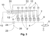
- Figure 3 illustrates another starting arrangement for an internal combustion engine including the liquid detection system of the present invention.
- the starting arrangement is in principle similar to the prior art arrangement discussed in connection with Figure 1 .
- the same reference numerals refer to the same components.
- Figure 3 the starting arrangement of a larger engine has been shown, whereby a difference, compared to the starting arrangements of Figures 1 and 2 , may be seen just upstream of the starting valves 7 where, in this case, an individual flame arrester 6 has been provided for each cylinder 3 in branch pipes 4'. Another difference can be seen in the position of the pipe 13 leading to the timing means 10.
- the starting point is that, since the engine has to be started with compressed air, the starting valves 7 are needed to deliver compressed air to the cylinders of the engine.
- timing means is electric, and the actuators of the starting valves 7 are electric, i.e. the valves 7 are solenoid valves.
- the valves 7 are solenoid valves.
- the timing means is electric
- the valve block is formed of an array of solenoid valves for connecting the pneumatic actuators of the starting valves one after another, i.e. sequentially to the compressed air source for opening the valves in a timed fashion.
- the timing means it is easy to by-pass the timing means, to switch on all solenoid valves and, thereby, to connect all actuators simultaneously to the compressed air source.
- pneumatic timing means 10 itself may be provided with means for opening a simultaneous communication from control pipe 13 to all control pipes 12.
- this optional embodiment avoids the need for a separate valve block 20.
- a small group of engine cylinders may be provided with a liquid detection means of their own.
- at least a part of the engine cylinders 3 may be provided with an individual liquid detection means (the drain valve 24, the drain pipe 28 and the liquid detector 26) arranged for instance in connection with branch pipes 4', whereby the position of the leakage may be easily located. Thereby lesser measures are needed before initiating corrective actions.
Landscapes
- Engineering & Computer Science (AREA)
- Chemical & Material Sciences (AREA)
- Combustion & Propulsion (AREA)
- Mechanical Engineering (AREA)
- General Engineering & Computer Science (AREA)
- Combined Controls Of Internal Combustion Engines (AREA)
- Fluid-Pressure Circuits (AREA)
- Output Control And Ontrol Of Special Type Engine (AREA)
- Electrical Control Of Air Or Fuel Supplied To Internal-Combustion Engine (AREA)
Description
- The present invention relates to a liquid detection system for an internal combustion engine in accordance with the preamble of claim 1, a method of operating the liquid detection system for an internal combustion engine in accordance with the preamble of the first independent method claim, and a method of upgrading an internal combustion engine with a liquid detection system in accordance with a second independent method claim.
- An internal combustion engine faces a risk of having liquid in one or more of its cylinders while starting the engine. The liquid such as water may originate not only from leakage of the cylinder head gasket, but also from leaking exhaust valve seat or leaking precombustion chamber gasket in gas engines. In case of oil leakage, the source might be a leaking diesel fuel injector or lube oil coming from injector cooling circuit or from piston cooling. The liquid present in the cylinder, i.e. in the combustion chamber increases, in the compression stage, the cylinder pressure due to its non-compressibility and, in the worst case, fills or even exceeds the volume of the combustion chamber in the top dead centre position of the piston causing a powerful pressure stroke in the cylinder, when the engine is rotated, for instance, for starting purpose. Such a pressure stroke subjects all related cylinder and engine components to failure, like for instance the cylinder head gasket, the piston, the piston rings, the piston pin, the connecting rod, its bearings, and the crank shaft and its bearings and bearing blocks.
- Thus, an object of the present invention is to provide an internal combustion engine with means for preventing engine failures due to liquid in the cylinder.
- Another object of the present invention is to provide an internal combustion engine with means for detecting the presence of liquid in a cylinder.
- A further object of the present invention is to upgrade an internal combustion engine with means for detecting the presence of liquid in at least one of its cylinders.
- A still further object of the present invention is to provide an internal combustion engine with means for reacting the presence of liquid in a cylinder, for instance by creating an alarm
-
US3572306A shows a compressed air starting device, which uses several purge valves to evacuate water from the cylinders.JP200356421 A - The above and other objects of the invention are met by a liquid detection system for an internal combustion engine, the engine being provided with an arrangement for starting the engine with compressed air, the starting arrangement comprising a source of compressed air, a master starting valve, a number of individual starting valves for at least a part of the cylinders of the engine, actuators for operating the individual starting valves, and a timing means, the at least a part of the engine cylinders being in communication with the compressed air source by means of at least the master starting valve and the individual starting valves via a pipe system having a main pipe and branch pipes, and the actuators being in communication with the timing means, the liquid detection system having additional means for rotating the engine, means for affecting the actuators for simultaneous opening of the individual starting valves, at least one drain valve arranged in one of the main pipe and at least one branch pipe, a drain pipe connected to the at least one drain valve for leading liquid from the at least a part of the cylinders out of the engine, and a liquid detector in the drain pipe.
- The above and other objects of the invention are met by a method of operating the liquid detection system for an internal combustion engine, the engine being provided with an arrangement for starting the engine with compressed air, the starting arrangement comprising a pipe system having a main pipe and branch pipes, the main pipe being connected to a source of compressed air, to a master starting valve, and by means if branch pipes to a number of individual starting valves for at least a part of the cylinders of the engine; actuators for operating the individual starting valves; and a timing means for sequentially opening and closing the individual starting valves by means of the actuators in order to rotate the engine, the liquid detection system comprising additional means for rotating the engine, means for by-passing the timing means, at least one drain valve, at least one drain pipe, and at least one liquid detector, the method comprising the steps of by-passing the timing means for opening the individual starting valves simultaneously, opening a flow communication from at least a part of the engine cylinders via the individual starting valves to the at least one drain pipe by means of the at least one drain valve, and rotating the engine slowly for discharging liquid medium from at least a part of the engine cylinders through starting valves into the at least one drain pipe.
- The above and other objects of the invention are also met by a method of upgrading an internal combustion engine with a liquid detection system, the engine being provided with an arrangement for starting the engine with compressed air, the starting arrangement comprising a pipe system having a main pipe and branch pipes, the main pipe connected to a source of compressed air, to a master starting valve, and by means of branch pipes to a number of individual starting valves for at least a part of the cylinders of the engine; actuators for operating the individual starting valves; and a timing means for sequentially opening and closing the starting valves by means of the actuators in order to rotate the engine, the method comprising the steps of providing the engine with additional means for rotating the engine, providing the starting arrangement with means for by-passing the timing means, providing at least one drain valve in the pipe system, providing the at least one drain valve with a drain pipe, and providing the drain pipe with a liquid detector.
- Other characteristic features of the present liquid detection system and the method of operating thereof will become apparent from the appended dependent claims.
- The present invention, when solving the above-mentioned problem, removes the risk of engine failure due to liquid in one or more of the engine cylinders.
- In the following, the liquid detection system for an internal combustion engine, the method of operating the liquid detection system for an internal combustion engine and the method of upgrading an internal combustion engine with a liquid detection system are explained in more detail in reference to the accompanying Figures, of which
-
Figure 1 illustrates schematically a prior art starting arrangement for an internal combustion engine, -
Figure 2 illustrates schematically a liquid detection system of the present invention arranged in connection with a prior art starting arrangement ofFigure 1 , and -
Figure 3 illustrates schematically a liquid detection system of the present invention arranged in connection with another prior art starting arrangement for an internal combustion engine. -
Figure 1 illustrates schematically the basic structures and operating principles of a prior art starting arrangement 1 of an internal combustion engine that have, for instance, been discussed in more detail inWO-A1-2007003693 the disclosure of which is incorporated as a reference herein. For starting large internal combustion engines it is customary practice to use compressed air for rotating the engine. Thesource 2 of compressed air may, for instance, be a compressed air network or a compressor. Compressed air is led to the engine via a pipe system comprising amain pipe 4 and branch pipes 4' through amaster starting valve 5 and aflame arrester 6. The compressed air is further supplied to the cylinders 3 of the internal combustion engine by means of starting valves 7, normally one starting valve 7 for each cylinder 3. However, sometimes there is no need to arrange as many starting valves as there are cylinders. For instance in V-engines there may be starting valves only on one bank of the engine. The starting valves 7 are normally arranged in connection with the cylinder head/s of the internal combustion engine so that compressed air for rotating the engine may be introduced into the combustion chamber irrespective of the position of the piston in the cylinder 3. The operation of the starting valves 7 is controlled by timing means 10, which sequentially switches on and off the connection of compressed control air frompipe 13 viapipes 12 to theactuators 8 of the starting valves 7 for sequentially opening and closing the starting valves 7. - The
master starting valve 5 of the starting arrangement 1 opens communication from thecompressed air source 2 viamain pipe 4 and the branch pipes 4' to the starting valves 7 and is pneumatically controlled by so-called control air. The control air may be received fromcompressed air source 2 or from any other appropriate source via an electrically controlled solenoid valve 9. When the flow communication from the compressed air storage is opened by the electrically operated solenoid valve 9, the compressed control air affects the stem of themaster starting valve 5, and moves the stem in such a position that a flow communication from thecompressed air source 2 to the starting valves 7 is opened through theflame arrester 6,pipe 4 and the branch pipes 4'. At the same time compressed control air fromsource 2 is led alongpipe 13 to the timing means 10. Thetiming means 10 is normally arranged in connection with the camshaft of the engine such that the operation of the timing means is synchronized with the working cycle of the engine. In a broader sense, the timing means 10 is advantageously coupled mechanically with a rotating part of the engine, whereby it enables a timely supply of compressed air to each cylinder. - A
control air pipe 12 leads from the timing means 10 to eachactuator 8 of the starting valves 7. The timing means 10 functions such that when switching on the flow communication fromline 13 to anactuator 8 of a certain starting valve 7, theactuator 8 opens the starting valve 7, whereby compressed air fromsource 2 is able to enter a cylinder 3 of the engine. The opening of the starting valve 7 of an engine cylinder 3 is timed such that the cylinder is at its working cycle and the piston has just passed its top dead center position, whereby the compressed air pushes the piston down and rotates the crank shaft in proper direction. - The
control air pipe 13 leading compressed air fromcompressed air source 8 to the timing means 10 is provided with a blockingvalve 11. The purpose of the blockingvalve 11 is to ensure that the engine cannot be started if, for instance, the engine turning gear is on. In other words, when the turning gear is on the valve stem has been pushed against the spring to the left to block the flow communication from thecompressed air source 2 to the timing means 10. -
Figure 2 illustrates a liquid detection system of the present invention arranged in connection with a prior art starting arrangement for an internal combustion engine shown inFigure 1 . Thus the same reference numerals refer to the same components. The starting arrangement illustrated inFigures 1 and2 is normally used in smaller engines where the engine is considered to manage with one flame arrester. - The liquid detection system of the present invention comprises a
valve block 20 arranged between thetiming means 10 and the starting valves 7, or actually theiractuators 8 inpipes 12. By means of thevalve block 20 it is possible to by-pass the timing means 10, i.e. to introduce compressed control air directly from the compressed air source viapipe 22 andpipes 12 to theactuators 8 of the starting valves 7 to open the valves 7 and keep them open simultaneously.Pipe 22 may be connected to any applicable compressed air source, like for instance the one shown byreference numeral 2 inFigure 1 . - The liquid detection system further comprises a
drain valve 24, which is arranged in thepipe 4 normally leading compressed air from compressed air source via branch pipes 4' and starting valves 7 to the cylinders 3. Adrain pipe 28 is connected to thedrain valve 24 to discharge medium collected from the cylinders 3. Thedrain pipe 28 is provided with aliquid detector 26, which may be arranged to give an audible or visible alarm if liquid is detected in the medium. A further option is to arrange the liquid detector to make a note in the engine log, e.g. so that afterwards it is possible to see in case of a broken engine if the engine was started after the alarm. A still further option is to arrange the liquid detector to give a signal to engine automation, if liquid is detected, for blocking the starting of the engine. Theliquid detector 26 may also initiate or perform other tasks, if such is desired. In addition to the above listed components the liquid detection system of the present invention requires means for rotating the engine. The means (not shown) for rotating the engine is preferably, but not necessarily, arranged in communication with the flywheel of the engine. The means may for instance be an electric or hydraulic motor or turning gear that is capable of slowly rotating the engine. In fact, the rotating means may correspond to a starter motor ordinarily used for starting a smaller-sized engine though its task is, preferably, to rotate the engine very slowly. Also other rotating means may be applied. - The liquid detection system of the present invention is operated before the engine is started, whereby the
master starting valve 5 blocks the entrance of compressed air to pipe 4. Firstly, thevalve block 20, for instance a series of pneumatically operating valves is arranged to by-pass the timing means 10 and to open, by means of allowing compressed control air frompipe 22 enter theactuators 8, all starting valves 7, i.e. open the communication from the cylinders 3 via branch pipes 4' to thepipe 4. Secondly,drain valve 24 is opened to arrange flow communication frompipe 4 to drainpipe 28. Thirdly, the engine is rotated slowly by the rotating means, whereby any liquid or other liquid present in the cylinders is, at least partially, pumped out toline 4. Theliquid detector 26 detects the presence of liquid in thedrain pipe 28 quickly and the control system may, if programmed in such a manner, stop the turning of the engine immediately and give an alarm, whereafter the cause for the presence of the water or liquid in one or more of the cylinders is found out, and, in the easiest case, the liquid, or at least a part of the liquid, is removed from the cylinder/s. Another alternative is to discharge the liquid manually. The root cause of the liquid leakage must, anyway, be found out, which normally requires the removal of the cylinder head. If it is a question of water leakage, and the leakage is bigger or has been there for a longer period of time, some part of the water may have gone via the gap between the piston and liner to the crankcase, whereby the water must be separated from lube oil. Thus a lot of manual work is required, but by means of the present invention the leakage is detected in time and larger damages are prevented. -
Figure 3 illustrates another starting arrangement for an internal combustion engine including the liquid detection system of the present invention. The starting arrangement is in principle similar to the prior art arrangement discussed in connection withFigure 1 . Thus the same reference numerals refer to the same components. InFigure 3 , however, the starting arrangement of a larger engine has been shown, whereby a difference, compared to the starting arrangements ofFigures 1 and2 , may be seen just upstream of the starting valves 7 where, in this case, anindividual flame arrester 6 has been provided for each cylinder 3 in branch pipes 4'. Another difference can be seen in the position of thepipe 13 leading to the timing means 10. Now thepipe 13 is just an extension ofpipe 4 taking compressed air from themaster starting valve 5 to the starting valves 7, whereas inFigures 1 and2 it was a separate pipe provided with a blocking valve. Naturally, the pipe arrangement ofFigures 1 and2 , i.e. the one including the blocking valve could be used here, too. - The liquid detection system of
Figure 3 functions and is operated in a similar manner as the one discussed above in connection withFigure 2 . - The above description discusses the timing means 10, the
valve block 20 and theactuator 8 of the starting valve 7 as pneumatic means. However, there are several options for those components. Thus, the starting point is that, since the engine has to be started with compressed air, the starting valves 7 are needed to deliver compressed air to the cylinders of the engine. - An option is that the timing means is electric, and the actuators of the starting valves 7 are electric, i.e. the valves 7 are solenoid valves. In such a case it is easy to provide the arrangement of the invention with an electric device for by-passing the timing means to open the starting valves simultaneously for operating the liquid detection system of the invention.
- Another option is that the timing means is electric, and the valve block is formed of an array of solenoid valves for connecting the pneumatic actuators of the starting valves one after another, i.e. sequentially to the compressed air source for opening the valves in a timed fashion. In case all the valves are supposed to be opened simultaneously, as is needed when practicing the invention, it is easy to by-pass the timing means, to switch on all solenoid valves and, thereby, to connect all actuators simultaneously to the compressed air source.
- Also, it should be understood that the pneumatic timing means 10 itself may be provided with means for opening a simultaneous communication from
control pipe 13 to all controlpipes 12. Thus, the use of this optional embodiment avoids the need for aseparate valve block 20. - Further, it should be understood that a small group of engine cylinders (a bank of a V- engine, for instance) may be provided with a liquid detection means of their own. In a similar manner, at least a part of the engine cylinders 3 may be provided with an individual liquid detection means (the
drain valve 24, thedrain pipe 28 and the liquid detector 26) arranged for instance in connection with branch pipes 4', whereby the position of the leakage may be easily located. Thereby lesser measures are needed before initiating corrective actions. - It should be understood that the above is only an exemplary description of a novel and inventive liquid detection system for an internal combustion engine and a method of operating the liquid detection system. It should be understood that the above description discusses only a few preferred embodiments of the present invention without any purpose to limit the invention to only the discussed embodiments and their details. Thus the above specification should not be understood as limiting the invention by any means but the entire scope of the invention is defined by the appended claims only. From the above description it should be understood that separate features of the invention may be used in connection with other separate features even if such a combination has not been specifically shown in the description or in the drawings.
Claims (10)
- A liquid detection system for an internal combustion engine, the engine being provided with an arrangement for starting the engine with compressed air, the starting arrangement comprising a source (2) of compressed air, a master starting valve (5), a number of individual starting valves (7) for at least a part of the cylinders (3) of the engine, actuators (8) for operating the individual starting valves (7), and a timing means (10), the at least a part of the engine cylinders (3) being in communication with the compressed air source (2) by means of at least the master starting valve (5) and the individual starting valves (7) via a pipe system having a main pipe (4) and branch pipes (4'), and the actuators (8) being in communication with the timing means (10), characterized in additional means for rotating the engine, means (20) for affecting the actuators (8) for simultaneous opening of the individual starting valves (7), at least one drain valve (24) arranged in one of main pipe (4) and at least one branch pipe (4'), a drain pipe (28) connected to the at least one drain valve (24) for leading liquid from the at least a part of the cylinders (3) out of the engine, and a liquid detector (26) in the drain pipe (28).
- The liquid detection system as recited in claim 1, characterized in that the timing means (10) and the actuators (8) are pneumatic, and that the means for affecting the actuators (8) is a valve block (20) for opening a communication from a compressed air source to the actuators (8) via a pipe (22) and control pipes (12).
- The liquid detection system as recited in claim 1, characterized in that the timing means (10) and the actuators (8) are pneumatic, and that the timing means (10) is provided with means for opening a simultaneous connection from control pipe (13) to all control pipes (12).
- The liquid detection system as recited in claim 1, characterized in that the timing means and the actuators are electric, whereby the means for affecting the actuators is an electric device by-passing the timing means for simultaneous operating of the actuators (8) for opening the starting valves (7).
- The liquid detection system as recited in claim 1, characterized in that the timing means is electric, the actuators (8) are pneumatic, and the means for affecting the actuators (8) is a solenoid valve block (20) for opening a communication from a compressed air source to the actuators (8) via a pipe (22) and control pipes (12).
- The liquid detection system as recited in any one of the preceding claims, characterized in means for rotating the engine slowly.
- The liquid detection system as recited in claim 6, characterized in that the rotating means is an electric or hydraulic rotation gear.
- The liquid detection system as recited in any one of the preceding claims, characterized in that the timing means (10) is arranged in connection with a rotating part of the engine, preferably with the camshaft.
- A method of operating the liquid detection system for an internal combustion engine, the engine being provided with an arrangement for starting the engine with compressed air, the starting arrangement comprising a pipe system having a main pipe (4) and branch pipes (4'), the main pipe (4) being connected to a source (2) of compressed air, to a master starting valve (5), and by means of branch pipes (4') to a number of individual starting valves (7) for at least a part of the cylinders (3) of the engine; actuators (8) for operating the individual starting valves (7); and a timing means (10) for sequentially opening and closing the individual starting valves (7) by means of the actuators (8) in order to rotate the engine, the liquid detection system comprising• additional means for rotating the engine,• means (20) for by-passing the timing means,• at least one drain valve (24),• at least one drain pipe (28), and• at least one liquid detector (26),characterized in the steps of,• by-passing the timing means (10) for opening the individual starting valves (7) simultaneously,• opening a flow communication from the at least a part of the engine cylinders (3) via the individual starting valves (7) to the at least one liquid detector (26) and drain pipe (28) by means of the at least one drain valve (24), and• rotating the engine slowly for discharging liquid medium from at least a part of the engine cylinders (3) through starting valves (7) into the at least one drain pipe (28).
- A method of upgrading an internal combustion engine with a liquid detection system, the engine being provided with an arrangement for starting the engine with compressed air, the starting arrangement comprising a pipe system having a main pipe (4) and branch pipes (4'), the main pipe (4) connected to a source (2) of compressed air, to a master starting valve (5), and by means of branch pipes (4') to a number of individual starting valves (7) for at least a part of the cylinders (3) of the engine; actuators (8) for operating the individual starting valves (7); and a timing means (10) for sequentially opening and closing the individual starting valves (7) by means of the actuators (8) in order to rotate the engine, characterized in the steps of• Providing the engine with additional means for rotating the engine,• Providing the starting arrangement with means (20) for by-passing the timing means (10),• Providing at least one drain valve (24) in the pipe system,• Providing the at least one drain valve (24) with a drain pipe (28), and• Providing the drain pipe (28) with a liquid detector (26).
Applications Claiming Priority (2)
| Application Number | Priority Date | Filing Date | Title |
|---|---|---|---|
| FI20116171A FI123333B (en) | 2011-11-23 | 2011-11-23 | Liquid detection system for an internal combustion engine, method for operating the liquid detection system and method for improving an internal combustion engine |
| PCT/FI2012/050976 WO2013076357A1 (en) | 2011-11-23 | 2012-10-11 | Compressed air starting system with a liquid detection device for an internal combustion engine, and methods thereof |
Publications (2)
| Publication Number | Publication Date |
|---|---|
| EP2783100A1 EP2783100A1 (en) | 2014-10-01 |
| EP2783100B1 true EP2783100B1 (en) | 2021-05-26 |
Family
ID=47178750
Family Applications (1)
| Application Number | Title | Priority Date | Filing Date |
|---|---|---|---|
| EP12787036.8A Active EP2783100B1 (en) | 2011-11-23 | 2012-10-11 | Compressed air starting system with a liquid detection device for an internal combustion engine, and methods thereof |
Country Status (5)
| Country | Link |
|---|---|
| EP (1) | EP2783100B1 (en) |
| KR (1) | KR101944145B1 (en) |
| CN (1) | CN104011372B (en) |
| FI (1) | FI123333B (en) |
| WO (1) | WO2013076357A1 (en) |
Families Citing this family (10)
| Publication number | Priority date | Publication date | Assignee | Title |
|---|---|---|---|---|
| WO2015132453A1 (en) * | 2014-03-07 | 2015-09-11 | Wärtsilä Finland Oy | Method and system for detecting a hydrostatic lock during the engine start |
| EP2921692B1 (en) | 2014-03-19 | 2018-08-29 | Caterpillar Motoren GmbH & Co. KG | Internal combustion engine with starting air system |
| WO2016193527A1 (en) * | 2015-06-03 | 2016-12-08 | Wärtsilä Finland Oy | An internal combustion piston engine, a method of starting an internal combustion piston engine and a control unit |
| RU2612516C1 (en) * | 2016-03-31 | 2017-03-09 | Евгений Александрович Оленев | Device for starting tank engine |
| CN105781843A (en) * | 2016-05-17 | 2016-07-20 | 陕西柴油机重工有限公司 | Starting system and starting method for gas engine |
| DE102016012403B4 (en) * | 2016-10-17 | 2018-11-08 | Mtu Friedrichshafen Gmbh | Method for starting an internal combustion engine |
| CN110529248B (en) * | 2019-10-09 | 2023-10-27 | 河南柴油机重工有限责任公司 | Air distribution starting system for high-speed diesel engine |
| CN112881022B (en) * | 2019-11-29 | 2025-09-16 | 中国船舶集团有限公司第七一一研究所 | Test platform and control method of diesel engine starting system |
| CN112696281A (en) * | 2020-12-28 | 2021-04-23 | 潍柴动力股份有限公司 | Control method, device and system for automatic slow turning of large diesel engine |
| CN113719390B (en) * | 2021-09-07 | 2022-12-06 | 中船动力研究院有限公司 | Redundant starting diesel engine and control method thereof |
Family Cites Families (11)
| Publication number | Priority date | Publication date | Assignee | Title |
|---|---|---|---|---|
| CH491290A (en) * | 1968-05-10 | 1970-05-31 | Nova Werke Ferber & Wran | Compressed air starter system for diesel engines with a device for draining the water from the cylinders before starting |
| US3667442A (en) * | 1970-02-16 | 1972-06-06 | White Sales Corp Graham | Pneumatic starting system for diesel engines |
| DE2632015A1 (en) | 1976-07-16 | 1978-01-19 | Motoren Turbinen Union | DIESEL COMBUSTION ENGINE |
| JPS58222974A (en) * | 1982-06-22 | 1983-12-24 | Ishikawajima Harima Heavy Ind Co Ltd | Starting air controller of diesel engine |
| JPS59131766A (en) * | 1983-01-18 | 1984-07-28 | Komatsu Ltd | Construction vehicle engine starting device |
| JPS61288369A (en) * | 1985-06-14 | 1986-12-18 | Matsushita Electric Ind Co Ltd | sealed battery |
| JP4364463B2 (en) * | 2001-08-09 | 2009-11-18 | ヤンマー株式会社 | Internal combustion engine having a mechanism for preventing water hammer |
| FI119703B (en) | 2005-07-01 | 2009-02-13 | Waertsilae Finland Oy | Starting device for a piston engine operating with pressure medium |
| AT506561B1 (en) * | 2009-05-07 | 2011-05-15 | Avl List Gmbh | METHOD FOR STARTING A COMBUSTION ENGINE POWERED BY INTERNAL COMBUSTION ENGINE |
| CN201650458U (en) * | 2010-04-23 | 2010-11-24 | 中国北车集团大连机车车辆有限公司 | Diesel Engine Anti-Oil Water Hammer Fault Alarm Device |
| CN101984245A (en) * | 2010-11-12 | 2011-03-09 | 西南交通大学 | Automobile wading anti-flameout structure |
-
2011
- 2011-11-23 FI FI20116171A patent/FI123333B/en not_active IP Right Cessation
-
2012
- 2012-10-11 CN CN201280057607.2A patent/CN104011372B/en active Active
- 2012-10-11 WO PCT/FI2012/050976 patent/WO2013076357A1/en not_active Ceased
- 2012-10-11 KR KR1020147017123A patent/KR101944145B1/en active Active
- 2012-10-11 EP EP12787036.8A patent/EP2783100B1/en active Active
Non-Patent Citations (1)
| Title |
|---|
| None * |
Also Published As
| Publication number | Publication date |
|---|---|
| FI123333B (en) | 2013-02-28 |
| EP2783100A1 (en) | 2014-10-01 |
| KR20140097431A (en) | 2014-08-06 |
| KR101944145B1 (en) | 2019-01-30 |
| CN104011372B (en) | 2016-06-08 |
| CN104011372A (en) | 2014-08-27 |
| FI20116171A7 (en) | 2013-02-28 |
| WO2013076357A1 (en) | 2013-05-30 |
Similar Documents
| Publication | Publication Date | Title |
|---|---|---|
| FI123333B (en) | Liquid detection system for an internal combustion engine, method for operating the liquid detection system and method for improving an internal combustion engine | |
| EP3686413B1 (en) | Engine overspeed shutdown systems and methods | |
| CN1690374B (en) | Internal combustion engine with cylinder lubrication system | |
| JP2009150291A (en) | Blow-by gas recirculation device | |
| EP3101266B1 (en) | Malfunction diagnosis device and malfunction diagnosis method for internal combustion engine system | |
| EP3245394B1 (en) | A method of controlling an operation of an inlet valve system and an inlet valve control system | |
| EP3303795B1 (en) | An internal combustion piston engine, a method of starting an internal combustion piston engine and a control unit | |
| JPH04318253A (en) | Multicylinder engine | |
| JP2015218643A (en) | Engine control device | |
| EP2766708B1 (en) | An arrangement for and a method of taking a sample of lubrication oil in an internal combustion piston engine | |
| JPH0727379Y2 (en) | In-cylinder condition diagnosis device when the engine is stopped | |
| EP3201447B1 (en) | Two-stroke opposed-piston engine with compression release | |
| JP2003056421A (en) | Internal combustion engine with mechanism for preventing water hammer | |
| JP2011021499A (en) | Internal combustion engine and method for controlling the same | |
| JP5282679B2 (en) | Internal combustion engine and control method thereof | |
| US20220195913A1 (en) | Air feed system for an internal combustion engine | |
| SU1451583A1 (en) | Method of testing an i.c. engine | |
| JP6051508B2 (en) | Abnormal combustion prevention system for diesel engine | |
| US20150082781A1 (en) | Pneumatic system for engines | |
| EP3114341A1 (en) | Method and system for detecting a hydrostatic lock during the engine start |
Legal Events
| Date | Code | Title | Description |
|---|---|---|---|
| PUAI | Public reference made under article 153(3) epc to a published international application that has entered the european phase |
Free format text: ORIGINAL CODE: 0009012 |
|
| 17P | Request for examination filed |
Effective date: 20140515 |
|
| AK | Designated contracting states |
Kind code of ref document: A1 Designated state(s): AL AT BE BG CH CY CZ DE DK EE ES FI FR GB GR HR HU IE IS IT LI LT LU LV MC MK MT NL NO PL PT RO RS SE SI SK SM TR |
|
| DAX | Request for extension of the european patent (deleted) | ||
| RAP1 | Party data changed (applicant data changed or rights of an application transferred) |
Owner name: WAERTSILAE FINLAND OY |
|
| GRAP | Despatch of communication of intention to grant a patent |
Free format text: ORIGINAL CODE: EPIDOSNIGR1 |
|
| STAA | Information on the status of an ep patent application or granted ep patent |
Free format text: STATUS: GRANT OF PATENT IS INTENDED |
|
| RIC1 | Information provided on ipc code assigned before grant |
Ipc: F02N 15/10 20060101ALI20201113BHEP Ipc: F02N 9/04 20060101AFI20201113BHEP |
|
| INTG | Intention to grant announced |
Effective date: 20201218 |
|
| GRAS | Grant fee paid |
Free format text: ORIGINAL CODE: EPIDOSNIGR3 |
|
| GRAA | (expected) grant |
Free format text: ORIGINAL CODE: 0009210 |
|
| STAA | Information on the status of an ep patent application or granted ep patent |
Free format text: STATUS: THE PATENT HAS BEEN GRANTED |
|
| AK | Designated contracting states |
Kind code of ref document: B1 Designated state(s): AL AT BE BG CH CY CZ DE DK EE ES FI FR GB GR HR HU IE IS IT LI LT LU LV MC MK MT NL NO PL PT RO RS SE SI SK SM TR |
|
| REG | Reference to a national code |
Ref country code: GB Ref legal event code: FG4D |
|
| REG | Reference to a national code |
Ref country code: CH Ref legal event code: EP |
|
| REG | Reference to a national code |
Ref country code: AT Ref legal event code: REF Ref document number: 1396463 Country of ref document: AT Kind code of ref document: T Effective date: 20210615 |
|
| REG | Reference to a national code |
Ref country code: DE Ref legal event code: R096 Ref document number: 602012075692 Country of ref document: DE |
|
| REG | Reference to a national code |
Ref country code: IE Ref legal event code: FG4D |
|
| REG | Reference to a national code |
Ref country code: LT Ref legal event code: MG9D |
|
| REG | Reference to a national code |
Ref country code: AT Ref legal event code: MK05 Ref document number: 1396463 Country of ref document: AT Kind code of ref document: T Effective date: 20210526 |
|
| PG25 | Lapsed in a contracting state [announced via postgrant information from national office to epo] |
Ref country code: LT Free format text: LAPSE BECAUSE OF FAILURE TO SUBMIT A TRANSLATION OF THE DESCRIPTION OR TO PAY THE FEE WITHIN THE PRESCRIBED TIME-LIMIT Effective date: 20210526 Ref country code: FI Free format text: LAPSE BECAUSE OF FAILURE TO SUBMIT A TRANSLATION OF THE DESCRIPTION OR TO PAY THE FEE WITHIN THE PRESCRIBED TIME-LIMIT Effective date: 20210526 Ref country code: HR Free format text: LAPSE BECAUSE OF FAILURE TO SUBMIT A TRANSLATION OF THE DESCRIPTION OR TO PAY THE FEE WITHIN THE PRESCRIBED TIME-LIMIT Effective date: 20210526 Ref country code: AT Free format text: LAPSE BECAUSE OF FAILURE TO SUBMIT A TRANSLATION OF THE DESCRIPTION OR TO PAY THE FEE WITHIN THE PRESCRIBED TIME-LIMIT Effective date: 20210526 Ref country code: BG Free format text: LAPSE BECAUSE OF FAILURE TO SUBMIT A TRANSLATION OF THE DESCRIPTION OR TO PAY THE FEE WITHIN THE PRESCRIBED TIME-LIMIT Effective date: 20210826 |
|
| REG | Reference to a national code |
Ref country code: NL Ref legal event code: MP Effective date: 20210526 |
|
| PG25 | Lapsed in a contracting state [announced via postgrant information from national office to epo] |
Ref country code: PL Free format text: LAPSE BECAUSE OF FAILURE TO SUBMIT A TRANSLATION OF THE DESCRIPTION OR TO PAY THE FEE WITHIN THE PRESCRIBED TIME-LIMIT Effective date: 20210526 Ref country code: PT Free format text: LAPSE BECAUSE OF FAILURE TO SUBMIT A TRANSLATION OF THE DESCRIPTION OR TO PAY THE FEE WITHIN THE PRESCRIBED TIME-LIMIT Effective date: 20210927 Ref country code: NO Free format text: LAPSE BECAUSE OF FAILURE TO SUBMIT A TRANSLATION OF THE DESCRIPTION OR TO PAY THE FEE WITHIN THE PRESCRIBED TIME-LIMIT Effective date: 20210826 Ref country code: RS Free format text: LAPSE BECAUSE OF FAILURE TO SUBMIT A TRANSLATION OF THE DESCRIPTION OR TO PAY THE FEE WITHIN THE PRESCRIBED TIME-LIMIT Effective date: 20210526 Ref country code: SE Free format text: LAPSE BECAUSE OF FAILURE TO SUBMIT A TRANSLATION OF THE DESCRIPTION OR TO PAY THE FEE WITHIN THE PRESCRIBED TIME-LIMIT Effective date: 20210526 Ref country code: GR Free format text: LAPSE BECAUSE OF FAILURE TO SUBMIT A TRANSLATION OF THE DESCRIPTION OR TO PAY THE FEE WITHIN THE PRESCRIBED TIME-LIMIT Effective date: 20210827 Ref country code: IS Free format text: LAPSE BECAUSE OF FAILURE TO SUBMIT A TRANSLATION OF THE DESCRIPTION OR TO PAY THE FEE WITHIN THE PRESCRIBED TIME-LIMIT Effective date: 20210926 Ref country code: LV Free format text: LAPSE BECAUSE OF FAILURE TO SUBMIT A TRANSLATION OF THE DESCRIPTION OR TO PAY THE FEE WITHIN THE PRESCRIBED TIME-LIMIT Effective date: 20210526 |
|
| PG25 | Lapsed in a contracting state [announced via postgrant information from national office to epo] |
Ref country code: NL Free format text: LAPSE BECAUSE OF FAILURE TO SUBMIT A TRANSLATION OF THE DESCRIPTION OR TO PAY THE FEE WITHIN THE PRESCRIBED TIME-LIMIT Effective date: 20210526 |
|
| PG25 | Lapsed in a contracting state [announced via postgrant information from national office to epo] |
Ref country code: CZ Free format text: LAPSE BECAUSE OF FAILURE TO SUBMIT A TRANSLATION OF THE DESCRIPTION OR TO PAY THE FEE WITHIN THE PRESCRIBED TIME-LIMIT Effective date: 20210526 Ref country code: EE Free format text: LAPSE BECAUSE OF FAILURE TO SUBMIT A TRANSLATION OF THE DESCRIPTION OR TO PAY THE FEE WITHIN THE PRESCRIBED TIME-LIMIT Effective date: 20210526 Ref country code: DK Free format text: LAPSE BECAUSE OF FAILURE TO SUBMIT A TRANSLATION OF THE DESCRIPTION OR TO PAY THE FEE WITHIN THE PRESCRIBED TIME-LIMIT Effective date: 20210526 Ref country code: SM Free format text: LAPSE BECAUSE OF FAILURE TO SUBMIT A TRANSLATION OF THE DESCRIPTION OR TO PAY THE FEE WITHIN THE PRESCRIBED TIME-LIMIT Effective date: 20210526 Ref country code: SK Free format text: LAPSE BECAUSE OF FAILURE TO SUBMIT A TRANSLATION OF THE DESCRIPTION OR TO PAY THE FEE WITHIN THE PRESCRIBED TIME-LIMIT Effective date: 20210526 Ref country code: RO Free format text: LAPSE BECAUSE OF FAILURE TO SUBMIT A TRANSLATION OF THE DESCRIPTION OR TO PAY THE FEE WITHIN THE PRESCRIBED TIME-LIMIT Effective date: 20210526 Ref country code: ES Free format text: LAPSE BECAUSE OF FAILURE TO SUBMIT A TRANSLATION OF THE DESCRIPTION OR TO PAY THE FEE WITHIN THE PRESCRIBED TIME-LIMIT Effective date: 20210526 |
|
| REG | Reference to a national code |
Ref country code: DE Ref legal event code: R097 Ref document number: 602012075692 Country of ref document: DE |
|
| PLBE | No opposition filed within time limit |
Free format text: ORIGINAL CODE: 0009261 |
|
| STAA | Information on the status of an ep patent application or granted ep patent |
Free format text: STATUS: NO OPPOSITION FILED WITHIN TIME LIMIT |
|
| 26N | No opposition filed |
Effective date: 20220301 |
|
| REG | Reference to a national code |
Ref country code: CH Ref legal event code: PL |
|
| PG25 | Lapsed in a contracting state [announced via postgrant information from national office to epo] |
Ref country code: IS Free format text: LAPSE BECAUSE OF FAILURE TO SUBMIT A TRANSLATION OF THE DESCRIPTION OR TO PAY THE FEE WITHIN THE PRESCRIBED TIME-LIMIT Effective date: 20210926 Ref country code: AL Free format text: LAPSE BECAUSE OF FAILURE TO SUBMIT A TRANSLATION OF THE DESCRIPTION OR TO PAY THE FEE WITHIN THE PRESCRIBED TIME-LIMIT Effective date: 20210526 |
|
| REG | Reference to a national code |
Ref country code: BE Ref legal event code: MM Effective date: 20211031 |
|
| GBPC | Gb: european patent ceased through non-payment of renewal fee |
Effective date: 20211011 |
|
| PG25 | Lapsed in a contracting state [announced via postgrant information from national office to epo] |
Ref country code: MC Free format text: LAPSE BECAUSE OF FAILURE TO SUBMIT A TRANSLATION OF THE DESCRIPTION OR TO PAY THE FEE WITHIN THE PRESCRIBED TIME-LIMIT Effective date: 20210526 |
|
| PG25 | Lapsed in a contracting state [announced via postgrant information from national office to epo] |
Ref country code: LU Free format text: LAPSE BECAUSE OF NON-PAYMENT OF DUE FEES Effective date: 20211011 Ref country code: IT Free format text: LAPSE BECAUSE OF FAILURE TO SUBMIT A TRANSLATION OF THE DESCRIPTION OR TO PAY THE FEE WITHIN THE PRESCRIBED TIME-LIMIT Effective date: 20210526 Ref country code: GB Free format text: LAPSE BECAUSE OF NON-PAYMENT OF DUE FEES Effective date: 20211011 Ref country code: BE Free format text: LAPSE BECAUSE OF NON-PAYMENT OF DUE FEES Effective date: 20211031 |
|
| PG25 | Lapsed in a contracting state [announced via postgrant information from national office to epo] |
Ref country code: LI Free format text: LAPSE BECAUSE OF NON-PAYMENT OF DUE FEES Effective date: 20211031 Ref country code: CH Free format text: LAPSE BECAUSE OF NON-PAYMENT OF DUE FEES Effective date: 20211031 |
|
| PG25 | Lapsed in a contracting state [announced via postgrant information from national office to epo] |
Ref country code: FR Free format text: LAPSE BECAUSE OF NON-PAYMENT OF DUE FEES Effective date: 20211031 |
|
| PG25 | Lapsed in a contracting state [announced via postgrant information from national office to epo] |
Ref country code: IE Free format text: LAPSE BECAUSE OF NON-PAYMENT OF DUE FEES Effective date: 20211011 |
|
| PG25 | Lapsed in a contracting state [announced via postgrant information from national office to epo] |
Ref country code: HU Free format text: LAPSE BECAUSE OF FAILURE TO SUBMIT A TRANSLATION OF THE DESCRIPTION OR TO PAY THE FEE WITHIN THE PRESCRIBED TIME-LIMIT; INVALID AB INITIO Effective date: 20121011 Ref country code: CY Free format text: LAPSE BECAUSE OF FAILURE TO SUBMIT A TRANSLATION OF THE DESCRIPTION OR TO PAY THE FEE WITHIN THE PRESCRIBED TIME-LIMIT Effective date: 20210526 |
|
| PG25 | Lapsed in a contracting state [announced via postgrant information from national office to epo] |
Ref country code: MK Free format text: LAPSE BECAUSE OF FAILURE TO SUBMIT A TRANSLATION OF THE DESCRIPTION OR TO PAY THE FEE WITHIN THE PRESCRIBED TIME-LIMIT Effective date: 20210526 |
|
| PG25 | Lapsed in a contracting state [announced via postgrant information from national office to epo] |
Ref country code: TR Free format text: LAPSE BECAUSE OF FAILURE TO SUBMIT A TRANSLATION OF THE DESCRIPTION OR TO PAY THE FEE WITHIN THE PRESCRIBED TIME-LIMIT Effective date: 20210526 |
|
| PG25 | Lapsed in a contracting state [announced via postgrant information from national office to epo] |
Ref country code: MT Free format text: LAPSE BECAUSE OF FAILURE TO SUBMIT A TRANSLATION OF THE DESCRIPTION OR TO PAY THE FEE WITHIN THE PRESCRIBED TIME-LIMIT Effective date: 20210526 |
|
| PGFP | Annual fee paid to national office [announced via postgrant information from national office to epo] |
Ref country code: DE Payment date: 20251021 Year of fee payment: 14 |