EP2782416A1 - Tubular heater and heating device - Google Patents
Tubular heater and heating device Download PDFInfo
- Publication number
- EP2782416A1 EP2782416A1 EP20120849842 EP12849842A EP2782416A1 EP 2782416 A1 EP2782416 A1 EP 2782416A1 EP 20120849842 EP20120849842 EP 20120849842 EP 12849842 A EP12849842 A EP 12849842A EP 2782416 A1 EP2782416 A1 EP 2782416A1
- Authority
- EP
- European Patent Office
- Prior art keywords
- glass tube
- filament
- tubular heater
- anchors
- tube
- Prior art date
- Legal status (The legal status is an assumption and is not a legal conclusion. Google has not performed a legal analysis and makes no representation as to the accuracy of the status listed.)
- Withdrawn
Links
Images


Classifications
-
- H—ELECTRICITY
- H05—ELECTRIC TECHNIQUES NOT OTHERWISE PROVIDED FOR
- H05B—ELECTRIC HEATING; ELECTRIC LIGHT SOURCES NOT OTHERWISE PROVIDED FOR; CIRCUIT ARRANGEMENTS FOR ELECTRIC LIGHT SOURCES, IN GENERAL
- H05B3/00—Ohmic-resistance heating
- H05B3/0033—Heating devices using lamps
- H05B3/0038—Heating devices using lamps for industrial applications
-
- G—PHYSICS
- G03—PHOTOGRAPHY; CINEMATOGRAPHY; ANALOGOUS TECHNIQUES USING WAVES OTHER THAN OPTICAL WAVES; ELECTROGRAPHY; HOLOGRAPHY
- G03G—ELECTROGRAPHY; ELECTROPHOTOGRAPHY; MAGNETOGRAPHY
- G03G15/00—Apparatus for electrographic processes using a charge pattern
- G03G15/20—Apparatus for electrographic processes using a charge pattern for fixing, e.g. by using heat
- G03G15/2003—Apparatus for electrographic processes using a charge pattern for fixing, e.g. by using heat using heat
- G03G15/2014—Apparatus for electrographic processes using a charge pattern for fixing, e.g. by using heat using heat using contact heat
- G03G15/2053—Structural details of heat elements, e.g. structure of roller or belt, eddy current, induction heating
-
- H—ELECTRICITY
- H01—ELECTRIC ELEMENTS
- H01K—ELECTRIC INCANDESCENT LAMPS
- H01K1/00—Details
- H01K1/18—Mountings or supports for the incandescent body
-
- H—ELECTRICITY
- H01—ELECTRIC ELEMENTS
- H01K—ELECTRIC INCANDESCENT LAMPS
- H01K1/00—Details
- H01K1/18—Mountings or supports for the incandescent body
- H01K1/24—Mounts for lamps with connections at opposite ends, e.g. for tubular lamp
Definitions
- An embodiment of the present invention relates to a tubular heater and a heating apparatus used in manufacture of solar batteries, molding of plastic bottles, heaters, copying machines, fixation of toner in printers, and the like.
- a tubular heater has a structure in which a filament is arranged in an interior of a cylindrical glass tube.
- the filament is arranged so as to be positioned at a center of the glass tube by an anchor formed by winding a metal wire.
- a plurality of such anchors are provided along a direction of a tube axis of the glass tube.
- the number of the anchors is extremely large, and an increase of an amount of usage of the metal wire for the anchors accelerates an influence of an increased weight or costs.
- Patent Literature 1 JP-A-H05-082106
- a tubular heater of an embodiment includes: an elongated glass tube; a filament arranged so as to extend along a tube axis in an interior of the glass tube; and a plurality of anchors mounted on the filament, wherein the anchor includes an engaging portion connected to the filament, an extending portion connected at one end thereof to the engaging portion and extending at the other end thereof in a direction of a tube wall of the glass tube, and a holding portion formed so as to extend from the other end of the extending portion along the tube wall and configured to hold the filament with respect to the glass tube by coming into contact with the tube wall, and the holding portion has a center angle ⁇ at a center C of the glass tube satisfying a relationship of 180° ⁇ ⁇ ⁇ 360°.
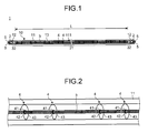
- FIG. 1 is a drawing for explaining the tubular heater of the first embodiment
- Fig. 2 is a drawing for explaining part of the tubular heater of the first embodiment
- Fig. 3 is a drawing for explaining a cross section of the tubular heater of the first embodiment.
- a tubular heater 1 includes a glass tube 10 formed of, for example, quartz glass as a principal portion.
- the glass tube 10 is an elongated tube having an entire length of, for example, 1900 mm, and includes a cylindrical portion 11 and seal portions 12.
- the cylindrical portion 11 is a cylindrical portion having an outer diameter, which occupies a major part of the glass tube 10, of 12 mm for example.
- Part of the cylindrical portion includes a chip 111 used for performing exhausting and gas introduction from and to the interior of the glass tube 10 formed thereon.
- the seal portions 12 are plate-shaped sealing portions having a width of, for example, 12.5 mm and are formed at both ends of the cylindrical portion 11 by pinch sealing.
- the seal portions 12 may be formed into a cylindrical shape formed by shrink sealing.
- a space 13 is formed in the interior of the glass tube 10.
- the space 13 is filled with, for example, a minute amount of halogen substance such as bromine, or iodine, or gas such as argon, neon, or nitrogen encapsulated therein.
- Metal foils 2 are sealed in the interiors of the seal portions 12.
- the metal foils 2 are thin plates formed of, for example, molybdenum, and are arranged so as to extend along plate-shaped planes of the seal portions 12.
- a filament 3 is provided in the interior of the glass tube 10.
- the filament 3 is a metal wire formed of, for example, tungsten, and includes a main portion 31 and leg portions 32.
- the main portion 31 is a portion that generates heat when being illuminated, and the length thereof is, for example, 1800 mm.
- the main portion 31 is arranged in the space 13.
- the leg portions 32 are portions that feed power to the main portion 31, are arranged at both ends of the main portion 31, and are connected to the metal foils 2.
- Anchors 4 are provided as support members in the interior of the glass tube 10.
- the anchor 4 is a metal wire formed of, for example, tungsten, and includes an engaging portion 41, an extending portion 42, and a holding portion 43 .
- the engaging portion 41 is a portion to be connected to the main portion 31 of the filament 3, and is wound around the periphery of the main portion 31 by several turns.
- the extending portion 42 is a portion formed by an end of the engaging portion 41, and extends toward a tube wall of the cylindrical portion 11 of the glass tube 10.
- the holding portion 43 is a portion formed of the other end of the extending portion 42, and is provided so as to extend from the extending portion 42 in the vicinity of the tube wall along a tube wall surface.
- a plurality of the anchors 4 are provided in a direction of a tube axis so as to maintain a first pitch (approximately 16 mm) and a second pitch (approximately 29 mm), and support the main portion 31 of the filament 3 so as to be positioned at a substantially center of the space 13.
- the lead wires 5 are connected to sides of the metal foils 2 on which the leg portions 32 are not connected.
- the lead wires 5 are metal wires formed of, for example, molybdenum, tungsten, or the like, and the ends on other side are drawn out from the seal portions 12 so as to extend the tube axis.
- the holding portion 43 of the anchor 4 of this embodiment is an arc having a range of the holding portion 43 with respect to a center C (center angle ⁇ ) satisfying a relationship of 180° ⁇ ⁇ ⁇ 360°, where a center of the cylindrical portion 11 of the glass tube 10 is C.
- a center of the cylindrical portion 11 of the glass tube 10 is C.
- it is a major arc having the center angle ⁇ of 270°.
- a free end side of the holding portion 43 does not reach a fixed end side, that is, a boundary portion 44 between the extending portion 42 and the holding portion 43.
- the plurality of such anchors 4 are provided along the tube axis.
- the center angle ⁇ of 90° is not sufficient to achieve the holding function of the filament 3, but the center angle ⁇ of 180° or more does not cause any specific problem in the holding function.
- the reason when the holding function is not sufficient when the center angle ⁇ is 90° is that there is a case where the holding portion 43 can hardly come into contact with an inner wall of the glass tube.
- the holding portion 43 preferably has the center angle ⁇ at the center C of the cylindrical portion 11 satisfying a relationship of 180° ⁇ ⁇ ⁇ 360°.
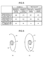
- Fig. 5 is a drawing for explaining temperatures of upper portions and lower portions of the glass tube in the tubular heaters of Example 2 and the related art.
- Example 2 is a tubular heater having a plurality of anchors having the center angle ⁇ of 180° as illustrated in Fig. 6(a)
- the related art is a tubular heater having a plurality of anchors having the center angle ⁇ of 360° as illustrated in Fig. 6(b) , both arranged in the direction of the tube axis in the same orientation.
- the temperature is measured by using a thermoviewer.
- Example 2 the temperature difference between the upper portion and the lower portion of the cylindrical portion 11 is larger in Example 2 than in the related art. More specifically, although the temperature is high at the glass tube wall in the vicinity of the boundary portion 44, which corresponds to a boundary portion between the extending portion 42 and the holding portion 43 and the temperature of the glass tube wall on the opposite side is low both in Example 2 and in the related art consequently, such a temperature difference is larger in Example 2.
- the reason why the temperature difference is larger when the boundary portion 44 faces downward than when facing upward is that the boundary portion 44 comes into contact with the inner wall of the glass when facing downward by the gravitational force, so that the lower side of the glass tube 10 can easily be heated.
- a certain portion may be heated intensively or, in contrast, cooled down, or heated to enhance the uniformity of the temperature depending on arrangements of the boundary portion 44.
- the same result as illustrated in Fig. 5 is obtained when the center angle ⁇ is in a range of 180° ⁇ ⁇ ⁇ 360°.
- the holding portion 43 is formed so that the center angle ⁇ at the center C of the cylindrical portion 11 satisfies a relationship of 180° ⁇ ⁇ ⁇ 360°, a total amount of usage of the metal wire that constitutes the anchors 4 may be significantly reduced while maintaining the filament 3 sufficiently.
- the temperature difference may be generated between the boundary portion 44 which corresponds to the other end of the extending portion 42 and the glass tube wall on the side opposite thereto, intensive heating, or inversely, lowering of the temperature, and heating with higher uniformity of temperature are enabled by utilizing the characteristic thereof.
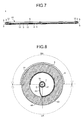
- Fig. 7 is a drawing for explaining the tubular heater of a second embodiment.
- components which are the same as the components of the tubular heater of the first embodiment are denoted by the same reference numerals, and the description thereof is omitted.
- a reflecting film 6 is formed along the tube axis on part of an outer surface of the cylindrical portion 11 of the glass tube 10.
- the reflecting film 6 is a reflecting film presenting with white color formed of oxidation products such as silica or alumina by a method of dipping, blowing, or the like.
- the range of formation thereof on the circumference of the cylindrical portion 11 is, as illustrated in Fig. 8 , for example, 180°, but may be varied within a range of 90° to 300° depending on the object.
- the boundary portion 44 of the anchor 4 is not positioned in a reflecting area RA of the glass tube 10 where the reflecting film 6 is formed, but on an irradiating area LA side, which is an area other than the reflecting area RA.
- the reflecting film 6 has a lower heat resistivity in comparison with the glass tube 10, which is formed of quartz glass, and when the temperature is increased to a high temperature, the reflecting film 6 is liable to be separated from the glass tube 10. Therefore, a low temperature is preferable.
- the opening side of the glass tube 10 on which the reflecting film 6 is not formed is a side that heats an object to be irradiated. Therefore, the higher temperature is preferable so as to cause a heating effect by conduction and convection in addition to heating with an infrared ray.
- the temperature of the glass tube wall in the vicinity of the boundary portion 44 is liable to be high and the temperature on the opposite side is liable to be low. Therefore, in this configuration, enhancement of the heating efficiency is achieved while suppressing separation of the reflecting film 6.
- the reflecting film 6 when the reflecting film 6 is formed on an outer surface of the glass tube 10, and an area of the glass tube 10 formed with the reflecting film 6 on the circumference of the glass tube 10 is defined as the reflecting area RA and an area other than that is defined as the irradiating area LA, enhancement of the heating efficiency is achieved while suppressing separation of the reflecting film 6 by the arrangement of the boundary portion 44 of the anchor 4 on the irradiating area LA side.
- Fig. 9 is a drawing for explaining a heating apparatus of a third embodiment.
- a fixing apparatus includes a housing 7 and the tubular heater 1.
- the housing 7 is a case formed of, for example, stainless steel, and includes a wall portion 71 and a side wall portion 72 connected to an end side thereof. An opening portion 73 is provided on the side opposing the wall portion 71.
- the tubular heater 1 is a heater which is the same as that of the first embodiment, and a plurality of the tubular heaters 1 are arranged in an internal space of the housing 7 so that the tube axes extend in substantially parallel to each other.
- the tubular heaters 1 are each positioned so that the boundary portion 44 of the anchor 4 is arranged in the reflecting area RA, which is an area opposing the wall portion 71, and is not positioned in the irradiating area LA which is an area opposing the opening portion 73.
- portions immediately below the tubular heaters 1 are liable to be a high temperature, and portions immediately under parts between the adjacent tubular heaters 1 are liable to be a low temperature.
- the temperature immediately below may be lowered, and hence unevenness of the temperature of the object to be irradiated may be alleviated.
- the temperature of the object to be irradiated may be uniformized by arranging the tubular heaters 1 so that the boundary portion 44 of the anchor 4 faces toward the wall portion 71.
- the tubular heaters 1 may be arranged so that the boundary portion 44 faces the direction of the opening portion 73.
- the main portion 31 of the filament 3 is formed into a coil-shaped portion as a whole, there may be provided a non-light-emitting portion, which has a simple linear shape, at a midsection thereof.
- the holding portion 43 of the anchor 4 may be provided on the coil-shaped portion.
- the number of the anchors 4 to be mounted on the respective coil-shaped portions may be one or plural.
- the holding portion 43 is not limited to an arc shape, and polygonal shapes such as a triangle shape and a square shape are also applicable. In other words, corner portions thereof may be brought into contact with the inner wall surface of the glass tube 10. In this shape, the amount of usage of the metal wire for the anchors 4 may further be reduced in comparison with a circular shape.
- All of the boundary portions 44 from among the plurality of anchors 4 do not necessarily have to face the same direction, and some may face different directions as long as it is within an extent of variations or several tens percent of the entire part.
- what is essential is that more than half the plurality of anchors 4 are arranged so that the boundary portions 44 are positioned in the irradiating area LA in the second embodiment and in the reflecting area RA in the third embodiment.
- controlling all the anchors 4 so as to face substantially the same direction is optimal in terms of suppression of transfer of heat to the reflecting film 6 or suppression of non-uniformity of the temperature to the object to be irradiated.
- the direction of the boundary portions 44 may be at random. In this arrangement, such an event that areas where the filament 3 cannot be supported by the anchor 4 are generated continuously and hence the filament 3 is deflected may be prevented.
- the range of the holding portion 43 with respect to the center C is formed into an arc that satisfies a relationship of 180° ⁇ ⁇ ⁇ 360°, an arc that satisfies a relationship of 225° ⁇ ⁇ ⁇ 315° is more preferable.
- the center angle ⁇ is set to 225° or more because there is a case where the deflection under the weight of the filament 3 of its own cannot be sufficiently suppressed if the holding portion 43 does not exist below when the tubular heater 1 is arranged horizontally when the center angle ⁇ is 180°.
- the center angle ⁇ is set to 315° or smaller in order to obtain an effect of increasing a temperature difference to be larger than that with the tubular heater of the related art at the tube wall of the cylindrical portion 11 when illuminating in consideration of variations at the time of manufacture of the anchor 4 because the center angle ⁇ may become 360° or more due to variations at the time of manufacture of the anchor 4 when the center angle ⁇ is smaller than 360° but near 360°.
- the tubular heater 1 when arranging the tubular heater 1 horizontally, the tubular heater 1 is arranged so that the boundary portion 44 of each of the anchors 4 faces downward.
- the anchors 4 are each arranged so that an opening portion between free ends of the boundary portion 44 and the holding portion 43 faces upward. Accordingly, the filament 3 trying to be deflected under its own weight may be reliably held by the anchors 4.
- a wire diameter d of each of the anchors 4 is preferably increased in thickness so as to hold the filament 3 reliably.
- the wire diameter d of each of the anchors 4 is preferably 0.32 mm or larger, more preferably, 0.36 mm or larger.
- a holding force with respect to the filament 3 may be increased, whereby the filament 3 may be reliably held by the anchors 4.
- the wire diameter of each of the anchors 4 is preferably 0.42 mm or lower.
- the density of arrangement of the respective anchors 4 with respect to the filament 3 is preferably set to a high density in order to hold the filament 3 reliably.
- the wiring density of L/n is preferably set to 17 mm/piece or lower, more preferably 14 mm/piece or lower, where L is a length of the main portion 31 of the filament 3 (see Fig. 1 ) , and n is the number of the anchors 4 provided for the length L.
Landscapes
- Physics & Mathematics (AREA)
- General Physics & Mathematics (AREA)
- Resistance Heating (AREA)
- Control Of Resistance Heating (AREA)
Abstract
Description
- An embodiment of the present invention relates to a tubular heater and a heating apparatus used in manufacture of solar batteries, molding of plastic bottles, heaters, copying machines, fixation of toner in printers, and the like.
- A tubular heater has a structure in which a filament is arranged in an interior of a cylindrical glass tube. The filament is arranged so as to be positioned at a center of the glass tube by an anchor formed by winding a metal wire. A plurality of such anchors are provided along a direction of a tube axis of the glass tube. In the case of a large-sized tubular heater having an entire length exceeding 1000 mm as those used in manufacture of solar batteries and the like, the number of the anchors is extremely large, and an increase of an amount of usage of the metal wire for the anchors accelerates an influence of an increased weight or costs.
- Patent Literature 1:
JP-A-H05-082106 - It is an object of the present invention to provide a tubular heater and a heating apparatus that allow a reduction of an amount of usage of the metal wire for forming an anchor.
- In order to achieve above object, a tubular heater of an embodiment includes: an elongated glass tube; a filament arranged so as to extend along a tube axis in an interior of the glass tube; and a plurality of anchors mounted on the filament, wherein the anchor includes an engaging portion connected to the filament, an extending portion connected at one end thereof to the engaging portion and extending at the other end thereof in a direction of a tube wall of the glass tube, and a holding portion formed so as to extend from the other end of the extending portion along the tube wall and configured to hold the filament with respect to the glass tube by coming into contact with the tube wall, and the holding portion has a center angle α at a center C of the glass tube satisfying a relationship of 180° ≤ α < 360°.
-
- [
Fig. 1] Fig. 1 is a drawing for explaining a tubular heater of a first embodiment. - [
Fig. 2] Fig. 2 is a drawing for explaining part of the tubular heater of the first embodiment. - [
Fig. 3] Fig. 3 is a drawing for explaining a cross section of the tubular heater of the first embodiment. - [
Fig. 4] Fig. 4 is a drawing for explaining a filament holding function when an center angle α of the holding portion is changed. - [
Fig. 5] Fig. 5 is a drawing for explaining temperatures of upper portions and lower portions of a glass tube in the tubular heaters of Example 2 and a related art. - [
Fig. 6] Fig. 6 illustrates drawings for explaining other examples of the anchor. - [
Fig. 7] Fig. 7 is a drawing for explaining the tubular heater of a second embodiment. - [
Fig. 8] Fig. 8 is a drawing for explaining a cross section of the tubular heater of the second embodiment. - [
Fig. 9] Fig. 9 is a drawing for explaining a heating apparatus using the tubular heater of a third embodiment. - Embodiments for carrying out the invention will be described below.
- A tubular heater of a first embodiment will be described with reference to drawings.
Fig. 1 is a drawing for explaining the tubular heater of the first embodiment,Fig. 2 is a drawing for explaining part of the tubular heater of the first embodiment, andFig. 3 is a drawing for explaining a cross section of the tubular heater of the first embodiment. - A
tubular heater 1 includes aglass tube 10 formed of, for example, quartz glass as a principal portion. Theglass tube 10 is an elongated tube having an entire length of, for example, 1900 mm, and includes acylindrical portion 11 andseal portions 12. Thecylindrical portion 11 is a cylindrical portion having an outer diameter, which occupies a major part of theglass tube 10, of 12 mm for example. Part of the cylindrical portion includes achip 111 used for performing exhausting and gas introduction from and to the interior of theglass tube 10 formed thereon. Theseal portions 12 are plate-shaped sealing portions having a width of, for example, 12.5 mm and are formed at both ends of thecylindrical portion 11 by pinch sealing. Theseal portions 12 may be formed into a cylindrical shape formed by shrink sealing. - A
space 13 is formed in the interior of theglass tube 10. Thespace 13 is filled with, for example, a minute amount of halogen substance such as bromine, or iodine, or gas such as argon, neon, or nitrogen encapsulated therein. -
Metal foils 2 are sealed in the interiors of theseal portions 12. Themetal foils 2 are thin plates formed of, for example, molybdenum, and are arranged so as to extend along plate-shaped planes of theseal portions 12. - A
filament 3 is provided in the interior of theglass tube 10. Thefilament 3 is a metal wire formed of, for example, tungsten, and includes amain portion 31 andleg portions 32. Themain portion 31 is a portion that generates heat when being illuminated, and the length thereof is, for example, 1800 mm. Themain portion 31 is arranged in thespace 13. Theleg portions 32 are portions that feed power to themain portion 31, are arranged at both ends of themain portion 31, and are connected to themetal foils 2. -
Anchors 4 are provided as support members in the interior of theglass tube 10. Theanchor 4 is a metal wire formed of, for example, tungsten, and includes anengaging portion 41, an extendingportion 42, and aholding portion 43 . Theengaging portion 41 is a portion to be connected to themain portion 31 of thefilament 3, and is wound around the periphery of themain portion 31 by several turns. The extendingportion 42 is a portion formed by an end of theengaging portion 41, and extends toward a tube wall of thecylindrical portion 11 of theglass tube 10. Theholding portion 43 is a portion formed of the other end of the extendingportion 42, and is provided so as to extend from the extendingportion 42 in the vicinity of the tube wall along a tube wall surface. A plurality of theanchors 4 are provided in a direction of a tube axis so as to maintain a first pitch (approximately 16 mm) and a second pitch (approximately 29 mm), and support themain portion 31 of thefilament 3 so as to be positioned at a substantially center of thespace 13. - Two
lead wires 5 are connected to sides of themetal foils 2 on which theleg portions 32 are not connected. Thelead wires 5 are metal wires formed of, for example, molybdenum, tungsten, or the like, and the ends on other side are drawn out from theseal portions 12 so as to extend the tube axis. - Here, the
holding portion 43 of theanchor 4 of this embodiment is an arc having a range of theholding portion 43 with respect to a center C (center angle α) satisfying a relationship of 180° ≤ α < 360°, where a center of thecylindrical portion 11 of theglass tube 10 is C. For example, as illustrated inFig. 3 , it is a major arc having the center angle α of 270°. In other words, a free end side of theholding portion 43 does not reach a fixed end side, that is, aboundary portion 44 between the extendingportion 42 and theholding portion 43. The plurality ofsuch anchors 4 are provided along the tube axis. - When the
tubular heater 1 of Example 1 is manufactured and illuminated, problems such as displacements of the position of thefilament 3 from the axial line or deflections of thefilament 3 during illumination are not specifically generated. In contrast, several centimeters of the metal wire per anchor can be saved in comparison with a tubular heater of the related art in which the metal wire is wound around by 1.5 turns at theholding portion 43. In other words, when several tens of the anchors are provided, the amount of metal wire to be used for the anchors may be saved as long as 1 m or so, and hence a weight reduction and a reduction of member costs are achieved. - Subsequently, an experiment about a holding function of the
filament 3 when the center angle α of theholding portion 43 of theanchor 4 is changed was conducted. The result is illustrated inFig. 4 . - It is found from the result that the center angle α of 90° is not sufficient to achieve the holding function of the
filament 3, but the center angle α of 180° or more does not cause any specific problem in the holding function. The reason when the holding function is not sufficient when the center angle α is 90° is that there is a case where theholding portion 43 can hardly come into contact with an inner wall of the glass tube. Although holding of thefilament 3 is possible also with the center angle α of 360°, the effect of a reduction in the amount of usage of the metal wire is small. Therefore, theholding portion 43 preferably has the center angle α at the center C of thecylindrical portion 11 satisfying a relationship of 180° ≤ α < 360°. - In the
tubular heater 1 of this configuration, an additional effect that a larger temperature difference than that of the tubular heater of the related art at the tube wall of the illuminatingcylindrical portion 11 is allowed is obtained. The result is illustrated inFig. 5 . -
Fig. 5 is a drawing for explaining temperatures of upper portions and lower portions of the glass tube in the tubular heaters of Example 2 and the related art. Example 2 is a tubular heater having a plurality of anchors having the center angle α of 180° as illustrated inFig. 6(a) , and the related art is a tubular heater having a plurality of anchors having the center angle α of 360° as illustrated inFig. 6(b) , both arranged in the direction of the tube axis in the same orientation. The temperature is measured by using a thermoviewer. - From the result, it is found that the temperature difference between the upper portion and the lower portion of the
cylindrical portion 11 is larger in Example 2 than in the related art. More specifically, although the temperature is high at the glass tube wall in the vicinity of theboundary portion 44, which corresponds to a boundary portion between the extendingportion 42 and the holdingportion 43 and the temperature of the glass tube wall on the opposite side is low both in Example 2 and in the related art consequently, such a temperature difference is larger in Example 2. This is because the heat of thefilament 3 is transferred to theboundary portion 44 via the extendingportion 42, and transferred from theboundary portion 44 to the holdingportion 43, and in Example 2, the heat is transferred to the opposite side of theboundary portion 44 via a single metal wire, while the heat is transferred to the opposite side of theboundary portion 44 via two metal wires in the related art since the center angle α is 360°. In other words, it is considered that the temperature difference becomes consequently larger in Example than in the related art because the heat of thefilament 3 transferred via the extendingportion 42 is transferred only to the half surface of theglass tube 10 in Example 2, while the heat is transferred to the entire surface thereof in the related art. The reason why the temperature difference is larger when theboundary portion 44 faces downward than when facing upward is that theboundary portion 44 comes into contact with the inner wall of the glass when facing downward by the gravitational force, so that the lower side of theglass tube 10 can easily be heated. By utilizing the characteristic that a temperature gradient is formed in a circumferential direction of the glass tube wall as a lamp of Example 2, a certain portion may be heated intensively or, in contrast, cooled down, or heated to enhance the uniformity of the temperature depending on arrangements of theboundary portion 44. The same result as illustrated inFig. 5 is obtained when the center angle α is in a range of 180° ≤ α < 360°. - In the first embodiment, since the holding
portion 43 is formed so that the center angle α at the center C of thecylindrical portion 11 satisfies a relationship of 180° ≤ α < 360°, a total amount of usage of the metal wire that constitutes theanchors 4 may be significantly reduced while maintaining thefilament 3 sufficiently. In addition, since the temperature difference may be generated between theboundary portion 44 which corresponds to the other end of the extendingportion 42 and the glass tube wall on the side opposite thereto, intensive heating, or inversely, lowering of the temperature, and heating with higher uniformity of temperature are enabled by utilizing the characteristic thereof. -
Fig. 7 is a drawing for explaining the tubular heater of a second embodiment. Among the respective components of the second embodiment, components which are the same as the components of the tubular heater of the first embodiment are denoted by the same reference numerals, and the description thereof is omitted. - In this embodiment, a reflecting
film 6 is formed along the tube axis on part of an outer surface of thecylindrical portion 11 of theglass tube 10. The reflectingfilm 6 is a reflecting film presenting with white color formed of oxidation products such as silica or alumina by a method of dipping, blowing, or the like. The range of formation thereof on the circumference of thecylindrical portion 11 is, as illustrated inFig. 8 , for example, 180°, but may be varied within a range of 90° to 300° depending on the object. Theboundary portion 44 of theanchor 4 is not positioned in a reflecting area RA of theglass tube 10 where the reflectingfilm 6 is formed, but on an irradiating area LA side, which is an area other than the reflecting area RA. - The reflecting
film 6 has a lower heat resistivity in comparison with theglass tube 10, which is formed of quartz glass, and when the temperature is increased to a high temperature, the reflectingfilm 6 is liable to be separated from theglass tube 10. Therefore, a low temperature is preferable. In contrast, since the opening side of theglass tube 10 on which the reflectingfilm 6 is not formed is a side that heats an object to be irradiated. Therefore, the higher temperature is preferable so as to cause a heating effect by conduction and convection in addition to heating with an infrared ray. As described above, the temperature of the glass tube wall in the vicinity of theboundary portion 44 is liable to be high and the temperature on the opposite side is liable to be low. Therefore, in this configuration, enhancement of the heating efficiency is achieved while suppressing separation of the reflectingfilm 6. - In the second embodiment, when the reflecting
film 6 is formed on an outer surface of theglass tube 10, and an area of theglass tube 10 formed with the reflectingfilm 6 on the circumference of theglass tube 10 is defined as the reflecting area RA and an area other than that is defined as the irradiating area LA, enhancement of the heating efficiency is achieved while suppressing separation of the reflectingfilm 6 by the arrangement of theboundary portion 44 of theanchor 4 on the irradiating area LA side. -
Fig. 9 is a drawing for explaining a heating apparatus of a third embodiment. - A fixing apparatus includes a housing 7 and the
tubular heater 1. - The housing 7 is a case formed of, for example, stainless steel, and includes a
wall portion 71 and aside wall portion 72 connected to an end side thereof. An openingportion 73 is provided on the side opposing thewall portion 71. - The
tubular heater 1 is a heater which is the same as that of the first embodiment, and a plurality of thetubular heaters 1 are arranged in an internal space of the housing 7 so that the tube axes extend in substantially parallel to each other. - In this case, the
tubular heaters 1 are each positioned so that theboundary portion 44 of theanchor 4 is arranged in the reflecting area RA, which is an area opposing thewall portion 71, and is not positioned in the irradiating area LA which is an area opposing the openingportion 73. Normally, in the object to be irradiated, portions immediately below thetubular heaters 1 are liable to be a high temperature, and portions immediately under parts between the adjacenttubular heaters 1 are liable to be a low temperature. However, in this arrangement, the temperature immediately below may be lowered, and hence unevenness of the temperature of the object to be irradiated may be alleviated. - In the third embodiment, the temperature of the object to be irradiated may be uniformized by arranging the
tubular heaters 1 so that theboundary portion 44 of theanchor 4 faces toward thewall portion 71. As regards heating of the object to be irradiated, if being high temperature is required and being uniform in temperature is not required, thetubular heaters 1 may be arranged so that theboundary portion 44 faces the direction of the openingportion 73. - The present invention is not limited to the above-described embodiment, and various modifications may be made.
- Although the
main portion 31 of thefilament 3 is formed into a coil-shaped portion as a whole, there may be provided a non-light-emitting portion, which has a simple linear shape, at a midsection thereof. In this case, the holdingportion 43 of theanchor 4 may be provided on the coil-shaped portion. In this case, the number of theanchors 4 to be mounted on the respective coil-shaped portions may be one or plural. - The holding
portion 43 is not limited to an arc shape, and polygonal shapes such as a triangle shape and a square shape are also applicable. In other words, corner portions thereof may be brought into contact with the inner wall surface of theglass tube 10. In this shape, the amount of usage of the metal wire for theanchors 4 may further be reduced in comparison with a circular shape. - All of the
boundary portions 44 from among the plurality ofanchors 4 do not necessarily have to face the same direction, and some may face different directions as long as it is within an extent of variations or several tens percent of the entire part. For example, what is essential is that more than half the plurality ofanchors 4 are arranged so that theboundary portions 44 are positioned in the irradiating area LA in the second embodiment and in the reflecting area RA in the third embodiment. However, controlling all theanchors 4 so as to face substantially the same direction is optimal in terms of suppression of transfer of heat to the reflectingfilm 6 or suppression of non-uniformity of the temperature to the object to be irradiated. The direction of theboundary portions 44 may be at random. In this arrangement, such an event that areas where thefilament 3 cannot be supported by theanchor 4 are generated continuously and hence thefilament 3 is deflected may be prevented. - Although the range of the holding
portion 43 with respect to the center C (center angle α) is formed into an arc that satisfies a relationship of 180° ≤ α < 360°, an arc that satisfies a relationship of 225° ≤ α ≤ 315° is more preferable. The center angle α is set to 225° or more because there is a case where the deflection under the weight of thefilament 3 of its own cannot be sufficiently suppressed if the holdingportion 43 does not exist below when thetubular heater 1 is arranged horizontally when the center angle α is 180°. The center angle α is set to 315° or smaller in order to obtain an effect of increasing a temperature difference to be larger than that with the tubular heater of the related art at the tube wall of thecylindrical portion 11 when illuminating in consideration of variations at the time of manufacture of theanchor 4 because the center angle α may become 360° or more due to variations at the time of manufacture of theanchor 4 when the center angle α is smaller than 360° but near 360°. - It is also possible to align the
boundary portions 44 of the plurality ofanchors 4 along the axial direction. In this case, when arranging thetubular heater 1 horizontally, thetubular heater 1 is arranged so that theboundary portion 44 of each of theanchors 4 faces downward. Preferably, theanchors 4 are each arranged so that an opening portion between free ends of theboundary portion 44 and the holdingportion 43 faces upward. Accordingly, thefilament 3 trying to be deflected under its own weight may be reliably held by theanchors 4. - Also, a wire diameter d of each of the anchors 4 (see
Fig. 3 ) is preferably increased in thickness so as to hold thefilament 3 reliably. For example, the wire diameter d of each of theanchors 4 is preferably 0.32 mm or larger, more preferably, 0.36 mm or larger. By increasing the wire diameter d of each of theanchors 4, a holding force with respect to thefilament 3 may be increased, whereby thefilament 3 may be reliably held by theanchors 4. In order to also achieve a reduction of the amount of usage of the metal wire to be used for theanchors 4, the wire diameter of each of theanchors 4 is preferably 0.42 mm or lower. - Also, the density of arrangement of the
respective anchors 4 with respect to thefilament 3 is preferably set to a high density in order to hold thefilament 3 reliably. For example, the wiring density of L/n is preferably set to 17 mm/piece or lower, more preferably 14 mm/piece or lower, where L is a length of themain portion 31 of the filament 3 (seeFig. 1 ) , and n is the number of theanchors 4 provided for the length L. By increasing the arrangement density of theanchors 4 with respect to thefilament 3, the holding force with respect to thefilament 3 may be increased, whereby thefilament 3 may be reliably held by theanchors 4. In order to achieve also the reduction of the amount of usage of the metal wire to be used for theanchors - While certain embodiments have been described, these embodiments have been presented by way of example only, and are not intended to limit the scope of the inventions. Indeed, the novel embodiments described herein may be embodied in a variety of other forms; furthermore, various omissions, substitutions and changes in the form of the embodiments described herein may be made without departing from the spirit of the inventions. The accompanying claims and their equivalents are intended to cover such forms or modifications as would fall within the scope and spirit of the inventions.
-
- 1
- Tubular heater
- 10
- Glass tube
- 2
- Metal foil
- 3
- Filament
- 4
- Anchor
- 42
- Extending portion
- 43
- Holding portion
- 44
- Boundary portion
- 5
- Lead wire
Claims (4)
- A tubular heater comprising:an elongated glass tube;a filament arranged so as to extend along a tube axis in an interior of the glass tube; anda plurality of anchors mounted on the filament, whereinthe anchor includes an engaging portion connected to the filament, an extending portion connected at one end thereof to the engaging portion and extending at the other end thereof in a direction of a tube wall of the glass tube, and a holding portion formed so as to extend from the other end of the extending portion along the tube wall and configured to hold the filament with respect to the glass tube by coming into contact with the tube wall, andthe holding portion has a center angle α at a center C of the glass tube satisfying a relationship of 180° ≤ α < 360°.
- The tubular heater according to Claim 1, wherein the plurality of anchors have the other ends of the extending portions of the anchors aligned along an axial direction, and are formed so that the other ends of the extending portions of the anchors come below when the tubular heater is arranged horizontally.
- The tubular heater according to Claim 1 or 2, wherein a reflecting film is formed on an outer surface of the glass tube, and the other end of the extending portion of the anchor is arranged on an irradiating area side when defining an area of the circumference of the glass tube on which the reflecting film is formed as a reflecting area, and other portion as the irradiating area.
- A heating apparatus comprising:a housing provided with a reflecting portion and an opening portion opposing each other; andthe tubular heater according to Claim 1, arranged so that the other end of the extending portion of the anchor faces the reflecting portion side.
Applications Claiming Priority (2)
| Application Number | Priority Date | Filing Date | Title |
|---|---|---|---|
| JP2011249484 | 2011-11-15 | ||
| PCT/JP2012/074429 WO2013073289A1 (en) | 2011-11-15 | 2012-09-24 | Tubular heater and heating device |
Publications (2)
| Publication Number | Publication Date |
|---|---|
| EP2782416A1 true EP2782416A1 (en) | 2014-09-24 |
| EP2782416A4 EP2782416A4 (en) | 2015-06-17 |
Family
ID=48429361
Family Applications (1)
| Application Number | Title | Priority Date | Filing Date |
|---|---|---|---|
| EP12849842.5A Withdrawn EP2782416A4 (en) | 2011-11-15 | 2012-09-24 | TUBULAR HEATING ELEMENT AND HEATING DEVICE |
Country Status (4)
| Country | Link |
|---|---|
| EP (1) | EP2782416A4 (en) |
| JP (1) | JP5725199B2 (en) |
| CN (1) | CN103797891A (en) |
| WO (1) | WO2013073289A1 (en) |
Families Citing this family (3)
| Publication number | Priority date | Publication date | Assignee | Title |
|---|---|---|---|---|
| JP2018152292A (en) * | 2017-03-14 | 2018-09-27 | 東芝ライテック株式会社 | heater |
| JP2020061296A (en) * | 2018-10-11 | 2020-04-16 | ウシオ電機株式会社 | Heating lamp |
| CN117515440B (en) * | 2024-01-05 | 2024-04-05 | 普希斯(广州)科技股份有限公司 | Infrared lamp tube based on optical design and regulating device |
Family Cites Families (8)
| Publication number | Priority date | Publication date | Assignee | Title |
|---|---|---|---|---|
| JPS5914265U (en) * | 1982-07-17 | 1984-01-28 | ウシオ電機株式会社 | tube light bulb |
| JPS61153940A (en) * | 1984-12-27 | 1986-07-12 | 東芝ライテック株式会社 | Tubular electric bulb |
| JPH0317144Y2 (en) * | 1985-01-19 | 1991-04-11 | ||
| JPH04558Y2 (en) * | 1985-09-05 | 1992-01-09 | ||
| JPH03216947A (en) * | 1990-01-23 | 1991-09-24 | Toshiba Lighting & Technol Corp | Tubular incandescent lamp |
| JP2552279Y2 (en) * | 1990-07-06 | 1997-10-29 | ウシオ電機株式会社 | Thermal fixing device |
| JPH0733367Y2 (en) * | 1990-08-28 | 1995-07-31 | ウシオ電機株式会社 | Tube incandescent light bulb |
| CN101044591A (en) * | 2003-04-23 | 2007-09-26 | 皇家飞利浦电子股份有限公司 | Lamp for heating |
-
2012
- 2012-09-24 CN CN201280045253.XA patent/CN103797891A/en active Pending
- 2012-09-24 JP JP2013544171A patent/JP5725199B2/en active Active
- 2012-09-24 WO PCT/JP2012/074429 patent/WO2013073289A1/en not_active Ceased
- 2012-09-24 EP EP12849842.5A patent/EP2782416A4/en not_active Withdrawn
Also Published As
| Publication number | Publication date |
|---|---|
| WO2013073289A1 (en) | 2013-05-23 |
| JPWO2013073289A1 (en) | 2015-04-02 |
| JP5725199B2 (en) | 2015-05-27 |
| EP2782416A4 (en) | 2015-06-17 |
| CN103797891A (en) | 2014-05-14 |
Similar Documents
| Publication | Publication Date | Title |
|---|---|---|
| US6369361B2 (en) | Thermal processing apparatus | |
| US8071920B2 (en) | Planar heater | |
| EP2782416A1 (en) | Tubular heater and heating device | |
| KR20100033922A (en) | Filament lamp | |
| US8368304B2 (en) | Discharge lamp | |
| KR20160002866A (en) | Discharge lamp | |
| US20140103024A1 (en) | Heater device and heat treatment apparatus | |
| TW201435968A (en) | Tubular light source having overwind | |
| EP2784801A1 (en) | Heater lamp and heating module | |
| EP2105948B1 (en) | Filament lamp | |
| JP5541184B2 (en) | Excimer lamp | |
| US20160095164A1 (en) | Halogen heater | |
| KR102131819B1 (en) | Heater for heat treatment of substrate and substrate heat tretment apparatus using it | |
| KR20150097462A (en) | Halogen lamp | |
| JP5293453B2 (en) | Filament lamp | |
| JP2014232645A (en) | Filament lamp | |
| KR102157573B1 (en) | Heater for heat treatment of substrate and substrate heat treatment apparatus using it | |
| US20090243461A1 (en) | Filament lamp | |
| JP2013196928A (en) | Filament lamp and heating device | |
| TWI625066B (en) | Surface heater | |
| JP5857620B2 (en) | Tubular heater | |
| JP2013246970A (en) | Tubular heater | |
| JP5476979B2 (en) | Filament lamp | |
| CN121487040A (en) | Near-infrared lamps, strip baking and drying system and method | |
| JP2005063907A (en) | Incandescent lamp and heating device |
Legal Events
| Date | Code | Title | Description |
|---|---|---|---|
| PUAI | Public reference made under article 153(3) epc to a published international application that has entered the european phase |
Free format text: ORIGINAL CODE: 0009012 |
|
| 17P | Request for examination filed |
Effective date: 20140325 |
|
| AK | Designated contracting states |
Kind code of ref document: A1 Designated state(s): AL AT BE BG CH CY CZ DE DK EE ES FI FR GB GR HR HU IE IS IT LI LT LU LV MC MK MT NL NO PL PT RO RS SE SI SK SM TR |
|
| DAX | Request for extension of the european patent (deleted) | ||
| RA4 | Supplementary search report drawn up and despatched (corrected) |
Effective date: 20150519 |
|
| RIC1 | Information provided on ipc code assigned before grant |
Ipc: H01K 1/18 20060101ALI20150512BHEP Ipc: H05B 3/00 20060101ALI20150512BHEP Ipc: G03G 15/20 20060101ALI20150512BHEP Ipc: H05B 3/44 20060101ALI20150512BHEP Ipc: H01K 1/24 20060101ALI20150512BHEP Ipc: H05B 3/06 20060101AFI20150512BHEP |
|
| STAA | Information on the status of an ep patent application or granted ep patent |
Free format text: STATUS: THE APPLICATION HAS BEEN WITHDRAWN |
|
| 18W | Application withdrawn |
Effective date: 20150706 |