EP2782151A2 - Electricity generator - Google Patents
Electricity generator Download PDFInfo
- Publication number
- EP2782151A2 EP2782151A2 EP12847374.1A EP12847374A EP2782151A2 EP 2782151 A2 EP2782151 A2 EP 2782151A2 EP 12847374 A EP12847374 A EP 12847374A EP 2782151 A2 EP2782151 A2 EP 2782151A2
- Authority
- EP
- European Patent Office
- Prior art keywords
- plate
- generator according
- heating plate
- thermoelectric
- cooling means
- Prior art date
- Legal status (The legal status is an assumption and is not a legal conclusion. Google has not performed a legal analysis and makes no representation as to the accuracy of the status listed.)
- Granted
Links
- 230000005611 electricity Effects 0.000 title description 4
- 238000010438 heat treatment Methods 0.000 claims abstract description 86
- 238000001816 cooling Methods 0.000 claims abstract description 47
- XLYOFNOQVPJJNP-UHFFFAOYSA-N water Substances O XLYOFNOQVPJJNP-UHFFFAOYSA-N 0.000 claims description 23
- 239000000463 material Substances 0.000 claims description 11
- 229910052782 aluminium Inorganic materials 0.000 claims description 6
- XAGFODPZIPBFFR-UHFFFAOYSA-N aluminium Chemical compound [Al] XAGFODPZIPBFFR-UHFFFAOYSA-N 0.000 claims description 6
- 229920001296 polysiloxane Polymers 0.000 claims description 5
- 229920005989 resin Polymers 0.000 claims description 5
- 239000011347 resin Substances 0.000 claims description 5
- 239000004020 conductor Substances 0.000 claims description 4
- 239000007788 liquid Substances 0.000 description 12
- 239000000919 ceramic Substances 0.000 description 7
- 238000010276 construction Methods 0.000 description 5
- 238000013021 overheating Methods 0.000 description 4
- 239000000835 fiber Substances 0.000 description 3
- 230000017525 heat dissipation Effects 0.000 description 3
- 238000002844 melting Methods 0.000 description 3
- 230000008018 melting Effects 0.000 description 3
- 230000005678 Seebeck effect Effects 0.000 description 2
- 239000000853 adhesive Substances 0.000 description 2
- 230000001070 adhesive effect Effects 0.000 description 2
- 230000008878 coupling Effects 0.000 description 2
- 238000010168 coupling process Methods 0.000 description 2
- 238000005859 coupling reaction Methods 0.000 description 2
- 230000000694 effects Effects 0.000 description 2
- 230000003647 oxidation Effects 0.000 description 2
- 238000007254 oxidation reaction Methods 0.000 description 2
- 230000008439 repair process Effects 0.000 description 2
- 238000007789 sealing Methods 0.000 description 2
- 229910001220 stainless steel Inorganic materials 0.000 description 2
- 239000010935 stainless steel Substances 0.000 description 2
- QVGXLLKOCUKJST-UHFFFAOYSA-N atomic oxygen Chemical compound [O] QVGXLLKOCUKJST-UHFFFAOYSA-N 0.000 description 1
- 230000000295 complement effect Effects 0.000 description 1
- 239000000498 cooling water Substances 0.000 description 1
- 238000001704 evaporation Methods 0.000 description 1
- 239000007789 gas Substances 0.000 description 1
- 239000008236 heating water Substances 0.000 description 1
- 238000009434 installation Methods 0.000 description 1
- 238000012423 maintenance Methods 0.000 description 1
- 229910052751 metal Inorganic materials 0.000 description 1
- 239000002184 metal Substances 0.000 description 1
- 229910052754 neon Inorganic materials 0.000 description 1
- GKAOGPIIYCISHV-UHFFFAOYSA-N neon atom Chemical compound [Ne] GKAOGPIIYCISHV-UHFFFAOYSA-N 0.000 description 1
- 239000001301 oxygen Substances 0.000 description 1
- 229910052760 oxygen Inorganic materials 0.000 description 1
- 238000010248 power generation Methods 0.000 description 1
- 230000001681 protective effect Effects 0.000 description 1
- 238000004064 recycling Methods 0.000 description 1
- 230000001105 regulatory effect Effects 0.000 description 1
- 125000006850 spacer group Chemical group 0.000 description 1
- 238000005406 washing Methods 0.000 description 1
- 239000002918 waste heat Substances 0.000 description 1
- 238000005303 weighing Methods 0.000 description 1
Images


Classifications
-
- H—ELECTRICITY
- H10—SEMICONDUCTOR DEVICES; ELECTRIC SOLID-STATE DEVICES NOT OTHERWISE PROVIDED FOR
- H10N—ELECTRIC SOLID-STATE DEVICES NOT OTHERWISE PROVIDED FOR
- H10N10/00—Thermoelectric devices comprising a junction of dissimilar materials, i.e. devices exhibiting Seebeck or Peltier effects
- H10N10/10—Thermoelectric devices comprising a junction of dissimilar materials, i.e. devices exhibiting Seebeck or Peltier effects operating with only the Peltier or Seebeck effects
- H10N10/13—Thermoelectric devices comprising a junction of dissimilar materials, i.e. devices exhibiting Seebeck or Peltier effects operating with only the Peltier or Seebeck effects characterised by the heat-exchanging means at the junction
-
- H—ELECTRICITY
- H10—SEMICONDUCTOR DEVICES; ELECTRIC SOLID-STATE DEVICES NOT OTHERWISE PROVIDED FOR
- H10N—ELECTRIC SOLID-STATE DEVICES NOT OTHERWISE PROVIDED FOR
- H10N10/00—Thermoelectric devices comprising a junction of dissimilar materials, i.e. devices exhibiting Seebeck or Peltier effects
- H10N10/10—Thermoelectric devices comprising a junction of dissimilar materials, i.e. devices exhibiting Seebeck or Peltier effects operating with only the Peltier or Seebeck effects
- H10N10/17—Thermoelectric devices comprising a junction of dissimilar materials, i.e. devices exhibiting Seebeck or Peltier effects operating with only the Peltier or Seebeck effects characterised by the structure or configuration of the cell or thermocouple forming the device
Definitions
- the present invention relates to an electric generator which allows carrying out the application of the Seebeck effect on heat energy sources on a small scale, obtaining an output voltage which can be used for powering portable electronic devices in a simple and intuitive manner or light sources in areas where the connection thereof to the power grid is impossible.
- the object of the invention consists of a portable electric generator comprising a heating plate and cooling means between which there is arranged at least one thermoelectric plate where the electric current generated between the heating plate and the cooling means when the plate is at a temperature greater than that of the cooling means is collected, a potential difference being established as a result.
- Phenomena associated with electricity generation by means of applying heat to the junction of two different materials are known in the state of the art. If two wires made of different materials are attached at both ends and one of the junctions is kept at a temperature greater than the other, a voltage difference occurs causing an electric current to flow between the hot and cold junctions. This is the known Seebeck effect.
- This effect is applicable in large installations that harness a large amount of waste heat energy to obtain a voltage difference which is used to power different devices.
- the present invention relates to an electric generator comprising a heating plate which can be heated by means of an external heat source transmitting the heat to cooling means, and at least one thermoelectric plate arranged between the heating plate and the cooling means where an electromotive force generating an electric current is produced when the plate is at a temperature greater than that of the cooling means, characterized in that it comprises insulating means surrounding the thermoelectric plate or plates arranged between the heating plate and the cooling means.
- the generated electric current is conducted to the outside of the generator through wiring which is a continuation of the wiring comprised by the thermoelectric plate and at the free end of which an electric potential output terminal (29) for the output of electric potential generated in said plate (15) is located.
- Said insulating means are preferably an element or air column that withstands temperatures of up to 1500°C, such as ceramic plates, such that they insulate the heat of the heating plate and prevent the heat from reaching the cooling means to avoid overheating said cooling means.
- the heating plate is thicker than other constructions object of the present invention, such that the greatest heat dissipation occurs in said heating plate and the thermoelectric plate is prevented from reaching temperatures greater than 400°C.
- the cooling means can be different, preferably a liquid, for which purpose the generator has a container the base of which is an upper plate located on the thermoelectric plate or plates; a fan fed by the electric current generated by the generator itself; or a conductor plate.
- the generator is arranged on an external heat source that acts on the heating plate which, in combination with the cooling means, cause an electromotive force generating an electric current due to the temperature difference produced by the thermoelectric plate or plates.
- the cooling means are liquid means, preferably water
- the container it is necessary for the container to maintain a minimum liquid level to make the temperature difference possible and to prevent the thermoelectric plate or plates from burning. Therefore, in this case and taking into account that the liquid evaporates due to the heating thereof, it is necessary to provide the generator with liquid feeding means which can be automatic or manual in order to maintain the minimum liquid level.
- the device can have a handle supporting the heating plate and the thermoelectric plate and further comprises an electric potential output terminal for the output of electric potential generated in the thermoelectric plate connected with said plate by means of wiring running through the inside of the handle.
- the wiring of the thermoelectric plate or plates goes through the upper plate, passing through the container intended for containing the cooling means.
- the wiring is duly insulated and the connections are leak-tight to prevent contact with the cooling means which are preferably water.
- An electric potential output terminal for the output of electric potential generated in the thermoelectric plate or plates is arranged at the end of said wiring.
- Said terminal can be a lighter-type terminal, or a voltage divider-type terminal for USB, or any other known terminal. Since the wiring passes through the container containing the cooling means, the contact of said wiring with the external heat source on which the heating plate of the generator is supported is prevented and at the same time the overheating of the cable is prevented as it is cooled by the cooling means.
- the cooling means can also consist of a fan connected to the thermoelectric plate or plates of the generator and arranged on the thermoelectric plate or plates. This construction also comprises wiring for the exit of the remaining electric potential not used by the fan through a handle.
- the container formed on the upper plate has at least one hole for the entry or exit of the cooling means, specifically liquid means, and preferably water. It is possible to connect tubing to said hole for liquid circulation.
- the container preferably has two holes, one for entry and another for exit, thus enabling liquid recirculation and therefore allowing different applications using the recirculated liquid contained in the container.
- the electric generator can comprise a baffle plate arranged on the side of the heating plate opposite the side on which the thermoelectric plates are arranged and which allows partially insulating the heating plate from a heat source so that said heating plate does not exceed a predetermined temperature.
- the electric generator can also comprise temperature control means which emit an acoustic signal or insulate the heating plate from the heat energy source when said heating plate reaches a predetermined temperature.
- said electric generators comprising a circular heating plate (7) and cooling means (10, 26) between which at least one thermoelectric plate (15) is arranged, and if there is more than one heating plate, such heating plates are arranged in series, where the electric current generated between the heating plate (7) and the cooling means (10, 26) when the heating plate (7) is at a temperature greater than that of the cooling means (10, 26) due to the contact with a heat source is collected, a potential difference being established as a result.
- the circular heating plate (7) has a perimetral wall (16) and a central projection (20) between which a hollow is defined where there are arranged insulating means (8), which are a paper disc or a fireproof plate made of ceramic fiber that withstands temperatures up to 1500°C.
- the generator has four thermoelectric plates (15) arranged in series.
- the insulating means (8) insulate the unneeded heat of the heating plate (7) to prevent it from overheating an upper plate (21) forming the base of a container (22) where the cooling means are arranged, in this embodiment, the cooling means are water (26) arranged inside said container (22).
- the insulating means (8) electrically and thermally insulate the cables of the thermoelectric plates (15).
- a heat-conducting silicone or resin layer (23) is arranged on said thermoelectric plates (15).
- a deformable ring or gasket (24) made of fireproof material is arranged on the perimetral wall (16) of the heating plate (7) such that the height of the heating plate (7) plus the height of the deformable ring (24) in the area of the perimetral wall (16) is the same as the height of the heating plate (7) plus the height of the thermoelectric plates (15) plus the height of the heat-conducting silicone or resin layer (23) in the area of the central projection (20).
- a baffle plate (9) which prevents the circular heating plate (7) from melting in the event that the heat source is at a high temperature is arranged below the heating plate (7).
- the electric generator further comprises temperature control means comprising bimetallic rods (17) attached at one of their ends to the baffle plate (9) and at the other end to the circular heating plate (7), insulating the circular heating plate (7) from a heat energy source when a predetermined temperature, in this case 100°C, is exceeded.
- the container (22) comprises a handle (27) with a hole (28) for the passage of the connection cables of the thermoelectric plates (15), at the end of which handle an electric potential output terminal (29) of the 12-V lighter-type is coupled.
- the circular heating plate (7) has a perimetral wall (16) defining a hollow where there are arranged insulating means (8), which are a paper disc or a fireproof plate made of ceramic fiber that withstands temperatures up to 1500°C, and the thermoelectric plates (15), which are arranged in a central hole (25) of the insulating means (8).
- the insulating means (8) are thus radially arranged between the thermoelectric plates (15) and the perimetral wall (16).
- the insulating means (8) insulate the unneeded heat of the heating plate (7) to prevent it from overheating the elements which are arranged thereon and which will be described below, and they electrically and thermally insulate the cables of the thermoelectric plates (15).
- a heat-conducting silicone or resin layer (not shown in
- the cables of the thermoelectric plates (15) pass through the sink (2).
- thermoelectric plates (15) There are arranged on the sink (2) cooling means which in this preferred embodiment are a fan (10) which is connected to the wiring of the thermoelectric plates (15) and works at the same voltage as that obtained from the potential output terminal, which is 12 V and at a current of 0.2 A, and is activated when the current generated as the generator starts heating up reaches 2.2 V.
- the connections of the thermoelectric plates (15) to the cables are arranged on the fins of the sink (2) (not shown) and at the sides of the fan.
- the electric generator comprises a digital voltmeter powered by the actual current obtained by the thermoelectric plates (15).
- This example may have a handle (3) for the exit of the wiring or, in contrast, it may not have a handle such that all the power generated by the generator is allocated for powering the fan, such that the device is converted into a hot air diffuser as it can be located on heat sources and be limited to distributing heat in the room where it is used.
- the circular heating layer (7) is screwed to the sink (2) through first screws (11) arranged in the holes of the heating layer (7), of the insulating means (8) and of the sink (2).
- a baffle plate (9) which prevents the circular heating plate (7) from melting in the event that the heat source is at a high temperature is arranged below the circular heating plate (7).
- the electric generator further comprises temperature control means comprising a buzzer (not shown) connected to a thermostat (not shown) which emits an acoustic signal when said heating plate (7) reaches a predetermined temperature, or bimetallic rods (not shown in Figures 2 to 5 ) attached at one of their ends to the baffle plate (9) and at the other end to the circular heating plate (7), insulating the circular heating plate (7) from a heat energy source when a predetermined temperature, in this case 100°C, is exceeded.
- a predetermined temperature in this case 100°C
- the lid (1) is attached to the fan and to the sink (2) through second screws (12) and spacers (6).
- a light bulb socket (not shown) for lighting a light bulb when current starts to be generated, a power, pilot or positional LED, or any presence-indicating light source, is arranged on the center of the lid (1).
- the generator also has a switch in the event that this source is to be cut off and a larger load is to be obtained from the 12-V socket.
- the electric current is extracted from the thermoelectric plates (15) by means of the conductor cables which are connected to an electric potential output terminal (29) of the 12-V lighter-type (not shown), arranged in a handle attached to the lid (1).
- the handle comprises a main body (3), a structure (5) that attaches the handle to the lid (1) and a closure cover (4) fixing the structure (5) that attaches the handle to the lid (1) to the main body (3). This fixing is carried out by means of third screws (13).
- the structure (5) that attaches the handle to the lid (1) is attached to said lid (1) by means of fourth screws (14).
- the main body (3) of the handle comprises a hole (18) for the passage of the connection cables which emerge through a perimetral hole (19) of the lid (1) and are connected to a potential output terminal (29) of the 12-V lighter-type.
- the socket for a user is therefore located away from the heating plate (7), which allows the connection of 12-V extensions, voltage dividers for USB and 220-V power inverters.
- the electric generator of this second preferred embodiment provides 20 V and 2 A when there is no load and 12-V and 1.6 A when loaded, which allows lighting a low consumption 15-W neon light bulb (equal to 75 W of incandescence) or a 10-W light bulb and at the same time as lighting the light bulb, charging a battery charger, a mobile telephone charger, or other electronic devices such as ipods or ipads. At the same time, it can light up to 5 3-W LED light bulbs (each one equal to 75 W of incandescence) or any apparatus powered through a USB port.
- the circular heating plate (7) has a perimetral wall (16) defining a hollow with the central projection (20) in which the thermoelectric plate (15) is located, in which hollow there are arranged insulating means (8), which are a paper disc or a fireproof plate made of ceramic fiber that withstands temperatures up to 1500°C, and the thermoelectric plates (15), which are arranged in a central hole (25) of the insulating means (8).
- the insulating means (8) are thus radially arranged between the thermoelectric plates (15) and the perimetral wall (16).
- a conductor plate (30) acting as cooling means is arranged on the insulating means (8) and the thermoelectric plates (15).
- thermoelectric plates can be connected to an electric potential output terminal (29) of the 12-V lighter-type or voltage divider-type for USB arranged in a flexible protective fireproof sheath (31).
- the electric generator (100) comprises a circular heating plate (7) with a perimetral wall (16) on which a thermoelectric plate (15) is arranged preferably attached to the upper surface of the heating plate (7) by means of an adhesive to facilitate assembly, and air preferably acting as the insulating means (8) between the thermoelectric plate (15) and the perimetral wall (16).
- the insulating means can also be a ceramic plate or a suitable gas.
- the upper plate (21) representing the lower base of the container (22) in which the cooling means (26) of the generator (100), preferably water, are introduced, is located on the thermoelectric plate (15) and supported on the perimetral wall (16).
- a fireproof and deformable ring or gasket (24) is arranged between the upper plate (21) and the perimetral wall (16).
- the container (22) is secured to the heating plate (7) by means of screws (55) that go through the heating plate (7) to the upper plate (21), which is the lower base of the container (22).
- Said container comprises at its upper base, opposite the upper plate (21) or lower base of the container (22), a grip (41) which allows transporting the generator (100). It also comprises a lid (40) which is arranged on said upper base of the container (22).
- the heating plate (7) is attached to the upper plate (21) preferably by means of screws (55).
- thermoelectric plate or plates (15) are in direct contact with the upper surface of the heating plate (7) and with the lower surface of the upper plate (21), pressed between them, said contact surfaces of the heating plate (7) and of the upper plate (21) being polished mirror surfaces.
- thermoelectric plate (15) runs between the heating plate (7) and the upper plate (21).
- Said upper plate (21) has a threaded hole (46) connecting with a flexible, insulating and leak-tight conduit or sheath (43) which is screwed into the threaded hole (46) of the upper plate (21).
- the coupling between the conduit (43) and the threaded hole (46) of the plate is leak-tight.
- the wiring of the thermoelectric plate (15) comes out from inside the generator (100) through the inside of the conduit (43), being connected to an electric potential output terminal (29) of the 12-V lighter-type or voltage divider-type for USB.
- the generator (100) When the generator (100) is not in use, it is possible to store the conduit or sheath (43) inside the container (22) and close same with the lid (40), which is preferably screwed onto the container (22).
- said sheath (43) is leak-tight and fireproof and comprises sealing gaskets at the ends.
- All the components of the generator (100) of this embodiment are preferably manufactured in aluminum, said parts being anodized for the purpose of protecting the material from oxidation.
- the thickness of the upper plate (21), which is the cold plate of the device, preferably has a thickness between 7 and 10 mm, and the heating plate (7) preferably has a thickness between 8 and 12 mm.
- the generator object of this example has the advantages of weighing less, about 535 grams, since components such as a sink or fan are not included, of being more compact due to its smaller size, more robust due to the non-existence of moving components preventing repairs, and all the power generated is allocated for being used by external elements and not for powering the components themselves, such as the fan.
- a generator (100) as described in this last embodiment preferably has a height of 48 mm and a diameter of 100 mm.
- the lid (40) has a height of 8 mm.
- the thermoelectric plates (15) that are used have dimensions of 40 mm x 40 mm.
- the generator (200) comprises a circular heating plate (7) with a perimetral wall (16), said plate (7) having three projections (20) on its upper surface to increase the distance between the thermoelectric plates (15) with respect to the heat source since a thermoelectric plate (15) preferably attached with an adhesive to facilitate assembly is arranged on each projection (20), the air acting as insulating means (8) between the thermoelectric plates (15) and the perimetral wall (16).
- the insulating means (8) can be a ceramic plate. Said thermoelectric plates (15) are connected in series and their connection points are covered by an insulating and fireproof material which prevents the cables from contacting the material of the generator (200).
- the upper plate (45) representing the lower base of the container in which the cooling means (26) of the generator (200), preferably water, are introduced, is located on the thermoelectric plates (15) and supported on the perimetral wall (16).
- a fireproof and deformable ring or gasket (24) is arranged between said perimetral wall (16) and the upper plate (45).
- Said container can be formed as a single part or, as shown in the drawings, it can be formed by a cylindrical wall (44) screwed to the upper plate (45) representing the lower base of the container.
- a baffle plate (9) made of stainless steel which prevents the circular heating plate (7) from melting in the event that the heat source is at a temperature can be arranged below the heating plate (7). Although this baffle plate (9) is not strictly necessary and will depend on the conditions of use of the generator (200), it allows prolonging the service life of the heating plate (7) manufactured in aluminum which deteriorates with heat and oxygen.
- the heating plate (7) is attached to the upper plate (45) preferably by means of screws (54), and if the generator (200) has a baffle plate (9), this is attached to the heating plate (7) also preferably by means of screws (53).
- thermoelectric plates (15) are in direct contact with and pressed between the upper surface of the heating plate (7) and the lower surface of the upper plate (45), these two surfaces being polished mirror surfaces.
- the container (45, 44) is secured to the heating plate (7) by means of screws (54) that go through the heating plate (7) to the upper plate (45) representing the base of the container.
- the baffle plate (9) is secured to the heating plate (7) by means of screws (54).
- Said container comprises in its upper base, opposite the upper plate (45) or lower base of the container, a grip (41) which allows transporting the generator (100). It also comprises two holes (51, 52) close to said upper base, although there could be only one hole. Said holes (51, 52) allow connecting tubings for extracting heated water, preventing the water from evaporating.
- said hot water is used such that, for example, it can be recirculated to the container after passing through a radiator, in which case the wall of the container would have two holes (51, 52), one for the exit and another for the entry of water, or the hot water is only extracted for use in washing, for example. In this last case, only one hole would be necessary, so the wall of the container (44) can have a single hole or one of the two holes can be covered if it has two holes.
- thermoelectric plates (15) run between the heating plate (7) and the upper plate (44).
- Said upper plate (21) has a threaded hole (47) connecting with a flexible conduit (42) which is screwed into the threaded hole (47) of the upper plate (44).
- Said flexible conduit (42) internally conducts the wiring coming from the thermoelectric plates (15), said wiring preferably being introduced in a leak-tight and fireproof sheath. Sealing gaskets are arranged at the ends of the conduit.
- the coupling between the conduit (42) and the threaded hole (47) of the plate (44) is leak-tight.
- the wiring of the thermoelectric plates (15) arranged in series comes out from inside the generator (200) through the inside of the conduit (42), being connected to an electric potential output terminal (29) of the 12-V lighter-type or voltage divider-type for USB.
- the generated electricity is extracted from the generator (200) going through the cooling means (26), preventing the wiring from being exposed to the heat source on which the generator (200) is arranged and thus preventing said wiring from being overheated.
- all the components of the generator (200) of this embodiment are preferably manufactured in aluminum, except for the baffle plate (9) which is made of stainless steel, said parts being anodized for the purpose of protecting the material from oxidation.
- the thickness of the upper plate (21), which is the cold plate of the device preferably has a thickness between 7 and 10 mm and the heating plate (7), or hot plate, preferably has a thickness between 8 and 12 mm. These thicknesses, along with the material, preferably allows using air instead of other elements as the insulating means (8), since a plate having such thickness allows better and greater heat dissipation, preventing the temperature of the thermoelectric plate from exceeding the limit use temperature of 400°C. It is also possible to use a ceramic plate as insulating means (8) if the conditions require it.
- this generator (200) has the advantages of allowing greater autonomy, greater robustness since it lacks moving components, preventing repairs, recycling cooling water, using the water for heating and allocating all the generated power for use.
- a generator (200) such as the one described in this last embodiment preferably has a height of 160 mm and a diameter of 130 mm.
- the thermoelectric plates (15) that are used have dimensions of 40 mm x 40 mm.
- the last two generators (100, 200) generally have the advantage of the non-existence of moving components, which facilitates their maintenance and prolongs their life since possible assembly and use faults are reduced since the generators object of the invention are preferably ideal for use in remote places with limited energy resources and without means for repairing the generators. Therefore, these last generators are more compact and resistant as can be deduced from the preceding explanation.
- a thermostat or temperature control device associated with a device which emits an acoustic or light signal can be arranged in any of the generators.
- thermoelectric plates are in turn prevented from being burned or damaged.
- Different means can be used to ensure said water supply, for example manual means, such that someone is responsible for maintaining the water level, or autonomous means, such as arranging a receptacle with water on the generator and regulating the supply of water from said receptacle.
Landscapes
- Secondary Cells (AREA)
- Resistance Heating (AREA)
- Farming Of Fish And Shellfish (AREA)
- Thermotherapy And Cooling Therapy Devices (AREA)
- Electromechanical Clocks (AREA)
- Hybrid Cells (AREA)
- Devices That Are Associated With Refrigeration Equipment (AREA)
Abstract
Description
- The present invention relates to an electric generator which allows carrying out the application of the Seebeck effect on heat energy sources on a small scale, obtaining an output voltage which can be used for powering portable electronic devices in a simple and intuitive manner or light sources in areas where the connection thereof to the power grid is impossible.
- The object of the invention consists of a portable electric generator comprising a heating plate and cooling means between which there is arranged at least one thermoelectric plate where the electric current generated between the heating plate and the cooling means when the plate is at a temperature greater than that of the cooling means is collected, a potential difference being established as a result.
- Phenomena associated with electricity generation by means of applying heat to the junction of two different materials are known in the state of the art. If two wires made of different materials are attached at both ends and one of the junctions is kept at a temperature greater than the other, a voltage difference occurs causing an electric current to flow between the hot and cold junctions. This is the known Seebeck effect.
- This effect is applicable in large installations that harness a large amount of waste heat energy to obtain a voltage difference which is used to power different devices.
- The applicant is unaware of the existence of devices which allow carrying out the application of this effect on heat energy sources on a small scale, obtaining an output voltage which can be used for feeding portable electronic devices in a simple and intuitive manner or light sources in areas where the connection thereof to the power grid is impossible.
- The present invention relates to an electric generator comprising a heating plate which can be heated by means of an external heat source transmitting the heat to cooling means, and at least one thermoelectric plate arranged between the heating plate and the cooling means where an electromotive force generating an electric current is produced when the plate is at a temperature greater than that of the cooling means, characterized in that it comprises insulating means surrounding the thermoelectric plate or plates arranged between the heating plate and the cooling means. The generated electric current is conducted to the outside of the generator through wiring which is a continuation of the wiring comprised by the thermoelectric plate and at the free end of which an electric potential output terminal (29) for the output of electric potential generated in said plate (15) is located.
- Said insulating means are preferably an element or air column that withstands temperatures of up to 1500°C, such as ceramic plates, such that they insulate the heat of the heating plate and prevent the heat from reaching the cooling means to avoid overheating said cooling means.
- When the insulating means are air, the heating plate is thicker than other constructions object of the present invention, such that the greatest heat dissipation occurs in said heating plate and the thermoelectric plate is prevented from reaching temperatures greater than 400°C.
- The cooling means can be different, preferably a liquid, for which purpose the generator has a container the base of which is an upper plate located on the thermoelectric plate or plates; a fan fed by the electric current generated by the generator itself; or a conductor plate.
- For operation and electric power generation, the generator is arranged on an external heat source that acts on the heating plate which, in combination with the cooling means, cause an electromotive force generating an electric current due to the temperature difference produced by the thermoelectric plate or plates. In the event that the cooling means are liquid means, preferably water, it is necessary for the container to maintain a minimum liquid level to make the temperature difference possible and to prevent the thermoelectric plate or plates from burning. Therefore, in this case and taking into account that the liquid evaporates due to the heating thereof, it is necessary to provide the generator with liquid feeding means which can be automatic or manual in order to maintain the minimum liquid level.
- The device can have a handle supporting the heating plate and the thermoelectric plate and further comprises an electric potential output terminal for the output of electric potential generated in the thermoelectric plate connected with said plate by means of wiring running through the inside of the handle.
- Alternatively, instead of going out through the mentioned handle, the wiring of the thermoelectric plate or plates goes through the upper plate, passing through the container intended for containing the cooling means. The wiring is duly insulated and the connections are leak-tight to prevent contact with the cooling means which are preferably water. An electric potential output terminal for the output of electric potential generated in the thermoelectric plate or plates is arranged at the end of said wiring. Said terminal can be a lighter-type terminal, or a voltage divider-type terminal for USB, or any other known terminal. Since the wiring passes through the container containing the cooling means, the contact of said wiring with the external heat source on which the heating plate of the generator is supported is prevented and at the same time the overheating of the cable is prevented as it is cooled by the cooling means.
- As mentioned, the cooling means can also consist of a fan connected to the thermoelectric plate or plates of the generator and arranged on the thermoelectric plate or plates. This construction also comprises wiring for the exit of the remaining electric potential not used by the fan through a handle.
- In another alternative construction, the container formed on the upper plate has at least one hole for the entry or exit of the cooling means, specifically liquid means, and preferably water. It is possible to connect tubing to said hole for liquid circulation. The container preferably has two holes, one for entry and another for exit, thus enabling liquid recirculation and therefore allowing different applications using the recirculated liquid contained in the container. By combining the generator with a pump it is possible to recirculate the water, extracting the hot water to be used as heating in a radiator and driving it again towards the container once it goes through same so that it is again heated and keeps the circuit closed. Both electric power and a hot water source are obtained by means of this construction.
- On the other hand, the electric generator can comprise a baffle plate arranged on the side of the heating plate opposite the side on which the thermoelectric plates are arranged and which allows partially insulating the heating plate from a heat source so that said heating plate does not exceed a predetermined temperature.
- The electric generator can also comprise temperature control means which emit an acoustic signal or insulate the heating plate from the heat energy source when said heating plate reaches a predetermined temperature.
- These devices are of special use in places where there is no power supply or where the power supply is unreliable, mainly in remote locations in underdeveloped or developing countries, and in which a device such as the one of the present invention will allow obtaining enough electric power for lighting purposes, for charging small electric devices (mobile telephones, batteries, ipads, ipods, etc.), or even for heating water used even for heating purposes.
- To complement the description that is being made and for the purpose of aiding to better understand the features of the invention according to a preferred practical embodiment thereof, a set of drawings is attached as an integral part of said description in which the following has been depicted with an illustrative and non-limiting character:
-
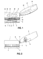
Figure 1 shows an elevational section view of a first embodiment of the electric generator of the present invention. -
Figure 2 shows a partially sectioned elevational view of a second embodiment of the electric generator of the present invention. -
Figure 3 shows a plan view of the electric generator ofFigure 2 . -
Figure 4 shows an AA section view ofFigures 2 and3 . -
Figure 5 shows an exploded perspective view of the electric generator ofFigure 2 . -
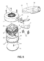
Figure 6 shows an exploded perspective view of a third embodiment of the electric generator of the present invention. -
Figure 7 shows a section view of a fourth embodiment of the invention of a generator cooled with a liquid. -
Figure 8 shows a perspective view ofFigure 7 . -
Figure 9 shows a plan view of the example ofFigures 7 and8 in which the generator is seen open. -
Figure 10 shows a section view of a fifth embodiment of the invention of a generator cooled with a liquid. -
Figure 11 shows a perspective view of the example ofFigure 9 . -
Figures 12a and 12b show a plan view and a section of the heating plate used in the embodiment ofFigures 10 and11 . - In view of the drawings, different preferred embodiments of electric generators of the present invention are described below, said electric generators comprising a circular heating plate (7) and cooling means (10, 26) between which at least one thermoelectric plate (15) is arranged, and if there is more than one heating plate, such heating plates are arranged in series, where the electric current generated between the heating plate (7) and the cooling means (10, 26) when the heating plate (7) is at a temperature greater than that of the cooling means (10, 26) due to the contact with a heat source is collected, a potential difference being established as a result.
- In a first embodiment, the circular heating plate (7) has a perimetral wall (16) and a central projection (20) between which a hollow is defined where there are arranged insulating means (8), which are a paper disc or a fireproof plate made of ceramic fiber that withstands temperatures up to 1500°C. In this embodiment, the generator has four thermoelectric plates (15) arranged in series.
- The insulating means (8) insulate the unneeded heat of the heating plate (7) to prevent it from overheating an upper plate (21) forming the base of a container (22) where the cooling means are arranged, in this embodiment, the cooling means are water (26) arranged inside said container (22). Likewise, the insulating means (8) electrically and thermally insulate the cables of the thermoelectric plates (15). A heat-conducting silicone or resin layer (23) is arranged on said thermoelectric plates (15).
- A deformable ring or gasket (24) made of fireproof material is arranged on the perimetral wall (16) of the heating plate (7) such that the height of the heating plate (7) plus the height of the deformable ring (24) in the area of the perimetral wall (16) is the same as the height of the heating plate (7) plus the height of the thermoelectric plates (15) plus the height of the heat-conducting silicone or resin layer (23) in the area of the central projection (20).
- A baffle plate (9) which prevents the circular heating plate (7) from melting in the event that the heat source is at a high temperature is arranged below the heating plate (7). The electric generator further comprises temperature control means comprising bimetallic rods (17) attached at one of their ends to the baffle plate (9) and at the other end to the circular heating plate (7), insulating the circular heating plate (7) from a heat energy source when a predetermined temperature, in this
case 100°C, is exceeded. - The container (22) comprises a handle (27) with a hole (28) for the passage of the connection cables of the thermoelectric plates (15), at the end of which handle an electric potential output terminal (29) of the 12-V lighter-type is coupled.
- In a second embodiment shown in
Figures 2 to 5 , the circular heating plate (7) has a perimetral wall (16) defining a hollow where there are arranged insulating means (8), which are a paper disc or a fireproof plate made of ceramic fiber that withstands temperatures up to 1500°C, and the thermoelectric plates (15), which are arranged in a central hole (25) of the insulating means (8). The insulating means (8) are thus radially arranged between the thermoelectric plates (15) and the perimetral wall (16). - The insulating means (8) insulate the unneeded heat of the heating plate (7) to prevent it from overheating the elements which are arranged thereon and which will be described below, and they electrically and thermally insulate the cables of the thermoelectric plates (15). A heat-conducting silicone or resin layer (not shown in
-
Figures 2 to 5 ) is arranged on the thermoelectric plates (15). - An aluminum sink (2) having a polished lower mirror surface and with grid fins to discharge the heat coming from the heating plate (7) is arranged on the assembly formed by the circular heating plate (7), the insulating means (8) and the thermoelectric plates (15). The cables of the thermoelectric plates (15) pass through the sink (2).
- There are arranged on the sink (2) cooling means which in this preferred embodiment are a fan (10) which is connected to the wiring of the thermoelectric plates (15) and works at the same voltage as that obtained from the potential output terminal, which is 12 V and at a current of 0.2 A, and is activated when the current generated as the generator starts heating up reaches 2.2 V. The connections of the thermoelectric plates (15) to the cables are arranged on the fins of the sink (2) (not shown) and at the sides of the fan. The electric generator comprises a digital voltmeter powered by the actual current obtained by the thermoelectric plates (15). This example may have a handle (3) for the exit of the wiring or, in contrast, it may not have a handle such that all the power generated by the generator is allocated for powering the fan, such that the device is converted into a hot air diffuser as it can be located on heat sources and be limited to distributing heat in the room where it is used.
- The circular heating layer (7) is screwed to the sink (2) through first screws (11) arranged in the holes of the heating layer (7), of the insulating means (8) and of the sink (2).
- A baffle plate (9) which prevents the circular heating plate (7) from melting in the event that the heat source is at a high temperature is arranged below the circular heating plate (7).
- The electric generator further comprises temperature control means comprising a buzzer (not shown) connected to a thermostat (not shown) which emits an acoustic signal when said heating plate (7) reaches a predetermined temperature, or bimetallic rods (not shown in
Figures 2 to 5 ) attached at one of their ends to the baffle plate (9) and at the other end to the circular heating plate (7), insulating the circular heating plate (7) from a heat energy source when a predetermined temperature, in thiscase 100°C, is exceeded. - A lid (1) made of sheet metal or aluminum with holes having dimensions suitable for the fan to take in air and at the same time for preventing the accidental entry of foreign objects, particularly human fingers, is arranged on the sink (2) and covering the fan. The lid (1) is attached to the fan and to the sink (2) through second screws (12) and spacers (6).
- A light bulb socket (not shown) for lighting a light bulb when current starts to be generated, a power, pilot or positional LED, or any presence-indicating light source, is arranged on the center of the lid (1). The generator also has a switch in the event that this source is to be cut off and a larger load is to be obtained from the 12-V socket.
- The electric current is extracted from the thermoelectric plates (15) by means of the conductor cables which are connected to an electric potential output terminal (29) of the 12-V lighter-type (not shown), arranged in a handle attached to the lid (1). The handle comprises a main body (3), a structure (5) that attaches the handle to the lid (1) and a closure cover (4) fixing the structure (5) that attaches the handle to the lid (1) to the main body (3). This fixing is carried out by means of third screws (13). The structure (5) that attaches the handle to the lid (1) is attached to said lid (1) by means of fourth screws (14).
- The main body (3) of the handle comprises a hole (18) for the passage of the connection cables which emerge through a perimetral hole (19) of the lid (1) and are connected to a potential output terminal (29) of the 12-V lighter-type.
- The socket for a user is therefore located away from the heating plate (7), which allows the connection of 12-V extensions, voltage dividers for USB and 220-V power inverters.
- The electric generator of this second preferred embodiment provides 20 V and 2 A when there is no load and 12-V and 1.6 A when loaded, which allows lighting a low consumption 15-W neon light bulb (equal to 75 W of incandescence) or a 10-W light bulb and at the same time as lighting the light bulb, charging a battery charger, a mobile telephone charger, or other electronic devices such as ipods or ipads. At the same time, it can light up to 5 3-W LED light bulbs (each one equal to 75 W of incandescence) or any apparatus powered through a USB port.
- In a third embodiment shown in
Figure 6 , the circular heating plate (7) has a perimetral wall (16) defining a hollow with the central projection (20) in which the thermoelectric plate (15) is located, in which hollow there are arranged insulating means (8), which are a paper disc or a fireproof plate made of ceramic fiber that withstands temperatures up to 1500°C, and the thermoelectric plates (15), which are arranged in a central hole (25) of the insulating means (8). The insulating means (8) are thus radially arranged between the thermoelectric plates (15) and the perimetral wall (16). A conductor plate (30) acting as cooling means is arranged on the insulating means (8) and the thermoelectric plates (15). - The cables of the thermoelectric plates (15) can be connected to an electric potential output terminal (29) of the 12-V lighter-type or voltage divider-type for USB arranged in a flexible protective fireproof sheath (31).
- In a fourth embodiment shown in
Figures 7 to 9 , the electric generator (100) comprises a circular heating plate (7) with a perimetral wall (16) on which a thermoelectric plate (15) is arranged preferably attached to the upper surface of the heating plate (7) by means of an adhesive to facilitate assembly, and air preferably acting as the insulating means (8) between the thermoelectric plate (15) and the perimetral wall (16). It is also possible to use two thermoelectric plates connected in series, for which purpose insulating and fireproof elements are used in the connection of the cables between plates (15) to prevent said wiring from contacting the material of the generator. As in the preceding cases, the insulating means can also be a ceramic plate or a suitable gas. The upper plate (21) representing the lower base of the container (22) in which the cooling means (26) of the generator (100), preferably water, are introduced, is located on the thermoelectric plate (15) and supported on the perimetral wall (16). A fireproof and deformable ring or gasket (24) is arranged between the upper plate (21) and the perimetral wall (16). The container (22) is secured to the heating plate (7) by means of screws (55) that go through the heating plate (7) to the upper plate (21), which is the lower base of the container (22). Said container comprises at its upper base, opposite the upper plate (21) or lower base of the container (22), a grip (41) which allows transporting the generator (100). It also comprises a lid (40) which is arranged on said upper base of the container (22). The heating plate (7) is attached to the upper plate (21) preferably by means of screws (55). - After the device is assembled, said thermoelectric plate or plates (15) are in direct contact with the upper surface of the heating plate (7) and with the lower surface of the upper plate (21), pressed between them, said contact surfaces of the heating plate (7) and of the upper plate (21) being polished mirror surfaces.
- The wiring or cables coming out of the thermoelectric plate (15) run between the heating plate (7) and the upper plate (21). Said upper plate (21) has a threaded hole (46) connecting with a flexible, insulating and leak-tight conduit or sheath (43) which is screwed into the threaded hole (46) of the upper plate (21). The coupling between the conduit (43) and the threaded hole (46) of the plate is leak-tight. The wiring of the thermoelectric plate (15) comes out from inside the generator (100) through the inside of the conduit (43), being connected to an electric potential output terminal (29) of the 12-V lighter-type or voltage divider-type for USB. When the generator (100) is not in use, it is possible to store the conduit or sheath (43) inside the container (22) and close same with the lid (40), which is preferably screwed onto the container (22).
- Therefore, the generated electricity is extracted from the generator (100) going through the cooling means (26), preventing the wiring from being exposed to the heat source on which the generator (100) is arranged and thus preventing said wiring from being overheated. As mentioned, said sheath (43) is leak-tight and fireproof and comprises sealing gaskets at the ends.
- All the components of the generator (100) of this embodiment are preferably manufactured in aluminum, said parts being anodized for the purpose of protecting the material from oxidation. The thickness of the upper plate (21), which is the cold plate of the device, preferably has a thickness between 7 and 10 mm, and the heating plate (7) preferably has a thickness between 8 and 12 mm. These thicknesses, along with the material, allows using air instead of other elements as the insulating means (8), since a plate having such thickness allows better and greater heat dissipation, preventing the temperature of the thermoelectric plate from exceeding the limit use temperature of 400°C.
- Compared with other constructions, the generator object of this example has the advantages of weighing less, about 535 grams, since components such as a sink or fan are not included, of being more compact due to its smaller size, more robust due to the non-existence of moving components preventing repairs, and all the power generated is allocated for being used by external elements and not for powering the components themselves, such as the fan.
- Once the different components are assembled, a generator (100) as described in this last embodiment preferably has a height of 48 mm and a diameter of 100 mm. The lid (40) has a height of 8 mm. The thermoelectric plates (15) that are used have dimensions of 40 mm x 40 mm.
- In a fifth and last embodiment of the present invention,
Figures 10 to 12 , as in the preceding example, the generator (200) comprises a circular heating plate (7) with a perimetral wall (16), said plate (7) having three projections (20) on its upper surface to increase the distance between the thermoelectric plates (15) with respect to the heat source since a thermoelectric plate (15) preferably attached with an adhesive to facilitate assembly is arranged on each projection (20), the air acting as insulating means (8) between the thermoelectric plates (15) and the perimetral wall (16). As in the preceding case, the insulating means (8) can be a ceramic plate. Said thermoelectric plates (15) are connected in series and their connection points are covered by an insulating and fireproof material which prevents the cables from contacting the material of the generator (200). - The upper plate (45) representing the lower base of the container in which the cooling means (26) of the generator (200), preferably water, are introduced, is located on the thermoelectric plates (15) and supported on the perimetral wall (16). A fireproof and deformable ring or gasket (24) is arranged between said perimetral wall (16) and the upper plate (45). Said container can be formed as a single part or, as shown in the drawings, it can be formed by a cylindrical wall (44) screwed to the upper plate (45) representing the lower base of the container. A baffle plate (9) made of stainless steel which prevents the circular heating plate (7) from melting in the event that the heat source is at a temperature can be arranged below the heating plate (7). Although this baffle plate (9) is not strictly necessary and will depend on the conditions of use of the generator (200), it allows prolonging the service life of the heating plate (7) manufactured in aluminum which deteriorates with heat and oxygen.
- The heating plate (7) is attached to the upper plate (45) preferably by means of screws (54), and if the generator (200) has a baffle plate (9), this is attached to the heating plate (7) also preferably by means of screws (53).
- As in the preceding examples and as detailed in the preceding example, the thermoelectric plates (15) are in direct contact with and pressed between the upper surface of the heating plate (7) and the lower surface of the upper plate (45), these two surfaces being polished mirror surfaces.
- The container (45, 44) is secured to the heating plate (7) by means of screws (54) that go through the heating plate (7) to the upper plate (45) representing the base of the container. The baffle plate (9) is secured to the heating plate (7) by means of screws (54).
- Said container comprises in its upper base, opposite the upper plate (45) or lower base of the container, a grip (41) which allows transporting the generator (100). It also comprises two holes (51, 52) close to said upper base, although there could be only one hole. Said holes (51, 52) allow connecting tubings for extracting heated water, preventing the water from evaporating. By means of said recirculation, said hot water is used such that, for example, it can be recirculated to the container after passing through a radiator, in which case the wall of the container would have two holes (51, 52), one for the exit and another for the entry of water, or the hot water is only extracted for use in washing, for example. In this last case, only one hole would be necessary, so the wall of the container (44) can have a single hole or one of the two holes can be covered if it has two holes.
- The wiring or cables coming out of the thermoelectric plates (15) run between the heating plate (7) and the upper plate (44). Said upper plate (21) has a threaded hole (47) connecting with a flexible conduit (42) which is screwed into the threaded hole (47) of the upper plate (44). Said flexible conduit (42) internally conducts the wiring coming from the thermoelectric plates (15), said wiring preferably being introduced in a leak-tight and fireproof sheath. Sealing gaskets are arranged at the ends of the conduit. The coupling between the conduit (42) and the threaded hole (47) of the plate (44) is leak-tight. The wiring of the thermoelectric plates (15) arranged in series comes out from inside the generator (200) through the inside of the conduit (42), being connected to an electric potential output terminal (29) of the 12-V lighter-type or voltage divider-type for USB.
- Therefore, the generated electricity is extracted from the generator (200) going through the cooling means (26), preventing the wiring from being exposed to the heat source on which the generator (200) is arranged and thus preventing said wiring from being overheated.
- As in the preceding example, all the components of the generator (200) of this embodiment are preferably manufactured in aluminum, except for the baffle plate (9) which is made of stainless steel, said parts being anodized for the purpose of protecting the material from oxidation. The thickness of the upper plate (21), which is the cold plate of the device, preferably has a thickness between 7 and 10 mm and the heating plate (7), or hot plate, preferably has a thickness between 8 and 12 mm. These thicknesses, along with the material, preferably allows using air instead of other elements as the insulating means (8), since a plate having such thickness allows better and greater heat dissipation, preventing the temperature of the thermoelectric plate from exceeding the limit use temperature of 400°C. It is also possible to use a ceramic plate as insulating means (8) if the conditions require it.
- By means of the generator (200) of this last embodiment, it is possible to use the heated water of the cooling means (26) as well as to obtain electric power.
- Compared to those described above, this generator (200) has the advantages of allowing greater autonomy, greater robustness since it lacks moving components, preventing repairs, recycling cooling water, using the water for heating and allocating all the generated power for use.
- Once the different components are assembled, a generator (200) such as the one described in this last embodiment preferably has a height of 160 mm and a diameter of 130 mm. The thermoelectric plates (15) that are used have dimensions of 40 mm x 40 mm.
- Compared with those described above, the last two generators (100, 200) generally have the advantage of the non-existence of moving components, which facilitates their maintenance and prolongs their life since possible assembly and use faults are reduced since the generators object of the invention are preferably ideal for use in remote places with limited energy resources and without means for repairing the generators. Therefore, these last generators are more compact and resistant as can be deduced from the preceding explanation.
- In any case, and based on the different examples, the features thereof could be combined and applied between different generators for the purpose of carrying out specific applications depending on different needs. For example, a thermostat or temperature control device associated with a device which emits an acoustic or light signal can be arranged in any of the generators.
- It must be pointed out that in generators which use water as the cooling element, it will be necessary to ensure that the container always has a minimum water level such that the operation of the generator is assured, and the thermoelectric plates are in turn prevented from being burned or damaged. Different means can be used to ensure said water supply, for example manual means, such that someone is responsible for maintaining the water level, or autonomous means, such as arranging a receptacle with water on the generator and regulating the supply of water from said receptacle.
- Having sufficiently described the nature of the invention as well as the manner of putting it into practice, it is not considered necessary to further describe the invention so that any person skilled in the art can comprehend the scope thereof and advantages derived from it, it being stated that it could be carried out to practice within its essential features in other embodiments differing in detail from that indicated by way of example, which embodiments will also achieve the protection sought provided that the fundamental principle thereof is not altered, changed or modified.
Claims (22)
- An electric generator comprising a heating plate (7) transmitting heat to cooling means (10, 26, 30), and at least one thermoelectric plate (15) arranged between the heating plate (7) and the cooling means (10, 26, 30) where an electromotive force generating an electric current is produced when the heating plate (7), located on an external heat source, is at a temperature greater than that of the cooling means (10, 26, 30), characterized in that it further comprises insulating means (8) surrounding the at least one thermoelectric plate (15) and arranged between the heating plate (7) and the cooling means (10, 26, 30).
- The generator according to claim 1, characterized in that the thermoelectric plate (15) comprises wiring at the free end of which an electric potential output terminal (29) for the output of electric potential generated in said plate (15) is located.
- The generator according to claim 2, characterized in that the wiring of the thermoelectric plate (15) exits the generator, going through the cooling means (26) without being exposed to the external heat source.
- The generator according to claim 1, characterized in that there is arranged on the heating plate (7) an upper plate (21, 45) forming the lower base of a container (22, 44) where the cooling means (26) are arranged.
- The generator according to claims 2 and 4, characterized in that the wiring goes through the upper plate (21, 45) and the cooling means (26) without being exposed to the external heat source.
- Generator according to claim 1, characterized in that the heating plate (7) has a perimetral wall (16) defining a hollow between said wall and the thermoelectric plate (15) where the insulating means (8) are arranged.
- The generator according to claim 6, characterized in that the heating plate (7) comprises at least one central projection (20) on which the thermoelectric plate (15) is arranged.
- The generator according to claim 1, characterized in that the insulating means (8) are air surrounding the at least one thermoelectric plate.
- The generator according to claim 1, characterized in that the cooling means are water (26).
- The generator according to claim 1, characterized in that the cooling means are a conductor plate (30) arranged on the insulating means (8) and the thermoelectric plates (15).
- The generator according to claim 1, characterized in that it comprises a heat-conducting silicone or resin layer (23) arranged on the thermoelectric plate (15).
- The generator according to claim 6, characterized in that it comprises a deformable ring (24) made of fireproof material arranged on the perimetral wall (16) of the heating plate (7).
- The generator according to claims 4, 6 and 12, characterized in that the deformable ring (24), the insulating means (8) and the heat-conducting silicone or resin layer (23) are arranged between the heating plate (7) and the upper plate (21, 45).
- The generator according to claim 1, characterized in that it comprises an aluminum sink (2) having a polished lower mirror surface and with grid fins arranged on the assembly formed by the heating plate (7), the insulating means (8) and the thermoelectric plates (15) to discharge the heat coming from the heating plate (7).
- The generator according to claim 1, characterized in that the cooling means are a fan (10) connected to the wiring of the thermoelectric plates (15) which works at the same voltage as that obtained from the potential output terminal (29).
- The generator according to claim 4, characterized in that the wall of the container (44) comprises at least one hole (51, 52) for the exit or entry of the cooling means (26).
- The generator according to claim 16, characterized in that it comprises two holes (51, 52), one for the exit of the cooling means (26) and one for the entry of said cooling means (26).
- The generator according to claim 1, characterized in that it comprises a baffle plate (9) arranged below the heating plate (7).
- The generator according to claim 1, characterized in that it comprises temperature control means which emit an acoustic signal when the heating plate (7) reaches a predetermined temperature.
- The generator according to claim 2, characterized in that the potential output terminal (29) is a 12-V lighter-type terminal.
- The generator according to claim 2, characterized in that the potential output terminal (29) is a voltage divider-type terminal for USB.
- The generator according to the preceding claims, characterized in that the thickness of the heating plate (7) and the upper plate (21, 45) is between 7 and 12 mm.
Applications Claiming Priority (2)
| Application Number | Priority Date | Filing Date | Title |
|---|---|---|---|
| ES201131153U ES1076458Y (en) | 2011-11-08 | 2011-11-08 | ELECTRIC GENERATOR |
| PCT/ES2012/070772 WO2013068623A2 (en) | 2011-11-08 | 2012-11-07 | Electricity generator |
Publications (3)
| Publication Number | Publication Date |
|---|---|
| EP2782151A2 true EP2782151A2 (en) | 2014-09-24 |
| EP2782151A4 EP2782151A4 (en) | 2015-03-18 |
| EP2782151B1 EP2782151B1 (en) | 2016-03-30 |
Family
ID=45699159
Family Applications (1)
| Application Number | Title | Priority Date | Filing Date |
|---|---|---|---|
| EP12847374.1A Not-in-force EP2782151B1 (en) | 2011-11-08 | 2012-11-07 | Electricity generator |
Country Status (6)
| Country | Link |
|---|---|
| US (1) | US20140311545A1 (en) |
| EP (1) | EP2782151B1 (en) |
| CA (1) | CA2854602A1 (en) |
| ES (2) | ES1076458Y (en) |
| MX (1) | MX2014005567A (en) |
| WO (1) | WO2013068623A2 (en) |
Families Citing this family (1)
| Publication number | Priority date | Publication date | Assignee | Title |
|---|---|---|---|---|
| BR112015013097A2 (en) * | 2012-12-04 | 2017-07-11 | Mark Goldberg Allan | thermoelectric generator arrangement |
Citations (7)
| Publication number | Priority date | Publication date | Assignee | Title |
|---|---|---|---|---|
| US3082276A (en) * | 1960-08-17 | 1963-03-19 | Westinghouse Electric Corp | Thermoelectric appliance |
| WO2001080325A1 (en) * | 2000-04-13 | 2001-10-25 | Hi-Z Technology, Inc. | Combustion heat powered portable electronic device |
| JP2002136160A (en) * | 2000-10-27 | 2002-05-10 | Seiko Epson Corp | Thermoelectric generator |
| US20100083946A1 (en) * | 2008-10-07 | 2010-04-08 | Cedar Jonathan M | Portable combustion device utilizing thermoelectrical generation |
| CN201708191U (en) * | 2010-07-08 | 2011-01-12 | 江西纳米克热电电子股份有限公司 | Small-sized portable semiconductor thermoelectric generator |
| US20110284047A1 (en) * | 2010-05-20 | 2011-11-24 | Joshua Heath Johnson | Multi-use camping pot that produces power from heat |
| US20120153636A1 (en) * | 2010-12-21 | 2012-06-21 | AltEn, LLC | Passively Cooled Lightweight Thermoelectric Generator System |
Family Cites Families (6)
| Publication number | Priority date | Publication date | Assignee | Title |
|---|---|---|---|---|
| ES1061083Y (en) * | 2005-07-07 | 2006-04-16 | Friedemann Hoffmann | LIGHTING DEVICE WITH ENERGY RECOVERY |
| US9105809B2 (en) * | 2007-07-23 | 2015-08-11 | Gentherm Incorporated | Segmented thermoelectric device |
| ES2323931B1 (en) * | 2008-01-25 | 2010-03-16 | Xavier Ceron Parisi | SOLAR THERMOELECTRIC PLATE. |
| ES2388564T3 (en) * | 2009-10-20 | 2012-10-16 | Kapsch Trafficcom Ag | Vehicle appliance |
| DE102009046099A1 (en) * | 2009-10-28 | 2011-05-05 | Robert Bosch Gmbh | Method for producing a sea shelf module and corresponding sea shelf module |
| ES1073131Y (en) * | 2010-06-24 | 2011-02-08 | Inst Del Corcho La Madera Y El Carbon Vegetal Icmc | DEVICE FOR THE USE OF THERMAL ENERGY RELEASED IN COOKING BOILERS, FOR THE GENERATION OF ELECTRICAL ENERGY |
-
2011
- 2011-11-08 ES ES201131153U patent/ES1076458Y/en not_active Expired - Fee Related
-
2012
- 2012-11-07 EP EP12847374.1A patent/EP2782151B1/en not_active Not-in-force
- 2012-11-07 WO PCT/ES2012/070772 patent/WO2013068623A2/en active Application Filing
- 2012-11-07 ES ES12847374.1T patent/ES2577407T3/en active Active
- 2012-11-07 MX MX2014005567A patent/MX2014005567A/en not_active Application Discontinuation
- 2012-11-07 CA CA2854602A patent/CA2854602A1/en not_active Abandoned
- 2012-11-07 US US14/356,822 patent/US20140311545A1/en not_active Abandoned
Patent Citations (7)
| Publication number | Priority date | Publication date | Assignee | Title |
|---|---|---|---|---|
| US3082276A (en) * | 1960-08-17 | 1963-03-19 | Westinghouse Electric Corp | Thermoelectric appliance |
| WO2001080325A1 (en) * | 2000-04-13 | 2001-10-25 | Hi-Z Technology, Inc. | Combustion heat powered portable electronic device |
| JP2002136160A (en) * | 2000-10-27 | 2002-05-10 | Seiko Epson Corp | Thermoelectric generator |
| US20100083946A1 (en) * | 2008-10-07 | 2010-04-08 | Cedar Jonathan M | Portable combustion device utilizing thermoelectrical generation |
| US20110284047A1 (en) * | 2010-05-20 | 2011-11-24 | Joshua Heath Johnson | Multi-use camping pot that produces power from heat |
| CN201708191U (en) * | 2010-07-08 | 2011-01-12 | 江西纳米克热电电子股份有限公司 | Small-sized portable semiconductor thermoelectric generator |
| US20120153636A1 (en) * | 2010-12-21 | 2012-06-21 | AltEn, LLC | Passively Cooled Lightweight Thermoelectric Generator System |
Also Published As
| Publication number | Publication date |
|---|---|
| ES2577407T3 (en) | 2016-07-14 |
| EP2782151A4 (en) | 2015-03-18 |
| MX2014005567A (en) | 2014-10-14 |
| ES1076458Y (en) | 2012-06-08 |
| ES1076458U (en) | 2012-03-12 |
| EP2782151B1 (en) | 2016-03-30 |
| US20140311545A1 (en) | 2014-10-23 |
| WO2013068623A2 (en) | 2013-05-16 |
| WO2013068623A3 (en) | 2013-08-01 |
| CA2854602A1 (en) | 2013-05-16 |
Similar Documents
| Publication | Publication Date | Title |
|---|---|---|
| JP5237788B2 (en) | Improvement of cooking stove | |
| US9811985B2 (en) | Power outage safety light bulb | |
| CN104467069B (en) | Battery charging device and system comprising a battery charging device | |
| US9214657B2 (en) | Power storage device and power storage system | |
| WO2010133814A1 (en) | Generating electrical power from heating system using thermoelectric generator | |
| KR102017715B1 (en) | Portable heat power generating apparatus | |
| JP2015171308A (en) | temperature difference power generator | |
| JP6890270B2 (en) | Emergency lighting equipment and lighting equipment | |
| EP2782151B1 (en) | Electricity generator | |
| GB2454714A (en) | Thermoelectric low voltage light | |
| US8618406B1 (en) | Thermoelectric power generation method and apparatus | |
| JP2008251359A (en) | Lighting device for use at low temperature | |
| JP7373757B2 (en) | lighting equipment | |
| CA2830236A1 (en) | Device for converting heat into electrical power | |
| KR20000056018A (en) | Portable generator using thermoelectric semiconductor and its controlling method in outdoor life | |
| KR101529219B1 (en) | Power generator using the lost heat of the gas burner | |
| KR101730541B1 (en) | A power supply device with a heat dissipation function | |
| TW201314115A (en) | LED lamp | |
| RU101149U1 (en) | EXPLOSION-FREE LED LIGHT | |
| KR200415926Y1 (en) | With generator for heater | |
| RU78391U1 (en) | LIGHTING DEVICE "SV LIGHT" | |
| KR20190012385A (en) | Electric power generation type cooking vessel stand for heating cooker | |
| US20230268809A1 (en) | Power Box Generator | |
| WO2015144944A1 (en) | Portable electrical power supply system | |
| ITRM20100034A1 (en) | ELECTRIC GENERATOR POWERED BY HEAT SOURCES |
Legal Events
| Date | Code | Title | Description |
|---|---|---|---|
| PUAI | Public reference made under article 153(3) epc to a published international application that has entered the european phase |
Free format text: ORIGINAL CODE: 0009012 |
|
| 17P | Request for examination filed |
Effective date: 20140523 |
|
| AK | Designated contracting states |
Kind code of ref document: A2 Designated state(s): AL AT BE BG CH CY CZ DE DK EE ES FI FR GB GR HR HU IE IS IT LI LT LU LV MC MK MT NL NO PL PT RO RS SE SI SK SM TR |
|
| DAX | Request for extension of the european patent (deleted) | ||
| A4 | Supplementary search report drawn up and despatched |
Effective date: 20150218 |
|
| RIC1 | Information provided on ipc code assigned before grant |
Ipc: H01L 35/00 20060101AFI20150212BHEP Ipc: H01L 35/32 20060101ALI20150212BHEP Ipc: H01L 35/30 20060101ALI20150212BHEP |
|
| GRAP | Despatch of communication of intention to grant a patent |
Free format text: ORIGINAL CODE: EPIDOSNIGR1 |
|
| RIC1 | Information provided on ipc code assigned before grant |
Ipc: H01L 35/32 20060101ALI20151110BHEP Ipc: H01L 35/00 20060101AFI20151110BHEP Ipc: H01L 35/30 20060101ALI20151110BHEP |
|
| INTG | Intention to grant announced |
Effective date: 20151207 |
|
| GRAS | Grant fee paid |
Free format text: ORIGINAL CODE: EPIDOSNIGR3 |
|
| GRAA | (expected) grant |
Free format text: ORIGINAL CODE: 0009210 |
|
| AK | Designated contracting states |
Kind code of ref document: B1 Designated state(s): AL AT BE BG CH CY CZ DE DK EE ES FI FR GB GR HR HU IE IS IT LI LT LU LV MC MK MT NL NO PL PT RO RS SE SI SK SM TR |
|
| REG | Reference to a national code |
Ref country code: GB Ref legal event code: FG4D |
|
| REG | Reference to a national code |
Ref country code: CH Ref legal event code: EP |
|
| REG | Reference to a national code |
Ref country code: AT Ref legal event code: REF Ref document number: 786227 Country of ref document: AT Kind code of ref document: T Effective date: 20160415 |
|
| REG | Reference to a national code |
Ref country code: IE Ref legal event code: FG4D |
|
| REG | Reference to a national code |
Ref country code: DE Ref legal event code: R096 Ref document number: 602012016440 Country of ref document: DE |
|
| REG | Reference to a national code |
Ref country code: ES Ref legal event code: FG2A Ref document number: 2577407 Country of ref document: ES Kind code of ref document: T3 Effective date: 20160714 |
|
| REG | Reference to a national code |
Ref country code: LT Ref legal event code: MG4D |
|
| PG25 | Lapsed in a contracting state [announced via postgrant information from national office to epo] |
Ref country code: HR Free format text: LAPSE BECAUSE OF FAILURE TO SUBMIT A TRANSLATION OF THE DESCRIPTION OR TO PAY THE FEE WITHIN THE PRESCRIBED TIME-LIMIT Effective date: 20160330 Ref country code: NO Free format text: LAPSE BECAUSE OF FAILURE TO SUBMIT A TRANSLATION OF THE DESCRIPTION OR TO PAY THE FEE WITHIN THE PRESCRIBED TIME-LIMIT Effective date: 20160630 Ref country code: FI Free format text: LAPSE BECAUSE OF FAILURE TO SUBMIT A TRANSLATION OF THE DESCRIPTION OR TO PAY THE FEE WITHIN THE PRESCRIBED TIME-LIMIT Effective date: 20160330 Ref country code: GR Free format text: LAPSE BECAUSE OF FAILURE TO SUBMIT A TRANSLATION OF THE DESCRIPTION OR TO PAY THE FEE WITHIN THE PRESCRIBED TIME-LIMIT Effective date: 20160701 |
|
| REG | Reference to a national code |
Ref country code: NL Ref legal event code: MP Effective date: 20160330 |
|
| REG | Reference to a national code |
Ref country code: AT Ref legal event code: MK05 Ref document number: 786227 Country of ref document: AT Kind code of ref document: T Effective date: 20160330 |
|
| PG25 | Lapsed in a contracting state [announced via postgrant information from national office to epo] |
Ref country code: LT Free format text: LAPSE BECAUSE OF FAILURE TO SUBMIT A TRANSLATION OF THE DESCRIPTION OR TO PAY THE FEE WITHIN THE PRESCRIBED TIME-LIMIT Effective date: 20160330 Ref country code: LV Free format text: LAPSE BECAUSE OF FAILURE TO SUBMIT A TRANSLATION OF THE DESCRIPTION OR TO PAY THE FEE WITHIN THE PRESCRIBED TIME-LIMIT Effective date: 20160330 Ref country code: RS Free format text: LAPSE BECAUSE OF FAILURE TO SUBMIT A TRANSLATION OF THE DESCRIPTION OR TO PAY THE FEE WITHIN THE PRESCRIBED TIME-LIMIT Effective date: 20160330 Ref country code: SE Free format text: LAPSE BECAUSE OF FAILURE TO SUBMIT A TRANSLATION OF THE DESCRIPTION OR TO PAY THE FEE WITHIN THE PRESCRIBED TIME-LIMIT Effective date: 20160330 |
|
| PG25 | Lapsed in a contracting state [announced via postgrant information from national office to epo] |
Ref country code: NL Free format text: LAPSE BECAUSE OF FAILURE TO SUBMIT A TRANSLATION OF THE DESCRIPTION OR TO PAY THE FEE WITHIN THE PRESCRIBED TIME-LIMIT Effective date: 20160330 |
|
| PG25 | Lapsed in a contracting state [announced via postgrant information from national office to epo] |
Ref country code: EE Free format text: LAPSE BECAUSE OF FAILURE TO SUBMIT A TRANSLATION OF THE DESCRIPTION OR TO PAY THE FEE WITHIN THE PRESCRIBED TIME-LIMIT Effective date: 20160330 Ref country code: IS Free format text: LAPSE BECAUSE OF FAILURE TO SUBMIT A TRANSLATION OF THE DESCRIPTION OR TO PAY THE FEE WITHIN THE PRESCRIBED TIME-LIMIT Effective date: 20160730 Ref country code: PL Free format text: LAPSE BECAUSE OF FAILURE TO SUBMIT A TRANSLATION OF THE DESCRIPTION OR TO PAY THE FEE WITHIN THE PRESCRIBED TIME-LIMIT Effective date: 20160330 |
|
| PG25 | Lapsed in a contracting state [announced via postgrant information from national office to epo] |
Ref country code: SM Free format text: LAPSE BECAUSE OF FAILURE TO SUBMIT A TRANSLATION OF THE DESCRIPTION OR TO PAY THE FEE WITHIN THE PRESCRIBED TIME-LIMIT Effective date: 20160330 Ref country code: SK Free format text: LAPSE BECAUSE OF FAILURE TO SUBMIT A TRANSLATION OF THE DESCRIPTION OR TO PAY THE FEE WITHIN THE PRESCRIBED TIME-LIMIT Effective date: 20160330 Ref country code: PT Free format text: LAPSE BECAUSE OF FAILURE TO SUBMIT A TRANSLATION OF THE DESCRIPTION OR TO PAY THE FEE WITHIN THE PRESCRIBED TIME-LIMIT Effective date: 20160801 Ref country code: RO Free format text: LAPSE BECAUSE OF FAILURE TO SUBMIT A TRANSLATION OF THE DESCRIPTION OR TO PAY THE FEE WITHIN THE PRESCRIBED TIME-LIMIT Effective date: 20160330 Ref country code: CZ Free format text: LAPSE BECAUSE OF FAILURE TO SUBMIT A TRANSLATION OF THE DESCRIPTION OR TO PAY THE FEE WITHIN THE PRESCRIBED TIME-LIMIT Effective date: 20160330 Ref country code: AT Free format text: LAPSE BECAUSE OF FAILURE TO SUBMIT A TRANSLATION OF THE DESCRIPTION OR TO PAY THE FEE WITHIN THE PRESCRIBED TIME-LIMIT Effective date: 20160330 |
|
| PG25 | Lapsed in a contracting state [announced via postgrant information from national office to epo] |
Ref country code: IT Free format text: LAPSE BECAUSE OF FAILURE TO SUBMIT A TRANSLATION OF THE DESCRIPTION OR TO PAY THE FEE WITHIN THE PRESCRIBED TIME-LIMIT Effective date: 20160330 Ref country code: BE Free format text: LAPSE BECAUSE OF FAILURE TO SUBMIT A TRANSLATION OF THE DESCRIPTION OR TO PAY THE FEE WITHIN THE PRESCRIBED TIME-LIMIT Effective date: 20160330 |
|
| REG | Reference to a national code |
Ref country code: DE Ref legal event code: R097 Ref document number: 602012016440 Country of ref document: DE |
|
| PG25 | Lapsed in a contracting state [announced via postgrant information from national office to epo] |
Ref country code: DK Free format text: LAPSE BECAUSE OF FAILURE TO SUBMIT A TRANSLATION OF THE DESCRIPTION OR TO PAY THE FEE WITHIN THE PRESCRIBED TIME-LIMIT Effective date: 20160330 |
|
| PLBE | No opposition filed within time limit |
Free format text: ORIGINAL CODE: 0009261 |
|
| STAA | Information on the status of an ep patent application or granted ep patent |
Free format text: STATUS: NO OPPOSITION FILED WITHIN TIME LIMIT |
|
| 26N | No opposition filed |
Effective date: 20170103 |
|
| PG25 | Lapsed in a contracting state [announced via postgrant information from national office to epo] |
Ref country code: SI Free format text: LAPSE BECAUSE OF FAILURE TO SUBMIT A TRANSLATION OF THE DESCRIPTION OR TO PAY THE FEE WITHIN THE PRESCRIBED TIME-LIMIT Effective date: 20160330 |
|
| REG | Reference to a national code |
Ref country code: DE Ref legal event code: R119 Ref document number: 602012016440 Country of ref document: DE |
|
| REG | Reference to a national code |
Ref country code: CH Ref legal event code: PL |
|
| GBPC | Gb: european patent ceased through non-payment of renewal fee |
Effective date: 20161107 |
|
| PG25 | Lapsed in a contracting state [announced via postgrant information from national office to epo] |
Ref country code: CH Free format text: LAPSE BECAUSE OF NON-PAYMENT OF DUE FEES Effective date: 20161130 Ref country code: LI Free format text: LAPSE BECAUSE OF NON-PAYMENT OF DUE FEES Effective date: 20161130 |
|
| REG | Reference to a national code |
Ref country code: IE Ref legal event code: MM4A |
|
| REG | Reference to a national code |
Ref country code: FR Ref legal event code: ST Effective date: 20170731 |
|
| PG25 | Lapsed in a contracting state [announced via postgrant information from national office to epo] |
Ref country code: LU Free format text: LAPSE BECAUSE OF NON-PAYMENT OF DUE FEES Effective date: 20161130 |
|
| PG25 | Lapsed in a contracting state [announced via postgrant information from national office to epo] |
Ref country code: FR Free format text: LAPSE BECAUSE OF NON-PAYMENT OF DUE FEES Effective date: 20161130 |
|
| PG25 | Lapsed in a contracting state [announced via postgrant information from national office to epo] |
Ref country code: IE Free format text: LAPSE BECAUSE OF NON-PAYMENT OF DUE FEES Effective date: 20161107 Ref country code: GB Free format text: LAPSE BECAUSE OF NON-PAYMENT OF DUE FEES Effective date: 20161107 Ref country code: DE Free format text: LAPSE BECAUSE OF NON-PAYMENT OF DUE FEES Effective date: 20170601 |
|
| PGFP | Annual fee paid to national office [announced via postgrant information from national office to epo] |
Ref country code: ES Payment date: 20171201 Year of fee payment: 6 |
|
| PG25 | Lapsed in a contracting state [announced via postgrant information from national office to epo] |
Ref country code: HU Free format text: LAPSE BECAUSE OF FAILURE TO SUBMIT A TRANSLATION OF THE DESCRIPTION OR TO PAY THE FEE WITHIN THE PRESCRIBED TIME-LIMIT; INVALID AB INITIO Effective date: 20121107 |
|
| PG25 | Lapsed in a contracting state [announced via postgrant information from national office to epo] |
Ref country code: CY Free format text: LAPSE BECAUSE OF FAILURE TO SUBMIT A TRANSLATION OF THE DESCRIPTION OR TO PAY THE FEE WITHIN THE PRESCRIBED TIME-LIMIT Effective date: 20160330 Ref country code: MC Free format text: LAPSE BECAUSE OF FAILURE TO SUBMIT A TRANSLATION OF THE DESCRIPTION OR TO PAY THE FEE WITHIN THE PRESCRIBED TIME-LIMIT Effective date: 20160330 Ref country code: MK Free format text: LAPSE BECAUSE OF FAILURE TO SUBMIT A TRANSLATION OF THE DESCRIPTION OR TO PAY THE FEE WITHIN THE PRESCRIBED TIME-LIMIT Effective date: 20160330 |
|
| PG25 | Lapsed in a contracting state [announced via postgrant information from national office to epo] |
Ref country code: BG Free format text: LAPSE BECAUSE OF FAILURE TO SUBMIT A TRANSLATION OF THE DESCRIPTION OR TO PAY THE FEE WITHIN THE PRESCRIBED TIME-LIMIT Effective date: 20160330 |
|
| PG25 | Lapsed in a contracting state [announced via postgrant information from national office to epo] |
Ref country code: MT Free format text: LAPSE BECAUSE OF NON-PAYMENT OF DUE FEES Effective date: 20161107 |
|
| PG25 | Lapsed in a contracting state [announced via postgrant information from national office to epo] |
Ref country code: AL Free format text: LAPSE BECAUSE OF FAILURE TO SUBMIT A TRANSLATION OF THE DESCRIPTION OR TO PAY THE FEE WITHIN THE PRESCRIBED TIME-LIMIT Effective date: 20160330 Ref country code: TR Free format text: LAPSE BECAUSE OF FAILURE TO SUBMIT A TRANSLATION OF THE DESCRIPTION OR TO PAY THE FEE WITHIN THE PRESCRIBED TIME-LIMIT Effective date: 20160330 |
|
| REG | Reference to a national code |
Ref country code: ES Ref legal event code: FD2A Effective date: 20200102 |
|
| PG25 | Lapsed in a contracting state [announced via postgrant information from national office to epo] |
Ref country code: ES Free format text: LAPSE BECAUSE OF NON-PAYMENT OF DUE FEES Effective date: 20181108 |