EP2782083A1 - Driving assistance device - Google Patents
Driving assistance device Download PDFInfo
- Publication number
- EP2782083A1 EP2782083A1 EP11875966.1A EP11875966A EP2782083A1 EP 2782083 A1 EP2782083 A1 EP 2782083A1 EP 11875966 A EP11875966 A EP 11875966A EP 2782083 A1 EP2782083 A1 EP 2782083A1
- Authority
- EP
- European Patent Office
- Prior art keywords
- vehicle
- target
- information
- stopping position
- stopping
- Prior art date
- Legal status (The legal status is an assumption and is not a legal conclusion. Google has not performed a legal analysis and makes no representation as to the accuracy of the status listed.)
- Granted
Links
- 230000001133 acceleration Effects 0.000 claims description 13
- 238000004364 calculation method Methods 0.000 description 83
- 238000012545 processing Methods 0.000 description 26
- 230000001172 regenerating effect Effects 0.000 description 23
- 230000005540 biological transmission Effects 0.000 description 19
- 238000001514 detection method Methods 0.000 description 19
- 238000004891 communication Methods 0.000 description 16
- 239000000446 fuel Substances 0.000 description 15
- 230000006872 improvement Effects 0.000 description 12
- 238000006243 chemical reaction Methods 0.000 description 10
- 238000011156 evaluation Methods 0.000 description 9
- 230000006870 function Effects 0.000 description 9
- 230000008929 regeneration Effects 0.000 description 9
- 238000011069 regeneration method Methods 0.000 description 9
- 238000012937 correction Methods 0.000 description 7
- 230000000694 effects Effects 0.000 description 7
- 238000000034 method Methods 0.000 description 7
- 238000012821 model calculation Methods 0.000 description 7
- 238000010586 diagram Methods 0.000 description 6
- 230000004044 response Effects 0.000 description 6
- 230000000007 visual effect Effects 0.000 description 6
- 230000006399 behavior Effects 0.000 description 5
- 238000010248 power generation Methods 0.000 description 4
- 230000001953 sensory effect Effects 0.000 description 4
- 230000002349 favourable effect Effects 0.000 description 3
- 238000002485 combustion reaction Methods 0.000 description 2
- 239000000470 constituent Substances 0.000 description 2
- 230000007423 decrease Effects 0.000 description 2
- 239000003915 liquefied petroleum gas Substances 0.000 description 2
- 208000031427 Foetal heart rate deceleration Diseases 0.000 description 1
- 238000013459 approach Methods 0.000 description 1
- 230000008859 change Effects 0.000 description 1
- 230000007812 deficiency Effects 0.000 description 1
- 238000007599 discharging Methods 0.000 description 1
- 230000009977 dual effect Effects 0.000 description 1
- 239000003502 gasoline Substances 0.000 description 1
- 238000005286 illumination Methods 0.000 description 1
- 238000002347 injection Methods 0.000 description 1
- 239000007924 injection Substances 0.000 description 1
- 239000004973 liquid crystal related substance Substances 0.000 description 1
- 238000005259 measurement Methods 0.000 description 1
- 230000007246 mechanism Effects 0.000 description 1
- 238000012986 modification Methods 0.000 description 1
- 230000004048 modification Effects 0.000 description 1
- 230000003287 optical effect Effects 0.000 description 1
- 230000002093 peripheral effect Effects 0.000 description 1
- 230000009467 reduction Effects 0.000 description 1
- 230000003068 static effect Effects 0.000 description 1
Images


Classifications
-
- G—PHYSICS
- G08—SIGNALLING
- G08G—TRAFFIC CONTROL SYSTEMS
- G08G1/00—Traffic control systems for road vehicles
- G08G1/16—Anti-collision systems
- G08G1/166—Anti-collision systems for active traffic, e.g. moving vehicles, pedestrians, bikes
-
- B—PERFORMING OPERATIONS; TRANSPORTING
- B60—VEHICLES IN GENERAL
- B60W—CONJOINT CONTROL OF VEHICLE SUB-UNITS OF DIFFERENT TYPE OR DIFFERENT FUNCTION; CONTROL SYSTEMS SPECIALLY ADAPTED FOR HYBRID VEHICLES; ROAD VEHICLE DRIVE CONTROL SYSTEMS FOR PURPOSES NOT RELATED TO THE CONTROL OF A PARTICULAR SUB-UNIT
- B60W30/00—Purposes of road vehicle drive control systems not related to the control of a particular sub-unit, e.g. of systems using conjoint control of vehicle sub-units, or advanced driver assistance systems for ensuring comfort, stability and safety or drive control systems for propelling or retarding the vehicle
- B60W30/18—Propelling the vehicle
- B60W30/18009—Propelling the vehicle related to particular drive situations
- B60W30/181—Preparing for stopping
-
- B—PERFORMING OPERATIONS; TRANSPORTING
- B60—VEHICLES IN GENERAL
- B60W—CONJOINT CONTROL OF VEHICLE SUB-UNITS OF DIFFERENT TYPE OR DIFFERENT FUNCTION; CONTROL SYSTEMS SPECIALLY ADAPTED FOR HYBRID VEHICLES; ROAD VEHICLE DRIVE CONTROL SYSTEMS FOR PURPOSES NOT RELATED TO THE CONTROL OF A PARTICULAR SUB-UNIT
- B60W30/00—Purposes of road vehicle drive control systems not related to the control of a particular sub-unit, e.g. of systems using conjoint control of vehicle sub-units, or advanced driver assistance systems for ensuring comfort, stability and safety or drive control systems for propelling or retarding the vehicle
- B60W30/18—Propelling the vehicle
- B60W30/18009—Propelling the vehicle related to particular drive situations
- B60W30/18109—Braking
-
- B—PERFORMING OPERATIONS; TRANSPORTING
- B60—VEHICLES IN GENERAL
- B60W—CONJOINT CONTROL OF VEHICLE SUB-UNITS OF DIFFERENT TYPE OR DIFFERENT FUNCTION; CONTROL SYSTEMS SPECIALLY ADAPTED FOR HYBRID VEHICLES; ROAD VEHICLE DRIVE CONTROL SYSTEMS FOR PURPOSES NOT RELATED TO THE CONTROL OF A PARTICULAR SUB-UNIT
- B60W50/00—Details of control systems for road vehicle drive control not related to the control of a particular sub-unit, e.g. process diagnostic or vehicle driver interfaces
- B60W50/0098—Details of control systems ensuring comfort, safety or stability not otherwise provided for
-
- G—PHYSICS
- G08—SIGNALLING
- G08G—TRAFFIC CONTROL SYSTEMS
- G08G1/00—Traffic control systems for road vehicles
- G08G1/09—Arrangements for giving variable traffic instructions
- G08G1/0962—Arrangements for giving variable traffic instructions having an indicator mounted inside the vehicle, e.g. giving voice messages
- G08G1/0967—Systems involving transmission of highway information, e.g. weather, speed limits
- G08G1/096708—Systems involving transmission of highway information, e.g. weather, speed limits where the received information might be used to generate an automatic action on the vehicle control
- G08G1/096725—Systems involving transmission of highway information, e.g. weather, speed limits where the received information might be used to generate an automatic action on the vehicle control where the received information generates an automatic action on the vehicle control
-
- B—PERFORMING OPERATIONS; TRANSPORTING
- B60—VEHICLES IN GENERAL
- B60W—CONJOINT CONTROL OF VEHICLE SUB-UNITS OF DIFFERENT TYPE OR DIFFERENT FUNCTION; CONTROL SYSTEMS SPECIALLY ADAPTED FOR HYBRID VEHICLES; ROAD VEHICLE DRIVE CONTROL SYSTEMS FOR PURPOSES NOT RELATED TO THE CONTROL OF A PARTICULAR SUB-UNIT
- B60W50/00—Details of control systems for road vehicle drive control not related to the control of a particular sub-unit, e.g. process diagnostic or vehicle driver interfaces
- B60W2050/0062—Adapting control system settings
- B60W2050/0075—Automatic parameter input, automatic initialising or calibrating means
-
- B—PERFORMING OPERATIONS; TRANSPORTING
- B60—VEHICLES IN GENERAL
- B60W—CONJOINT CONTROL OF VEHICLE SUB-UNITS OF DIFFERENT TYPE OR DIFFERENT FUNCTION; CONTROL SYSTEMS SPECIALLY ADAPTED FOR HYBRID VEHICLES; ROAD VEHICLE DRIVE CONTROL SYSTEMS FOR PURPOSES NOT RELATED TO THE CONTROL OF A PARTICULAR SUB-UNIT
- B60W2556/00—Input parameters relating to data
- B60W2556/10—Historical data
Definitions
- the invention relates to a driving assistance apparatus.
- Patent Document 1 describes an apparatus that accumulates detection results from vehicle speed and position sensors and determines a condition of an intersection as this type of conventional driving assistance apparatus. Further, Patent Document 1 describes extracting a plurality of locations at which the vehicle speed is at a minimum within a predetermined range of the intersection, and setting an average position of the extracted positions as a target stopping position at which to stop temporarily. Patent Document 2 discloses an apparatus that notifies a driver of a point at which to start decelerating when it is necessary to stop at a traffic light on the basis of a time required to reach the traffic light and a time remaining until a color of the traffic light changes.
- the apparatus described in Patent Document 2 can detect a location of a temporary stop by setting a target stopping position on the basis of the accumulated detection results from the vehicle speed and position sensors, there remains room for improvement in terms of providing more appropriate driving assistance, for example. Further, although the apparatus described in Patent Document 2 provides assistance to prompt early deceleration by notifying the driver of the point at which to start decelerating when it is necessary to stop at a traffic light, there remains room for improvement in terms of providing more appropriate driving assistance, for example.
- the invention has been designed in consideration of the circumstances described above, and an object thereof is to provide a driving assistance apparatus that can provide driving assistance appropriately.
- a driving assistance apparatus assists driving of a vehicle, and includes: an assistance control apparatus that accumulates vehicle stopping position information, which is information indicating an actual stopping position in which the vehicle stops in relation to a reference stopping position, calculates an estimated variation distance between the actual stopping position and the reference stopping position on the basis of the accumulated vehicle stopping position information, and creates a target vehicle travel condition in which a timing at which stopping assistance is started is varied on the basis of the estimated variation distance; and an assistance apparatus that is capable of outputting driving assistance information to assist driving of the vehicle on the basis of a target travel condition quantity calculated by the assistance control apparatus.
- vehicle stopping position information which is information indicating an actual stopping position in which the vehicle stops in relation to a reference stopping position
- calculates an estimated variation distance between the actual stopping position and the reference stopping position on the basis of the accumulated vehicle stopping position information calculates an estimated variation distance between the actual stopping position and the reference stopping position on the basis of the accumulated vehicle stopping position information, and creates a target vehicle travel condition in which a timing at which stopping assistance is started is varied on the
- the assistance control apparatus preferably varies the timing at which the stopping assistance is started by determining a target stopping position on the basis of a difference between the estimated variation distance and the reference stopping position, and creating the target vehicle travel condition on the basis of the target stopping position.
- the assistance control apparatus preferably varies the timing at which the stopping assistance is started by correcting a target vehicle speed at the start of a brake operation on the basis of the estimated variation distance, and creating the target vehicle travel condition on the basis of the corrected target vehicle speed at the start of the brake operation.
- the estimated variation distance is preferably a distance from a position of an average value of the actual stopping positions to an actual stopping position furthest from the reference stopping position.
- the estimated variation distance is preferably a distance from a position of a median value of the actual stopping positions to a location furthest from the reference stopping position.
- the assistance control apparatus preferably sets the target stopping position in a position shifted from the reference stopping position to a near side by the estimated variation distance.
- the driving assistance apparatus preferably further includes preceding vehicle detecting means for detecting a preceding vehicle traveling in front of the vehicle in an advancement direction of the vehicle, and when the preceding vehicle detecting means detects a preceding vehicle, the assistance control apparatus preferably advances the timing at which the stopping assistance is started.
- the assistance control apparatus preferably shifts the target stopping position to the near side with respect to the reference stopping position.
- the assistance control apparatus preferably classifies the information indicating the actual stopping positions into set time patterns, calculates the estimated variation distance for each of the patterns, and creates the target vehicle travel condition on the basis of the estimated variation distance of the time pattern in which a creation time of the target vehicle travel condition is classified.
- the assistance apparatus preferably performs assistance to prompt a recommended driving operation by outputting the driving assistance information.
- the driving assistance information preferably includes information instructing cancelation of an acceleration request operation and a braking request operation.
- the driving assistance information preferably includes information instructing starting of the braking request operation.
- the driving assistance apparatus is capable of providing driving assistance appropriately.
- FIG. 1 is a schematic view showing a configuration of a vehicle control system according to a first embodiment
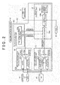
- FIG. 2 is a schematic block diagram showing an example of a configuration of an ECU according to the first embodiment
- FIG. 3 is a schematic block diagram showing an example of a configuration of a target calculation unit.
- a driving assistance apparatus 1 As shown in FIG. 1 , a driving assistance apparatus 1 according to this embodiment is applied to a vehicle control system 3 installed in a vehicle 2.
- the driving assistance apparatus 1 includes a human machine interface (HMI) apparatus (also referred to hereafter as an "HMI") 4 serving as an assistance apparatus, and an ECU 50.
- HMI human machine interface
- the driving assistance apparatus 1 assists a driver in driving the vehicle 2 by having the ECU 50 control the HMI apparatus 4 in accordance with conditions to output various types of driving assistance information.
- the vehicle control system 3 to which the driving assistance apparatus 1 according to this embodiment is applied is a read-ahead information eco-driving assistance system that utilizes so-called read-ahead information.
- the vehicle control system 3 utilizes read-ahead information to cause the driving assistance apparatus 1 to provide assistance to prompt the driver to perform driving operations having a superior fuel efficiency improvement effect, and in so doing, assists the driver in performing eco-driving.
- the vehicle control system 3 is a system configured to suppress fuel consumption and thereby achieve an improvement in fuel efficiency.
- the driving assistance apparatus 1 typically provides assistance to prompt an operation by the driver by outputting driving assistance information with the aim of assisting the driver in performing eco-driving.
- the vehicle control system 3 is a so-called hybrid system in which a travel drive source for driving a drive wheel of the vehicle 2 to rotate is constituted by a combination of an engine 5 and a motor generator (MG) 6.
- the vehicle 2 is a hybrid vehicle including the MG 6 as a travel drive source in addition to the engine 5.
- the vehicle 2 is configured to realize an improvement in fuel efficiency by operating the engine 5 in a maximum efficiency condition, compensating for deficiency and excess in an amount of power and an engine braking force using the MG 6, which is a rotating electric machine, and regenerating energy during deceleration.
- vehicle control system 3 will be described below as a hybrid system including the engine 5 and the MG 6 as travel drive sources, the vehicle control system 3 is not limited thereto and may be a system that includes the engine 5 as a travel drive source but does not include the MG 6, or a system that includes the MG 6 as a travel drive source but does not include the engine 5.
- the vehicle 2 may be a so-called conventional vehicle or a so-called EV (electric vehicle).
- the vehicle control system 3 is configured to include the HMI apparatus 4, the engine 5, which is constituted by an internal combustion engine, the MG 6, which is constituted by a motor, a transmission 7, a brake apparatus 8, a battery 9, and so on.
- the vehicle control system 3 also includes a vehicle speed sensor 10, an accelerator sensor 11, a brake sensor 12, a global positioning system (GPS) apparatus (also referred to hereafter as a "GPS") 13, a wireless communication apparatus 14, a database (DB) 15, a millimeter wave sensor 16, and so on.
- GPS global positioning system
- DB database
- the HMI apparatus 4 is an assistance apparatus capable of outputting driving assistance information, which is information used to assist driving of the vehicle 2.
- the HMI apparatus 4 provides the driver with the driving assistance information and so on.
- the HMI apparatus 4 is an in-vehicle device, and includes a display apparatus (a visual information display apparatus), a speaker (an audio output apparatus), and so on provided in a cabin of the vehicle 2, for example.
- Existing apparatuses such as a display apparatus, a speaker, and so on of a navigation (NAVI) system, for example, may be used as is as the HMI apparatus 4.
- the HMI apparatus 4 prompts the driver to perform a driving operation by providing information such as voice information and visual information (pictorial information and alphabetical information) so that an improvement in fuel efficiency can be achieved.
- the HMI apparatus 4 assists the driver in achieving target values through his/her driving operations.
- the HMI apparatus 4 is electrically connected to the ECU 50 and controlled by the ECU 50.
- the HMI apparatus 4 may be configured to include a sensory information output apparatus or the like that outputs sensory information such as steering wheel vibration, seat vibration, a pedal reaction force, and so on, for example.
- the engine 5, the MG 6, the transmission 7, the brake apparatus 8, the battery 9, and so on are installed in the vehicle control system 3 as various actuators for realizing travel by the vehicle 2.
- the engine 5 causes a driving force to act on a wheel of the vehicle 2 in response to an acceleration request operation, for example an accelerator pedal depression operation, performed by the driver.
- the engine 5 consumes fuel to generate engine torque that serves as travel power applied to a drive wheel of the vehicle 2.
- the engine 5 is a heat engine that outputs thermal energy generated by burning fuel in the form of mechanical energy such as torque, and may be constituted by a gasoline engine, a diesel engine, a liquefied petroleum gas (LPG) engine, or the like, for example.
- the engine 5 includes, for example, a fuel injection apparatus, an ignition apparatus, a throttle valve apparatus, and so on, not shown in the drawings, and these apparatuses are electrically connected to the ECU 50 so as to be controlled by the ECU 50. An output torque from the engine 5 is controlled by the ECU 50.
- the power generated by the engine 5 may be used during power generation by the MG 6.
- the MG 6 causes a driving force to act on the wheel of the vehicle 2 in response to the acceleration request operation, for example the accelerator pedal depression operation, performed by the driver.
- the MG 6 converts electric energy into mechanical power to generate motor torque that serves as the travel power applied to the drive wheel of the vehicle 2.
- the MG 6 is a so-called rotating electric machine having a stator as a fixed element and a rotor as a rotary element.
- the MG 6 is both a motor that converts electric energy into mechanical power and outputs the mechanical power, and a power generator that converts mechanical power into electric energy and collects the electric energy.
- the MG 6 functions as both a motor that is driven by a supply of power to convert electric energy into mechanical energy and output the mechanical energy (a power running function), and a power generator that converts mechanical energy into electric energy (a regenerative function).
- the MG 6 is electrically connected to the ECU 50 via an inverter or the like that performs conversion between a direct current and an alternating current, and is thus controlled by the ECU 50.
- An output torque and a power generation amount of the MG 6 are controlled by the ECU 50 via the inverter.
- the transmission 7 is a power transmission apparatus that speed-shifts a rotary output generated by the engine 5 and the MG 6 and transmits the speed-shifted rotary output to the drive wheel side of the vehicle 2.
- the transmission 7 may be a so-called manual transmission (MT), or a so-called automatic transmission (AT) such as a stepped AT, a continuously variable transmission (CVT), a multimode manual transmission (MMT), a sequential manual transmission (SMT), or a dual clutch transmission (DCT). It is assumed in the following description that the transmission 7 is a CVT employing a planetary gear mechanism and so on, for example.
- a transmission actuator or the like of the transmission 7 is electrically connected to the ECU 50 such that the transmission 7 is controlled by the ECU 50.
- the brake apparatus 8 causes a braking force to act on the wheel of the vehicle 2 in response to a braking request operation, for example a brake pedal depression operation, performed by the driver.
- the brake apparatus 8 applies the braking force to the wheel, which is supported rotatably on a vehicle body of the vehicle 2, by generating a predetermined frictional force (a frictional resistance force) between friction elements such as brake pads or brake discs, for example.
- a frictional resistance force a frictional resistance force between friction elements
- the brake apparatus 8 generates a braking force on a ground contact surface of the vehicle wheel of the vehicle 2, i.e. a surface of the vehicle wheel that contacts a road surface, and as a result, braking can be applied to the vehicle 2.
- a brake actuator or the like of the brake apparatus 8 is electrically connected to the ECU 50 such that the brake apparatus 8 is controlled by the ECU 50.
- the battery 9 is a storage apparatus capable of storing power (storage) and discharging the stored power.
- the battery 9 is electrically connected to the ECU 50 in order to output signals relating to various types of information to the ECU 50.
- the MG 6 When the MG 6 functions as a motor, the power stored in the battery 9 is supplied thereto via the inverter, whereupon the MG 6 converts the supplied power into travel power for the vehicle 2 and outputs the travel power.
- the MG 6 When the MG 6 functions as a power generator, on the other hand, the MG 6 is driven by input power to generate power and charge the battery 9 with the generated power via the inverter. At this time, braking (regenerative braking) can be applied to rotation of the rotor of the MG 6 using rotational resistance generated in the rotor.
- regenerative motor torque which is negative motor torque
- a braking force can be applied to the drive wheel of the vehicle 2.
- mechanical power is input into the MG 6 from the drive wheel of the vehicle 2, causing the MG 6 to generate power by regeneration, and as a result, kinetic energy of the vehicle 2 can be collected as electric energy.
- the mechanical power (the negative motor torque) generated in the rotor of the MG 6 during the operation described above can be transmitted to the drive wheel, and as a result, regenerative braking can be performed by the MG 6.
- the braking force generated in the vehicle control system 3 decreases relatively as a regeneration amount (a power generation amount) of the MG 6 is relatively reduced, and as a result, a degree of deceleration acting on the vehicle 2 decreases relatively.
- the braking force generated in the vehicle control system 3 increases relatively as the regeneration amount (the power generation amount) of the MG 6 is relatively increased, and as a result, the degree of deceleration acting on the vehicle 2 increases relatively.
- the vehicle speed sensor 10, the accelerator sensor 11, and the brake sensor 12 are condition detection apparatuses that detect travel conditions of the vehicle 2 and input (driver input) that is input into the vehicle 2 by the driver, or in other words condition quantities and physical quantities relating to actual operations performed by the driver on the vehicle 2.
- the vehicle speed sensor 10 detects a speed (also referred to as the "vehicle speed” hereafter) of the vehicle 2.
- the accelerator sensor 11 detects an accelerator opening, i.e. an operation amount (a depression amount) of the accelerator pedal by the driver.
- the brake sensor 12 detects an operation amount (a depression amount) of the brake pedal by the driver, for example a master cylinder pressure or the like.
- the vehicle speed sensor 10, the accelerator sensor 11, and the brake sensor 12 are electrically connected to the ECU 50 in order to output detection signals to the ECU 50.
- the GPS apparatus 13 is an apparatus that detects a current position of the vehicle 2.
- the GPS apparatus 13 receives a GPS signal output by a GPS satellite, and on the basis of the received GPS signal, measures/calculates GPS information (X coordinate; X, Y coordinate; Y) serving as information indicating the position of the vehicle 2.
- the GPS apparatus 13 is electrically connected to the ECU 50 in order to output a signal relating to the GPS information to the ECU 50.
- the wireless communication apparatus 14 is a read-ahead information acquisition apparatus that obtains read-ahead information relating to travel by the vehicle 2 using wireless communication.
- the wireless communication apparatus 14 uses wireless communication to obtain the read-ahead information from an apparatus that exchanges information using a communication infrastructure such as the Internet via a road-to-vehicle communication device (a roadside device) such as an optical beacon disposed on a roadside, a vehicle-to-vehicle communication device installed in another vehicle, a vehicle information and communication system (VICS) (registered trademark) center, or the like.
- a road-to-vehicle communication device such as an optical beacon disposed on a roadside
- VICS vehicle information and communication system
- the wireless communication apparatus 14 obtains, for example, preceding vehicle information, following vehicle information, traffic light information, works/traffic restriction information, congestion information, emergency vehicle information, information relating to an accident history DB, and so on.
- the traffic light information includes, for example, information indicating a position of a traffic light ahead of the vehicle 2 in a travel direction, light cycle information indicating an illumination cycle, a light switch timing, and so on of a green light, a yellow light, and a red light, and so on.
- the wireless communication apparatus 14 is electrically connected to the ECU 50 in order to output signals relating to the read-ahead information to the ECU 50.
- the DB 15 stores various information.
- the DB 15 stores map information including road information, various information and learned information obtained during actual travel by the vehicle 2, the read-ahead information obtained by the wireless communication apparatus 14, and so on.
- the road information includes, for example, road gradient information, road surface condition information, road shape information, speed limit information, road curvature (curve) information, temporary stop information, stop line position information, and so on.
- the information stored in the DB 15 is referred to appropriately by the ECU 50, whereupon required information is read. Note that here, as shown in the drawing, the DB 15 is installed in the vehicle 2, but the invention is not limited thereto, and the DB 15 may be provided in an information center or the like outside the vehicle 2.
- the DB 15 is referred to appropriately by the ECU 50 via wireless communication or the like, whereupon the required information is read.
- the DB 15 As the learned information, the DB 15 according to this embodiment accumulates information indicating a position (an actual stopping position) in which the vehicle 2 stops at a traffic light, an intersection, or the like provided with a reference stopping position such as a stop line. The DB 15 accumulates the actual stopping position information for each reference stopping position.
- the millimeter wave sensor 16 is a sensor that measures an inter-vehicle distance between a host vehicle and a preceding vehicle (a vehicle ahead of the vehicle 2).
- the millimeter wave sensor 16 emits millimeter waveband radio waves frontward from the vehicle 2 such that the emitted radio waves are reflected by an object (the preceding vehicle, i.e. a frontward vehicle), and receives the returning radio waves.
- the millimeter wave sensor 16 calculates the distance to the frontward vehicle by comparing an output condition of the emitted radio waves with a detection result of the received radio waves.
- the millimeter wave sensor 16 may also detect a distance to an obstruction in front of the host vehicle.
- the millimeter wave sensor 16 transmits information indicating the calculated distance to the frontward vehicle to the ECU 50.
- the millimeter wave sensor 16 is used as a sensor that measures the inter-vehicle distance between the host vehicle and the preceding vehicle (the vehicle ahead of the vehicle 2), but various sensors capable of measuring a distance to an object in front of the vehicle 2 may be used instead.
- the vehicle 2 may employ a laser radar sensor in place of the millimeter wave sensor 16.
- the ECU 50 is a control unit that performs overall control of the vehicle control system 3, and is constituted, for example, by an electronic circuit having a conventional microcomputer including a central processing unit (CPU), a read only memory (ROM), a random access memory (RAM), and an interface as a main body.
- Electric signals corresponding to detection results obtained by the vehicle speed sensor 10, the accelerator sensor 11, the brake sensor 12, and the millimeter wave sensor 16, the GPS information obtained by the GPS apparatus 13, the read-ahead information obtained by the wireless communication apparatus 14, the various information stored in the DB 15, drive signals relating to respective components, control commands, and so on are input into the ECU 50.
- the ECU 50 controls the HMI apparatus 4, the engine 5, the MG 6, the transmission 7, the brake apparatus 8, the battery 9, and so on in accordance with the input electric signals and so on.
- the ECU 50 executes drive control on the engine 5, drive control on the MG 6, shift control on the transmission 7, braking control on the braking apparatus 8, and the like on the basis of the accelerator depression amount, the vehicle speed, and so on.
- the ECU 50 realizes various types of vehicle travel (travel modes) in the vehicle 2 by employing the engine 5 and the MG 6 either together or selectively in accordance with operating conditions.
- the ECU 50 can detect an ON/OFF condition of an accelerator operation serving as the acceleration request operation performed on the vehicle 2 by the driver on the basis of the detection result obtained by the accelerator sensor 11.
- the ECU 50 can detect an ON/OFF condition of a brake operation serving as the braking request operation performed on the vehicle 2 by the driver on the basis of the detection result obtained by the brake sensor 12. Note that when the accelerator operation performed by the driver is in an OFF condition, this means that the driver has canceled the acceleration request operation in relation to vehicle 2, and when the accelerator operation performed by the driver is in an ON condition, this means that the driver is performing the acceleration request operation on the vehicle 2.
- the driving assistance apparatus 1 is configured to include the HMI apparatus 4 and the ECU 50.
- the driving assistance apparatus 1 may include various sensors for detecting vehicle conditions and various information acquisition units for supplying peripheral information.
- the driving assistance apparatus 1 provides assistance to prompt the driver to perform driving operations having a superior fuel efficiency improvement effect by having the ECU 50 control the HMI apparatus 4 in accordance with conditions such that various types of driving assistance information are output.
- the driving assistance apparatus 1 provides prompting assistance to prompt the driver to perform a recommended driving operation, which is typically a driving operation performed in response to a change, on the basis of a target travel condition quantity of the vehicle 2 during travel by causing the HMI apparatus 4 to output the various types of driving assistance information in accordance with the control executed by the ECU 50.
- the target travel condition quantity of the vehicle 2 is typically a target travel condition quantity of the vehicle 2 during travel at a predetermined location or a predetermined timing.
- the driving assistance apparatus 1 provides assistance to prompt the driver to perform the recommended driving operation by having the ECU 50 control the HMI apparatus 4 on the basis of the target travel condition quantity at the predetermined location or the predetermined timing such that the HMI apparatus 4 outputs the driving assistance information, and in so doing, the driving assistance apparatus 1 provides driving assistance with which the travel condition quantity of the vehicle 2 reaches the target travel condition quantity at the predetermined location and the predetermined timing.
- the driving assistance apparatus 1 When the vehicle 2 is to be stopped in a stopping position at a traffic light, an intersection, or the like, the driving assistance apparatus 1 according to this embodiment varies (shifts) a target stopping position from a reference stopping position (a position of a stop line) on the basis of various conditions. More specifically, the driving assistance apparatus 1 calculates an estimated variation distance (also referred to as a variation distance) Y, and sets a position shifted from the reference stopping position to a near side (a side of a current position of the vehicle 2) by the calculated estimated variation distance as the target stopping position.
- an estimated variation distance also referred to as a variation distance
- the driving assistance apparatus 1 determines the target travel condition quantity, which is a predetermined travel condition in a predetermined position, on the basis of the varied target stopping position. The driving assistance apparatus 1 then outputs the driving assistance information on the basis of the target travel condition. Note that the driving assistance apparatus 1 according to this embodiment outputs the driving assistance information to the HMI apparatus 4 as visual information.
- a target brake operation starting vehicle speed i.e. a recommended vehicle speed at which the driver is recommended to perform the brake operation (the braking request operation) may be cited as an example of the target travel condition quantity.
- an operation performed by the driver to switch the accelerator operation OFF i.e.
- the driving assistance apparatus 1 displays the visual information serving as the driving assistance information in the form of an image on a visual information display apparatus such as a center meter, a head-up display (HUD), a display superimposed onto a front windshield, or a liquid crystal display constituting the HMI apparatus 4, for example.
- a visual information display apparatus such as a center meter, a head-up display (HUD), a display superimposed onto a front windshield, or a liquid crystal display constituting the HMI apparatus 4, for example.
- the vehicle 2 outputs information instructing the driver to perform the operation for switching the accelerator operation OFF as the driving assistance information, thereby causing the driver to execute the operation for switching the accelerator operation OFF in a predetermined position.
- the vehicle speed substantially reaches the target brake operation starting vehicle speed in the predetermined location.
- the driver starts the brake operation in the predetermined position where the target brake operation starting vehicle speed is reached, and as a result, the vehicle 2 can be stopped smoothly in the vicinity of the target stopping position.
- the driving assistance information is output such that the vehicle 2 stops appropriately in the target stopping position corresponding to the various conditions.
- the driving assistance apparatus 1 thus realizes appropriate driving assistance in which a sense of discomfort experienced by the driver during driving assistance is suppressed.
- the ECU 50 is configured to include a first information calculation unit 51, a second information calculation unit 52, a third information calculation unit 53, and a vehicle control unit 54.
- the first information calculation unit 51, second information calculation unit 52, and third information calculation unit 53 are intelligent transport systems (ITS) compatible calculation units, for example, which are used to perform infrastructure cooperation and NAVI cooperation.
- the vehicle control unit 54 is a control unit that controls respective parts of the vehicle 2.
- the vehicle control unit 54 is connected via a control area network (CAN) 55, which is constructed as an in-vehicle network, to an actuator ECU and various sensors for controlling various actuators such as an engine control ECU, an MG control ECU, a transmission control ECU, a brake control ECU, and a battery control ECU.
- the vehicle control unit 54 obtains control values of the various actuators and detection values from the sensors as vehicle information via the CAN 55.
- the ECU 50 is not limited to this configuration, and may be configured to include a NAVI apparatus instead of the first information calculation unit 51, for example.
- the first information calculation unit 51 calculates a remaining distance to a temporary stop or a curve in front of the vehicle 2 in the travel direction on the basis of static infrastructure information, for example the map information including the road information and so on. Further, the first information calculation unit 51 learns and predicts deceleration/stopping behavior of the driver by learning usual driving behavior of the driver and estimating driving behavior on the basis thereof. The first information calculation unit 51 also calculates a remaining distance to a deceleration/stopping position in front of the vehicle 2 in the travel direction.
- the deceleration/stopping position obtained by learning the usual driving behavior of the driver is a position other than a temporary stop or the like in which the driver decelerates and stops frequently, for example.
- the first information calculation unit 51 may learn the deceleration/stopping behavior of the driver on the basis of various information obtained while the vehicle 2 actually travels, or in other words may learn a deceleration/stopping position corresponding to the driver. For example, on the basis of various information obtained while the vehicle 2 actually travels, the first information calculation unit 51 learns habits and tendencies of driving operations performed by the driver during normal driving in association with the person (driver attributes, for example), the location (the position in which the operation is performed and so on, for example), the conditions (the time and so on, for example), and so on.
- the first information calculation unit 51 learns temporary stops, deceleration/stopping positions in which the driver frequently decelerates and stops, and so on by performing statistical processing in relation to the ON/OFF condition of the accelerator operation and the brake operation performed by the driver, and so on.
- the first information calculation unit 51 stores the learned information in the DB 15 as learned information.
- the first information calculation unit 51 includes, as basic functions, a position evaluation unit 51a, a temporary stop/curve information acquisition unit 51b, and a subtractor 51c.
- the position evaluation unit 51a obtains information indicating the current position of the vehicle (the host vehicle) 2 by obtaining the GPS information via the GPS apparatus 13.
- the position evaluation unit 51a outputs the current position information to the temporary stop/curve information acquisition unit 51b and the subtractor 51c.
- the temporary stop/curve information acquisition unit 51b refers to the map information, the various information obtained as the vehicle 2 actually travels, and the learned information stored in the DB 15 on the basis of the current position information input from the position evaluation unit 51a to obtain target position information indicating a temporary stop, a curve, or a deceleration/stopping position in front of the vehicle 2 in the travel direction.
- the temporary stop/curve information acquisition unit 51b outputs the target position information to the subtractor 51c.
- the subtractor 51c calculates a difference between a position of the vehicle 2 indicated by the current position information input from the position evaluation unit 51a and the temporary stop, curve, or deceleration/stopping position indicated by the target position information input from the temporary stop/curve information acquisition unit 51b, and in so doing calculates a remaining distance to the temporary stop, curve, or deceleration/stopping position.
- the subtractor 51c outputs remaining distance information indicating the remaining distance to an adjustment unit 54a of the vehicle control unit 54.
- the first information calculation unit 51 determines whether or not the estimated variation distance Y has been set by the temporary stop/curve information acquisition unit 51b in relation to the subject temporary stop or deceleration/stopping position.
- the target position information indicating a target stopping position is moved to the near side relative to a reference stopping position (the position of a stop line of the subject temporary stop or deceleration/stopping position) on the basis of a value of the estimated variation distance Y.
- the first information calculation unit 51 then calculates the remaining distance using the varied target stopping position as a reference.
- information indicating the estimated variation distance Y may be stored in the DB 15 in advance. Further, a method of setting the estimated variation distance Y will be described below.
- the second information calculation unit 52 calculates a remaining distance to a stopping position for a red light in front of the vehicle 2 in the travel direction on the basis of dynamic infrastructure information, for example the traffic light information and so on.
- the second information calculation unit 52 includes, as basic functions, a position evaluation unit 52a, a traffic light information acquisition unit 52b, and a subtractor 52c.
- the position evaluation unit 52a obtains information indicating the current position of the vehicle (the host vehicle) 2 by obtaining the GPS information via the GPS apparatus 13.
- the position evaluation unit 52a outputs the current position information to the subtractor 52c.
- the traffic light information acquisition unit 52b obtains the traffic light information via the wireless communication apparatus 14, and obtains target position information indicating a red light stopping position in front of the vehicle 2 in the travel direction on the basis of the traffic light information.
- the traffic light information acquisition unit 52b outputs the target position information to the subtractor 52c.
- the subtractor 52c calculates a difference between the position of the vehicle 2 indicated by the current position information input from the position evaluation unit 52a and the red light stopping position indicated by the target position information input from the traffic light information acquisition unit 52b, and in so doing calculates a remaining distance to the red light stopping position.
- the subtractor 52c outputs remaining distance information indicating the remaining distance to the adjustment unit 54a of the vehicle control unit 54.
- the second information calculation unit 52 determines whether or not the estimated variation distance Y has been set by the traffic light information acquisition unit 52b in relation to the subject red light stopping position (the position of a stop line corresponding to the traffic light).
- the target position information indicating a target stopping position is moved to the near side relative to a reference stopping position (the position of the stop line corresponding to the traffic light) on the basis of the value of the estimated variation distance Y.
- the second information calculation unit 52 then calculates the remaining distance using the varied target stopping position as a reference.
- information indicating the estimated variation distance Y may be stored in the DB 15 in advance. Further, a method of setting the estimated variation distance Y will be described below.
- the third information calculation unit 53 includes, as basic functions, a relative distance detection unit 53a and a conversion unit 53b.
- the relative distance detection unit 53a obtains the detection result of the millimeter wave sensor 16.
- the relative distance detection unit 53a detects the presence of a preceding vehicle from the detection result of the millimeter wave sensor 16, and when a preceding vehicle exists, detects a relative distance to the preceding vehicle.
- the conversion unit 53b creates information for adjusting the remaining distance from information indicating the relative distance to the preceding vehicle, calculated by the relative distance detection unit 53a. More specifically, when the relative distance to the preceding vehicle is shorter than a set distance, the conversion unit 53b creates remaining distance adjustment information including an instruction to shorten the remaining distance.
- the conversion unit 53b When the relative distance to the preceding vehicle equals or exceeds the set distance, the conversion unit 53b creates remaining distance adjustment information including an instruction to maintain the remaining distance as is. In other words, the conversion unit 53b creates remaining distance adjustment information including an instruction either to maintain the remaining distance as is or to shorten the remaining distance on the basis of the relative distance to the preceding vehicle. Note that the conversion unit 53b may output the relative distance to the preceding vehicle as is to the vehicle control unit 54.
- the vehicle control unit 54 performs overall control of the HMI apparatus 4 and a braking/driving force applied to the vehicle 2 on the basis of the information indicating the remaining distance to the temporary stop, curve, or deceleration/stopping position calculated by the first information calculation unit 51, the remaining distance to the red light stopping position calculated by the second information calculation unit 52, and the relationship to the preceding vehicle calculated by the third information calculation unit 53, as well as a vehicle speed Vx of the vehicle 2, the ON/OFF condition of the accelerator operation, the ON/OFF condition of the brake operation, the accelerator depression amount, and so on.
- the vehicle control unit 54 includes, as basic functions, the adjustment unit 54a, a target calculation unit 54b, and a braking/driving force control unit 54c.
- the adjustment unit 54a adjusts the information indicating the remaining distance to the temporary stop, curve, or deceleration/stopping position, input from the subtractor 51c, the information indicating the remaining distance to the red light stopping position, input from the subtractor 52c, and the remaining distance adjustment information based on the relationship to the preceding vehicle, input from the conversion unit 53b.
- the adjustment unit 54a adjusts the remaining distance information on the basis of an accuracy of the remaining distance information, a magnitude relationship of the remaining distance, and so on, and outputs an adjustment result to the target calculation unit 54b.
- the adjustment unit 54a determines a stopping assistance subject basically by adjusting the remaining distance information input from the subtractor 51c and the remaining distance information input from the subtractor 52c. In other words, the adjustment unit 54a determines whether the vehicle 2 is to be stopped in a stopping position of a temporary stop such as an intersection not having a traffic light, or a stopping position of a traffic light that has turned red, and determines the remaining distance accordingly. Furthermore, the adjustment unit 54a creates remaining distance information to be output to the target calculation unit 54b by adjusting the determined remaining distance on the basis of the remaining distance adjustment information based on the relationship to the preceding vehicle, input from the conversion unit 53b.
- the target calculation unit 54b calculates the target travel condition quantity on the basis of the remaining distance information adjustment result input from the adjustment unit 54a, the vehicle speed Vx of the vehicle 2 input from the vehicle speed sensor 10 via the CAN 55, and so on.
- the target calculation unit 54b then controls the HMI apparatus 4 and the braking/driving force control unit 54c on the basis of the target travel condition quantity.
- the target calculation unit 54b includes an accelerator OFF prompting HMI determination unit 60, an engine braking enlargement determination unit 62, an engine early OFF determination unit 64, a driver model calculation unit 66, and an engine ON/OFF determination unit 68.
- the accelerator OFF prompting HMI determination unit 60 calculates a timing at which assistance is provided to prompt the accelerator operation OFF operation using the HMI apparatus 4 on the basis of the target travel condition quantity, and controls the HMI apparatus 4 to output the driving assistance information in accordance therewith.
- the engine braking enlargement determination unit 62 calculates a magnitude of engine braking to be generated on the basis of the target travel condition quantity. In other words, the engine braking enlargement determination unit 62 calculates, on the basis of the target travel condition quantity, a magnitude of engine braking required to decelerate the vehicle 2 to a speed at which the brake operation is switched ON in a predetermined location following the accelerator operation OFF operation. On the basis of the calculated engine braking magnitude, the engine braking enlargement determination unit 62 calculates a number of regenerative engine braking operations to be performed by the MG 6 in addition to normal engine braking and the like and a time zone of the regenerative engine braking operations. The engine braking enlargement determination unit 62 transmits a calculation result to the driver model calculation unit 66.
- the engine early OFF determination unit 64 calculates a timing at which to switch an output of the engine 5 OFF on the basis of the target travel condition quantity. In other words, the engine early OFF determination unit 64 determines, on the basis of the target travel condition quantity, whether or not it is necessary to switch the output of the engine 5 OFF, or in other words to establish a condition in which engine braking is performed, in order to decelerate the vehicle 2 to the speed at which the brake operation is switched ON in the predetermined location following the accelerator operation OFF operation. After determining that it is necessary to switch the engine 5 OFF, the engine early OFF determination unit 64 outputs an engine early OFF request to the engine ON/OFF determination unit 68 when the calculated timing arrives.
- the driver model calculation unit 66 calculates a driver requested power on the basis of the vehicle speed and the accelerator depression amount, obtained via the CAN 55, and the calculation result output by the engine braking enlargement determination unit 62.
- the driver model calculation unit 66 calculates a target driving condition on the basis of the calculation result from the engine braking enlargement determination unit 62, and detects an actual driving condition via the CAN 55.
- the driver model calculation unit 66 then outputs information indicating the output of the engine 5, which is calculated on the basis of a difference between the target driving condition and the actual driving condition, to the engine ON/OFF determination unit 68 as the driver requested power.
- the driver model calculation unit 66 may output a condition required to realize the target driving condition as the driver requested power, or may output a condition required to approach a driving condition based on the accelerator depression amount as the driver requested power.
- the engine ON/OFF determination unit 68 determines the driving condition of the engine 5 on the basis of the engine early OFF request output from the engine early OFF determination unit 64, and the driver requested power. On the basis of the determination result, the engine ON/OFF determination unit 68 determines whether to switch the engine 5 ON or OFF, or in other words whether or not to perform engine braking in the engine 5. The engine ON/OFF determination unit 68 outputs the determination result to the braking/driving force control unit 54c.
- the braking/driving force control unit 54c When the accelerator operation OFF operation is actually performed by the driver, the braking/driving force control unit 54c performs braking/driving force control to adjust an actual deceleration of the vehicle 2 to a prescribed accelerator OFF deceleration. More specifically, the braking/driving force control unit 54c controls the deceleration generated by engine braking by controlling the ON/OFF condition of the engine 5 on the basis of the control executed by the target calculation unit 54.
- the vehicle control system 3 is a hybrid system, and therefore, to ensure that the deceleration reaches the prescribed accelerator OFF deceleration, the braking/driving force control unit 54c executes regenerative engine braking enlargement control to cause the MG 6 to perform regenerative engine braking in addition to the normal engine braking and so on.
- the regenerative engine braking resulting from the regenerative engine braking enlargement control is less affected by an amount of heat generated during regeneration and so on than the regenerative braking corresponding to the brake operation ON operation performed by the driver, described above, and therefore a regeneration efficiency thereof tends to be relatively high.
- the vehicle control system 3 can secure a comparatively long period for executing the regenerative engine braking enlargement control, and as a result, a superior fuel efficiency improvement effect can be expected.
- FIGS. 4 and 5 are schematic views respectively showing a relationship between the remaining distance to the stopping position and the vehicle speed.
- the driving assistance apparatus 1 detects that the vehicle 2 has arrived at a location of a red traffic light 80 or a temporary stop sign 82
- the driving assistance apparatus 1 sets a location P of a stop line corresponding to the traffic light 80 or the sign 82 as the target stopping position, and then provides stopping assistance. More specifically, as shown by a deceleration pattern 84 in FIG.
- the driving assistance apparatus 1 calculates a deceleration pattern enabling the vehicle 2 to stop in the location P, and determines an accelerator OFF prompting point 86 and a brake ON prompting point 88 with which to realize the deceleration pattern 84.
- the accelerator OFF prompting point 86 is a timing at which an image prompting the driver to switch the accelerator OFF is displayed.
- the brake ON prompting point 88 is a timing at which an image prompting the driver to switch the brake ON, or in other words to execute the brake operation, is displayed.
- the driving assistance apparatus 1 calculates a timing at which various aims, such as stopping the vehicle 2 appropriately in a target stopping location, applying braking at an appropriate degree of deceleration and an appropriate braking distance, and generating power through regenerative engine braking, can be realized to a high level as the accelerator OFF prompting point 86. Further, the driving assistance apparatus 1 may calculate the deceleration pattern 84, the accelerator OFF prompting point 86, and the brake ON prompting point 88 as target travel condition quantities, or calculate the accelerator OFF prompting point 86 and the brake ON prompting point 88 as target travel condition quantities.
- the driving assistance apparatus 1 displays an image corresponding to the appropriate operation on the HMI apparatus 4.
- the accelerator OFF prompting point 86 and the brake ON prompting point 88 may be set by the driving assistance apparatus 1 at a predetermined amount of time before a desired operation start time.
- the driving assistance apparatus 1 can assist a stopping operation in which the vehicle 2 can be decelerated in a pattern corresponding to the deceleration pattern 84 so as to stop appropriately in the target stopping location, braking can be applied at an appropriate degree of deceleration and an appropriate braking distance, and power can be generated through regenerative engine braking.
- the driving assistance apparatus 1 sets the stop line as the target stopping position, calculates a target travel condition quantity required to stop the host vehicle in the target stopping position, and outputs driving assistance information based on the target travel condition quantity. In so doing, the host vehicle can be stopped at the stop line while realizing a favorable deceleration pattern.
- an actual stopping position is a location Pa. In the case shown in FIG. 5 , a favorable deceleration pattern is not obtained when the driving assistance apparatus 1 provides stopping assistance using the location P of the stop line as the target stopping position. Therefore, when stopping assistance corresponding to the deceleration pattern 84 is executed such that the driver switches the accelerator OFF in accordance with the assistance, the driver must ultimately decelerate the host vehicle at a high degree of deceleration.
- the driving assistance apparatus 1 calculates the estimated variation distance Y in relation to each stopping position, shifts the target stopping position to the near side of the actual stopping position on the basis of the calculated estimated variation distance Y, and sets the location Pa as the target stopping position.
- the driving assistance apparatus 1 can calculate a deceleration pattern 94, an accelerator OFF prompting point 96, and a brake ON prompting point 98 at which the host vehicle can be stopped favorably in the location Pa.
- the estimated variation distance Y is not obtained by calculating a current actual stopping position using an actual measurement value from a sensor or the like, and therefore the target stopping position may be a different location to the location Pa. Nevertheless, the target stopping position can be brought closer to the location Pa than when the location P is maintained as the target stopping position.
- FIG. 6 is a flowchart showing an example of control executed by the ECU.
- FIG. 7 is a schematic view showing an example of the relationship between the remaining distance to the stopping position and the vehicle speed and types of assistance in the vehicle control system.
- the target calculation unit 54b guards an upper limit of the estimated variation distance Y.
- the target calculation unit 54b reads the estimated variation distance Y relating to the reference stopping position and determines whether or not the read estimated variation distance Y exceeds an upper limit value.
- the target calculation unit 54b sets the estimated variation distance Y at the upper limit value.
- the estimated variation distance Y becomes shorter than a distance of X_b from the reference stopping position.
- X_b is a position serving as the brake ON prompting point in a case where the reference stopping position is set as the target stopping position.
- the target calculation unit 54b calculates L - Y in step S112.
- a distance L is a distance from a current location to the location P serving as the reference stopping position. Accordingly, the target calculation unit 54b sets a position of L - Y, or in other words a position shifted to the near side of the reference stopping position by the variation distance Y, as the target stopping location.
- the target calculation unit 54b calculates a target brake operation vehicle speed V_b in step S114 on the basis of a current vehicle speed (an entrance vehicle speed) V_now of the vehicle 2.
- the target calculation unit 54b calculates the target brake operation starting vehicle speed V_b by multiplying the vehicle speed V_now by a predetermined vehicle speed coefficient.
- the vehicle speed coefficient is set such that the target brake operation starting vehicle speed V_b is a speed at which, when the brake operation ON operation is performed, the vehicle 2 can arrive in the stopping position without causing the driver of the vehicle 2 and a driver of a following vehicle to experience stress caused by either rapid braking or an excessively low vehicle speed.
- the target calculation unit 54b calculates a target brake operation starting position X_b', which serves as a predetermined location, in step S116 on the basis of a preset target brake deceleration A_brake.
- the target calculation unit 54b calculates the target brake operation starting position X_b' on the basis of the target brake operation starting vehicle speed V_b and the target brake deceleration A_brake using a target stopping position (a location removed from the current location by the distance L - Y) corresponding to the remaining distance adjusted by the adjustment unit 54a as a reference position.
- the target calculation unit 54b back-calculates a brake operation starting position at which, when the vehicle 2 traveling at the target brake operation starting vehicle speed V_b is decelerated by the target brake deceleration A_brake through a brake operation, the vehicle 2 can be stopped in the target stopping position, and sets the calculation result as the target brake operation starting position X_b'.
- the target brake deceleration A_brake is set in advance at a fixed value corresponding to a degree of deceleration at which the driver does not feel that braking generated in response to the brake operation ON operation is excessively rapid, for example.
- the target brake deceleration A_brake is also preferably set at a degree of deceleration having a slight margin relative to a regeneration upper limit deceleration at which regeneration can be performed efficiently by the MG 6.
- the target brake deceleration A_brake is preferably set such that the degree of deceleration requested by the driver through the brake operation corresponds to a degree of deceleration that can be satisfied by the regenerative braking performed by the MG 6.
- the hybrid vehicle control system 3 can stop the vehicle 2 in the stopping position through the regenerative braking performed by the MG 6 without relying on friction braking by the brake apparatus 8.
- the vehicle control system 3 can collect the kinetic energy of the vehicle 2 as electric energy efficiently through regenerative braking corresponding to the brake operation performed by the driver rather than consuming the kinetic energy of the vehicle 2 as thermal energy through friction braking, and as a result, a superior fuel efficiency improvement effect can be expected.
- the target calculation unit 54b calculates an accelerator OFF prompting position X_a' in step S118 on the basis of the target brake operation starting vehicle speed V_b, the target brake operation starting position X_b', and a preset prescribed accelerator OFF deceleration A_engBrake.
- the accelerator OFF deceleration A_engBrake is a degree of deceleration of the vehicle 2 in a condition where the accelerator operation and the brake operation are both OFF.
- the accelerator OFF deceleration A_engBrakeD is set in advance at a fixed value on the basis of an engine braking torque generated by rotational resistance in the engine 5, a TM braking torque generated by rotational resistance in the transmission 7, and in the hybrid system according to this embodiment, a regenerative motor torque corresponding to a regeneration amount of the MG 6 and so on, for example.
- the target calculation unit 54b calculates the accelerator OFF prompting position X_a' on the basis of the accelerator OFF deceleration A_engBrakeD and the target brake operation starting vehicle speed V_b using the target brake operation starting position X_b' as a reference position. In other words, the target calculation unit 54b back-calculates an accelerator operation OFF position at which, when the vehicle 2 is decelerated by the accelerator OFF deceleration A_engBrakeD, the vehicle speed of the vehicle 2 can reach the target brake operation starting vehicle speed V_b in the target brake operation starting position X_b', and sets the calculation result as the accelerator OFF prompting position X_a'.
- the target calculation unit 54b After calculating the accelerator OFF prompting position X_a' in step S118, the target calculation unit 54b starts processing for outputting the driving assistance information using the HMI apparatus 4. In step S120, the target calculation unit 54b outputs driving assistance information relating to accelerator OFF prompting assistance to the HMI apparatus 4 at a timing at which the vehicle 2 reaches the accelerator OFF prompting position X_a' at the current vehicle speed.
- the HMI apparatus 4 displays the driving assistance information in the form of an HMI relating to the accelerator OFF prompting assistance.
- the braking/driving force control unit 54c When the driver actually performs the accelerator operation OFF operation, the braking/driving force control unit 54c performs braking/driving force control to adjust the actual deceleration of the vehicle 2 to a prescribed accelerator OFF D range deceleration A_EngBrakeB. Meanwhile, the braking/driving force control unit 54c executes regenerative engine braking enlargement control such that regenerative engine braking is performed by the MG 6 in addition to the normal engine braking and so on. A timing and the like at which to execute the regenerative engine braking enlargement control can be calculated on the basis of the calculation result obtained by the engine braking enlargement determination unit 62.
- the braking/driving force control unit 54c calculates a timing at which to switch engine braking, or in other words a timing at which to switch the accelerator OFF deceleration, on the basis of the current vehicle speed V_now of the vehicle 2 and the remaining distance (L - Y) from the current position to the stopping position.
- the braking/driving force control unit 53c switches engine braking at a timing at which an inequality sign is established in (Equation 1) shown below, for example.
- the braking/driving force control unit 53c switches the accelerator OFF deceleration from the accelerator OFF D range deceleration A_engBrakeD to an accelerator OFF B range deceleration A_EngBrakeB.
- the braking/driving force control unit 54c then adjusts the actual deceleration of the vehicle 2 to the accelerator OFF B range deceleration A_EngBrakeB, whereupon a current control period is terminated and the routine shifts to a following control period.
- V_now denotes the current vehicle speed of the vehicle 2 following the accelerator operation OFF operation performed by the driver.
- V_b denotes the target brake operation starting vehicle speed.
- A_EngBrakeB denotes the accelerator OFF B range deceleration.
- L denotes the remaining distance to the reference stopping position from the current position at the actual timing of the accelerator operation OFF operation performed by the driver.
- Y denotes the estimated variation distance. In other words, “L - Y” denotes the remaining distance from the current position to the target stopping position.
- X_b denotes the target brake operation starting position.
- the driving assistance apparatus 1 configured as described above, by displaying the accelerator OFF prompt in the location X_a', can provide prompting assistance in relation to the timing at which the driver is to perform the acceleration operation OFF operation such that the vehicle speed is at the target brake operation starting vehicle speed V_b when the vehicle 2 reaches the target brake operation starting position X_b'.
- the driving assistance apparatus 1 can prompt the driver appropriately such that when the driver actually performs a brake operation in order to stop in the target stopping position, the degree of deceleration requested in accordance with the brake operation corresponds to the optimum target brake deceleration A_brake, and as a result, a superior fuel efficiency improvement effect can be realized.
- the driving assistance apparatus 1 configured as described above calculates the estimated variation distance Y, and provides stopping assistance using a deceleration pattern 102 obtained by shifting the target stopping position to the near side on the basis of the estimated variation distance Y.
- the vehicle 2 can be stopped using an appropriate deceleration pattern in which the stopping position is further toward the near side than the stopping position of a deceleration pattern 100, in which the location P removed from the current position by the distance L is set as the stopping position, while continuing to use an identical target brake deceleration and an identical engine braking deceleration to the deceleration pattern 100.
- the driving assistance apparatus 1 can perform a correction based on the reference target position.
- the driving assistance apparatus 1 can provide the driver with assistance in driving the vehicle 2 at an appropriate timing and in a comprehensible manner, and therefore driving assistance can be provided appropriately.
- driving assistance can be provided appropriately.
- eco-driving by the driver for example, can be assisted appropriately, enabling a reduction in fuel consumption and an improvement in fuel efficiency.
- the vehicle 2 is described as a hybrid vehicle, but the invention is not limited thereto, and the driving assistance apparatus 1 can also provide appropriate driving assistance to a conventional vehicle or an EV vehicle.
- FIG. 8 is a flowchart showing an example of the control executed by the ECU.
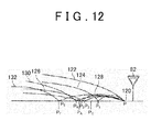
- FIG. 9 is a schematic view showing an example of the relationship between the remaining distance to the stopping position and the vehicle speed and types of assistance in the vehicle control system.
- FIG. 10 is a graph showing an example of a relationship between the distance Y and a coefficient K.
- the target calculation unit 54b calculates the target brake operation vehicle speed V_b on the basis of the current vehicle speed (the entrance vehicle speed) V_now of the vehicle 2.
- the target calculation unit 54b calculates the target brake operation starting vehicle speed V_b by multiplying the vehicle speed V_now by the predetermined vehicle speed coefficient.
- the target brake operation starting vehicle speed V_b can be calculated using an identical method to that of the embodiment described above.
- V_b correction value K from the estimated variation distance Y
- the V_b correction value K is a coefficient set in advance in relation to the estimated variation distance Y Further, a relationship between the V_b correction value K and the estimated variation distance Y is set such that the V_b correction value K and the estimated variation distance Y increase in a proportional relationship up to a point at which the estimated variation distance Y reaches a predetermined value Y1, but when the estimated variation distance Y exceeds the predetermined value Y1, the V_b correction value K remains at a fixed value K1. Furthermore, K takes a smaller value than 1, and therefore the target brake operation starting vehicle speed corrected value V_b' takes a lower speed value than the target brake operation starting vehicle speed V_b.
- the target calculation unit 54b calculates the target brake operation starting position X_b, which serves as the predetermined location, in step S134 on the basis of the target brake operation starting vehicle speed V_b and the preset target brake deceleration A_brake.
- the target calculation unit 54b calculates the target brake operation starting position X_b on the basis of the target brake operation starting vehicle speed V_b and the target brake deceleration A_brake using the reference stopping position (a location removed from the current location by the distance L) as a reference position.
- the target calculation unit 54b back-calculates a brake operation starting position at which, when the vehicle 2 traveling at the target brake operation starting vehicle speed V_b is decelerated by the target brake deceleration A_brake through a brake operation, the vehicle 2 can be stopped in the target stopping position, and sets the calculation result as the target brake operation starting position X_b.
- the target brake operation starting position X_b is identical to that of a case in which the reference stopping position is set as the target stopping position, or in other words the target brake operation starting position calculated using the deceleration pattern 100 of FIG. 9 .
- the target brake deceleration A_brake takes an identical value to that of the embodiment described above.
- the target calculation unit 54b calculates the accelerator OFF prompting position X_a' in step S136 on the basis of the target brake operation starting vehicle speed corrected value V_b', the target brake operation starting position X_b, and the preset prescribed accelerator OFF deceleration A_engBrakeD.
- the accelerator OFF deceleration A_engBrakeD takes an identical value to that of the embodiment described above.
- the target calculation unit 54b calculates the accelerator OFF prompting position X_a' on the basis of the accelerator OFF deceleration A_engBrakeD and the target brake operation starting vehicle speed corrected value V_b' using the target brake operation starting position X_b as a reference position. In other words, the target calculation unit 54b back-calculates an accelerator operation OFF position at which, when the vehicle 2 is decelerated by the accelerator OFF deceleration A_engBrakeD, the vehicle speed of the vehicle 2 can reach the target brake operation starting vehicle speed corrected value V_b' in the target brake operation starting position X_b, and sets the calculation result as the accelerator OFF prompting position X_a'.
- the target calculation unit 54b After calculating the accelerator OFF prompting position X_a' in step S136, the target calculation unit 54b starts the processing for outputting the driving assistance information using the HMI apparatus 4. In step S138, the target calculation unit 54b outputs driving assistance information relating to accelerator OFF prompting assistance to the HMI apparatus 4 at the timing at which the vehicle 2 reaches the accelerator OFF prompting position X_a' at the current vehicle speed.
- the HMI apparatus 4 displays the driving assistance information in the form of an HMI relating to the accelerator OFF prompting assistance.
- the braking/driving force control unit 54c performs braking/driving force control to adjust the actual deceleration of the vehicle 2 to the prescribed accelerator OFF D range deceleration A_engBrakeD.
- step S140 the braking/driving force control unit 54c according to this embodiment calculates the timing at which to switch engine braking, or in other words the timing at which to switch the accelerator OFF deceleration, on the basis of the current vehicle speed V_now of the vehicle 2 and the remaining distance L from the current position to the reference stopping position.
- the braking/driving force control unit 53c switches engine braking at a timing at which an inequality sign is established in (Equation 2) shown below, for example.
- the braking/driving force control unit 53c switches the accelerator OFF deceleration from the accelerator OFF D range deceleration A_engBrakeD to the accelerator OFF B range deceleration A_EngBrakeB.
- the braking/driving force control unit 54c then adjusts the actual deceleration of the vehicle 2 to the accelerator OFF B range deceleration A_EngBrakeB, whereupon the current control period is terminated and the routine shifts to the following control period.
- V_now denotes the current vehicle speed of the vehicle 2 following the accelerator operation OFF operation performed by the driver.
- V_b denotes the target brake operation starting vehicle speed corrected value.
- A_EngBrakeB denotes the accelerator OFF B range deceleration.
- L denotes the remaining distance to the reference stopping position from the current position at the actual timing of the accelerator operation OFF operation performed by the driver.
- X_b denotes the target brake operation starting position.
- the driving assistance apparatus 1 configured as described above, by displaying the accelerator OFF prompt in the location X_a', can provide prompting assistance in relation to the timing at which the driver is to perform the acceleration operation OFF operation such that the vehicle speed is at the target brake operation starting vehicle speed V_b when the vehicle 2 reaches the target brake operation starting position X_b'.
- the driving assistance apparatus 1 can prompt the driver appropriately such that when the driver actually performs a brake operation in order to stop in the stopping position, the degree of deceleration requested in accordance with the brake operation corresponds to the optimum target brake deceleration A_brake, and as a result, a superior fuel efficiency improvement effect can be realized.
- the driving assistance apparatus 1 configured as described above calculates the estimated variation distance Y and corrects the target brake operation starting vehicle speed V_b to the target brake operation starting vehicle speed corrected value V_b' in accordance with the estimated variation distance Y, whereby the vehicle speed upon arrival at the target brake operation starting position X_b can be reduced.
- the driver starts to decelerate the vehicle 2 at the optimum target brake deceleration A_brake in the target brake operation starting position X_b, and is therefore able to stop in front of the reference stopping position.
- a deceleration pattern 104 by setting the target brake operation starting vehicle speed corrected value V_b', the vehicle 2 can be stopped before the stopping position of the deceleration pattern 100 using an appropriate deceleration pattern.
- the target brake operation starting vehicle speed corrected value V_b' is calculated by correcting the target brake operation starting vehicle speed V_b on the basis of the estimated variation distance Y, but the invention is not limited thereto.
- the target calculation unit 54b calculates the target brake operation starting position X_b serving as the predetermined location on the basis of the target brake operation starting vehicle speed V_b and the preset target brake deceleration A_brake using the reference stopping position as a reference position.
- the target calculation unit 54b may also set a speed at which the vehicle 2 stops in a location removed from the current location by the distance L - Y after decelerating from the target brake operation starting position X_b at the target brake deceleration A_brake as the target brake operation starting vehicle speed corrected value on the basis of the target brake deceleration A_brake and the target brake operation starting position X_b using a target stopping position (a location removed from the current location by the distance L-Y) corresponding to the remaining distance as a reference.
- FIG. 11 is a flowchart showing an example of the control executed by the ECU
- FIG. 12 is an illustrative view showing examples of stopping patterns of the vehicle.
- processing shown in FIG. 11 may be performed by the respective units of the ECU 50, specifically the first information calculation unit 51, the second information calculation unit 52, and the third information calculation unit 53.
- the ECU 50 may include a separate calculation unit that determines the variation distance Y. Further, the ECU 50 executes the processing shown in FIG. 11 repeatedly during travel.
- step S202 the ECU 50 determines whether or not vehicle speed ⁇ threshold speed is established.
- the threshold speed is a speed at which the vehicle 2 is considered stationary.
- the vehicle speed can be obtained from the detection result of the vehicle speed sensor 10. After determining in step S202 that vehicle speed ⁇ threshold speed is not established (No), the ECU 50 terminates the processing.
- the ECU 50 After determining in step S202 that vehicle speed ⁇ threshold speed is established (Yes), the ECU 50 detects position information in step S204.
- the position information can be obtained from the detection result of the GPS apparatus 13.
- the ECU 50 determines whether or not the vehicle 2 is within a threshold distance of the stopping position in step S206. In other words, the ECU 50 determines whether or not the vehicle 2 is within a fixed distance from the stop line or the like set as the reference stopping position. Note that the ECU 50 preferably determines whether or not the stopping position exists within a fixed distance in front of the vehicle 2 in an advancement direction.
- the ECU 50 terminates the processing.
- the ECU 50 After determining in step S206 that the vehicle 2 is within the threshold distance of the stopping position (Yes), the ECU 50 detects an actual stopping position in step S208. In other words, the ECU 50 detects a stopping position on the near side of the reference position. After detecting the actual stopping position in step S208, the ECU 50 obtains information indicating accumulated actual stopping positions relating to the same position in step S210. In other words, the ECU 50 obtains data indicating actual stopping positions detected in the past in relation to the same reference stopping position.
- the ECU 50 After obtaining the data indicating the accumulated actual stopping positions in step S210, the ECU 50 obtains information relating to the reference stopping position in step S212, calculates the estimated variation distance Y in step S214, and after setting the calculated variation distance as the variation distance of the corresponding stopping position, terminates the processing.
- a reference stopping position 120 is set in the location P.
- the reference stopping position 120 is a position of a stop line, for example.
- six deceleration patterns (stopping patterns) 122, 124, 126, 128, 130, 132 are detected as stopping operations performed in relation to the reference stopping position 120.
- the deceleration pattern 122 the vehicle 2 stops in the location P serving as the reference stopping position 120.
- the deceleration pattern 124 the vehicle 2 initially stops in a location P 1 and then stops in the location P serving as the reference stopping position 120.
- the vehicle 2 In the deceleration pattern 126, the vehicle 2 initially stops in a location P 2 and then stops in the location P serving as the reference stopping position 120. In the deceleration pattern 128, the vehicle 2 initially stops in a location P 3 and then stops in the location P serving as the reference stopping position 120. In the deceleration pattern 130, the vehicle 2 initially stops in a location P 4 and then stops in the location P serving as the reference stopping position 120. In the deceleration pattern 132, the vehicle 2 initially stops in a location P 5 and then stops in the location P serving as the reference stopping position 120.
- the ECU 50 having detected the six deceleration patterns (stopping patterns) 122, 124, 126, 128, 130, 132, accumulates information indicating the six locations P, P 1 , P 2 , P 3 , P 4 , P 5 as actual stopping positions.
- the location P serving as the reference stopping position 120 is a position of a temporary stop, and therefore the respective stops in the location P in the deceleration patterns 124, 126, 128, 130, 132 are not detected as actual stopping positions.
- the ECU 50 calculates a location P C serving as a median value of the actual stopping positions, and sets a distance between the median value location Pc and the actual stopping position P F furthest from the reference stopping position P as the variation distance Y.
- L
- the median value location P C is an intermediate location between an actual stopping position closest to the reference stopping position and the actual stopping position furthest from the reference stopping position.
- the median value location P C is set as an intermediate location between the actual stopping position P of the deceleration pattern 122 and the actual stopping position P F of the deceleration pattern 132.
- the method of calculating the variation distance Y is not limited to the method described above, and instead, a standard deviation of the actual stopping positions may be calculated, whereupon a standard deviation ⁇ or a distance corresponding to 3 ⁇ is set as the variation distance Y Furthermore, the ECU 50 may set a distance from the reference stopping position to the median value location P C as the variation distance Y.
- the driving assistance apparatus 1 can provide the driver with more favorable stopping assistance.
- the driving assistance apparatus 1 can perform a correction based on the reference target position.
- a situation in which stopping assistance is provided in a different location to the location where the vehicle 2 must actually stop can be prevented.
- a situation in which a stop on a road that is constantly congested or the like is detected as an actual stopping position such that stopping assistance is executed in a location that is not a position where the vehicle 2 must stop can be suppressed.
- FIG. 13 is a flowchart showing an example of the control executed by the ECU. Note that the processing shown in FIG. 13 can be realized by processing performed in conjunction by the plurality of calculation units of the ECO 50. Further, the processing shown in FIG. 13 is an example of a case in which the target stopping position is varied on the basis of the variation distance Y, but similar processing can be executed in a case where a brake starting target speed is varied on the basis of the variation distance Y.
- the ECU 50 detects the position information in step S220, and determines whether or not a stopping position exists in the advancement direction in S222.
- the stopping position includes a position of a red traffic light and a position of a temporary stop. Further, the ECU 50 uses a range of a fixed distance as a subject. After determining that a stopping position does not exist (No) in step S222, the ECU 50 advances to S220 and executes the processing of step S220 again.
- step S222 After determining that a stopping position exists (Yes) in step S222, the ECU 50 obtains the information indicating the reference stopping position in step S224, and determines whether or not the variation distance has been set in step S226. In other words, the ECU 50 determines whether or not a variation distance calculation result is associated with the reference stopping position obtained in step S224. After determining that the variation distance has not been set (No) in step S226, the ECU 50 sets the reference stopping position as the target stopping position in step S228, and then terminates the processing.
- step S236 After determining that the variation distance has been set (Yes) in step S226, the ECU 50 obtains the information indicating the variation distance in step S230, and then determines whether or not a preceding vehicle exists in step S232. Note that the presence of a preceding vehicle may be determined on the basis of the detection value of the millimeter wave sensor 16. Further, the ECU 50 determines that a preceding vehicle exists when the preceding vehicle exists within a fixed distance, and determines that a preceding vehicle does not exist when the preceding vehicle exists beyond the fixed distance or a preceding vehicle is not detected. After determining that a preceding vehicle does not exist (No) in step S232, the ECU 50 advances to step S236.
- step S232 After determining that a preceding vehicle exists (Yes) in step S232, the ECU 50 corrects the variation distance in step S234, and then advances to step S236.
- the ECU 50 performs processing to lengthen the variation distance. In so doing, it is possible to respond to a situation in which a preceding vehicle exists such that the stopping position shifts to the near side.
- the ECU 50 After determining No in step S232 or after executing the processing of step S234, the ECU 50 sets the target stopping position on the basis of the reference stopping position and the estimated variation distance, or in other words sets the target stopping position as L - Y, in step S236, and then terminates the processing.
- the driving assistance apparatus 1 can obtain the effects described above.
- the variation distance can be corrected in accordance with conditions during actual travel, and as a result, the stopping assistance can be improved in precision. Note that the variation distance does not necessarily have to be corrected on the basis of whether or not a preceding vehicle exists.
- the driving assistance apparatus 1 may be configured to vary the estimated variation distance set for each stopping position further in time zone intervals.
- FIG. 14 is an illustrative view showing an example of a relationship between the estimated variation distance and time
- FIG. 15 is a flowchart showing an example of the control executed by the ECU.
- the driving assistance apparatus 1 calculates the variation distance by accumulating the information indicating the actual stopping positions in respective time zones of a single day.
- a single day is divided into six time zones, and variation distances calculated on the basis of the actual stopping positions detected in the respective time zones are stored.
- the ECU 50 performs processing shown in FIG. 15 when executing step S230 of FIG. 13 . More specifically, the ECU 50 detects the position information and the time in step S240, calculates a variation distance corresponding to the time in step S242, and then terminates the processing. In other words, the ECU 50 specifies the subject stopping position on the basis of the position information, and then obtains a table such as that shown in FIG. 14 set in relation to the specified stopping position. The ECU 50 then obtains the corresponding variation distance on the basis of the obtained table and the time information.
- the driving assistance apparatus 1 can calculate and set a variation distance that corresponds to an amount of traffic, which varies according to the time zone. As a result, stopping assistance can be performed in accordance with the time zone.
- the estimated variation distance is varied by dividing a single day into periods of several hours.
- the invention is not limited thereto, however, and the time may be divided into days of the week or weekdays and weekends.
- the driving assistance apparatus according to the embodiments of the invention described above is not limited to the above embodiments, and may be subjected to various modifications within the scope of the claims.
- the driving assistance apparatus according to these embodiments may be configured by appropriately combining constituent elements of the respective embodiments described above.
- the ECU 50 doubles as an assistance control apparatus and a deceleration control apparatus, but the invention is not limited thereto, and instead, for example, the assistance control apparatus and the deceleration control apparatus may be configured separately to the ECU 50 and configured to exchange information such as detection signals, drive signals, and control commands.
- the target travel condition quantity is the target brake operation starting vehicle speed, which is a recommended vehicle speed at which the driver is recommended to perform the brake operation (the braking request operation).
- the invention is not limited thereto, however, and any target condition quantity representing a travel condition of the vehicle, for example a target vehicle acceleration/deceleration, a target shift ratio (a target gear position), a target operating angle, and so on, may be used instead.
- the recommended driving operation in relation to which the driving assistance apparatus provides the driver with prompting assistance is the accelerator operation OFF operation (the operation for canceling the acceleration request operation) performed by the driver.
- the invention is not limited thereto, however, and the recommended driving operation in relation to which the driving assistance apparatus provides the driver with prompting assistance may, for example, be the acceleration request operation, the braking request operation, the operation for canceling the braking request operation, a shift operation, a steering operation, and so on.
- the driving assistance apparatus outputs visual information as the driving assistance information
- the invention is not limited thereto, and instead, for example, the driving assistance apparatus may output audio information, sensory information, and so on as the driving assistance information, and the form of the audio information or sensory information may be varied appropriately.
- the driving assistance apparatus 1 uses the millimeter wave sensor 16 as preceding vehicle detecting means for detecting a preceding vehicle (a frontward vehicle), but the invention is not limited thereto, and a camera that obtains images ahead of the vehicle 2 may be used as the preceding vehicle detecting means. In this case, the driving assistance apparatus 1 may analyze an image obtained by the camera in order to detect a preceding vehicle in front of the vehicle 2 in the advancement direction.
Landscapes
- Engineering & Computer Science (AREA)
- Automation & Control Theory (AREA)
- Transportation (AREA)
- Mechanical Engineering (AREA)
- Physics & Mathematics (AREA)
- General Physics & Mathematics (AREA)
- Life Sciences & Earth Sciences (AREA)
- Atmospheric Sciences (AREA)
- Human Computer Interaction (AREA)
- Control Of Driving Devices And Active Controlling Of Vehicle (AREA)
- Traffic Control Systems (AREA)
- Electric Propulsion And Braking For Vehicles (AREA)
Abstract
Description
- The invention relates to a driving assistance apparatus.
- A conventional driving assistance apparatus is installed in a vehicle in order to output information for assisting a driver in driving the vehicle.
Patent Document 1, for example, describes an apparatus that accumulates detection results from vehicle speed and position sensors and determines a condition of an intersection as this type of conventional driving assistance apparatus. Further,Patent Document 1 describes extracting a plurality of locations at which the vehicle speed is at a minimum within a predetermined range of the intersection, and setting an average position of the extracted positions as a target stopping position at which to stop temporarily.Patent Document 2 discloses an apparatus that notifies a driver of a point at which to start decelerating when it is necessary to stop at a traffic light on the basis of a time required to reach the traffic light and a time remaining until a color of the traffic light changes. - Patent Document 1: Japanese Patent Application Publication No.
2005-174282 JP 2005-174282 A - Patent Document 2: Japanese Patent Application Publication No.
2010-244308 JP 2010-244308 A - Incidentally, although the apparatus described in
Patent Document 2 can detect a location of a temporary stop by setting a target stopping position on the basis of the accumulated detection results from the vehicle speed and position sensors, there remains room for improvement in terms of providing more appropriate driving assistance, for example. Further, although the apparatus described inPatent Document 2 provides assistance to prompt early deceleration by notifying the driver of the point at which to start decelerating when it is necessary to stop at a traffic light, there remains room for improvement in terms of providing more appropriate driving assistance, for example. - The invention has been designed in consideration of the circumstances described above, and an object thereof is to provide a driving assistance apparatus that can provide driving assistance appropriately.
- To achieve the object described above, a driving assistance apparatus according to the invention assists driving of a vehicle, and includes: an assistance control apparatus that accumulates vehicle stopping position information, which is information indicating an actual stopping position in which the vehicle stops in relation to a reference stopping position, calculates an estimated variation distance between the actual stopping position and the reference stopping position on the basis of the accumulated vehicle stopping position information, and creates a target vehicle travel condition in which a timing at which stopping assistance is started is varied on the basis of the estimated variation distance; and an assistance apparatus that is capable of outputting driving assistance information to assist driving of the vehicle on the basis of a target travel condition quantity calculated by the assistance control apparatus.
- Further, the assistance control apparatus preferably varies the timing at which the stopping assistance is started by determining a target stopping position on the basis of a difference between the estimated variation distance and the reference stopping position, and creating the target vehicle travel condition on the basis of the target stopping position.
- Further, the assistance control apparatus preferably varies the timing at which the stopping assistance is started by correcting a target vehicle speed at the start of a brake operation on the basis of the estimated variation distance, and creating the target vehicle travel condition on the basis of the corrected target vehicle speed at the start of the brake operation.
- Further, the estimated variation distance is preferably a distance from a position of an average value of the actual stopping positions to an actual stopping position furthest from the reference stopping position.
- Further, the estimated variation distance is preferably a distance from a position of a median value of the actual stopping positions to a location furthest from the reference stopping position.
- Further, the assistance control apparatus preferably sets the target stopping position in a position shifted from the reference stopping position to a near side by the estimated variation distance.
- Further, the driving assistance apparatus preferably further includes preceding vehicle detecting means for detecting a preceding vehicle traveling in front of the vehicle in an advancement direction of the vehicle, and when the preceding vehicle detecting means detects a preceding vehicle, the assistance control apparatus preferably advances the timing at which the stopping assistance is started.
- Further, when the preceding vehicle detecting means detects a preceding vehicle, the assistance control apparatus preferably shifts the target stopping position to the near side with respect to the reference stopping position.
- Further, the assistance control apparatus preferably classifies the information indicating the actual stopping positions into set time patterns, calculates the estimated variation distance for each of the patterns, and creates the target vehicle travel condition on the basis of the estimated variation distance of the time pattern in which a creation time of the target vehicle travel condition is classified.
- Further, the assistance apparatus preferably performs assistance to prompt a recommended driving operation by outputting the driving assistance information.
- Further, the driving assistance information preferably includes information instructing cancelation of an acceleration request operation and a braking request operation.
- Further, the driving assistance information preferably includes information instructing starting of the braking request operation.
- The driving assistance apparatus according to the invention is capable of providing driving assistance appropriately.
-
- [
FIG. 1] FIG. 1 is a schematic view showing a configuration of a vehicle control system. - [
FIG. 2] FIG. 2 is a schematic block diagram showing an example of a configuration of an electronic control unit (ECU). - [
FIG. 3] FIG. 3 is a schematic block diagram showing an example of a configuration of a target calculation unit. - [
FIG. 4] FIG. 4 is a schematic view showing a relationship between a remaining distance to a stopping position and a vehicle speed. - [
FIG. 5] FIG. 5 is a schematic view showing the relationship between the remaining distance to the stopping position and the vehicle speed. - [
FIG. 6] FIG. 6 is a flowchart showing an example of control executed by the ECU. - [
FIG. 7] FIG. 7 is a schematic view showing an example of the relationship between the remaining distance to the stopping position and the vehicle speed and types of assistance in the vehicle control system. - [
FIG. 8] FIG. 8 is a flowchart showing another example of the control executed by the ECU. - [
FIG. 9] FIG. 9 is a schematic view showing another example of the relationship between the remaining distance to the stopping position and the vehicle speed and types of assistance in the vehicle control system. - [
FIG. 10] FIG. 10 is a graph showing an example of a relationship between a distance Y and a coefficient K. - [
FIG. 11] FIG. 11 is a flowchart showing an example of the control executed by the ECU. - [
FIG. 12] FIG. 12 is an illustrative view showing examples of stopping patterns of the vehicle. - [
FIG. 13] FIG. 13 is a flowchart showing an example of the control executed by the ECU. - [
FIG. 14] FIG. 14 is an illustrative view showing an example of a relationship between an estimated variation distance and time. - [
FIG. 15] FIG. 15 is a flowchart showing an example of the control executed by the ECU. - Embodiments of the invention will be described in detail below on the basis of the drawings. Note that the invention is not limited to these embodiments. Further, constituent elements of the following embodiments include elements that could be replaced easily by a person skilled in the art or substantially identical elements.
-
FIG. 1 is a schematic view showing a configuration of a vehicle control system according to a first embodiment,FIG. 2 is a schematic block diagram showing an example of a configuration of an ECU according to the first embodiment, andFIG. 3 is a schematic block diagram showing an example of a configuration of a target calculation unit. - As shown in
FIG. 1 , adriving assistance apparatus 1 according to this embodiment is applied to avehicle control system 3 installed in avehicle 2. Thedriving assistance apparatus 1 includes a human machine interface (HMI) apparatus (also referred to hereafter as an "HMI") 4 serving as an assistance apparatus, and anECU 50. Thedriving assistance apparatus 1 assists a driver in driving thevehicle 2 by having the ECU 50 control theHMI apparatus 4 in accordance with conditions to output various types of driving assistance information. - The
vehicle control system 3 to which thedriving assistance apparatus 1 according to this embodiment is applied is a read-ahead information eco-driving assistance system that utilizes so-called read-ahead information. In other words, thevehicle control system 3 utilizes read-ahead information to cause thedriving assistance apparatus 1 to provide assistance to prompt the driver to perform driving operations having a superior fuel efficiency improvement effect, and in so doing, assists the driver in performing eco-driving. Hence, thevehicle control system 3 is a system configured to suppress fuel consumption and thereby achieve an improvement in fuel efficiency. Thedriving assistance apparatus 1 typically provides assistance to prompt an operation by the driver by outputting driving assistance information with the aim of assisting the driver in performing eco-driving. - Further, the
vehicle control system 3 according to this embodiment is a so-called hybrid system in which a travel drive source for driving a drive wheel of thevehicle 2 to rotate is constituted by a combination of anengine 5 and a motor generator (MG) 6. In other words, thevehicle 2 is a hybrid vehicle including the MG 6 as a travel drive source in addition to theengine 5. Thevehicle 2 is configured to realize an improvement in fuel efficiency by operating theengine 5 in a maximum efficiency condition, compensating for deficiency and excess in an amount of power and an engine braking force using the MG 6, which is a rotating electric machine, and regenerating energy during deceleration. - Note that although the
vehicle control system 3 will be described below as a hybrid system including theengine 5 and the MG 6 as travel drive sources, thevehicle control system 3 is not limited thereto and may be a system that includes theengine 5 as a travel drive source but does not include the MG 6, or a system that includes the MG 6 as a travel drive source but does not include theengine 5. In other words, thevehicle 2 may be a so-called conventional vehicle or a so-called EV (electric vehicle). - More specifically, the
vehicle control system 3 is configured to include theHMI apparatus 4, theengine 5, which is constituted by an internal combustion engine, the MG 6, which is constituted by a motor, atransmission 7, abrake apparatus 8, abattery 9, and so on. Thevehicle control system 3 also includes avehicle speed sensor 10, anaccelerator sensor 11, abrake sensor 12, a global positioning system (GPS) apparatus (also referred to hereafter as a "GPS") 13, awireless communication apparatus 14, a database (DB) 15, amillimeter wave sensor 16, and so on. - The
HMI apparatus 4 is an assistance apparatus capable of outputting driving assistance information, which is information used to assist driving of thevehicle 2. The HMIapparatus 4 provides the driver with the driving assistance information and so on. TheHMI apparatus 4 is an in-vehicle device, and includes a display apparatus (a visual information display apparatus), a speaker (an audio output apparatus), and so on provided in a cabin of thevehicle 2, for example. Existing apparatuses such as a display apparatus, a speaker, and so on of a navigation (NAVI) system, for example, may be used as is as theHMI apparatus 4. TheHMI apparatus 4 prompts the driver to perform a driving operation by providing information such as voice information and visual information (pictorial information and alphabetical information) so that an improvement in fuel efficiency can be achieved. By providing this information, theHMI apparatus 4 assists the driver in achieving target values through his/her driving operations. TheHMI apparatus 4 is electrically connected to theECU 50 and controlled by theECU 50. Note that theHMI apparatus 4 may be configured to include a sensory information output apparatus or the like that outputs sensory information such as steering wheel vibration, seat vibration, a pedal reaction force, and so on, for example. - The
engine 5, theMG 6, thetransmission 7, thebrake apparatus 8, thebattery 9, and so on are installed in thevehicle control system 3 as various actuators for realizing travel by thevehicle 2. - The
engine 5 causes a driving force to act on a wheel of thevehicle 2 in response to an acceleration request operation, for example an accelerator pedal depression operation, performed by the driver. Theengine 5 consumes fuel to generate engine torque that serves as travel power applied to a drive wheel of thevehicle 2. In other words, theengine 5 is a heat engine that outputs thermal energy generated by burning fuel in the form of mechanical energy such as torque, and may be constituted by a gasoline engine, a diesel engine, a liquefied petroleum gas (LPG) engine, or the like, for example. Theengine 5 includes, for example, a fuel injection apparatus, an ignition apparatus, a throttle valve apparatus, and so on, not shown in the drawings, and these apparatuses are electrically connected to theECU 50 so as to be controlled by theECU 50. An output torque from theengine 5 is controlled by theECU 50. Note that the power generated by theengine 5 may be used during power generation by theMG 6. - The
MG 6 causes a driving force to act on the wheel of thevehicle 2 in response to the acceleration request operation, for example the accelerator pedal depression operation, performed by the driver. TheMG 6 converts electric energy into mechanical power to generate motor torque that serves as the travel power applied to the drive wheel of thevehicle 2. TheMG 6 is a so-called rotating electric machine having a stator as a fixed element and a rotor as a rotary element. TheMG 6 is both a motor that converts electric energy into mechanical power and outputs the mechanical power, and a power generator that converts mechanical power into electric energy and collects the electric energy. In other words, theMG 6 functions as both a motor that is driven by a supply of power to convert electric energy into mechanical energy and output the mechanical energy (a power running function), and a power generator that converts mechanical energy into electric energy (a regenerative function). TheMG 6 is electrically connected to theECU 50 via an inverter or the like that performs conversion between a direct current and an alternating current, and is thus controlled by theECU 50. An output torque and a power generation amount of theMG 6 are controlled by theECU 50 via the inverter. - The
transmission 7 is a power transmission apparatus that speed-shifts a rotary output generated by theengine 5 and theMG 6 and transmits the speed-shifted rotary output to the drive wheel side of thevehicle 2. Thetransmission 7 may be a so-called manual transmission (MT), or a so-called automatic transmission (AT) such as a stepped AT, a continuously variable transmission (CVT), a multimode manual transmission (MMT), a sequential manual transmission (SMT), or a dual clutch transmission (DCT). It is assumed in the following description that thetransmission 7 is a CVT employing a planetary gear mechanism and so on, for example. A transmission actuator or the like of thetransmission 7 is electrically connected to theECU 50 such that thetransmission 7 is controlled by theECU 50. - The
brake apparatus 8 causes a braking force to act on the wheel of thevehicle 2 in response to a braking request operation, for example a brake pedal depression operation, performed by the driver. Thebrake apparatus 8 applies the braking force to the wheel, which is supported rotatably on a vehicle body of thevehicle 2, by generating a predetermined frictional force (a frictional resistance force) between friction elements such as brake pads or brake discs, for example. In so doing, thebrake apparatus 8 generates a braking force on a ground contact surface of the vehicle wheel of thevehicle 2, i.e. a surface of the vehicle wheel that contacts a road surface, and as a result, braking can be applied to thevehicle 2. A brake actuator or the like of thebrake apparatus 8 is electrically connected to theECU 50 such that thebrake apparatus 8 is controlled by theECU 50. - The
battery 9 is a storage apparatus capable of storing power (storage) and discharging the stored power. Thebattery 9 is electrically connected to theECU 50 in order to output signals relating to various types of information to theECU 50. - When the
MG 6 functions as a motor, the power stored in thebattery 9 is supplied thereto via the inverter, whereupon theMG 6 converts the supplied power into travel power for thevehicle 2 and outputs the travel power. When theMG 6 functions as a power generator, on the other hand, theMG 6 is driven by input power to generate power and charge thebattery 9 with the generated power via the inverter. At this time, braking (regenerative braking) can be applied to rotation of the rotor of theMG 6 using rotational resistance generated in the rotor. During the regenerative braking, therefore, regenerative motor torque, which is negative motor torque, can be generated in the rotor of theMG 6 through power regeneration, and as a result, a braking force can be applied to the drive wheel of thevehicle 2. In other words, in thevehicle control system 3, mechanical power is input into theMG 6 from the drive wheel of thevehicle 2, causing theMG 6 to generate power by regeneration, and as a result, kinetic energy of thevehicle 2 can be collected as electric energy. Further, in thevehicle control system 3, the mechanical power (the negative motor torque) generated in the rotor of theMG 6 during the operation described above can be transmitted to the drive wheel, and as a result, regenerative braking can be performed by theMG 6. In this case, the braking force generated in thevehicle control system 3 decreases relatively as a regeneration amount (a power generation amount) of theMG 6 is relatively reduced, and as a result, a degree of deceleration acting on thevehicle 2 decreases relatively. On the other hand, the braking force generated in thevehicle control system 3 increases relatively as the regeneration amount (the power generation amount) of theMG 6 is relatively increased, and as a result, the degree of deceleration acting on thevehicle 2 increases relatively. - The
vehicle speed sensor 10, theaccelerator sensor 11, and thebrake sensor 12 are condition detection apparatuses that detect travel conditions of thevehicle 2 and input (driver input) that is input into thevehicle 2 by the driver, or in other words condition quantities and physical quantities relating to actual operations performed by the driver on thevehicle 2. Thevehicle speed sensor 10 detects a speed (also referred to as the "vehicle speed" hereafter) of thevehicle 2. Theaccelerator sensor 11 detects an accelerator opening, i.e. an operation amount (a depression amount) of the accelerator pedal by the driver. Thebrake sensor 12 detects an operation amount (a depression amount) of the brake pedal by the driver, for example a master cylinder pressure or the like. Thevehicle speed sensor 10, theaccelerator sensor 11, and thebrake sensor 12 are electrically connected to theECU 50 in order to output detection signals to theECU 50. - The
GPS apparatus 13 is an apparatus that detects a current position of thevehicle 2. TheGPS apparatus 13 receives a GPS signal output by a GPS satellite, and on the basis of the received GPS signal, measures/calculates GPS information (X coordinate; X, Y coordinate; Y) serving as information indicating the position of thevehicle 2. TheGPS apparatus 13 is electrically connected to theECU 50 in order to output a signal relating to the GPS information to theECU 50. - The
wireless communication apparatus 14 is a read-ahead information acquisition apparatus that obtains read-ahead information relating to travel by thevehicle 2 using wireless communication. For example, thewireless communication apparatus 14 uses wireless communication to obtain the read-ahead information from an apparatus that exchanges information using a communication infrastructure such as the Internet via a road-to-vehicle communication device (a roadside device) such as an optical beacon disposed on a roadside, a vehicle-to-vehicle communication device installed in another vehicle, a vehicle information and communication system (VICS) (registered trademark) center, or the like. As the read-ahead information, thewireless communication apparatus 14 obtains, for example, preceding vehicle information, following vehicle information, traffic light information, works/traffic restriction information, congestion information, emergency vehicle information, information relating to an accident history DB, and so on. The traffic light information includes, for example, information indicating a position of a traffic light ahead of thevehicle 2 in a travel direction, light cycle information indicating an illumination cycle, a light switch timing, and so on of a green light, a yellow light, and a red light, and so on. Thewireless communication apparatus 14 is electrically connected to theECU 50 in order to output signals relating to the read-ahead information to theECU 50. - The
DB 15 stores various information. TheDB 15 stores map information including road information, various information and learned information obtained during actual travel by thevehicle 2, the read-ahead information obtained by thewireless communication apparatus 14, and so on. The road information includes, for example, road gradient information, road surface condition information, road shape information, speed limit information, road curvature (curve) information, temporary stop information, stop line position information, and so on. The information stored in theDB 15 is referred to appropriately by theECU 50, whereupon required information is read. Note that here, as shown in the drawing, theDB 15 is installed in thevehicle 2, but the invention is not limited thereto, and theDB 15 may be provided in an information center or the like outside thevehicle 2. In this case, theDB 15 is referred to appropriately by theECU 50 via wireless communication or the like, whereupon the required information is read. As the learned information, theDB 15 according to this embodiment accumulates information indicating a position (an actual stopping position) in which thevehicle 2 stops at a traffic light, an intersection, or the like provided with a reference stopping position such as a stop line. TheDB 15 accumulates the actual stopping position information for each reference stopping position. - The
millimeter wave sensor 16 is a sensor that measures an inter-vehicle distance between a host vehicle and a preceding vehicle (a vehicle ahead of the vehicle 2). Themillimeter wave sensor 16 emits millimeter waveband radio waves frontward from thevehicle 2 such that the emitted radio waves are reflected by an object (the preceding vehicle, i.e. a frontward vehicle), and receives the returning radio waves. Themillimeter wave sensor 16 calculates the distance to the frontward vehicle by comparing an output condition of the emitted radio waves with a detection result of the received radio waves. Themillimeter wave sensor 16 may also detect a distance to an obstruction in front of the host vehicle. Themillimeter wave sensor 16 transmits information indicating the calculated distance to the frontward vehicle to theECU 50. Note that in this embodiment, themillimeter wave sensor 16 is used as a sensor that measures the inter-vehicle distance between the host vehicle and the preceding vehicle (the vehicle ahead of the vehicle 2), but various sensors capable of measuring a distance to an object in front of thevehicle 2 may be used instead. For example, thevehicle 2 may employ a laser radar sensor in place of themillimeter wave sensor 16. - The
ECU 50 is a control unit that performs overall control of thevehicle control system 3, and is constituted, for example, by an electronic circuit having a conventional microcomputer including a central processing unit (CPU), a read only memory (ROM), a random access memory (RAM), and an interface as a main body. Electric signals corresponding to detection results obtained by thevehicle speed sensor 10, theaccelerator sensor 11, thebrake sensor 12, and themillimeter wave sensor 16, the GPS information obtained by theGPS apparatus 13, the read-ahead information obtained by thewireless communication apparatus 14, the various information stored in theDB 15, drive signals relating to respective components, control commands, and so on are input into theECU 50. TheECU 50 controls theHMI apparatus 4, theengine 5, theMG 6, thetransmission 7, thebrake apparatus 8, thebattery 9, and so on in accordance with the input electric signals and so on. For example, theECU 50 executes drive control on theengine 5, drive control on theMG 6, shift control on thetransmission 7, braking control on thebraking apparatus 8, and the like on the basis of the accelerator depression amount, the vehicle speed, and so on. Further, for example, theECU 50 realizes various types of vehicle travel (travel modes) in thevehicle 2 by employing theengine 5 and theMG 6 either together or selectively in accordance with operating conditions. - Furthermore, for example, the
ECU 50 can detect an ON/OFF condition of an accelerator operation serving as the acceleration request operation performed on thevehicle 2 by the driver on the basis of the detection result obtained by theaccelerator sensor 11. Similarly, for example, theECU 50 can detect an ON/OFF condition of a brake operation serving as the braking request operation performed on thevehicle 2 by the driver on the basis of the detection result obtained by thebrake sensor 12. Note that when the accelerator operation performed by the driver is in an OFF condition, this means that the driver has canceled the acceleration request operation in relation tovehicle 2, and when the accelerator operation performed by the driver is in an ON condition, this means that the driver is performing the acceleration request operation on thevehicle 2. Similarly, when the brake operation performed by the driver is in an OFF condition, this means that the driver has canceled the braking request operation in relation to thevehicle 2, and when the brake operation performed by the driver is in an ON condition, this means that the driver is performing the braking request operation on thevehicle 2. - As described above, the driving
assistance apparatus 1 is configured to include theHMI apparatus 4 and theECU 50. In addition to theHMI apparatus 4 and theECU 50, the drivingassistance apparatus 1 may include various sensors for detecting vehicle conditions and various information acquisition units for supplying peripheral information. The drivingassistance apparatus 1 provides assistance to prompt the driver to perform driving operations having a superior fuel efficiency improvement effect by having theECU 50 control theHMI apparatus 4 in accordance with conditions such that various types of driving assistance information are output. The drivingassistance apparatus 1 provides prompting assistance to prompt the driver to perform a recommended driving operation, which is typically a driving operation performed in response to a change, on the basis of a target travel condition quantity of thevehicle 2 during travel by causing theHMI apparatus 4 to output the various types of driving assistance information in accordance with the control executed by theECU 50. Here, the target travel condition quantity of thevehicle 2 is typically a target travel condition quantity of thevehicle 2 during travel at a predetermined location or a predetermined timing. The drivingassistance apparatus 1 provides assistance to prompt the driver to perform the recommended driving operation by having theECU 50 control theHMI apparatus 4 on the basis of the target travel condition quantity at the predetermined location or the predetermined timing such that theHMI apparatus 4 outputs the driving assistance information, and in so doing, the drivingassistance apparatus 1 provides driving assistance with which the travel condition quantity of thevehicle 2 reaches the target travel condition quantity at the predetermined location and the predetermined timing. - When the
vehicle 2 is to be stopped in a stopping position at a traffic light, an intersection, or the like, the drivingassistance apparatus 1 according to this embodiment varies (shifts) a target stopping position from a reference stopping position (a position of a stop line) on the basis of various conditions. More specifically, the drivingassistance apparatus 1 calculates an estimated variation distance (also referred to as a variation distance) Y, and sets a position shifted from the reference stopping position to a near side (a side of a current position of the vehicle 2) by the calculated estimated variation distance as the target stopping position. - The driving
assistance apparatus 1 determines the target travel condition quantity, which is a predetermined travel condition in a predetermined position, on the basis of the varied target stopping position. The drivingassistance apparatus 1 then outputs the driving assistance information on the basis of the target travel condition. Note that the drivingassistance apparatus 1 according to this embodiment outputs the driving assistance information to theHMI apparatus 4 as visual information. Here, a target brake operation starting vehicle speed, i.e. a recommended vehicle speed at which the driver is recommended to perform the brake operation (the braking request operation) may be cited as an example of the target travel condition quantity. Further, an operation performed by the driver to switch the accelerator operation OFF (i.e. an operation to cancel the acceleration request operation) may be cited as an example of the recommended driving operation which the drivingassistance apparatus 1 prompts the driver to perform. The drivingassistance apparatus 1 displays the visual information serving as the driving assistance information in the form of an image on a visual information display apparatus such as a center meter, a head-up display (HUD), a display superimposed onto a front windshield, or a liquid crystal display constituting theHMI apparatus 4, for example. - The
vehicle 2 outputs information instructing the driver to perform the operation for switching the accelerator operation OFF as the driving assistance information, thereby causing the driver to execute the operation for switching the accelerator operation OFF in a predetermined position. As a result, the vehicle speed substantially reaches the target brake operation starting vehicle speed in the predetermined location. When the vehicle speed substantially reaches the target brake operation starting vehicle speed in the predetermined location, the driver starts the brake operation in the predetermined position where the target brake operation starting vehicle speed is reached, and as a result, thevehicle 2 can be stopped smoothly in the vicinity of the target stopping position. Hence, the driving assistance information is output such that thevehicle 2 stops appropriately in the target stopping position corresponding to the various conditions. The drivingassistance apparatus 1 thus realizes appropriate driving assistance in which a sense of discomfort experienced by the driver during driving assistance is suppressed. - An example of a configuration of the
ECU 50 will be described in outline below with reference to the block diagram ofFIG. 2 . As shown inFIG. 2 , theECU 50 is configured to include a firstinformation calculation unit 51, a secondinformation calculation unit 52, a thirdinformation calculation unit 53, and avehicle control unit 54. The firstinformation calculation unit 51, secondinformation calculation unit 52, and thirdinformation calculation unit 53 are intelligent transport systems (ITS) compatible calculation units, for example, which are used to perform infrastructure cooperation and NAVI cooperation. Thevehicle control unit 54 is a control unit that controls respective parts of thevehicle 2. Thevehicle control unit 54 is connected via a control area network (CAN) 55, which is constructed as an in-vehicle network, to an actuator ECU and various sensors for controlling various actuators such as an engine control ECU, an MG control ECU, a transmission control ECU, a brake control ECU, and a battery control ECU. Thevehicle control unit 54 obtains control values of the various actuators and detection values from the sensors as vehicle information via theCAN 55. Note that theECU 50 is not limited to this configuration, and may be configured to include a NAVI apparatus instead of the firstinformation calculation unit 51, for example. - The first
information calculation unit 51 calculates a remaining distance to a temporary stop or a curve in front of thevehicle 2 in the travel direction on the basis of static infrastructure information, for example the map information including the road information and so on. Further, the firstinformation calculation unit 51 learns and predicts deceleration/stopping behavior of the driver by learning usual driving behavior of the driver and estimating driving behavior on the basis thereof. The firstinformation calculation unit 51 also calculates a remaining distance to a deceleration/stopping position in front of thevehicle 2 in the travel direction. Here, the deceleration/stopping position obtained by learning the usual driving behavior of the driver is a position other than a temporary stop or the like in which the driver decelerates and stops frequently, for example. - Note that the first
information calculation unit 51 may learn the deceleration/stopping behavior of the driver on the basis of various information obtained while thevehicle 2 actually travels, or in other words may learn a deceleration/stopping position corresponding to the driver. For example, on the basis of various information obtained while thevehicle 2 actually travels, the firstinformation calculation unit 51 learns habits and tendencies of driving operations performed by the driver during normal driving in association with the person (driver attributes, for example), the location (the position in which the operation is performed and so on, for example), the conditions (the time and so on, for example), and so on. For example, the firstinformation calculation unit 51 learns temporary stops, deceleration/stopping positions in which the driver frequently decelerates and stops, and so on by performing statistical processing in relation to the ON/OFF condition of the accelerator operation and the brake operation performed by the driver, and so on. The firstinformation calculation unit 51 stores the learned information in theDB 15 as learned information. - The first
information calculation unit 51 includes, as basic functions, aposition evaluation unit 51a, a temporary stop/curveinformation acquisition unit 51b, and asubtractor 51c. Theposition evaluation unit 51a obtains information indicating the current position of the vehicle (the host vehicle) 2 by obtaining the GPS information via theGPS apparatus 13. Theposition evaluation unit 51a outputs the current position information to the temporary stop/curveinformation acquisition unit 51b and thesubtractor 51c. The temporary stop/curveinformation acquisition unit 51b refers to the map information, the various information obtained as thevehicle 2 actually travels, and the learned information stored in theDB 15 on the basis of the current position information input from theposition evaluation unit 51a to obtain target position information indicating a temporary stop, a curve, or a deceleration/stopping position in front of thevehicle 2 in the travel direction. The temporary stop/curveinformation acquisition unit 51b outputs the target position information to thesubtractor 51c. Thesubtractor 51c calculates a difference between a position of thevehicle 2 indicated by the current position information input from theposition evaluation unit 51a and the temporary stop, curve, or deceleration/stopping position indicated by the target position information input from the temporary stop/curveinformation acquisition unit 51b, and in so doing calculates a remaining distance to the temporary stop, curve, or deceleration/stopping position. Thesubtractor 51c outputs remaining distance information indicating the remaining distance to anadjustment unit 54a of thevehicle control unit 54. - Further, the first
information calculation unit 51 determines whether or not the estimated variation distance Y has been set by the temporary stop/curveinformation acquisition unit 51b in relation to the subject temporary stop or deceleration/stopping position. When the firstinformation calculation unit 51 determines that the estimated variation distance Y has been set by the temporary stop/curveinformation acquisition unit 51b in relation to the subject temporary stop or deceleration/stopping position, the target position information indicating a target stopping position is moved to the near side relative to a reference stopping position (the position of a stop line of the subject temporary stop or deceleration/stopping position) on the basis of a value of the estimated variation distance Y. The firstinformation calculation unit 51 then calculates the remaining distance using the varied target stopping position as a reference. Note that information indicating the estimated variation distance Y may be stored in theDB 15 in advance. Further, a method of setting the estimated variation distance Y will be described below. - The second
information calculation unit 52 calculates a remaining distance to a stopping position for a red light in front of thevehicle 2 in the travel direction on the basis of dynamic infrastructure information, for example the traffic light information and so on. - The second
information calculation unit 52 includes, as basic functions, aposition evaluation unit 52a, a traffic lightinformation acquisition unit 52b, and asubtractor 52c. Theposition evaluation unit 52a obtains information indicating the current position of the vehicle (the host vehicle) 2 by obtaining the GPS information via theGPS apparatus 13. Theposition evaluation unit 52a outputs the current position information to thesubtractor 52c. The traffic lightinformation acquisition unit 52b obtains the traffic light information via thewireless communication apparatus 14, and obtains target position information indicating a red light stopping position in front of thevehicle 2 in the travel direction on the basis of the traffic light information. The traffic lightinformation acquisition unit 52b outputs the target position information to thesubtractor 52c. Thesubtractor 52c calculates a difference between the position of thevehicle 2 indicated by the current position information input from theposition evaluation unit 52a and the red light stopping position indicated by the target position information input from the traffic lightinformation acquisition unit 52b, and in so doing calculates a remaining distance to the red light stopping position. Thesubtractor 52c outputs remaining distance information indicating the remaining distance to theadjustment unit 54a of thevehicle control unit 54. - Further, the second
information calculation unit 52 determines whether or not the estimated variation distance Y has been set by the traffic lightinformation acquisition unit 52b in relation to the subject red light stopping position (the position of a stop line corresponding to the traffic light). When the secondinformation calculation unit 52 determines that the estimated variation distance Y has been set by the traffic lightinformation acquisition unit 52b in relation to the subject red light stopping position, the target position information indicating a target stopping position is moved to the near side relative to a reference stopping position (the position of the stop line corresponding to the traffic light) on the basis of the value of the estimated variation distance Y. The secondinformation calculation unit 52 then calculates the remaining distance using the varied target stopping position as a reference. Note that information indicating the estimated variation distance Y may be stored in theDB 15 in advance. Further, a method of setting the estimated variation distance Y will be described below. - The third
information calculation unit 53 includes, as basic functions, a relativedistance detection unit 53a and aconversion unit 53b. The relativedistance detection unit 53a obtains the detection result of themillimeter wave sensor 16. The relativedistance detection unit 53a detects the presence of a preceding vehicle from the detection result of themillimeter wave sensor 16, and when a preceding vehicle exists, detects a relative distance to the preceding vehicle. Theconversion unit 53b creates information for adjusting the remaining distance from information indicating the relative distance to the preceding vehicle, calculated by the relativedistance detection unit 53a. More specifically, when the relative distance to the preceding vehicle is shorter than a set distance, theconversion unit 53b creates remaining distance adjustment information including an instruction to shorten the remaining distance. When the relative distance to the preceding vehicle equals or exceeds the set distance, theconversion unit 53b creates remaining distance adjustment information including an instruction to maintain the remaining distance as is. In other words, theconversion unit 53b creates remaining distance adjustment information including an instruction either to maintain the remaining distance as is or to shorten the remaining distance on the basis of the relative distance to the preceding vehicle. Note that theconversion unit 53b may output the relative distance to the preceding vehicle as is to thevehicle control unit 54. - The
vehicle control unit 54 performs overall control of theHMI apparatus 4 and a braking/driving force applied to thevehicle 2 on the basis of the information indicating the remaining distance to the temporary stop, curve, or deceleration/stopping position calculated by the firstinformation calculation unit 51, the remaining distance to the red light stopping position calculated by the secondinformation calculation unit 52, and the relationship to the preceding vehicle calculated by the thirdinformation calculation unit 53, as well as a vehicle speed Vx of thevehicle 2, the ON/OFF condition of the accelerator operation, the ON/OFF condition of the brake operation, the accelerator depression amount, and so on. - The
vehicle control unit 54 includes, as basic functions, theadjustment unit 54a, atarget calculation unit 54b, and a braking/drivingforce control unit 54c. Theadjustment unit 54a adjusts the information indicating the remaining distance to the temporary stop, curve, or deceleration/stopping position, input from thesubtractor 51c, the information indicating the remaining distance to the red light stopping position, input from thesubtractor 52c, and the remaining distance adjustment information based on the relationship to the preceding vehicle, input from theconversion unit 53b. For example, theadjustment unit 54a adjusts the remaining distance information on the basis of an accuracy of the remaining distance information, a magnitude relationship of the remaining distance, and so on, and outputs an adjustment result to thetarget calculation unit 54b. Here, when stopping assistance is provided, theadjustment unit 54a determines a stopping assistance subject basically by adjusting the remaining distance information input from thesubtractor 51c and the remaining distance information input from thesubtractor 52c. In other words, theadjustment unit 54a determines whether thevehicle 2 is to be stopped in a stopping position of a temporary stop such as an intersection not having a traffic light, or a stopping position of a traffic light that has turned red, and determines the remaining distance accordingly. Furthermore, theadjustment unit 54a creates remaining distance information to be output to thetarget calculation unit 54b by adjusting the determined remaining distance on the basis of the remaining distance adjustment information based on the relationship to the preceding vehicle, input from theconversion unit 53b. - The
target calculation unit 54b calculates the target travel condition quantity on the basis of the remaining distance information adjustment result input from theadjustment unit 54a, the vehicle speed Vx of thevehicle 2 input from thevehicle speed sensor 10 via theCAN 55, and so on. Thetarget calculation unit 54b then controls theHMI apparatus 4 and the braking/drivingforce control unit 54c on the basis of the target travel condition quantity. - Referring to a block diagram shown in
FIG. 3 , an example of a configuration of thetarget calculation unit 54b will be described in outline. As shown inFIG. 3 , thetarget calculation unit 54b includes an accelerator OFF promptingHMI determination unit 60, an engine brakingenlargement determination unit 62, an engine earlyOFF determination unit 64, a drivermodel calculation unit 66, and an engine ON/OFF determination unit 68. The accelerator OFF promptingHMI determination unit 60 calculates a timing at which assistance is provided to prompt the accelerator operation OFF operation using theHMI apparatus 4 on the basis of the target travel condition quantity, and controls theHMI apparatus 4 to output the driving assistance information in accordance therewith. - The engine braking
enlargement determination unit 62 calculates a magnitude of engine braking to be generated on the basis of the target travel condition quantity. In other words, the engine brakingenlargement determination unit 62 calculates, on the basis of the target travel condition quantity, a magnitude of engine braking required to decelerate thevehicle 2 to a speed at which the brake operation is switched ON in a predetermined location following the accelerator operation OFF operation. On the basis of the calculated engine braking magnitude, the engine brakingenlargement determination unit 62 calculates a number of regenerative engine braking operations to be performed by theMG 6 in addition to normal engine braking and the like and a time zone of the regenerative engine braking operations. The engine brakingenlargement determination unit 62 transmits a calculation result to the drivermodel calculation unit 66. - The engine early
OFF determination unit 64 calculates a timing at which to switch an output of theengine 5 OFF on the basis of the target travel condition quantity. In other words, the engine earlyOFF determination unit 64 determines, on the basis of the target travel condition quantity, whether or not it is necessary to switch the output of theengine 5 OFF, or in other words to establish a condition in which engine braking is performed, in order to decelerate thevehicle 2 to the speed at which the brake operation is switched ON in the predetermined location following the accelerator operation OFF operation. After determining that it is necessary to switch theengine 5 OFF, the engine earlyOFF determination unit 64 outputs an engine early OFF request to the engine ON/OFF determination unit 68 when the calculated timing arrives. - The driver
model calculation unit 66 calculates a driver requested power on the basis of the vehicle speed and the accelerator depression amount, obtained via theCAN 55, and the calculation result output by the engine brakingenlargement determination unit 62. The drivermodel calculation unit 66 calculates a target driving condition on the basis of the calculation result from the engine brakingenlargement determination unit 62, and detects an actual driving condition via theCAN 55. The drivermodel calculation unit 66 then outputs information indicating the output of theengine 5, which is calculated on the basis of a difference between the target driving condition and the actual driving condition, to the engine ON/OFF determination unit 68 as the driver requested power. Here, the drivermodel calculation unit 66 may output a condition required to realize the target driving condition as the driver requested power, or may output a condition required to approach a driving condition based on the accelerator depression amount as the driver requested power. - The engine ON/
OFF determination unit 68 determines the driving condition of theengine 5 on the basis of the engine early OFF request output from the engine earlyOFF determination unit 64, and the driver requested power. On the basis of the determination result, the engine ON/OFF determination unit 68 determines whether to switch theengine 5 ON or OFF, or in other words whether or not to perform engine braking in theengine 5. The engine ON/OFF determination unit 68 outputs the determination result to the braking/drivingforce control unit 54c. - When the accelerator operation OFF operation is actually performed by the driver, the braking/driving
force control unit 54c performs braking/driving force control to adjust an actual deceleration of thevehicle 2 to a prescribed accelerator OFF deceleration. More specifically, the braking/drivingforce control unit 54c controls the deceleration generated by engine braking by controlling the ON/OFF condition of theengine 5 on the basis of the control executed by thetarget calculation unit 54. Further, thevehicle control system 3 is a hybrid system, and therefore, to ensure that the deceleration reaches the prescribed accelerator OFF deceleration, the braking/drivingforce control unit 54c executes regenerative engine braking enlargement control to cause theMG 6 to perform regenerative engine braking in addition to the normal engine braking and so on. The regenerative engine braking resulting from the regenerative engine braking enlargement control is less affected by an amount of heat generated during regeneration and so on than the regenerative braking corresponding to the brake operation ON operation performed by the driver, described above, and therefore a regeneration efficiency thereof tends to be relatively high. Hence, by having the drivingassistance apparatus 1 provide assistance to prompt the driver to perform the accelerator operation OFF operation at an appropriate timing, thevehicle control system 3 can secure a comparatively long period for executing the regenerative engine braking enlargement control, and as a result, a superior fuel efficiency improvement effect can be expected. - Next, referring to
FIGS. 4 to 7 , an example of the processing executed by the drivingassistance apparatus 1 according to this embodiment will be described.FIGS. 4 and 5 are schematic views respectively showing a relationship between the remaining distance to the stopping position and the vehicle speed. As shown inFIG. 4 , when the drivingassistance apparatus 1 detects that thevehicle 2 has arrived at a location of ared traffic light 80 or atemporary stop sign 82, the drivingassistance apparatus 1 sets a location P of a stop line corresponding to thetraffic light 80 or thesign 82 as the target stopping position, and then provides stopping assistance. More specifically, as shown by adeceleration pattern 84 inFIG. 4 , the drivingassistance apparatus 1 calculates a deceleration pattern enabling thevehicle 2 to stop in the location P, and determines an acceleratorOFF prompting point 86 and a brake ON promptingpoint 88 with which to realize thedeceleration pattern 84. The accelerator OFF promptingpoint 86 is a timing at which an image prompting the driver to switch the accelerator OFF is displayed. The brake ON promptingpoint 88 is a timing at which an image prompting the driver to switch the brake ON, or in other words to execute the brake operation, is displayed. The drivingassistance apparatus 1 calculates a timing at which various aims, such as stopping thevehicle 2 appropriately in a target stopping location, applying braking at an appropriate degree of deceleration and an appropriate braking distance, and generating power through regenerative engine braking, can be realized to a high level as the accelerator OFF promptingpoint 86. Further, the drivingassistance apparatus 1 may calculate thedeceleration pattern 84, the accelerator OFF promptingpoint 86, and the brake ON promptingpoint 88 as target travel condition quantities, or calculate the accelerator OFF promptingpoint 86 and the brake ON promptingpoint 88 as target travel condition quantities. - When the current position and the current vehicle speed are determined to correspond to the calculated accelerator OFF prompting
point 86 and brake ON promptingpoint 88, the drivingassistance apparatus 1 displays an image corresponding to the appropriate operation on theHMI apparatus 4. In consideration of a time required to execute the operation following display of the image, the accelerator OFF promptingpoint 86 and the brake ON promptingpoint 88 may be set by the drivingassistance apparatus 1 at a predetermined amount of time before a desired operation start time. By outputting the driving assistance information on the basis of target travel condition quantities such as thecalculated deceleration pattern 84, accelerator OFF promptingpoint 86, and brake ON promptingpoint 88 in this manner, the drivingassistance apparatus 1 can assist a stopping operation in which thevehicle 2 can be decelerated in a pattern corresponding to thedeceleration pattern 84 so as to stop appropriately in the target stopping location, braking can be applied at an appropriate degree of deceleration and an appropriate braking distance, and power can be generated through regenerative engine braking. - As shown in
FIG. 4 , when no other vehicle exists between the host vehicle and the location P of the stop line, the drivingassistance apparatus 1 sets the stop line as the target stopping position, calculates a target travel condition quantity required to stop the host vehicle in the target stopping position, and outputs driving assistance information based on the target travel condition quantity. In so doing, the host vehicle can be stopped at the stop line while realizing a favorable deceleration pattern. When, however, another vehicle is stopped at the location P of the stop line, as shown inFIG. 5 , an actual stopping position is a location Pa. In the case shown inFIG. 5 , a favorable deceleration pattern is not obtained when the drivingassistance apparatus 1 provides stopping assistance using the location P of the stop line as the target stopping position. Therefore, when stopping assistance corresponding to thedeceleration pattern 84 is executed such that the driver switches the accelerator OFF in accordance with the assistance, the driver must ultimately decelerate the host vehicle at a high degree of deceleration. - In response to this problem, the driving
assistance apparatus 1 calculates the estimated variation distance Y in relation to each stopping position, shifts the target stopping position to the near side of the actual stopping position on the basis of the calculated estimated variation distance Y, and sets the location Pa as the target stopping position. By setting the location Pa as the target stopping position, the drivingassistance apparatus 1 can calculate adeceleration pattern 94, an acceleratorOFF prompting point 96, and a brake ON promptingpoint 98 at which the host vehicle can be stopped favorably in the location Pa. As will be described below, the estimated variation distance Y is not obtained by calculating a current actual stopping position using an actual measurement value from a sensor or the like, and therefore the target stopping position may be a different location to the location Pa. Nevertheless, the target stopping position can be brought closer to the location Pa than when the location P is maintained as the target stopping position. - Stopping assistance using the estimated variation distance will be described below using
FIGS. 6 and7 .FIG. 6 is a flowchart showing an example of control executed by the ECU.FIG. 7 is a schematic view showing an example of the relationship between the remaining distance to the stopping position and the vehicle speed and types of assistance in the vehicle control system. As shown inFIGS. 6 and7 , first, in step S110, thetarget calculation unit 54b guards an upper limit of the estimated variation distance Y. In other words, thetarget calculation unit 54b reads the estimated variation distance Y relating to the reference stopping position and determines whether or not the read estimated variation distance Y exceeds an upper limit value. When the estimated variation distance Y exceeds the upper limit value, thetarget calculation unit 54b sets the estimated variation distance Y at the upper limit value. By guarding the upper limit of the estimated variation distance Y in this manner, the estimated variation distance Y becomes shorter than a distance of X_b from the reference stopping position. Here, X_b is a position serving as the brake ON prompting point in a case where the reference stopping position is set as the target stopping position. - After guarding the upper limit value in step S110, the
target calculation unit 54b calculates L - Y in step S112. Here, a distance L is a distance from a current location to the location P serving as the reference stopping position. Accordingly, thetarget calculation unit 54b sets a position of L - Y, or in other words a position shifted to the near side of the reference stopping position by the variation distance Y, as the target stopping location. - After calculating L - Y in step S 112, the
target calculation unit 54b calculates a target brake operation vehicle speed V_b in step S114 on the basis of a current vehicle speed (an entrance vehicle speed) V_now of thevehicle 2. Thetarget calculation unit 54b calculates the target brake operation starting vehicle speed V_b by multiplying the vehicle speed V_now by a predetermined vehicle speed coefficient. The vehicle speed coefficient is set such that the target brake operation starting vehicle speed V_b is a speed at which, when the brake operation ON operation is performed, thevehicle 2 can arrive in the stopping position without causing the driver of thevehicle 2 and a driver of a following vehicle to experience stress caused by either rapid braking or an excessively low vehicle speed. - Next, after setting the target brake operation starting vehicle speed V_b in step S114, the
target calculation unit 54b calculates a target brake operation starting position X_b', which serves as a predetermined location, in step S116 on the basis of a preset target brake deceleration A_brake. Thetarget calculation unit 54b calculates the target brake operation starting position X_b' on the basis of the target brake operation starting vehicle speed V_b and the target brake deceleration A_brake using a target stopping position (a location removed from the current location by the distance L - Y) corresponding to the remaining distance adjusted by theadjustment unit 54a as a reference position. In other words, thetarget calculation unit 54b back-calculates a brake operation starting position at which, when thevehicle 2 traveling at the target brake operation starting vehicle speed V_b is decelerated by the target brake deceleration A_brake through a brake operation, thevehicle 2 can be stopped in the target stopping position, and sets the calculation result as the target brake operation starting position X_b'. - The target brake deceleration A_brake is set in advance at a fixed value corresponding to a degree of deceleration at which the driver does not feel that braking generated in response to the brake operation ON operation is excessively rapid, for example. Here, since the
vehicle control system 3 is a hybrid system, the target brake deceleration A_brake is also preferably set at a degree of deceleration having a slight margin relative to a regeneration upper limit deceleration at which regeneration can be performed efficiently by theMG 6. In other words, the target brake deceleration A_brake is preferably set such that the degree of deceleration requested by the driver through the brake operation corresponds to a degree of deceleration that can be satisfied by the regenerative braking performed by theMG 6. In this case, when the degree of deceleration requested by the driver through the brake operation is equal to or smaller than the target brake deceleration, the hybridvehicle control system 3 can stop thevehicle 2 in the stopping position through the regenerative braking performed by theMG 6 without relying on friction braking by thebrake apparatus 8. In this case, thevehicle control system 3 can collect the kinetic energy of thevehicle 2 as electric energy efficiently through regenerative braking corresponding to the brake operation performed by the driver rather than consuming the kinetic energy of thevehicle 2 as thermal energy through friction braking, and as a result, a superior fuel efficiency improvement effect can be expected. - After determining the target brake operation starting position X_b' in step S116, the
target calculation unit 54b calculates an accelerator OFF prompting position X_a' in step S118 on the basis of the target brake operation starting vehicle speed V_b, the target brake operation starting position X_b', and a preset prescribed accelerator OFF deceleration A_engBrake. - The accelerator OFF deceleration A_engBrake is a degree of deceleration of the
vehicle 2 in a condition where the accelerator operation and the brake operation are both OFF. The accelerator OFF deceleration A_engBrakeD is set in advance at a fixed value on the basis of an engine braking torque generated by rotational resistance in theengine 5, a TM braking torque generated by rotational resistance in thetransmission 7, and in the hybrid system according to this embodiment, a regenerative motor torque corresponding to a regeneration amount of theMG 6 and so on, for example. - The
target calculation unit 54b calculates the accelerator OFF prompting position X_a' on the basis of the accelerator OFF deceleration A_engBrakeD and the target brake operation starting vehicle speed V_b using the target brake operation starting position X_b' as a reference position. In other words, thetarget calculation unit 54b back-calculates an accelerator operation OFF position at which, when thevehicle 2 is decelerated by the accelerator OFF deceleration A_engBrakeD, the vehicle speed of thevehicle 2 can reach the target brake operation starting vehicle speed V_b in the target brake operation starting position X_b', and sets the calculation result as the accelerator OFF prompting position X_a'. - After calculating the accelerator OFF prompting position X_a' in step S118, the
target calculation unit 54b starts processing for outputting the driving assistance information using theHMI apparatus 4. In step S120, thetarget calculation unit 54b outputs driving assistance information relating to accelerator OFF prompting assistance to theHMI apparatus 4 at a timing at which thevehicle 2 reaches the accelerator OFF prompting position X_a' at the current vehicle speed. TheHMI apparatus 4 displays the driving assistance information in the form of an HMI relating to the accelerator OFF prompting assistance. - When the driver actually performs the accelerator operation OFF operation, the braking/driving
force control unit 54c performs braking/driving force control to adjust the actual deceleration of thevehicle 2 to a prescribed accelerator OFF D range deceleration A_EngBrakeB. Meanwhile, the braking/drivingforce control unit 54c executes regenerative engine braking enlargement control such that regenerative engine braking is performed by theMG 6 in addition to the normal engine braking and so on. A timing and the like at which to execute the regenerative engine braking enlargement control can be calculated on the basis of the calculation result obtained by the engine brakingenlargement determination unit 62. - Next, in step S122, the braking/driving
force control unit 54c according to this embodiment calculates a timing at which to switch engine braking, or in other words a timing at which to switch the accelerator OFF deceleration, on the basis of the current vehicle speed V_now of thevehicle 2 and the remaining distance (L - Y) from the current position to the stopping position. The braking/driving force control unit 53c switches engine braking at a timing at which an inequality sign is established in (Equation 1) shown below, for example. In other words, the braking/driving force control unit 53c switches the accelerator OFF deceleration from the accelerator OFF D range deceleration A_engBrakeD to an accelerator OFF B range deceleration A_EngBrakeB. The braking/drivingforce control unit 54c then adjusts the actual deceleration of thevehicle 2 to the accelerator OFF B range deceleration A_EngBrakeB, whereupon a current control period is terminated and the routine shifts to a following control period.
[Math. 1]
- In
Equation 1, "V_now" denotes the current vehicle speed of thevehicle 2 following the accelerator operation OFF operation performed by the driver. "V_b" denotes the target brake operation starting vehicle speed. "A_EngBrakeB" denotes the accelerator OFF B range deceleration. "L" denotes the remaining distance to the reference stopping position from the current position at the actual timing of the accelerator operation OFF operation performed by the driver. "Y" denotes the estimated variation distance. In other words, "L - Y" denotes the remaining distance from the current position to the target stopping position. "X_b" denotes the target brake operation starting position. - The driving
assistance apparatus 1 configured as described above, by displaying the accelerator OFF prompt in the location X_a', can provide prompting assistance in relation to the timing at which the driver is to perform the acceleration operation OFF operation such that the vehicle speed is at the target brake operation starting vehicle speed V_b when thevehicle 2 reaches the target brake operation starting position X_b'. Hence, the drivingassistance apparatus 1 can prompt the driver appropriately such that when the driver actually performs a brake operation in order to stop in the target stopping position, the degree of deceleration requested in accordance with the brake operation corresponds to the optimum target brake deceleration A_brake, and as a result, a superior fuel efficiency improvement effect can be realized. - Further, as shown in
FIG. 7 , the drivingassistance apparatus 1 configured as described above calculates the estimated variation distance Y, and provides stopping assistance using adeceleration pattern 102 obtained by shifting the target stopping position to the near side on the basis of the estimated variation distance Y. As a result, thevehicle 2 can be stopped using an appropriate deceleration pattern in which the stopping position is further toward the near side than the stopping position of adeceleration pattern 100, in which the location P removed from the current position by the distance L is set as the stopping position, while continuing to use an identical target brake deceleration and an identical engine braking deceleration to thedeceleration pattern 100. - Furthermore, by calculating the target travel condition quantity in consideration of the estimated variation distance, using the location of the reference target position (the distance L) in which the stop line or the like is disposed as a reference, the driving
assistance apparatus 1 can perform a correction based on the reference target position. - The driving
assistance apparatus 1 according to the embodiment described above can provide the driver with assistance in driving thevehicle 2 at an appropriate timing and in a comprehensible manner, and therefore driving assistance can be provided appropriately. As a result, eco-driving by the driver, for example, can be assisted appropriately, enabling a reduction in fuel consumption and an improvement in fuel efficiency. - Note that in the above description, the
vehicle 2 is described as a hybrid vehicle, but the invention is not limited thereto, and the drivingassistance apparatus 1 can also provide appropriate driving assistance to a conventional vehicle or an EV vehicle. - Here, the method of varying the deceleration pattern using the estimated variation distance Y is not limited to the example shown in
FIGS. 6 and7 . Another example of stopping assistance using the estimated variation distance will be described below usingFIGS. 8 to 10 .FIG. 8 is a flowchart showing an example of the control executed by the ECU.FIG. 9 is a schematic view showing an example of the relationship between the remaining distance to the stopping position and the vehicle speed and types of assistance in the vehicle control system.FIG. 10 is a graph showing an example of a relationship between the distance Y and a coefficient K. - As shown in
FIGS. 8 and9 , first, in step S130, thetarget calculation unit 54b calculates the target brake operation vehicle speed V_b on the basis of the current vehicle speed (the entrance vehicle speed) V_now of thevehicle 2. Thetarget calculation unit 54b calculates the target brake operation starting vehicle speed V_b by multiplying the vehicle speed V_now by the predetermined vehicle speed coefficient. The target brake operation starting vehicle speed V_b can be calculated using an identical method to that of the embodiment described above. - Next, in step S132, after setting the target brake operation starting vehicle speed V_b in step S130, the
target calculation unit 54b calculates a V_b correction value K from the estimated variation distance Y, and then calculates a target brake operation starting vehicle speed corrected value V_b' = V_b x K. Here, as shown inFIG. 10 , the V_b correction value K is a coefficient set in advance in relation to the estimated variation distance Y Further, a relationship between the V_b correction value K and the estimated variation distance Y is set such that the V_b correction value K and the estimated variation distance Y increase in a proportional relationship up to a point at which the estimated variation distance Y reaches a predetermined value Y1, but when the estimated variation distance Y exceeds the predetermined value Y1, the V_b correction value K remains at a fixed value K1. Furthermore, K takes a smaller value than 1, and therefore the target brake operation starting vehicle speed corrected value V_b' takes a lower speed value than the target brake operation starting vehicle speed V_b. - After calculating the target brake operation starting vehicle speed corrected value V_b' in step S132, the
target calculation unit 54b calculates the target brake operation starting position X_b, which serves as the predetermined location, in step S134 on the basis of the target brake operation starting vehicle speed V_b and the preset target brake deceleration A_brake. Thetarget calculation unit 54b calculates the target brake operation starting position X_b on the basis of the target brake operation starting vehicle speed V_b and the target brake deceleration A_brake using the reference stopping position (a location removed from the current location by the distance L) as a reference position. In other words, thetarget calculation unit 54b back-calculates a brake operation starting position at which, when thevehicle 2 traveling at the target brake operation starting vehicle speed V_b is decelerated by the target brake deceleration A_brake through a brake operation, thevehicle 2 can be stopped in the target stopping position, and sets the calculation result as the target brake operation starting position X_b. Note that the target brake operation starting position X_b is identical to that of a case in which the reference stopping position is set as the target stopping position, or in other words the target brake operation starting position calculated using thedeceleration pattern 100 ofFIG. 9 . The target brake deceleration A_brake takes an identical value to that of the embodiment described above. - After determining the target brake operation starting position X_b in step S134, the
target calculation unit 54b calculates the accelerator OFF prompting position X_a' in step S136 on the basis of the target brake operation starting vehicle speed corrected value V_b', the target brake operation starting position X_b, and the preset prescribed accelerator OFF deceleration A_engBrakeD. The accelerator OFF deceleration A_engBrakeD takes an identical value to that of the embodiment described above. - The
target calculation unit 54b calculates the accelerator OFF prompting position X_a' on the basis of the accelerator OFF deceleration A_engBrakeD and the target brake operation starting vehicle speed corrected value V_b' using the target brake operation starting position X_b as a reference position. In other words, thetarget calculation unit 54b back-calculates an accelerator operation OFF position at which, when thevehicle 2 is decelerated by the accelerator OFF deceleration A_engBrakeD, the vehicle speed of thevehicle 2 can reach the target brake operation starting vehicle speed corrected value V_b' in the target brake operation starting position X_b, and sets the calculation result as the accelerator OFF prompting position X_a'. - After calculating the accelerator OFF prompting position X_a' in step S136, the
target calculation unit 54b starts the processing for outputting the driving assistance information using theHMI apparatus 4. In step S138, thetarget calculation unit 54b outputs driving assistance information relating to accelerator OFF prompting assistance to theHMI apparatus 4 at the timing at which thevehicle 2 reaches the accelerator OFF prompting position X_a' at the current vehicle speed. TheHMI apparatus 4 displays the driving assistance information in the form of an HMI relating to the accelerator OFF prompting assistance. Further, similarly to the embodiment described above, when the driver actually performs the accelerator operation OFF operation, the braking/drivingforce control unit 54c performs braking/driving force control to adjust the actual deceleration of thevehicle 2 to the prescribed accelerator OFF D range deceleration A_engBrakeD. - Next, in step S140, the braking/driving
force control unit 54c according to this embodiment calculates the timing at which to switch engine braking, or in other words the timing at which to switch the accelerator OFF deceleration, on the basis of the current vehicle speed V_now of thevehicle 2 and the remaining distance L from the current position to the reference stopping position. The braking/driving force control unit 53c switches engine braking at a timing at which an inequality sign is established in (Equation 2) shown below, for example. In other words, the braking/driving force control unit 53c switches the accelerator OFF deceleration from the accelerator OFF D range deceleration A_engBrakeD to the accelerator OFF B range deceleration A_EngBrakeB. The braking/drivingforce control unit 54c then adjusts the actual deceleration of thevehicle 2 to the accelerator OFF B range deceleration A_EngBrakeB, whereupon the current control period is terminated and the routine shifts to the following control period.
[Math. 2]
- In
Equation 2, "V_now" denotes the current vehicle speed of thevehicle 2 following the accelerator operation OFF operation performed by the driver. "V_b"' denotes the target brake operation starting vehicle speed corrected value. "A_EngBrakeB" denotes the accelerator OFF B range deceleration. "L" denotes the remaining distance to the reference stopping position from the current position at the actual timing of the accelerator operation OFF operation performed by the driver. "X_b" denotes the target brake operation starting position. - The driving
assistance apparatus 1 configured as described above, by displaying the accelerator OFF prompt in the location X_a', can provide prompting assistance in relation to the timing at which the driver is to perform the acceleration operation OFF operation such that the vehicle speed is at the target brake operation starting vehicle speed V_b when thevehicle 2 reaches the target brake operation starting position X_b'. Hence, the drivingassistance apparatus 1 can prompt the driver appropriately such that when the driver actually performs a brake operation in order to stop in the stopping position, the degree of deceleration requested in accordance with the brake operation corresponds to the optimum target brake deceleration A_brake, and as a result, a superior fuel efficiency improvement effect can be realized. - Further, as shown in
FIGS. 8 and9 , the drivingassistance apparatus 1 configured as described above calculates the estimated variation distance Y and corrects the target brake operation starting vehicle speed V_b to the target brake operation starting vehicle speed corrected value V_b' in accordance with the estimated variation distance Y, whereby the vehicle speed upon arrival at the target brake operation starting position X_b can be reduced. As a result, the driver starts to decelerate thevehicle 2 at the optimum target brake deceleration A_brake in the target brake operation starting position X_b, and is therefore able to stop in front of the reference stopping position. In other words, as shown by adeceleration pattern 104, by setting the target brake operation starting vehicle speed corrected value V_b', thevehicle 2 can be stopped before the stopping position of thedeceleration pattern 100 using an appropriate deceleration pattern. - In the above embodiment, the target brake operation starting vehicle speed corrected value V_b' is calculated by correcting the target brake operation starting vehicle speed V_b on the basis of the estimated variation distance Y, but the invention is not limited thereto. The
target calculation unit 54b calculates the target brake operation starting position X_b serving as the predetermined location on the basis of the target brake operation starting vehicle speed V_b and the preset target brake deceleration A_brake using the reference stopping position as a reference position. Thetarget calculation unit 54b may also set a speed at which thevehicle 2 stops in a location removed from the current location by the distance L - Y after decelerating from the target brake operation starting position X_b at the target brake deceleration A_brake as the target brake operation starting vehicle speed corrected value on the basis of the target brake deceleration A_brake and the target brake operation starting position X_b using a target stopping position (a location removed from the current location by the distance L-Y) corresponding to the remaining distance as a reference. - Next, using
FIGS. 11 and12 , a method of calculating the estimated variation distance Y will be described. Here,FIG. 11 is a flowchart showing an example of the control executed by the ECU, andFIG. 12 is an illustrative view showing examples of stopping patterns of the vehicle. Note that processing shown inFIG. 11 may be performed by the respective units of theECU 50, specifically the firstinformation calculation unit 51, the secondinformation calculation unit 52, and the thirdinformation calculation unit 53. Alternatively, theECU 50 may include a separate calculation unit that determines the variation distance Y. Further, theECU 50 executes the processing shown inFIG. 11 repeatedly during travel. - In step S202, the
ECU 50 determines whether or not vehicle speed < threshold speed is established. Here, the threshold speed is a speed at which thevehicle 2 is considered stationary. The vehicle speed can be obtained from the detection result of thevehicle speed sensor 10. After determining in step S202 that vehicle speed < threshold speed is not established (No), theECU 50 terminates the processing. - After determining in step S202 that vehicle speed < threshold speed is established (Yes), the
ECU 50 detects position information in step S204. The position information can be obtained from the detection result of theGPS apparatus 13. After detecting the position information in step S204, theECU 50 determines whether or not thevehicle 2 is within a threshold distance of the stopping position in step S206. In other words, theECU 50 determines whether or not thevehicle 2 is within a fixed distance from the stop line or the like set as the reference stopping position. Note that theECU 50 preferably determines whether or not the stopping position exists within a fixed distance in front of thevehicle 2 in an advancement direction. After determining in step S206 that thevehicle 2 is not within the threshold distance of the stopping position (No), theECU 50 terminates the processing. - After determining in step S206 that the
vehicle 2 is within the threshold distance of the stopping position (Yes), theECU 50 detects an actual stopping position in step S208. In other words, theECU 50 detects a stopping position on the near side of the reference position. After detecting the actual stopping position in step S208, theECU 50 obtains information indicating accumulated actual stopping positions relating to the same position in step S210. In other words, theECU 50 obtains data indicating actual stopping positions detected in the past in relation to the same reference stopping position. - After obtaining the data indicating the accumulated actual stopping positions in step S210, the
ECU 50 obtains information relating to the reference stopping position in step S212, calculates the estimated variation distance Y in step S214, and after setting the calculated variation distance as the variation distance of the corresponding stopping position, terminates the processing. - As shown in
FIG. 12 , for example, in a region in which thetemporary stop sign 82 is disposed, areference stopping position 120 is set in the location P. Note that thereference stopping position 120 is a position of a stop line, for example. Further, in the example ofFIG. 12 , six deceleration patterns (stopping patterns) 122, 124, 126, 128, 130, 132 are detected as stopping operations performed in relation to thereference stopping position 120. In thedeceleration pattern 122, thevehicle 2 stops in the location P serving as thereference stopping position 120. In thedeceleration pattern 124, thevehicle 2 initially stops in a location P1 and then stops in the location P serving as thereference stopping position 120. In the deceleration pattern 126, thevehicle 2 initially stops in a location P2 and then stops in the location P serving as thereference stopping position 120. In thedeceleration pattern 128, thevehicle 2 initially stops in a location P3 and then stops in the location P serving as thereference stopping position 120. In the deceleration pattern 130, thevehicle 2 initially stops in a location P4 and then stops in the location P serving as thereference stopping position 120. In thedeceleration pattern 132, thevehicle 2 initially stops in a location P5 and then stops in the location P serving as thereference stopping position 120. - The
ECU 50, having detected the six deceleration patterns (stopping patterns) 122, 124, 126, 128, 130, 132, accumulates information indicating the six locations P, P1, P2, P3, P4, P5 as actual stopping positions. Note that in the example shown inFIG. 12 , the location P serving as thereference stopping position 120 is a position of a temporary stop, and therefore the respective stops in the location P in thedeceleration patterns - The
ECU 50 calculates the variation distance Y on the basis of the information indicating the accumulated actual stopping positions detected in the manner described above. For example, theECU 50 calculates a location PA serving as an average value of the actual stopping positions, and sets a distance between the average value location PA and an actual stopping position PF furthest from the reference stopping position P as the variation distance Y. In other words, L = |PA - PF| is set. Note that in this embodiment, the actual stopping position PF corresponds to the location P5. - Further, the
ECU 50 calculates a location PC serving as a median value of the actual stopping positions, and sets a distance between the median value location Pc and the actual stopping position PF furthest from the reference stopping position P as the variation distance Y. In other words, L =| Pc - PF | is set. The median value location PC is an intermediate location between an actual stopping position closest to the reference stopping position and the actual stopping position furthest from the reference stopping position. In this embodiment, the median value location PC is set as an intermediate location between the actual stopping position P of thedeceleration pattern 122 and the actual stopping position PF of thedeceleration pattern 132. - Note that the method of calculating the variation distance Y is not limited to the method described above, and instead, a standard deviation of the actual stopping positions may be calculated, whereupon a standard deviation σ or a distance corresponding to 3σ is set as the variation distance Y Furthermore, the
ECU 50 may set a distance from the reference stopping position to the median value location PC as the variation distance Y. - Hence, by determining the variation distance on the basis of the information indicating past actual stopping positions, varying the target travel condition quantity on the basis of the variation distance, and varying the start timing of the stopping assistance accordingly, the driving
assistance apparatus 1 can provide the driver with more favorable stopping assistance. - Further, by calculating the estimated variation distance Y using the location of the reference target position (the distance L) in which the stop line or the like is disposed as a reference, the driving
assistance apparatus 1 can perform a correction based on the reference target position. As a result, a situation in which stopping assistance is provided in a different location to the location where thevehicle 2 must actually stop can be prevented. For example, a situation in which a stop on a road that is constantly congested or the like is detected as an actual stopping position such that stopping assistance is executed in a location that is not a position where thevehicle 2 must stop can be suppressed. - Next, using
FIG. 13 , processing performed to read the variation distance Y set in the processing shown inFIG. 11 during the stopping assistance will be described. Here,FIG. 13 is a flowchart showing an example of the control executed by the ECU. Note that the processing shown inFIG. 13 can be realized by processing performed in conjunction by the plurality of calculation units of theECO 50. Further, the processing shown inFIG. 13 is an example of a case in which the target stopping position is varied on the basis of the variation distance Y, but similar processing can be executed in a case where a brake starting target speed is varied on the basis of the variation distance Y. - The
ECU 50 detects the position information in step S220, and determines whether or not a stopping position exists in the advancement direction in S222. Here, as described above, the stopping position includes a position of a red traffic light and a position of a temporary stop. Further, theECU 50 uses a range of a fixed distance as a subject. After determining that a stopping position does not exist (No) in step S222, theECU 50 advances to S220 and executes the processing of step S220 again. - After determining that a stopping position exists (Yes) in step S222, the
ECU 50 obtains the information indicating the reference stopping position in step S224, and determines whether or not the variation distance has been set in step S226. In other words, theECU 50 determines whether or not a variation distance calculation result is associated with the reference stopping position obtained in step S224. After determining that the variation distance has not been set (No) in step S226, theECU 50 sets the reference stopping position as the target stopping position in step S228, and then terminates the processing. - After determining that the variation distance has been set (Yes) in step S226, the
ECU 50 obtains the information indicating the variation distance in step S230, and then determines whether or not a preceding vehicle exists in step S232. Note that the presence of a preceding vehicle may be determined on the basis of the detection value of themillimeter wave sensor 16. Further, theECU 50 determines that a preceding vehicle exists when the preceding vehicle exists within a fixed distance, and determines that a preceding vehicle does not exist when the preceding vehicle exists beyond the fixed distance or a preceding vehicle is not detected. After determining that a preceding vehicle does not exist (No) in step S232, theECU 50 advances to step S236. - After determining that a preceding vehicle exists (Yes) in step S232, the
ECU 50 corrects the variation distance in step S234, and then advances to step S236. Here, when a preceding vehicle exists, theECU 50 performs processing to lengthen the variation distance. In so doing, it is possible to respond to a situation in which a preceding vehicle exists such that the stopping position shifts to the near side. - After determining No in step S232 or after executing the processing of step S234, the
ECU 50 sets the target stopping position on the basis of the reference stopping position and the estimated variation distance, or in other words sets the target stopping position as L - Y, in step S236, and then terminates the processing. - As shown in
FIG. 13 , by detecting the variation distance set in relation to the stopping position and performing the processing described above, the drivingassistance apparatus 1 can obtain the effects described above. - In the processing of
FIG. 13 , by correcting the variation distance on the basis of whether or not a preceding vehicle exists, or in other words by performing the processing of steps S232 and S234, the variation distance can be corrected in accordance with conditions during actual travel, and as a result, the stopping assistance can be improved in precision. Note that the variation distance does not necessarily have to be corrected on the basis of whether or not a preceding vehicle exists. - Here, the driving
assistance apparatus 1 may be configured to vary the estimated variation distance set for each stopping position further in time zone intervals.FIG. 14 is an illustrative view showing an example of a relationship between the estimated variation distance and time, andFIG. 15 is a flowchart showing an example of the control executed by the ECU. - As shown in
FIG. 14 , the drivingassistance apparatus 1 calculates the variation distance by accumulating the information indicating the actual stopping positions in respective time zones of a single day. In the example shown inFIG. 14 , a single day is divided into six time zones, and variation distances calculated on the basis of the actual stopping positions detected in the respective time zones are stored. - In this case, the
ECU 50 performs processing shown inFIG. 15 when executing step S230 ofFIG. 13 . More specifically, theECU 50 detects the position information and the time in step S240, calculates a variation distance corresponding to the time in step S242, and then terminates the processing. In other words, theECU 50 specifies the subject stopping position on the basis of the position information, and then obtains a table such as that shown inFIG. 14 set in relation to the specified stopping position. TheECU 50 then obtains the corresponding variation distance on the basis of the obtained table and the time information. - By modifying the variation distance in accordance with the time zone in this manner, the driving
assistance apparatus 1 can calculate and set a variation distance that corresponds to an amount of traffic, which varies according to the time zone. As a result, stopping assistance can be performed in accordance with the time zone. - Note that in
FIGS. 14 and 15 , the estimated variation distance is varied by dividing a single day into periods of several hours. The invention is not limited thereto, however, and the time may be divided into days of the week or weekdays and weekends. - The driving assistance apparatus according to the embodiments of the invention described above is not limited to the above embodiments, and may be subjected to various modifications within the scope of the claims. The driving assistance apparatus according to these embodiments may be configured by appropriately combining constituent elements of the respective embodiments described above.
- In the above description, the
ECU 50 doubles as an assistance control apparatus and a deceleration control apparatus, but the invention is not limited thereto, and instead, for example, the assistance control apparatus and the deceleration control apparatus may be configured separately to theECU 50 and configured to exchange information such as detection signals, drive signals, and control commands. - In the above description, the target travel condition quantity is the target brake operation starting vehicle speed, which is a recommended vehicle speed at which the driver is recommended to perform the brake operation (the braking request operation). The invention is not limited thereto, however, and any target condition quantity representing a travel condition of the vehicle, for example a target vehicle acceleration/deceleration, a target shift ratio (a target gear position), a target operating angle, and so on, may be used instead.
- In the above description, the recommended driving operation in relation to which the driving assistance apparatus provides the driver with prompting assistance, or in other words the operation assisted by the driving assistance apparatus, is the accelerator operation OFF operation (the operation for canceling the acceleration request operation) performed by the driver. The invention is not limited thereto, however, and the recommended driving operation in relation to which the driving assistance apparatus provides the driver with prompting assistance may, for example, be the acceleration request operation, the braking request operation, the operation for canceling the braking request operation, a shift operation, a steering operation, and so on.
- In the above description, the driving assistance apparatus outputs visual information as the driving assistance information, but the invention is not limited thereto, and instead, for example, the driving assistance apparatus may output audio information, sensory information, and so on as the driving assistance information, and the form of the audio information or sensory information may be varied appropriately.
- Furthermore, the driving
assistance apparatus 1 according to this embodiment uses themillimeter wave sensor 16 as preceding vehicle detecting means for detecting a preceding vehicle (a frontward vehicle), but the invention is not limited thereto, and a camera that obtains images ahead of thevehicle 2 may be used as the preceding vehicle detecting means. In this case, the drivingassistance apparatus 1 may analyze an image obtained by the camera in order to detect a preceding vehicle in front of thevehicle 2 in the advancement direction. - 1
- driving assistance apparatus
- 2
- vehicle
- 3
- vehicle control system
- 4
- HMI apparatus (assistance apparatus)
- 5
- engine (internal combustion engine)
- 6
- MG (motor)
- 13
- GPS apparatus
- 14
- wireless communication apparatus
- 15
- DB
- 50
- ECU (assistance control apparatus, deceleration control apparatus)
- 51
- first information calculation unit
- 52
- second information calculation unit
- 53
- third information calculation unit
- 54
- vehicle control unit
- 55
- CAN
- 60
- accelerator OFF prompting HMI determination unit
- 62
- engine braking enlargement determination unit
- 64
- engine early OFF determination unit
- 66
- driver model calculation unit
- 68
- engine ON/OFF determination unit
Claims (12)
- A driving assistance apparatus assisting driving of a vehicle,
the driving assistance apparatus characterized by comprising:an assistance control apparatus that accumulates vehicle stopping position information, which is information indicating an actual stopping position in which the vehicle stops in relation to a reference stopping position, calculates an estimated variation distance between the actual stopping position and the reference stopping position on the basis of the accumulated vehicle stopping position information, and creates a target vehicle travel condition in which a timing at which stopping assistance is started is varied on the basis of the estimated variation distance; andan assistance apparatus that is capable of outputting driving assistance information to assist driving of the vehicle on the basis of a target travel condition quantity calculated by the assistance control apparatus. - The driving assistance apparatus according to claim 1, characterized in that the assistance control apparatus varies the timing at which the stopping assistance is started by determining a target stopping position on the basis of a difference between the estimated variation distance and the reference stopping position, and creating the target vehicle travel condition on the basis of the target stopping position.
- The driving assistance apparatus according to claim 1, characterized in that the assistance control apparatus varies the timing at which the stopping assistance is started by correcting a target vehicle speed at the start of a brake operation on the basis of the estimated variation distance, and creating the target vehicle travel condition on the basis of the corrected target vehicle speed at the start of the brake operation.
- The driving assistance apparatus according to any one of claims 1 to 3, characterized in that the estimated variation distance is a distance from a position of an average value of the actual stopping positions to an actual stopping position furthest from the reference stopping position.
- The driving assistance apparatus according to any one of claims 1 to 3, characterized in that the estimated variation distance is a distance from a position of a median value of the actual stopping positions to a location furthest from the reference stopping position.
- The driving assistance apparatus according to any one of claims 1 to 5, characterized in that the assistance control apparatus sets the target stopping position in a position shifted from the reference stopping position to a near side by the estimated variation distance.
- The driving assistance apparatus according to any one of claims 1 to 6, further comprising preceding vehicle detecting means for detecting a preceding vehicle traveling in front of the vehicle in an advancement direction of the vehicle,
wherein, when the preceding vehicle detecting means detects a preceding vehicle, the assistance control apparatus advances the timing at which the stopping assistance is started. - The driving assistance apparatus according to claim 7, characterized in that when the preceding vehicle detecting means detects a preceding vehicle, the assistance control apparatus shifts the target stopping position to the near side with respect to the reference stopping position.
- The driving assistance apparatus according to any one of claims 1 to 8, characterized in that the assistance control apparatus classifies the information indicating the actual stopping positions into set time patterns and calculates the estimated variation distance for each of the patterns, and
creates the target vehicle travel condition on the basis of the estimated variation distance of the time pattern in which a creation time of the target vehicle travel condition is classified. - The driving assistance apparatus according to any one of claims 1 to 9, characterized in that the assistance apparatus performs assistance to prompt a recommended driving operation by outputting the driving assistance information.
- The driving assistance apparatus according to claim 10, characterized in that the driving assistance information includes information instructing cancelation of an acceleration request operation and a braking request operation.
- The driving assistance apparatus according to claim 10 or 11, characterized in that the driving assistance information includes information instructing starting of the braking request operation.
Applications Claiming Priority (1)
| Application Number | Priority Date | Filing Date | Title |
|---|---|---|---|
| PCT/JP2011/076209 WO2013072995A1 (en) | 2011-11-14 | 2011-11-14 | Driving assistance device |
Publications (3)
| Publication Number | Publication Date |
|---|---|
| EP2782083A1 true EP2782083A1 (en) | 2014-09-24 |
| EP2782083A4 EP2782083A4 (en) | 2015-05-06 |
| EP2782083B1 EP2782083B1 (en) | 2017-06-14 |
Family
ID=48429109
Family Applications (1)
| Application Number | Title | Priority Date | Filing Date |
|---|---|---|---|
| EP11875966.1A Active EP2782083B1 (en) | 2011-11-14 | 2011-11-14 | Driving assistance device |
Country Status (5)
| Country | Link |
|---|---|
| US (1) | US9202378B2 (en) |
| EP (1) | EP2782083B1 (en) |
| JP (1) | JP5846214B2 (en) |
| CN (1) | CN103918018B (en) |
| WO (1) | WO2013072995A1 (en) |
Cited By (1)
| Publication number | Priority date | Publication date | Assignee | Title |
|---|---|---|---|---|
| EP3034372A3 (en) * | 2014-12-18 | 2017-02-22 | Toyota Jidosha Kabushiki Kaisha | Driving assistance apparatus |
Families Citing this family (21)
| Publication number | Priority date | Publication date | Assignee | Title |
|---|---|---|---|---|
| CN103718221B (en) * | 2011-08-04 | 2016-08-17 | 丰田自动车株式会社 | Vehicular information processing device and Vehicular information processing method |
| EP2814017B1 (en) * | 2012-02-07 | 2017-10-11 | Toyota Jidosha Kabushiki Kaisha | Driving assistance apparatus |
| SI2637143T1 (en) * | 2012-03-07 | 2014-10-30 | Kapsch Trafficcom Ag | Method for radio communication between a wireless beacon and an on-board unit and wireless beacon and on-board unit for same |
| DE102012111740A1 (en) * | 2012-12-03 | 2014-06-05 | Continental Teves Ag & Co. Ohg | Method for supporting a traffic light phase assistant detecting a traffic light of a vehicle |
| JP6105439B2 (en) | 2013-08-22 | 2017-03-29 | アイシン・エィ・ダブリュ株式会社 | Deceleration setting system, method and program |
| JP6331195B2 (en) * | 2014-09-29 | 2018-05-30 | パナソニックIpマネジメント株式会社 | Radar equipment |
| JP6448347B2 (en) * | 2014-12-16 | 2019-01-09 | アイシン・エィ・ダブリュ株式会社 | Deceleration control system, method and program |
| EP3425609A4 (en) * | 2016-03-02 | 2019-02-27 | Mitsubishi Electric Corporation | Autonomous travel assistance device, roadside device, and autonomous travel assistance system |
| JP6426129B2 (en) * | 2016-09-29 | 2018-11-21 | 本田技研工業株式会社 | Low fuel consumption driving support device |
| US11008009B2 (en) * | 2016-10-03 | 2021-05-18 | Honda Motor Co., Ltd. | Vehicle control device |
| JP6834425B2 (en) * | 2016-12-02 | 2021-02-24 | スズキ株式会社 | Driving support device |
| US10457289B2 (en) | 2017-03-02 | 2019-10-29 | Toyota Motor Engineering & Manufacturing North America, Inc. | Acceleration learning/prediction from learned deceleration area |
| US10482787B2 (en) | 2017-03-21 | 2019-11-19 | Toyota Motor Engineering & Manufacturing North America, Inc. | Selective presentation of coasting coach indicator for consecutive learned deceleration areas in close proximity |
| US10486700B2 (en) | 2017-03-21 | 2019-11-26 | Toyota Motor Engineering & Manufacturing North America, Inc. | Selective disabling of deceleration area learning |
| JP6897597B2 (en) * | 2018-02-16 | 2021-06-30 | トヨタ自動車株式会社 | Parking support device |
| KR102518600B1 (en) * | 2018-10-26 | 2023-04-06 | 현대자동차 주식회사 | Method for controlling deceleration of environmentally friendly vehicle |
| CN112955356B (en) * | 2018-11-09 | 2023-07-21 | 日立安斯泰莫株式会社 | Parking assistance device and parking assistance method |
| US11214254B2 (en) * | 2019-05-01 | 2022-01-04 | Toyota Motor Engineering & Manufacturing North America, Inc. | Reutilization of regenerative braking energy for delaying an engine start event |
| JP2021024539A (en) * | 2019-08-09 | 2021-02-22 | トヨタ自動車株式会社 | Drive support device |
| JP7140092B2 (en) * | 2019-11-07 | 2022-09-21 | トヨタ自動車株式会社 | Driving support device |
| CN113968231B (en) * | 2021-12-09 | 2022-08-09 | 吉林大学 | Intelligent driver model parameter determination method conforming to driver habits |
Family Cites Families (18)
| Publication number | Priority date | Publication date | Assignee | Title |
|---|---|---|---|---|
| DE10335899A1 (en) * | 2003-08-06 | 2005-03-03 | Robert Bosch Gmbh | Device for longitudinal guidance of a motor vehicle by engagement in the brake system |
| JP2005174282A (en) | 2003-11-21 | 2005-06-30 | Nissan Motor Co Ltd | Device and method for detecting intersection state |
| JP2005173909A (en) * | 2003-12-10 | 2005-06-30 | Toyota Motor Corp | Control unit for vehicle speed |
| JP4367254B2 (en) * | 2004-06-16 | 2009-11-18 | 日産自動車株式会社 | VEHICLE DRIVE OPERATION ASSISTANCE DEVICE AND VEHICLE HAVING VEHICLE DRIVE OPERATION ASSISTANCE DEVICE |
| JP2006318127A (en) * | 2005-05-11 | 2006-11-24 | Nissan Motor Co Ltd | Stop target position setting device and stop target position setting method |
| JP4541973B2 (en) * | 2005-06-09 | 2010-09-08 | 富士通テン株式会社 | Driving support device and driving support method |
| JP2007200274A (en) * | 2005-09-14 | 2007-08-09 | Denso Corp | Merge support device and merge support system |
| JP4367431B2 (en) * | 2005-10-26 | 2009-11-18 | トヨタ自動車株式会社 | Vehicle driving support system |
| JP4862510B2 (en) * | 2006-06-14 | 2012-01-25 | 日産自動車株式会社 | Pause position detection device, vehicle with pause position detection device, and pause position detection method |
| JP4911453B2 (en) * | 2006-08-03 | 2012-04-04 | トヨタ自動車株式会社 | Driving assistance device |
| JP4887169B2 (en) | 2007-02-08 | 2012-02-29 | パナソニック株式会社 | Traffic information generating apparatus, traffic information providing system, and traffic information generating method |
| JP4375488B2 (en) * | 2007-10-11 | 2009-12-02 | トヨタ自動車株式会社 | Driving assistance device |
| JP5251404B2 (en) * | 2008-09-30 | 2013-07-31 | 日産自動車株式会社 | Intersection feature estimation apparatus and intersection feature estimation method |
| CN101734241A (en) * | 2008-11-10 | 2010-06-16 | 上海迪哈大计算机科技有限公司 | Control device and method for braking in advance in vehicle |
| JP2010244308A (en) | 2009-04-06 | 2010-10-28 | Honda Motor Co Ltd | Device for supporting driving of vehicle |
| JP5273013B2 (en) | 2009-10-27 | 2013-08-28 | トヨタ自動車株式会社 | Driving assistance device |
| JP5471516B2 (en) * | 2010-01-28 | 2014-04-16 | トヨタ自動車株式会社 | Deceleration support device |
| JP5018927B2 (en) * | 2010-04-21 | 2012-09-05 | 株式会社デンソー | Driver support device and driver support system |
-
2011
- 2011-11-14 WO PCT/JP2011/076209 patent/WO2013072995A1/en active Application Filing
- 2011-11-14 JP JP2013544011A patent/JP5846214B2/en active Active
- 2011-11-14 US US14/356,993 patent/US9202378B2/en active Active
- 2011-11-14 CN CN201180074790.2A patent/CN103918018B/en active Active
- 2011-11-14 EP EP11875966.1A patent/EP2782083B1/en active Active
Cited By (2)
| Publication number | Priority date | Publication date | Assignee | Title |
|---|---|---|---|---|
| EP3034372A3 (en) * | 2014-12-18 | 2017-02-22 | Toyota Jidosha Kabushiki Kaisha | Driving assistance apparatus |
| US9994234B2 (en) | 2014-12-18 | 2018-06-12 | Toyota Jidosha Kabushiki Kaisha | Driving assistance apparatus |
Also Published As
| Publication number | Publication date |
|---|---|
| EP2782083B1 (en) | 2017-06-14 |
| JPWO2013072995A1 (en) | 2015-04-02 |
| EP2782083A4 (en) | 2015-05-06 |
| CN103918018A (en) | 2014-07-09 |
| CN103918018B (en) | 2017-05-10 |
| US9202378B2 (en) | 2015-12-01 |
| US20140309903A1 (en) | 2014-10-16 |
| WO2013072995A1 (en) | 2013-05-23 |
| JP5846214B2 (en) | 2016-01-20 |
Similar Documents
| Publication | Publication Date | Title |
|---|---|---|
| EP2782083B1 (en) | Driving assistance device | |
| EP2782082B1 (en) | Drive assisting apparatus | |
| EP2782084B1 (en) | Driving support apparatus | |
| US9409567B2 (en) | Driving assistance apparatus | |
| EP2741269B1 (en) | Driving assistance apparatus | |
| US9666070B2 (en) | Drive assisting device | |
| US11091035B2 (en) | Automatic driving system | |
| CN110072751B (en) | Vehicle travel control device and vehicle travel control system | |
| US11827219B2 (en) | Motion control device for moving body | |
| EP2799303B1 (en) | Deceleration factor estimation apparatus | |
| EP2810840A1 (en) | Decelerating factor-estimating device | |
| JP2018193011A (en) | Control device of vehicle |
Legal Events
| Date | Code | Title | Description |
|---|---|---|---|
| PUAI | Public reference made under article 153(3) epc to a published international application that has entered the european phase |
Free format text: ORIGINAL CODE: 0009012 |
|
| 17P | Request for examination filed |
Effective date: 20140508 |
|
| AK | Designated contracting states |
Kind code of ref document: A1 Designated state(s): AL AT BE BG CH CY CZ DE DK EE ES FI FR GB GR HR HU IE IS IT LI LT LU LV MC MK MT NL NO PL PT RO RS SE SI SK SM TR |
|
| DAX | Request for extension of the european patent (deleted) | ||
| RA4 | Supplementary search report drawn up and despatched (corrected) |
Effective date: 20150402 |
|
| RIC1 | Information provided on ipc code assigned before grant |
Ipc: G08G 1/16 20060101AFI20150327BHEP |
|
| GRAP | Despatch of communication of intention to grant a patent |
Free format text: ORIGINAL CODE: EPIDOSNIGR1 |
|
| STAA | Information on the status of an ep patent application or granted ep patent |
Free format text: STATUS: GRANT OF PATENT IS INTENDED |
|
| INTG | Intention to grant announced |
Effective date: 20170119 |
|
| GRAS | Grant fee paid |
Free format text: ORIGINAL CODE: EPIDOSNIGR3 |
|
| GRAA | (expected) grant |
Free format text: ORIGINAL CODE: 0009210 |
|
| STAA | Information on the status of an ep patent application or granted ep patent |
Free format text: STATUS: THE PATENT HAS BEEN GRANTED |
|
| AK | Designated contracting states |
Kind code of ref document: B1 Designated state(s): AL AT BE BG CH CY CZ DE DK EE ES FI FR GB GR HR HU IE IS IT LI LT LU LV MC MK MT NL NO PL PT RO RS SE SI SK SM TR |
|
| RAP1 | Party data changed (applicant data changed or rights of an application transferred) |
Owner name: TOYOTA JIDOSHA KABUSHIKI KAISHA |
|
| REG | Reference to a national code |
Ref country code: GB Ref legal event code: FG4D |
|
| RIN1 | Information on inventor provided before grant (corrected) |
Inventor name: OTAKE, HIROTADA |
|
| REG | Reference to a national code |
Ref country code: CH Ref legal event code: EP Ref country code: AT Ref legal event code: REF Ref document number: 901648 Country of ref document: AT Kind code of ref document: T Effective date: 20170615 |
|
| REG | Reference to a national code |
Ref country code: IE Ref legal event code: FG4D |
|
| REG | Reference to a national code |
Ref country code: DE Ref legal event code: R096 Ref document number: 602011038829 Country of ref document: DE |
|
| REG | Reference to a national code |
Ref country code: DE Ref legal event code: R084 Ref document number: 602011038829 Country of ref document: DE |
|
| REG | Reference to a national code |
Ref country code: GB Ref legal event code: 746 Effective date: 20170822 |
|
| REG | Reference to a national code |
Ref country code: FR Ref legal event code: PLFP Year of fee payment: 7 |
|
| REG | Reference to a national code |
Ref country code: NL Ref legal event code: MP Effective date: 20170614 |
|
| REG | Reference to a national code |
Ref country code: LT Ref legal event code: MG4D |
|
| PG25 | Lapsed in a contracting state [announced via postgrant information from national office to epo] |
Ref country code: GR Free format text: LAPSE BECAUSE OF FAILURE TO SUBMIT A TRANSLATION OF THE DESCRIPTION OR TO PAY THE FEE WITHIN THE PRESCRIBED TIME-LIMIT Effective date: 20170915 Ref country code: HR Free format text: LAPSE BECAUSE OF FAILURE TO SUBMIT A TRANSLATION OF THE DESCRIPTION OR TO PAY THE FEE WITHIN THE PRESCRIBED TIME-LIMIT Effective date: 20170614 Ref country code: LT Free format text: LAPSE BECAUSE OF FAILURE TO SUBMIT A TRANSLATION OF THE DESCRIPTION OR TO PAY THE FEE WITHIN THE PRESCRIBED TIME-LIMIT Effective date: 20170614 Ref country code: NO Free format text: LAPSE BECAUSE OF FAILURE TO SUBMIT A TRANSLATION OF THE DESCRIPTION OR TO PAY THE FEE WITHIN THE PRESCRIBED TIME-LIMIT Effective date: 20170914 Ref country code: FI Free format text: LAPSE BECAUSE OF FAILURE TO SUBMIT A TRANSLATION OF THE DESCRIPTION OR TO PAY THE FEE WITHIN THE PRESCRIBED TIME-LIMIT Effective date: 20170614 |
|
| REG | Reference to a national code |
Ref country code: AT Ref legal event code: MK05 Ref document number: 901648 Country of ref document: AT Kind code of ref document: T Effective date: 20170614 |
|
| PG25 | Lapsed in a contracting state [announced via postgrant information from national office to epo] |
Ref country code: LV Free format text: LAPSE BECAUSE OF FAILURE TO SUBMIT A TRANSLATION OF THE DESCRIPTION OR TO PAY THE FEE WITHIN THE PRESCRIBED TIME-LIMIT Effective date: 20170614 Ref country code: RS Free format text: LAPSE BECAUSE OF FAILURE TO SUBMIT A TRANSLATION OF THE DESCRIPTION OR TO PAY THE FEE WITHIN THE PRESCRIBED TIME-LIMIT Effective date: 20170614 Ref country code: NL Free format text: LAPSE BECAUSE OF FAILURE TO SUBMIT A TRANSLATION OF THE DESCRIPTION OR TO PAY THE FEE WITHIN THE PRESCRIBED TIME-LIMIT Effective date: 20170614 Ref country code: SE Free format text: LAPSE BECAUSE OF FAILURE TO SUBMIT A TRANSLATION OF THE DESCRIPTION OR TO PAY THE FEE WITHIN THE PRESCRIBED TIME-LIMIT Effective date: 20170614 Ref country code: BG Free format text: LAPSE BECAUSE OF FAILURE TO SUBMIT A TRANSLATION OF THE DESCRIPTION OR TO PAY THE FEE WITHIN THE PRESCRIBED TIME-LIMIT Effective date: 20170914 |
|
| PG25 | Lapsed in a contracting state [announced via postgrant information from national office to epo] |
Ref country code: AT Free format text: LAPSE BECAUSE OF FAILURE TO SUBMIT A TRANSLATION OF THE DESCRIPTION OR TO PAY THE FEE WITHIN THE PRESCRIBED TIME-LIMIT Effective date: 20170614 Ref country code: CZ Free format text: LAPSE BECAUSE OF FAILURE TO SUBMIT A TRANSLATION OF THE DESCRIPTION OR TO PAY THE FEE WITHIN THE PRESCRIBED TIME-LIMIT Effective date: 20170614 Ref country code: RO Free format text: LAPSE BECAUSE OF FAILURE TO SUBMIT A TRANSLATION OF THE DESCRIPTION OR TO PAY THE FEE WITHIN THE PRESCRIBED TIME-LIMIT Effective date: 20170614 Ref country code: EE Free format text: LAPSE BECAUSE OF FAILURE TO SUBMIT A TRANSLATION OF THE DESCRIPTION OR TO PAY THE FEE WITHIN THE PRESCRIBED TIME-LIMIT Effective date: 20170614 Ref country code: SK Free format text: LAPSE BECAUSE OF FAILURE TO SUBMIT A TRANSLATION OF THE DESCRIPTION OR TO PAY THE FEE WITHIN THE PRESCRIBED TIME-LIMIT Effective date: 20170614 |
|
| PG25 | Lapsed in a contracting state [announced via postgrant information from national office to epo] |
Ref country code: ES Free format text: LAPSE BECAUSE OF FAILURE TO SUBMIT A TRANSLATION OF THE DESCRIPTION OR TO PAY THE FEE WITHIN THE PRESCRIBED TIME-LIMIT Effective date: 20170614 Ref country code: IS Free format text: LAPSE BECAUSE OF FAILURE TO SUBMIT A TRANSLATION OF THE DESCRIPTION OR TO PAY THE FEE WITHIN THE PRESCRIBED TIME-LIMIT Effective date: 20171014 Ref country code: PL Free format text: LAPSE BECAUSE OF FAILURE TO SUBMIT A TRANSLATION OF THE DESCRIPTION OR TO PAY THE FEE WITHIN THE PRESCRIBED TIME-LIMIT Effective date: 20170614 Ref country code: SM Free format text: LAPSE BECAUSE OF FAILURE TO SUBMIT A TRANSLATION OF THE DESCRIPTION OR TO PAY THE FEE WITHIN THE PRESCRIBED TIME-LIMIT Effective date: 20170614 |
|
| REG | Reference to a national code |
Ref country code: DE Ref legal event code: R097 Ref document number: 602011038829 Country of ref document: DE |
|
| PLBE | No opposition filed within time limit |
Free format text: ORIGINAL CODE: 0009261 |
|
| STAA | Information on the status of an ep patent application or granted ep patent |
Free format text: STATUS: NO OPPOSITION FILED WITHIN TIME LIMIT |
|
| PG25 | Lapsed in a contracting state [announced via postgrant information from national office to epo] |
Ref country code: DK Free format text: LAPSE BECAUSE OF FAILURE TO SUBMIT A TRANSLATION OF THE DESCRIPTION OR TO PAY THE FEE WITHIN THE PRESCRIBED TIME-LIMIT Effective date: 20170614 |
|
| 26N | No opposition filed |
Effective date: 20180315 |
|
| PG25 | Lapsed in a contracting state [announced via postgrant information from national office to epo] |
Ref country code: MC Free format text: LAPSE BECAUSE OF FAILURE TO SUBMIT A TRANSLATION OF THE DESCRIPTION OR TO PAY THE FEE WITHIN THE PRESCRIBED TIME-LIMIT Effective date: 20170614 |
|
| PG25 | Lapsed in a contracting state [announced via postgrant information from national office to epo] |
Ref country code: LI Free format text: LAPSE BECAUSE OF NON-PAYMENT OF DUE FEES Effective date: 20171130 Ref country code: CH Free format text: LAPSE BECAUSE OF NON-PAYMENT OF DUE FEES Effective date: 20171130 |
|
| PG25 | Lapsed in a contracting state [announced via postgrant information from national office to epo] |
Ref country code: SI Free format text: LAPSE BECAUSE OF FAILURE TO SUBMIT A TRANSLATION OF THE DESCRIPTION OR TO PAY THE FEE WITHIN THE PRESCRIBED TIME-LIMIT Effective date: 20170614 Ref country code: LU Free format text: LAPSE BECAUSE OF NON-PAYMENT OF DUE FEES Effective date: 20171114 |
|
| REG | Reference to a national code |
Ref country code: BE Ref legal event code: MM Effective date: 20171130 |
|
| REG | Reference to a national code |
Ref country code: IE Ref legal event code: MM4A |
|
| PG25 | Lapsed in a contracting state [announced via postgrant information from national office to epo] |
Ref country code: MT Free format text: LAPSE BECAUSE OF NON-PAYMENT OF DUE FEES Effective date: 20171114 |
|
| REG | Reference to a national code |
Ref country code: FR Ref legal event code: PLFP Year of fee payment: 8 |
|
| PG25 | Lapsed in a contracting state [announced via postgrant information from national office to epo] |
Ref country code: IE Free format text: LAPSE BECAUSE OF NON-PAYMENT OF DUE FEES Effective date: 20171114 |
|
| PG25 | Lapsed in a contracting state [announced via postgrant information from national office to epo] |
Ref country code: BE Free format text: LAPSE BECAUSE OF NON-PAYMENT OF DUE FEES Effective date: 20171130 |
|
| PG25 | Lapsed in a contracting state [announced via postgrant information from national office to epo] |
Ref country code: HU Free format text: LAPSE BECAUSE OF FAILURE TO SUBMIT A TRANSLATION OF THE DESCRIPTION OR TO PAY THE FEE WITHIN THE PRESCRIBED TIME-LIMIT; INVALID AB INITIO Effective date: 20111114 |
|
| PG25 | Lapsed in a contracting state [announced via postgrant information from national office to epo] |
Ref country code: CY Free format text: LAPSE BECAUSE OF NON-PAYMENT OF DUE FEES Effective date: 20170614 |
|
| PG25 | Lapsed in a contracting state [announced via postgrant information from national office to epo] |
Ref country code: MK Free format text: LAPSE BECAUSE OF FAILURE TO SUBMIT A TRANSLATION OF THE DESCRIPTION OR TO PAY THE FEE WITHIN THE PRESCRIBED TIME-LIMIT Effective date: 20170614 |
|
| PG25 | Lapsed in a contracting state [announced via postgrant information from national office to epo] |
Ref country code: TR Free format text: LAPSE BECAUSE OF FAILURE TO SUBMIT A TRANSLATION OF THE DESCRIPTION OR TO PAY THE FEE WITHIN THE PRESCRIBED TIME-LIMIT Effective date: 20170614 |
|
| PG25 | Lapsed in a contracting state [announced via postgrant information from national office to epo] |
Ref country code: PT Free format text: LAPSE BECAUSE OF FAILURE TO SUBMIT A TRANSLATION OF THE DESCRIPTION OR TO PAY THE FEE WITHIN THE PRESCRIBED TIME-LIMIT Effective date: 20170614 |
|
| PG25 | Lapsed in a contracting state [announced via postgrant information from national office to epo] |
Ref country code: AL Free format text: LAPSE BECAUSE OF FAILURE TO SUBMIT A TRANSLATION OF THE DESCRIPTION OR TO PAY THE FEE WITHIN THE PRESCRIBED TIME-LIMIT Effective date: 20170614 |
|
| P01 | Opt-out of the competence of the unified patent court (upc) registered |
Effective date: 20230427 |
|
| PGFP | Annual fee paid to national office [announced via postgrant information from national office to epo] |
Ref country code: GB Payment date: 20230928 Year of fee payment: 13 |
|
| PGFP | Annual fee paid to national office [announced via postgrant information from national office to epo] |
Ref country code: FR Payment date: 20230929 Year of fee payment: 13 |
|
| PGFP | Annual fee paid to national office [announced via postgrant information from national office to epo] |
Ref country code: IT Payment date: 20231010 Year of fee payment: 13 Ref country code: DE Payment date: 20230929 Year of fee payment: 13 |