EP2781953A1 - Display apparatus having a front cabinet secured to display module - Google Patents
Display apparatus having a front cabinet secured to display module Download PDFInfo
- Publication number
- EP2781953A1 EP2781953A1 EP14159006.7A EP14159006A EP2781953A1 EP 2781953 A1 EP2781953 A1 EP 2781953A1 EP 14159006 A EP14159006 A EP 14159006A EP 2781953 A1 EP2781953 A1 EP 2781953A1
- Authority
- EP
- European Patent Office
- Prior art keywords
- front cabinet
- rib
- lengthwise direction
- protrusion
- display apparatus
- Prior art date
- Legal status (The legal status is an assumption and is not a legal conclusion. Google has not performed a legal analysis and makes no representation as to the accuracy of the status listed.)
- Withdrawn
Links
- 230000002093 peripheral effect Effects 0.000 claims description 31
- 239000004973 liquid crystal related substance Substances 0.000 description 22
- 238000009792 diffusion process Methods 0.000 description 6
- 230000003287 optical effect Effects 0.000 description 6
- 239000000758 substrate Substances 0.000 description 6
- 230000000694 effects Effects 0.000 description 5
- 230000017525 heat dissipation Effects 0.000 description 5
- 229910052782 aluminium Inorganic materials 0.000 description 2
- XAGFODPZIPBFFR-UHFFFAOYSA-N aluminium Chemical compound [Al] XAGFODPZIPBFFR-UHFFFAOYSA-N 0.000 description 2
- 230000008602 contraction Effects 0.000 description 2
- 239000000463 material Substances 0.000 description 2
- 229910052751 metal Inorganic materials 0.000 description 2
- 239000002184 metal Substances 0.000 description 2
- 239000004925 Acrylic resin Substances 0.000 description 1
- 229920000178 Acrylic resin Polymers 0.000 description 1
- 239000000470 constituent Substances 0.000 description 1
- 230000003760 hair shine Effects 0.000 description 1
Images




Classifications
-
- H—ELECTRICITY
- H05—ELECTRIC TECHNIQUES NOT OTHERWISE PROVIDED FOR
- H05K—PRINTED CIRCUITS; CASINGS OR CONSTRUCTIONAL DETAILS OF ELECTRIC APPARATUS; MANUFACTURE OF ASSEMBLAGES OF ELECTRICAL COMPONENTS
- H05K7/00—Constructional details common to different types of electric apparatus
- H05K7/14—Mounting supporting structure in casing or on frame or rack
-
- G—PHYSICS
- G02—OPTICS
- G02F—OPTICAL DEVICES OR ARRANGEMENTS FOR THE CONTROL OF LIGHT BY MODIFICATION OF THE OPTICAL PROPERTIES OF THE MEDIA OF THE ELEMENTS INVOLVED THEREIN; NON-LINEAR OPTICS; FREQUENCY-CHANGING OF LIGHT; OPTICAL LOGIC ELEMENTS; OPTICAL ANALOGUE/DIGITAL CONVERTERS
- G02F1/00—Devices or arrangements for the control of the intensity, colour, phase, polarisation or direction of light arriving from an independent light source, e.g. switching, gating or modulating; Non-linear optics
- G02F1/01—Devices or arrangements for the control of the intensity, colour, phase, polarisation or direction of light arriving from an independent light source, e.g. switching, gating or modulating; Non-linear optics for the control of the intensity, phase, polarisation or colour
- G02F1/13—Devices or arrangements for the control of the intensity, colour, phase, polarisation or direction of light arriving from an independent light source, e.g. switching, gating or modulating; Non-linear optics for the control of the intensity, phase, polarisation or colour based on liquid crystals, e.g. single liquid crystal display cells
- G02F1/133—Constructional arrangements; Operation of liquid crystal cells; Circuit arrangements
- G02F1/1333—Constructional arrangements; Manufacturing methods
- G02F1/133308—Support structures for LCD panels, e.g. frames or bezels
-
- G—PHYSICS
- G02—OPTICS
- G02F—OPTICAL DEVICES OR ARRANGEMENTS FOR THE CONTROL OF LIGHT BY MODIFICATION OF THE OPTICAL PROPERTIES OF THE MEDIA OF THE ELEMENTS INVOLVED THEREIN; NON-LINEAR OPTICS; FREQUENCY-CHANGING OF LIGHT; OPTICAL LOGIC ELEMENTS; OPTICAL ANALOGUE/DIGITAL CONVERTERS
- G02F1/00—Devices or arrangements for the control of the intensity, colour, phase, polarisation or direction of light arriving from an independent light source, e.g. switching, gating or modulating; Non-linear optics
- G02F1/01—Devices or arrangements for the control of the intensity, colour, phase, polarisation or direction of light arriving from an independent light source, e.g. switching, gating or modulating; Non-linear optics for the control of the intensity, phase, polarisation or colour
- G02F1/13—Devices or arrangements for the control of the intensity, colour, phase, polarisation or direction of light arriving from an independent light source, e.g. switching, gating or modulating; Non-linear optics for the control of the intensity, phase, polarisation or colour based on liquid crystals, e.g. single liquid crystal display cells
- G02F1/133—Constructional arrangements; Operation of liquid crystal cells; Circuit arrangements
- G02F1/1333—Constructional arrangements; Manufacturing methods
- G02F1/133308—Support structures for LCD panels, e.g. frames or bezels
- G02F1/13332—Front frames
-
- G—PHYSICS
- G02—OPTICS
- G02F—OPTICAL DEVICES OR ARRANGEMENTS FOR THE CONTROL OF LIGHT BY MODIFICATION OF THE OPTICAL PROPERTIES OF THE MEDIA OF THE ELEMENTS INVOLVED THEREIN; NON-LINEAR OPTICS; FREQUENCY-CHANGING OF LIGHT; OPTICAL LOGIC ELEMENTS; OPTICAL ANALOGUE/DIGITAL CONVERTERS
- G02F1/00—Devices or arrangements for the control of the intensity, colour, phase, polarisation or direction of light arriving from an independent light source, e.g. switching, gating or modulating; Non-linear optics
- G02F1/01—Devices or arrangements for the control of the intensity, colour, phase, polarisation or direction of light arriving from an independent light source, e.g. switching, gating or modulating; Non-linear optics for the control of the intensity, phase, polarisation or colour
- G02F1/13—Devices or arrangements for the control of the intensity, colour, phase, polarisation or direction of light arriving from an independent light source, e.g. switching, gating or modulating; Non-linear optics for the control of the intensity, phase, polarisation or colour based on liquid crystals, e.g. single liquid crystal display cells
- G02F1/133—Constructional arrangements; Operation of liquid crystal cells; Circuit arrangements
- G02F1/1333—Constructional arrangements; Manufacturing methods
- G02F1/133308—Support structures for LCD panels, e.g. frames or bezels
- G02F1/133322—Mechanical guidance or alignment of LCD panel support components
Definitions
- the present invention relates to display apparatuses for displaying images.
- Display apparatuses that display images on a display panel, such as a liquid crystal television receiver, are conventionally known (for example, see Patent Literature (PTL) 1).
- screen obstruction refers to an edge portion of the display panel becoming covered by the front cabinet as a result of the display panel and the front cabinet becoming misaligned, whereby a portion of the image displayed in the edge portion of the display panel becomes out of view.
- the front cabinet and the display module are fastened together by screws at the corner regions of the front cabinet.
- the front cabinet or the display module thermally expand and contract, this applies a large force to the portions where the screws are provided, and as a result, there is a problem that the screws or the areas around the screws on the front cabinet or the display module break.
- a large force is applied to the front cabinet or the display module due to variations in size of the front cabinet or the display module.
- the present invention was conceived to solve the above-described problem and aims to provide a display apparatus that is capable of securing the display module to the front cabinet in a manner that is insusceptible to heat or variations in size.
- one aspect of the display apparatus includes: a display module including a display panel; and a front cabinet that covers an outer peripheral portion of the display module from a front side of the display module, wherein the front cabinet includes on each long side thereof a first protrusion at a location other than a corner region of the front cabinet, the first protrusion protruding toward the display module, the front cabinet includes on each short side thereof a second protrusion at a location other than the corner region of the front cabinet, the second protrusion protruding toward the display module, and the display module includes a first restrictor across from the first protrusion and a second restrictor across from the second protrusion, the first restrictor restricting movement of the first protrusion in a lengthwise direction of the long side of the front cabinet and the second restrictor restricting movement of the second protrusion in a lengthwise direction of the short side of the front cabinet.
- the first protrusion may include a first rib
- the first restrictor may include a first hole that accommodates the first rib and is of a size that restricts movement of the first rib in the lengthwise direction of the long side of the front cabinet and allows for play of the first rib in the lengthwise direction of the short side of the front cabinet.
- the second protrusion may include a second rib
- the second restrictor may include a second hole that accommodates the second rib and is of a size that restricts movement of the second rib in the lengthwise direction of the short side of the front cabinet and allows for play of the second rib in the lengthwise direction of the long side of the front cabinet.
- the first protrusion may include a first rib
- the first restrictor may include a first recess that accommodates the first rib and is of a size that restricts movement of the first rib in the lengthwise direction of the long side of the front cabinet and allows for play of the first rib in the lengthwise direction of the short side of the front cabinet.
- the second protrusion may include a second rib
- the second restrictor may include a second recess that accommodates the second rib and is of a size that restricts movement of the second rib in the lengthwise direction of the short side of the front cabinet and allows for play of the second rib in the lengthwise direction of the long side of the front cabinet.
- the first protrusion may include a first recess
- the first restrictor may include a first rib that fits in the first recess and is of a size that restricts movement of the first recess in the lengthwise direction of the long side of the front cabinet and allows for play of the first recess in the lengthwise direction of the short side of the front cabinet.
- the second protrusion may include a second recess
- the second restrictor may include a second rib that fits in the second recess and is of a size that restricts movement of the second recess in the lengthwise direction of the short side of the front cabinet and allows for play of the second recess in the lengthwise direction of the long side of the front cabinet.
- first protrusions may be located a same distance from an end of the long sides of the front cabinet
- second protrusions may be located a same distance from an end of the short sides of the front cabinet.
- first protrusion may be located at a center of the long side of the front cabinet in a lengthwise direction
- second protrusion may be located at a center of the short side of the front cabinet in a lengthwise direction
- the present invention it is possible to provide a display apparatus that is capable of securing the display module to the front cabinet in a manner that is insusceptible to heat or variations in size.
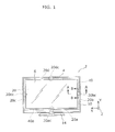
- FIG. 1 illustrates the display apparatus from the front.
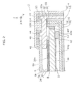
- FIG. 2 is a cross section showing the relevant components in the display apparatus at the line A-A shown in FIG. 1 .
- the display apparatus 2 includes a housing 4, a liquid crystal panel 6 (which includes the display panel) provided in the housing 4, and a backlight unit 8 provided in the housing 4.
- the display apparatus 2 according to Embodiment 1 is a liquid crystal television receiver equipped with the edge-lit backlight unit 8.
- the backlight unit 8 is not limited to an edge-lit type backlight unit.
- a front cabinet 10 and a rear cabinet 12 are put together to form the housing 4.
- the front cabinet 10 is formed in the shape of a frame and covers the outer peripheral portion of the liquid crystal panel 6.
- the rear cabinet 12 is arranged facing the back surface 6a of the liquid crystal panel 6.
- the rear cabinet 12 includes a rectangular opening 12a to accommodate the liquid crystal panel 6.
- a stand 14 for supporting the housing 4 from below is attached to the bottom end portion of the rear cabinet 12.
- the backlight unit 8 is supported by the internal surface side of the rear cabinet 12.
- the backlight unit 8 is for emitting light toward the back surface 6a of the liquid crystal panel 6.
- the backlight unit 8 includes a heat sink 16, an LED bar 18, a light guide plate 20, a reflective sheet 22, and an optical sheet 24.
- the heat sink 16 includes a flat heat dissipation portion 26 and an attachment portion 28 which extends substantially vertical from one end portion of the heat dissipation portion 26 toward the liquid crystal panel 6.
- the heat sink 16 has a cross section that is substantially L-shaped.
- the heat dissipation portion 26 is attached to the internal surface side of the rear cabinet 12 with screws (not shown in the drawings).
- the attachment portion 28 positionally corresponds to, among four peripheral edge portions 20a through 20d of the light guide plate 20, the peripheral edge portion 20b, which extends in the lengthwise direction of the short side.
- the heat sink 16 is made from a metal having high thermal conductivity, such as aluminum.
- the LED bar 18 includes a wiring substrate 30 and a plurality of LEDs 32 (The plurality of LEDs 32 constitute a light source).
- the wiring substrate 30 has an elongated plate-like shape.
- the LEDs 32 are arranged in a line in the longitudinal direction of the wiring substrate 30 and spaced apart from each other.
- the plurality of LEDs 33 are each, for example, chip-type LEDs.
- the wiring substrate 30 is attached to the attachment portion 28 of the heat sink 16 with double sided tape (not shown in the drawings) having heat transfer properties. It should be noted that the wiring substrate 30 is made from a metal having high thermal conductivity, such as aluminum.
- the light guide plate 20 is rectangular and supported by the heat dissipation portion 26 of the heat sink 16 via a cushion 34 formed from, for example, a rubber material. It should be noted that the cushion 34 positionally corresponds to the outer peripheral portion of the light guide plate 20.
- a main surface 20e of the light guide plate 20 is arranged to face the back surface 6a of the liquid crystal panel 6.
- a side surface 20f of the light guide plate 20 is arranged to face the plurality of LEDs 32.
- the light guide plate 20 is made from, for example, acrylic resin.
- the reflective sheet 22 is arranged so as to cover the back surface 20g of the light guide plate 20 (in other words, arranged to cover the surface on the opposite side of the main surface 20e).
- the reflective sheet 22 has an optical function of reflecting, toward the main surface 20e, light entering from the side surface 20f of the light guide plate 20.
- the optical sheet 24 includes a diffusion sheet 36 and a lens sheet 38.
- the diffusion sheet 36 and the lens sheet 38, while mutually superimposed, are arranged so as to cover the main surface 20e of the light guide plate 20.
- the diffusion sheet 36 has an optical function of diffusing light exiting from the main surface 20e of the light guide plate 20.
- the lens sheet 38 has an optical function of guiding the light diffused by the diffusion sheet 36 toward the back surface 6a of the liquid crystal panel 6.
- a molded frame 40 for supporting the four peripheral edge portions of the liquid crystal panel 6 via the back surface 6a of the liquid crystal panel 6 is attached to the opening 12a of the rear cabinet 12 with screws (not shown in the drawings).
- the molded frame 40 is frame-shaped.
- the back surface of the molded frame 40 (in other words, the surface of the molded frame 40 on the light guide plate 20 side) is provided with a first rib portion 42
- the front surface of the molded frame 40 (in other words, the surface of the molded frame 40 on the liquid crystal panel 6 side) is provided with a second rib portion 44.
- the first rib portion 42 protrudes toward the main surface 20e of the light guide plate 20.
- the first rib portion 42 is provided to form a gap 46 between the molded frame 40 and the four peripheral edge portions 20a through 20d of the light guide plate 20.
- the four peripheral edge portions of both the diffusion sheet 36 and the lens sheet 38 are arranged in the gap 46.
- the first rib portion 42 is in continuous contact with the main surface 20e of the light guide plate 20 along the three peripheral edge portions 20b through 20d.
- the first rib portion 42 (which is included in the rib portion) is in discontinuous contact with the main surface 20e of the light guide plate 20 along the peripheral edge portion 20a of the light guide plate 20.
- the second rib portion 44 protrudes toward a bezel 50 (to be described later).
- the second rib portion 44 is provided to form a gap 48 between the molded frame 40 and the bezel 50.
- Four peripheral edge portions of the liquid crystal panel 6 are arranged in the gap 48.
- the liquid crystal panel 6 is rectangular and the four peripheral edge portions thereof are supported by the inner peripheral portion (the portion of the molded frame 40 inward relative to the second rib portion 44) of the molded frame 40.
- Light from the backlight unit 8 shines on the back surface 6a of the liquid crystal panel 6 whereby an image is displayed on the liquid crystal panel 6.
- the four peripheral edge portions on the front surface 6b (in other words, the surface of the liquid crystal panel 6 on the opposite side of the back surface 6a) of the liquid crystal panel 6 are covered by the bezel 50.
- the bezel 50 has the shape of, for example, a frame, and is fixed to the molded frame 40 by screws (not shown in the drawings). This sandwiches the four peripheral edge portions of the liquid crystal panel 6 between the bezel 50 and the molded frame 40.
- front cabinet 10 is attached to the rear cabinet 12 by screws (not shown in the drawings) so that the front cabinet 10 covers the bezel 50 and the molded frame 40.
- the attachment structure of the front cabinet 10 and the bezel 50 will be described with reference to FIG. 3 and FIG. 4 .
- the liquid crystal panel 6, the bezel 50, and the molded frame 40 are collectively referred to as a "display module”.
- FIG. 3 is an illustration of the front cabinet 10 as seen from the back, at a center region 20bc located approximately in the center of the peripheral edge portion 20b illustrated in FIG. 1 in the lengthwise direction thereof.
- FIG. 4 is a cross section of the front cabinet 10 and the bezel 50 at the line B-B shown in FIG. 1 or the line C-C shown in FIG. 3 .
- the front cabinet 10 includes a rib member 13A (first protrusion) that protrudes toward the display module.
- the rib member 13A includes a rib 10A that extends in the lengthwise direction of the short sides of the front cabinet 10 (Y axis direction) and a rib 10B that extends in the lengthwise direction of the long sides of the front cabinet 10 (X axis direction).
- a hole 11A that accommodates the rib member 13A is formed on the bezel 50 across from the rib member 13A.
- the hole 11A has, for example, a circular shape.
- the width of the rib 10A in the Y axis direction and the width of the hole 11A in the Y axis direction are substantially equal. As such, movement of the front cabinet 10 in the Y axis direction is restricted by the hole 11A. Conversely, as is illustrated in FIG. 3 and FIG. 2 , the width of the rib 10B in the X axis direction is narrower than the width of the hole 11A in the X axis direction. This allows for play, of the front cabinet 10, in the X axis direction. In other words, the front cabinet 10 can move to a certain degree in the X axis direction at the center region 20bc. It should be noted that the rib 10B is provided in the rib member 13A to reinforce the rib 10A, but provision of thereof in the rib member 13A is not absolutely necessary.
- the front cabinet 10 and the bezel 50 also have the same configuration illustrated in FIG. 3 at a center region 20cc located approximately in the center of the peripheral edge portion 20c illustrated in FIG. 1 in the lengthwise direction thereof as well.
- a rib member 13B is formed on the front cabinet 10 at a center region 20ac located approximately in the center of the peripheral edge portion 20a illustrated in FIG. 1 in the lengthwise direction thereof as well as at a center region 20dc located approximately in the center of the peripheral edge portion 20d illustrated in FIG. 1 in the lengthwise direction thereof.
- the hole 11A that accommodates the rib member 13B is formed on the bezel 50 across from the rib member 13B.
- the rib member 13B includes the rib 10A that extends in the X axis direction and the rib 10B that extends in the Y axis direction.
- the width of the rib 10A in the X axis direction and the width of the hole 11A in the X axis direction are substantially equal. As such, movement of the front cabinet 10 in the X axis direction is restricted by the hole 11A. Conversely, the width of the rib 10B in the Y axis direction is narrower than the width of the hole 11A in the Y axis direction. This allows for play, of the front cabinet 10, in the Y axis direction. In other words, the front cabinet 10 can move to a certain degree in the Y axis direction at the center region 20ac and the center region 20dc.
- the front cabinet 10 and/or the display module thermally expands or contracts, since they expand or contract in a direction from the rib member 13A and/or the rib member 13B toward the corner regions, the areas around the rib member 13A and the rib member 13B are resistant to influence from expansion and contraction, and similarly resistant to influence from variations in size. This makes it possible to secure the display module to the front cabinet 10 in a manner that is insusceptible to heat or variations in size.
- the rib members 13A arranged in the center region 20bc and the center region 20cc do not restrict movement in the X axis direction. As such, even if the front cabinet 10 and/or the display module thermally expand or contract in the X axis direction or there are variations in size in the X axis direction, a large force is not applied to the rib members 13A.
- the rib members 13B arranged in the center region 20ac and the center region 20dc do not restrict movement in the Y axis direction. As such, even if the front cabinet 10 and/or the display module thermally expand or contract in the Y axis direction or there are variations in size in the Y axis direction, a large force is not applied to the rib members 13B.
- the bezel 50 in the display apparatus according to Embodiment 2 is provided with a different shaped hole than Embodiment 1. All other constituent elements are the same as in Embodiment 1.
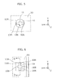
- FIG. 6 is an illustration of the front cabinet 10 as seen from the back, at the center region 20bc illustrated in FIG. 1 .
- the front cabinet 10 is provided with the same rib member 13A as in Embodiment 1.
- a hole 11B that accommodates the rib member 13A is formed on the bezel 50 across from the rib member 13A.
- the hole 11B has, for example, a quadrilateral shape.
- the width of the rib 10A in the Y axis direction and the width of the hole 11B in the Y axis direction are substantially equal. As such, movement of the front cabinet 10 in the Y axis direction is restricted by the hole 11B. Conversely, as is illustrated in FIG. 3 and FIG. 2 , the width of the rib 10B in the X axis direction is narrower than the width of the hole 11B in the X axis direction. This allows for play, of the front cabinet 10, in the X axis direction.
- front cabinet 10 and the bezel 50 also have the same configuration illustrated in FIG. 6 at the center region 20cc as well.
- the front cabinet 10 and the bezel 50 are configured to use the hole 11B as a substitute for the hole 11A shown in FIG. 5 .
- Embodiment 2 has the same advantageous effects as Embodiment 1.
- the bezel 50 is provided with the holes.
- Embodiment 3 a variation of the display apparatus in which the molded frame 40 is provided with a recess will be described.
- FIG. 7 is a cross section showing the relevant components in the display apparatus 2 at the line B-B shown in FIG. 1 .
- the cross section illustrated only includes the front cabinet 10, the bezel 50, and the molded frame 40.
- FIG. 8 is a cross section showing the relevant components in the display apparatus 2 at the line A-A shown in FIG. 1 .
- the cross section illustrated only includes the front cabinet 10, the bezel 50, and the molded frame 40.
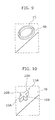
- FIG. 9 illustrates the molded frame 40 as seen from the front of the display apparatus 2, at the center region 20bc.
- FIG. 10 is an illustration of the front cabinet 10 as seen from the back of the display apparatus 2, at the center region 20bc.
- the front cabinet 10 is provided with the same rib member 13A as in Embodiments 1 and 2.
- a circular recess 15 that accommodates the rib member 13A is formed on the molded frame 40 across from the rib member 13A.
- the width of the rib 10A in the Y axis direction and the width of the recess 15 in the Y axis direction are substantially equal. As such, movement of the front cabinet 10 in the Y axis direction is restricted by the recess 15. Conversely, as is illustrated in FIG. 8 through FIG. 10 , the width of the rib 10B in the X axis direction is narrower than the width of the recess 15 in the X axis direction. This allows for play, of the front cabinet 10, in the X axis direction. In other words, the front cabinet 10 can move to a certain degree in the X axis direction at the center region 20bc.
- the front cabinet 10 and the molded frame 40 also have the same configuration illustrated in FIG. 7 through FIG. 10 at the center region 20cc illustrated in FIG. 1 as well.
- the front cabinet 10 and the molded frame 40 also have the same configuration illustrated in FIG. 7 through FIG. 10 at the center region 20ac and the center region 20dc illustrated in FIG. 1 as well.
- the orientations of the rib 10A and the rib 10B are different. More specifically, the rib 10A is formed so that the lengthwise direction thereof is parallel to the X axis direction and the rib 10B is formed so that the lengthwise direction thereof is parallel to the Y axis direction.
- the front cabinet 10 in the X axis direction is restricted, and room for play of the front cabinet 10 in the Y axis direction is provided.
- Embodiment 3 has the same advantageous effects as Embodiment 1.
- the front cabinet 10 is provided with rib members, and the molded frame 40 is provided with recesses.
- the molded frame 40 is provided with rib members and the front cabinet 10 is provided with recesses will be discussed.
- FIG. 11 is a cross section showing the relevant components in the display apparatus 2 at the line B-B shown in FIG. 1 .
- the cross section illustrated only includes the front cabinet 10, the bezel 50, and the molded frame 40.
- FIG. 12 is a cross section showing the relevant components in the display apparatus 2 at the line A-A shown in FIG. 1 .
- the cross section illustrated only includes the front cabinet 10, the bezel 50, and the molded frame 40.
- FIG. 13 is an illustration of the front cabinet 10 as seen from the back of the display apparatus 2, at the center region 20bc.
- FIG. 14 illustrates the molded frame 40 as seen from the front of the display apparatus 2, at the center region 20bc.
- the front cabinet 10 is provided with a cylindrical recess 19.
- a rib member 17 that fits into the recess 19 is formed on the molded frame 40.
- the rib member 17 includes a rib 17A that extends in the Y axis direction and a rib 17B that extends in the X axis direction.
- the width of the rib 17A in the Y axis direction and the width of the recess 19 in the Y axis direction are substantially equal. As such, movement of the front cabinet 10 in the Y axis direction is restricted by the rib member 17. Conversely, as is illustrated in FIG. 12 through FIG. 14 , the width of the rib 17B in the X axis direction is narrower than the width of the recess 19 in the X axis direction. This allows for play, of the front cabinet 10, in the X axis direction. In other words, the front cabinet 10 can move to a certain degree in the X axis direction at the center region 20bc.
- the front cabinet 10 and the molded frame 40 also have the same configuration illustrated in FIG. 11 through FIG. 14 at the center region 20cc illustrated in FIG. 1 as well.
- the front cabinet 10 and the molded frame 40 also have the same configuration illustrated in FIG. 11 through FIG. 14 at the center region 20ac and the center region 20dc illustrated in FIG. 1 as well.
- the orientations of the rib 17A and the rib 17B are different. More specifically, the rib 17A is formed so that the lengthwise direction thereof is parallel to the X axis direction and the rib 17B is formed so that the lengthwise direction thereof is parallel to the Y axis direction.
- the front cabinet 10 in the X axis direction is restricted, and room for play of the front cabinet 10 in the Y axis direction is provided.
- Embodiment 4 has the same advantageous effects as Embodiment 1.
- the display apparatus has hereinbefore been described according to the embodiments of the present invention, but the present invention is not limited to these embodiments.
- rib members and holes or recesses are provided at the center regions 20ac, 20bc, 20cc, and 20dd to restrict movement of the molded frame 40, but the locations of the rib members etc. are not limited to these locations; they may be located at other regions except for the corner regions of the front cabinet 10.
- the rib members etc. provided on the peripheral edge portion 20a and the peripheral edge portion 20d are preferably provided the same distance from one end of the peripheral edge portion 20a and the peripheral edge portion 20d.
- the rib members etc. provided on the peripheral edge portion 20b and the peripheral edge portion 20c are preferably provided the same distance from one end of the peripheral edge portion 20b and the peripheral edge portion 20c.
- the shape of the recess described in Embodiments 3 and 4 is not limited to a cylindrical shape, and may be rectangular. Moreover, a hole may be provided in the molded frame 40 or the front cabinet 10 instead of the recess.
- the present invention is applicable as a playback device such as a television that reproduces a television broadcast.
Landscapes
- Physics & Mathematics (AREA)
- Nonlinear Science (AREA)
- Mathematical Physics (AREA)
- Chemical & Material Sciences (AREA)
- Crystallography & Structural Chemistry (AREA)
- General Physics & Mathematics (AREA)
- Optics & Photonics (AREA)
- Engineering & Computer Science (AREA)
- Microelectronics & Electronic Packaging (AREA)
- Devices For Indicating Variable Information By Combining Individual Elements (AREA)
- Liquid Crystal (AREA)
Abstract
Description
- The present invention relates to display apparatuses for displaying images.
- Display apparatuses that display images on a display panel, such as a liquid crystal television receiver, are conventionally known (for example, see Patent Literature (PTL) 1).
- In such a conventional display apparatus, the display module and the front cabinet are kept from becoming misaligned by fixing the display module, including the display panel, and the front cabinet. By keeping the display module and the front cabinet from becoming misaligned, the problem of screen obstruction can be solved. Here, "screen obstruction" refers to an edge portion of the display panel becoming covered by the front cabinet as a result of the display panel and the front cabinet becoming misaligned, whereby a portion of the image displayed in the edge portion of the display panel becomes out of view.
- [PTL 1] Japanese Unexamined Patent Application Publication No.
2000-181371 - In PTL 1, the front cabinet and the display module are fastened together by screws at the corner regions of the front cabinet. As such, when the front cabinet or the display module thermally expand and contract, this applies a large force to the portions where the screws are provided, and as a result, there is a problem that the screws or the areas around the screws on the front cabinet or the display module break. There are also instances when a large force is applied to the front cabinet or the display module due to variations in size of the front cabinet or the display module.
- The present invention was conceived to solve the above-described problem and aims to provide a display apparatus that is capable of securing the display module to the front cabinet in a manner that is insusceptible to heat or variations in size.
- In order to achieve the above goal, one aspect of the display apparatus includes: a display module including a display panel; and a front cabinet that covers an outer peripheral portion of the display module from a front side of the display module, wherein the front cabinet includes on each long side thereof a first protrusion at a location other than a corner region of the front cabinet, the first protrusion protruding toward the display module, the front cabinet includes on each short side thereof a second protrusion at a location other than the corner region of the front cabinet, the second protrusion protruding toward the display module, and the display module includes a first restrictor across from the first protrusion and a second restrictor across from the second protrusion, the first restrictor restricting movement of the first protrusion in a lengthwise direction of the long side of the front cabinet and the second restrictor restricting movement of the second protrusion in a lengthwise direction of the short side of the front cabinet.
- With this configuration, movement of the display module with respect to the front cabinet is restricted except for in positions at the corner regions of the front cabinet. As such, even if the front cabinet and/or the display module thermally expands or contracts, since they expand or contract in a direction from the protrusion toward the corner regions, the areas around the first protrusion and the second protrusion are resistant to influence from expansion and contraction, and similarly resistant to influence from variations in size. This makes it possible to secure the display module to the front cabinet in a manner that is insusceptible to heat or variations in size.
- For example, the first protrusion may include a first rib, and the first restrictor may include a first hole that accommodates the first rib and is of a size that restricts movement of the first rib in the lengthwise direction of the long side of the front cabinet and allows for play of the first rib in the lengthwise direction of the short side of the front cabinet.
- With this configuration, movement of the first ribs provided on the long sides of the front cabinet is restricted in the lengthwise direction of the long sides of the front cabinet, but not restricted in the lengthwise direction of the short sides of the front cabinet. As such, even if the front cabinet and/or the display module thermally expand or contract in the lengthwise direction of the short sides or there are variations in size in the lengthwise direction of the short sides, a large force is not applied to the first ribs.
- Moreover, the second protrusion may include a second rib, and the second restrictor may include a second hole that accommodates the second rib and is of a size that restricts movement of the second rib in the lengthwise direction of the short side of the front cabinet and allows for play of the second rib in the lengthwise direction of the long side of the front cabinet.
- With this configuration, movement of the second ribs provided on the short sides of the front cabinet is restricted in the lengthwise direction of the short sides of the front cabinet, but not restricted in the lengthwise direction of the long sides of the front cabinet. As such, even if the front cabinet and/or the display module thermally expand or contract in the lengthwise direction of the long sides or there are variations in size in the lengthwise direction of the long sides, a large force is not applied to the second ribs.
- Moreover, the first protrusion may include a first rib, and the first restrictor may include a first recess that accommodates the first rib and is of a size that restricts movement of the first rib in the lengthwise direction of the long side of the front cabinet and allows for play of the first rib in the lengthwise direction of the short side of the front cabinet.
- With this configuration, movement of the first ribs provided on the long sides of the front cabinet is restricted in the lengthwise direction of the long sides of the front cabinet, but not restricted in the lengthwise direction of the short sides of the front cabinet. As such, even if the front cabinet and/or the display module thermally expand or contract in the lengthwise direction of the short sides or there are variations in size in the lengthwise direction of the short sides, a large force is not applied to the first ribs.
- Moreover, the second protrusion may include a second rib, and the second restrictor may include a second recess that accommodates the second rib and is of a size that restricts movement of the second rib in the lengthwise direction of the short side of the front cabinet and allows for play of the second rib in the lengthwise direction of the long side of the front cabinet.
- With this configuration, movement of the second ribs provided on the short sides of the front cabinet is restricted in the lengthwise direction of the short sides of the front cabinet, but not restricted in the lengthwise direction of the long sides of the front cabinet. As such, even if the front cabinet and/or the display module thermally expand or contract in the lengthwise direction of the long sides or there are variations in size in the lengthwise direction of the long sides, a large force is not applied to the second ribs.
- Moreover, the first protrusion may include a first recess, and the first restrictor may include a first rib that fits in the first recess and is of a size that restricts movement of the first recess in the lengthwise direction of the long side of the front cabinet and allows for play of the first recess in the lengthwise direction of the short side of the front cabinet.
- With this configuration, movement of the first recesses provided on the long sides of the front cabinet is restricted in the lengthwise direction of the long sides of the front cabinet, but not restricted in the lengthwise direction of the short sides of the front cabinet. As such, even if the front cabinet and/or the display module thermally expand or contract in the lengthwise direction of the short sides or there are variations in size in the lengthwise direction of the short sides, a large force is not applied to the first recesses.
- Moreover, the second protrusion may include a second recess, and the second restrictor may include a second rib that fits in the second recess and is of a size that restricts movement of the second recess in the lengthwise direction of the short side of the front cabinet and allows for play of the second recess in the lengthwise direction of the long side of the front cabinet.
- With this configuration, movement of the second recesses provided on the short sides of the front cabinet is restricted in the lengthwise direction of the short sides of the front cabinet, but not restricted in the lengthwise direction of the long sides of the front cabinet. As such, even if the front cabinet and/or the display module thermally expand or contract in the lengthwise direction of the long sides or there are variations in size in the lengthwise direction of the long sides, a large force is not applied to the second recesses.
- Moreover, the first protrusions may be located a same distance from an end of the long sides of the front cabinet, and the second protrusions may be located a same distance from an end of the short sides of the front cabinet.
- With this configuration, when force is applied to the protrusions, equal force is applied to the two first protrusions, and equal force is applied to the two second protrusions.
- Moreover, the first protrusion may be located at a center of the long side of the front cabinet in a lengthwise direction, and the second protrusion may be located at a center of the short side of the front cabinet in a lengthwise direction.
- With the present invention, it is possible to provide a display apparatus that is capable of securing the display module to the front cabinet in a manner that is insusceptible to heat or variations in size.
-
- [
FIG. 1] FIG. 1 illustrates the display apparatus from the front. - [
FIG. 2] FIG. 2 is a cross section illustrating the relevant components in the display apparatus at the line A-A shown inFIG. 1 . - [
FIG. 3] FIG. 3 is an illustration of the front cabinet as seen from the back. - [
FIG. 4] FIG. 4 is a cross section of the front cabinet and the bezel at the line B-B shown inFIG. 1 or the line C-C shown inFIG. 3 . - [
FIG. 5] FIG. 5 is an illustration of the front cabinet as seen from the back. - [
FIG. 6] FIG. 6 is an illustration of the front cabinet as seen from the back. - [
FIG. 7] FIG. 7 is a cross section showing the relevant components in the display apparatus at the line B-B shown inFIG. 1 . - [
FIG. 8] FIG. 8 is a cross section showing the relevant components in the display apparatus at the line A-A shown inFIG. 1 . - [
FIG. 9] FIG. 9 illustrates the molded frame as seen from the front of the display apparatus. - [
FIG. 10] FIG. 10 is an illustration of the front cabinet as seen from the back of the display apparatus. - [
FIG. 11] FIG. 11 is a cross section showing the relevant components in the display apparatus at the line B-B shown inFIG. 1 . - [
FIG. 12] FIG. 12 is a cross section showing the relevant components in the display apparatus at the line A-A shown inFIG. 1 . - [
FIG. 13] FIG. 13 is an illustration of the front cabinet as seen from the back of the display apparatus. - [
FIG. 14] FIG. 14 illustrates the molded frame as seen from the front of the display apparatus. - Hereinafter, certain exemplary embodiments are described in greater detail with reference to the accompanying Drawings. It should be noted the embodiments described below show specific examples of the present invention. The numerical values, shapes, materials, structural elements, the arrangement and connection of the structural elements etc. shown in the following exemplary embodiments are mere examples, and therefore do not limit the present invention, the scope of which is defined in the appended Claims. As such, among the structural elements in the following exemplary embodiments, structural elements not recited in any one of the independent claims defining the most generic part of the inventive concept are described as structural elements of a preferable embodiment, and are not absolutely necessary to overcome the problem according to the present invention.
- First, the overall configuration of the display apparatus according to Embodiment 1 is described with reference to
FIG. 1 andFIG. 2 .FIG. 1 illustrates the display apparatus from the front.FIG. 2 is a cross section showing the relevant components in the display apparatus at the line A-A shown inFIG. 1 . - As is illustrated in
FIG. 1 andFIG. 2 , thedisplay apparatus 2 includes ahousing 4, a liquid crystal panel 6 (which includes the display panel) provided in thehousing 4, and a backlight unit 8 provided in thehousing 4. Thedisplay apparatus 2 according to Embodiment 1 is a liquid crystal television receiver equipped with the edge-lit backlight unit 8. However, the backlight unit 8 is not limited to an edge-lit type backlight unit. - A
front cabinet 10 and arear cabinet 12 are put together to form thehousing 4. Thefront cabinet 10 is formed in the shape of a frame and covers the outer peripheral portion of theliquid crystal panel 6. Therear cabinet 12 is arranged facing theback surface 6a of theliquid crystal panel 6. Therear cabinet 12 includes arectangular opening 12a to accommodate theliquid crystal panel 6. Astand 14 for supporting thehousing 4 from below is attached to the bottom end portion of therear cabinet 12. - The backlight unit 8 is supported by the internal surface side of the
rear cabinet 12. The backlight unit 8 is for emitting light toward theback surface 6a of theliquid crystal panel 6. The backlight unit 8 includes aheat sink 16, anLED bar 18, alight guide plate 20, areflective sheet 22, and anoptical sheet 24. - The
heat sink 16 includes a flatheat dissipation portion 26 and anattachment portion 28 which extends substantially vertical from one end portion of theheat dissipation portion 26 toward theliquid crystal panel 6. In other words, theheat sink 16 has a cross section that is substantially L-shaped. Theheat dissipation portion 26 is attached to the internal surface side of therear cabinet 12 with screws (not shown in the drawings). Theattachment portion 28 positionally corresponds to, among fourperipheral edge portions 20a through 20d of thelight guide plate 20, theperipheral edge portion 20b, which extends in the lengthwise direction of the short side. It should be noted that theheat sink 16 is made from a metal having high thermal conductivity, such as aluminum. - The
LED bar 18 includes awiring substrate 30 and a plurality of LEDs 32 (The plurality ofLEDs 32 constitute a light source). Thewiring substrate 30 has an elongated plate-like shape. TheLEDs 32 are arranged in a line in the longitudinal direction of thewiring substrate 30 and spaced apart from each other. The plurality of LEDs 33 are each, for example, chip-type LEDs. Thewiring substrate 30 is attached to theattachment portion 28 of theheat sink 16 with double sided tape (not shown in the drawings) having heat transfer properties. It should be noted that thewiring substrate 30 is made from a metal having high thermal conductivity, such as aluminum. - The
light guide plate 20 is rectangular and supported by theheat dissipation portion 26 of theheat sink 16 via acushion 34 formed from, for example, a rubber material. It should be noted that thecushion 34 positionally corresponds to the outer peripheral portion of thelight guide plate 20. Amain surface 20e of thelight guide plate 20 is arranged to face theback surface 6a of theliquid crystal panel 6. Aside surface 20f of thelight guide plate 20 is arranged to face the plurality ofLEDs 32. It should be noted that thelight guide plate 20 is made from, for example, acrylic resin. - The
reflective sheet 22 is arranged so as to cover theback surface 20g of the light guide plate 20 (in other words, arranged to cover the surface on the opposite side of themain surface 20e). Thereflective sheet 22 has an optical function of reflecting, toward themain surface 20e, light entering from theside surface 20f of thelight guide plate 20. - The
optical sheet 24 includes adiffusion sheet 36 and alens sheet 38. Thediffusion sheet 36 and thelens sheet 38, while mutually superimposed, are arranged so as to cover themain surface 20e of thelight guide plate 20. Thediffusion sheet 36 has an optical function of diffusing light exiting from themain surface 20e of thelight guide plate 20. Thelens sheet 38 has an optical function of guiding the light diffused by thediffusion sheet 36 toward theback surface 6a of theliquid crystal panel 6. - A molded
frame 40 for supporting the four peripheral edge portions of theliquid crystal panel 6 via theback surface 6a of theliquid crystal panel 6 is attached to theopening 12a of therear cabinet 12 with screws (not shown in the drawings). In Embodiment 1, the moldedframe 40 is frame-shaped. The back surface of the molded frame 40 (in other words, the surface of the moldedframe 40 on thelight guide plate 20 side) is provided with afirst rib portion 42, and the front surface of the molded frame 40 (in other words, the surface of the moldedframe 40 on theliquid crystal panel 6 side) is provided with asecond rib portion 44. - The
first rib portion 42 protrudes toward themain surface 20e of thelight guide plate 20. Thefirst rib portion 42 is provided to form agap 46 between the moldedframe 40 and the fourperipheral edge portions 20a through 20d of thelight guide plate 20. The four peripheral edge portions of both thediffusion sheet 36 and thelens sheet 38 are arranged in thegap 46. In Embodiment 1, at the portions of the moldedframe 40 corresponding to the threeperipheral edge portions 20b through 20d of thelight guide plate 20, thefirst rib portion 42 is in continuous contact with themain surface 20e of thelight guide plate 20 along the threeperipheral edge portions 20b through 20d. Moreover, at theportion 40a (hereinafter referred to as thesupport member 40a) of the moldedframe 40 that corresponds to theperipheral edge portion 20a of thelight guide plate 20 closest to thestand 14, the first rib portion 42 (which is included in the rib portion) is in discontinuous contact with themain surface 20e of thelight guide plate 20 along theperipheral edge portion 20a of thelight guide plate 20. A more specific description of the configuration of thefirst rib portion 42 provided on thesupport member 40a will be given later. - The
second rib portion 44 protrudes toward a bezel 50 (to be described later). Thesecond rib portion 44 is provided to form agap 48 between the moldedframe 40 and thebezel 50. Four peripheral edge portions of theliquid crystal panel 6 are arranged in thegap 48. - The
liquid crystal panel 6 is rectangular and the four peripheral edge portions thereof are supported by the inner peripheral portion (the portion of the moldedframe 40 inward relative to the second rib portion 44) of the moldedframe 40. Light from the backlight unit 8 shines on theback surface 6a of theliquid crystal panel 6 whereby an image is displayed on theliquid crystal panel 6. The four peripheral edge portions on thefront surface 6b (in other words, the surface of theliquid crystal panel 6 on the opposite side of theback surface 6a) of theliquid crystal panel 6 are covered by thebezel 50. Thebezel 50 has the shape of, for example, a frame, and is fixed to the moldedframe 40 by screws (not shown in the drawings). This sandwiches the four peripheral edge portions of theliquid crystal panel 6 between thebezel 50 and the moldedframe 40. - It should be noted that the
front cabinet 10 is attached to therear cabinet 12 by screws (not shown in the drawings) so that thefront cabinet 10 covers thebezel 50 and the moldedframe 40. - Next, the attachment structure of the
front cabinet 10 and thebezel 50 will be described with reference toFIG. 3 and FIG. 4 . In the following description, theliquid crystal panel 6, thebezel 50, and the moldedframe 40 are collectively referred to as a "display module". -
FIG. 3 is an illustration of thefront cabinet 10 as seen from the back, at a center region 20bc located approximately in the center of theperipheral edge portion 20b illustrated inFIG. 1 in the lengthwise direction thereof.FIG. 4 is a cross section of thefront cabinet 10 and thebezel 50 at the line B-B shown inFIG. 1 or the line C-C shown inFIG. 3 . - The
front cabinet 10 includes arib member 13A (first protrusion) that protrudes toward the display module. Therib member 13A includes arib 10A that extends in the lengthwise direction of the short sides of the front cabinet 10 (Y axis direction) and arib 10B that extends in the lengthwise direction of the long sides of the front cabinet 10 (X axis direction). Ahole 11A that accommodates therib member 13A is formed on thebezel 50 across from therib member 13A. Thehole 11A has, for example, a circular shape. - As is illustrated in
FIG. 3 and FIG. 4 , the width of therib 10A in the Y axis direction and the width of thehole 11A in the Y axis direction are substantially equal. As such, movement of thefront cabinet 10 in the Y axis direction is restricted by thehole 11A. Conversely, as is illustrated inFIG. 3 andFIG. 2 , the width of therib 10B in the X axis direction is narrower than the width of thehole 11A in the X axis direction. This allows for play, of thefront cabinet 10, in the X axis direction. In other words, thefront cabinet 10 can move to a certain degree in the X axis direction at the center region 20bc. It should be noted that therib 10B is provided in therib member 13A to reinforce therib 10A, but provision of thereof in therib member 13A is not absolutely necessary. - The
front cabinet 10 and thebezel 50 also have the same configuration illustrated inFIG. 3 at a center region 20cc located approximately in the center of theperipheral edge portion 20c illustrated inFIG. 1 in the lengthwise direction thereof as well. - Moreover, as is illustrated in
FIG. 5 , arib member 13B is formed on thefront cabinet 10 at a center region 20ac located approximately in the center of theperipheral edge portion 20a illustrated inFIG. 1 in the lengthwise direction thereof as well as at a center region 20dc located approximately in the center of theperipheral edge portion 20d illustrated inFIG. 1 in the lengthwise direction thereof. Moreover, thehole 11A that accommodates therib member 13B is formed on thebezel 50 across from therib member 13B. Therib member 13B includes therib 10A that extends in the X axis direction and therib 10B that extends in the Y axis direction. The width of therib 10A in the X axis direction and the width of thehole 11A in the X axis direction are substantially equal. As such, movement of thefront cabinet 10 in the X axis direction is restricted by thehole 11A. Conversely, the width of therib 10B in the Y axis direction is narrower than the width of thehole 11A in the Y axis direction. This allows for play, of thefront cabinet 10, in the Y axis direction. In other words, thefront cabinet 10 can move to a certain degree in the Y axis direction at the center region 20ac and the center region 20dc. - As described above, movement of the display module with respect to the
front cabinet 10 is restricted except for in positions at the corner regions of thefront cabinet 10. As such, even if thefront cabinet 10 and/or the display module thermally expands or contracts, since they expand or contract in a direction from therib member 13A and/or therib member 13B toward the corner regions, the areas around therib member 13A and therib member 13B are resistant to influence from expansion and contraction, and similarly resistant to influence from variations in size. This makes it possible to secure the display module to thefront cabinet 10 in a manner that is insusceptible to heat or variations in size. - It should be noted that the
rib members 13A arranged in the center region 20bc and the center region 20cc do not restrict movement in the X axis direction. As such, even if thefront cabinet 10 and/or the display module thermally expand or contract in the X axis direction or there are variations in size in the X axis direction, a large force is not applied to therib members 13A. - Likewise, the
rib members 13B arranged in the center region 20ac and the center region 20dc do not restrict movement in the Y axis direction. As such, even if thefront cabinet 10 and/or the display module thermally expand or contract in the Y axis direction or there are variations in size in the Y axis direction, a large force is not applied to therib members 13B. - The
bezel 50 in the display apparatus according toEmbodiment 2 is provided with a different shaped hole than Embodiment 1. All other constituent elements are the same as in Embodiment 1. -
FIG. 6 is an illustration of thefront cabinet 10 as seen from the back, at the center region 20bc illustrated inFIG. 1 . - The
front cabinet 10 is provided with thesame rib member 13A as in Embodiment 1. Ahole 11B that accommodates therib member 13A is formed on thebezel 50 across from therib member 13A. Thehole 11B has, for example, a quadrilateral shape. - The width of the
rib 10A in the Y axis direction and the width of thehole 11B in the Y axis direction are substantially equal. As such, movement of thefront cabinet 10 in the Y axis direction is restricted by thehole 11B. Conversely, as is illustrated inFIG. 3 andFIG. 2 , the width of therib 10B in the X axis direction is narrower than the width of thehole 11B in the X axis direction. This allows for play, of thefront cabinet 10, in the X axis direction. - It should be noted that the
front cabinet 10 and thebezel 50 also have the same configuration illustrated inFIG. 6 at the center region 20cc as well. - Moreover, at the center region 20ac and the center region 20dc, the
front cabinet 10 and thebezel 50 are configured to use thehole 11B as a substitute for thehole 11A shown inFIG. 5 . - With this,
Embodiment 2 has the same advantageous effects as Embodiment 1. - In
Embodiments 1 and 2, thebezel 50 is provided with the holes. In Embodiment 3, a variation of the display apparatus in which the moldedframe 40 is provided with a recess will be described. -
FIG. 7 is a cross section showing the relevant components in thedisplay apparatus 2 at the line B-B shown inFIG. 1 . The cross section illustrated only includes thefront cabinet 10, thebezel 50, and the moldedframe 40.FIG. 8 is a cross section showing the relevant components in thedisplay apparatus 2 at the line A-A shown inFIG. 1 . The cross section illustrated only includes thefront cabinet 10, thebezel 50, and the moldedframe 40.FIG. 9 illustrates the moldedframe 40 as seen from the front of thedisplay apparatus 2, at the center region 20bc.FIG. 10 is an illustration of thefront cabinet 10 as seen from the back of thedisplay apparatus 2, at the center region 20bc. - As is illustrated, the
front cabinet 10 is provided with thesame rib member 13A as inEmbodiments 1 and 2. Acircular recess 15 that accommodates therib member 13A is formed on the moldedframe 40 across from therib member 13A. - As is illustrated in
FIG. 7 ,FIG. 9, and FIG. 10 , the width of therib 10A in the Y axis direction and the width of therecess 15 in the Y axis direction are substantially equal. As such, movement of thefront cabinet 10 in the Y axis direction is restricted by therecess 15. Conversely, as is illustrated inFIG. 8 through FIG. 10 , the width of therib 10B in the X axis direction is narrower than the width of therecess 15 in the X axis direction. This allows for play, of thefront cabinet 10, in the X axis direction. In other words, thefront cabinet 10 can move to a certain degree in the X axis direction at the center region 20bc. - The
front cabinet 10 and the moldedframe 40 also have the same configuration illustrated inFIG. 7 through FIG. 10 at the center region 20cc illustrated inFIG. 1 as well. - Likewise, the
front cabinet 10 and the moldedframe 40 also have the same configuration illustrated inFIG. 7 through FIG. 10 at the center region 20ac and the center region 20dc illustrated inFIG. 1 as well. However, the orientations of therib 10A and therib 10B are different. More specifically, therib 10A is formed so that the lengthwise direction thereof is parallel to the X axis direction and therib 10B is formed so that the lengthwise direction thereof is parallel to the Y axis direction. As such, at the center region 20ac and the center region 20dc, movement of thefront cabinet 10 in the X axis direction is restricted, and room for play of thefront cabinet 10 in the Y axis direction is provided. - With this, Embodiment 3 has the same advantageous effects as Embodiment 1.
- In Embodiment 3, the
front cabinet 10 is provided with rib members, and the moldedframe 40 is provided with recesses. InEmbodiment 4, a variation of the display apparatus in which the moldedframe 40 is provided with rib members and thefront cabinet 10 is provided with recesses will be discussed. -
FIG. 11 is a cross section showing the relevant components in thedisplay apparatus 2 at the line B-B shown inFIG. 1 . The cross section illustrated only includes thefront cabinet 10, thebezel 50, and the moldedframe 40.FIG. 12 is a cross section showing the relevant components in thedisplay apparatus 2 at the line A-A shown inFIG. 1 . The cross section illustrated only includes thefront cabinet 10, thebezel 50, and the moldedframe 40.FIG. 13 is an illustration of thefront cabinet 10 as seen from the back of thedisplay apparatus 2, at the center region 20bc.FIG. 14 illustrates the moldedframe 40 as seen from the front of thedisplay apparatus 2, at the center region 20bc. - As is illustrated, the
front cabinet 10 is provided with acylindrical recess 19. Arib member 17 that fits into therecess 19 is formed on the moldedframe 40. Therib member 17 includes arib 17A that extends in the Y axis direction and arib 17B that extends in the X axis direction. - As is illustrated in
FIG. 11 ,FIG. 13, and FIG. 14 , the width of therib 17A in the Y axis direction and the width of therecess 19 in the Y axis direction are substantially equal. As such, movement of thefront cabinet 10 in the Y axis direction is restricted by therib member 17. Conversely, as is illustrated inFIG. 12 through FIG. 14 , the width of therib 17B in the X axis direction is narrower than the width of therecess 19 in the X axis direction. This allows for play, of thefront cabinet 10, in the X axis direction. In other words, thefront cabinet 10 can move to a certain degree in the X axis direction at the center region 20bc. - The
front cabinet 10 and the moldedframe 40 also have the same configuration illustrated inFIG. 11 through FIG. 14 at the center region 20cc illustrated inFIG. 1 as well. - Likewise, the
front cabinet 10 and the moldedframe 40 also have the same configuration illustrated inFIG. 11 through FIG. 14 at the center region 20ac and the center region 20dc illustrated inFIG. 1 as well. However, the orientations of therib 17A and therib 17B are different. More specifically, therib 17A is formed so that the lengthwise direction thereof is parallel to the X axis direction and therib 17B is formed so that the lengthwise direction thereof is parallel to the Y axis direction. As such, at the center region 20ac and the center region 20dc, movement of thefront cabinet 10 in the X axis direction is restricted, and room for play of thefront cabinet 10 in the Y axis direction is provided. - With this,
Embodiment 4 has the same advantageous effects as Embodiment 1. - The display apparatus has hereinbefore been described according to the embodiments of the present invention, but the present invention is not limited to these embodiments.
- In Embodiments 1 though 4, rib members and holes or recesses are provided at the center regions 20ac, 20bc, 20cc, and 20dd to restrict movement of the molded
frame 40, but the locations of the rib members etc. are not limited to these locations; they may be located at other regions except for the corner regions of thefront cabinet 10. It should be noted the rib members etc. provided on theperipheral edge portion 20a and theperipheral edge portion 20d are preferably provided the same distance from one end of theperipheral edge portion 20a and theperipheral edge portion 20d. Similarly, the rib members etc. provided on theperipheral edge portion 20b and theperipheral edge portion 20c are preferably provided the same distance from one end of theperipheral edge portion 20b and theperipheral edge portion 20c. - Moreover, the shape of the recess described in
Embodiments 3 and 4 is not limited to a cylindrical shape, and may be rectangular. Moreover, a hole may be provided in the moldedframe 40 or thefront cabinet 10 instead of the recess. - Furthermore, the above embodiments may be arbitrarily combined.
- Although the present invention has been described and illustrated in detail, it is clearly understood that the same is by way of example only and is not to be taken by way of limitation, the scope of the present invention being limited only by the terms of the appended claims.
- The present invention is applicable as a playback device such as a television that reproduces a television broadcast.
-
- 2 display apparatus
- 4 housing
- 6 liquid crystal panel
- 6a back surface
- 6b front surface
- 8 backlight unit
- 10 front cabinet
- 10A, 10B, 17A, 17B rib
- 11A, 11B hole
- 12 rear cabinet
- 12a opening
- 13A, 13B, 17 rib member
- 14 stand
- 15, 19 recess
- 16 heat sink
- 18 LED bar
- 20 light guide plate
- 20a, 20b, 20c, 20d peripheral edge portion
- 20ac, 20bc, 20cc, 20dc center region
- 20e main surface
- 20f side surface
- 20g back surface
- 22 reflective sheet
- 24 optical sheet
- 26 heat dissipation portion
- 28 attachment portion
- 30 wiring substrate
- 32 LED
- 34 cushion
- 36 diffusion sheet
- 38 lens sheet
- 40 molded frame
- 40a, 40Aa, 40Ba support member
- 42 first rib portion
- 44 second rib portion
- 46, 48 gap
- 50 bezel
Claims (9)
- A display apparatus comprising:a display module including a display panel; anda front cabinet that covers an outer peripheral portion of the display module from a front side of the display module,wherein the front cabinet includes on each long side thereof a first protrusion at a location other than a corner region of the front cabinet, the first protrusion protruding toward the display module,the front cabinet includes on each short side thereof a second protrusion at a location other than the corner region of the front cabinet, the second protrusion protruding toward the display module, andthe display module includes a first restrictor across from the first protrusion and a second restrictor across from the second protrusion, the first restrictor restricting movement of the first protrusion in a lengthwise direction of the long side of the front cabinet and the second restrictor restricting movement of the second protrusion in a lengthwise direction of the short side of the front cabinet.
- The display apparatus according to Claim 1,
wherein the first protrusion includes a first rib, and
the first restrictor includes a first hole that accommodates the first rib and is of a size that restricts movement of the first rib in the lengthwise direction of the long side of the front cabinet and allows for play of the first rib in the lengthwise direction of the short side of the front cabinet. - The display apparatus according to Claim 1 or 2,
wherein the second protrusion includes a second rib, and
the second restrictor includes a second hole that accommodates the second rib and is of a size that restricts movement of the second rib in the lengthwise direction of the short side of the front cabinet and allows for play of the second rib in the lengthwise direction of the long side of the front cabinet. - The display apparatus according to Claim 1,
wherein the first protrusion includes a first rib, and
the first restrictor includes a first recess that accommodates the first rib and is of a size that restricts movement of the first rib in the lengthwise direction of the long side of the front cabinet and allows for play of the first rib in the lengthwise direction of the short side of the front cabinet. - The display apparatus according to Claim 1 or 4,
wherein the second protrusion includes a second rib, and
the second restrictor includes a second recess that accommodates the second rib and is of a size that restricts movement of the second rib in the lengthwise direction of the short side of the front cabinet and allows for play of the second rib in the lengthwise direction of the long side of the front cabinet. - The display apparatus according to Claim 1,
wherein the first protrusion includes a first recess, and
the first restrictor includes a first rib that fits in the first recess and is of a size that restricts movement of the first recess in the lengthwise direction of the long side of the front cabinet and allows for play of the first recess in the lengthwise direction of the short side of the front cabinet. - The display apparatus according to Claim 1 or 6,
wherein the second protrusion includes a second recess, and
the second restrictor includes a second rib that fits in the second recess and is of a size that restricts movement of the second recess in the lengthwise direction of the short side of the front cabinet and allows for play of the second recess in the lengthwise direction of the long side of the front cabinet. - The display apparatus according to any one of Claims 1 to 7,
wherein the first protrusions are located a same distance from an end of the long sides of the front cabinet, and
the second protrusions are located a same distance from an end of the short sides of the front cabinet. - The display apparatus according to Claim 8,
wherein the first protrusion is located at a center of the long side of the front cabinet in a lengthwise direction, and
the second protrusion is located at a center of the short side of the front cabinet in a lengthwise direction.
Applications Claiming Priority (1)
| Application Number | Priority Date | Filing Date | Title |
|---|---|---|---|
| JP2013058926A JP2014186053A (en) | 2013-03-21 | 2013-03-21 | Display device |
Publications (1)
| Publication Number | Publication Date |
|---|---|
| EP2781953A1 true EP2781953A1 (en) | 2014-09-24 |
Family
ID=50241213
Family Applications (1)
| Application Number | Title | Priority Date | Filing Date |
|---|---|---|---|
| EP14159006.7A Withdrawn EP2781953A1 (en) | 2013-03-21 | 2014-03-12 | Display apparatus having a front cabinet secured to display module |
Country Status (3)
| Country | Link |
|---|---|
| US (1) | US20140285978A1 (en) |
| EP (1) | EP2781953A1 (en) |
| JP (1) | JP2014186053A (en) |
Families Citing this family (5)
| Publication number | Priority date | Publication date | Assignee | Title |
|---|---|---|---|---|
| KR20150117760A (en) * | 2014-04-10 | 2015-10-21 | 삼성디스플레이 주식회사 | Display apparatus |
| US10698256B2 (en) * | 2014-11-14 | 2020-06-30 | Lg Electronics Inc. | Display device |
| KR102301424B1 (en) * | 2015-05-19 | 2021-09-13 | 엘지전자 주식회사 | Display apparatus |
| JP6978959B2 (en) * | 2018-02-16 | 2021-12-08 | シャープ株式会社 | Display device and television receiver |
| CN110572597B (en) * | 2018-06-06 | 2022-03-11 | 鸿富锦精密工业(深圳)有限公司 | Snap structure and display device |
Citations (3)
| Publication number | Priority date | Publication date | Assignee | Title |
|---|---|---|---|---|
| JP2000181371A (en) | 1998-12-11 | 2000-06-30 | Nec Corp | Liquid crystal module support structure and portable terminal device equipped with the same |
| US20080278896A1 (en) * | 2007-05-11 | 2008-11-13 | Mitsubishi Electric Corporation | Display device |
| JP2011210410A (en) * | 2010-03-29 | 2011-10-20 | Panasonic Corp | Backlight unit, and liquid crystal display device |
Family Cites Families (19)
| Publication number | Priority date | Publication date | Assignee | Title |
|---|---|---|---|---|
| JP3583958B2 (en) * | 1999-08-31 | 2004-11-04 | 三洋電機株式会社 | Display module and display device |
| JP3911954B2 (en) * | 2000-03-22 | 2007-05-09 | セイコーエプソン株式会社 | ELECTRO-OPTICAL DEVICE, MANUFACTURING METHOD THEREOF, AND ELECTRONIC DEVICE |
| TWI319526B (en) * | 2001-07-10 | 2010-01-11 | Fujitsu Ltd | Plane unit structure, portable computer and display unit (2) |
| KR100757794B1 (en) * | 2001-09-03 | 2007-09-11 | 삼성전자주식회사 | Liquid crystal display module and liquid crystal display device having same |
| KR100486611B1 (en) * | 2001-12-18 | 2005-05-03 | 주식회사 팬택앤큐리텔 | A personal mobile telephone haivng a LCD apparatus being capable of rotating |
| KR100852167B1 (en) * | 2002-03-08 | 2008-08-13 | 삼성전자주식회사 | Flat panel display |
| KR101250781B1 (en) * | 2003-11-19 | 2013-04-08 | 엘지디스플레이 주식회사 | Liquid crystal display device |
| JP3850847B2 (en) * | 2004-06-28 | 2006-11-29 | 株式会社東芝 | Liquid crystal display protection structure for electronic equipment |
| JP3111670U (en) * | 2005-04-18 | 2005-07-28 | 船井電機株式会社 | Panel display television and panel display device |
| JP4481218B2 (en) * | 2005-06-29 | 2010-06-16 | 株式会社 日立ディスプレイズ | Liquid crystal display |
| JP4619979B2 (en) * | 2006-04-06 | 2011-01-26 | 東芝モバイルディスプレイ株式会社 | Surface light source device and liquid crystal display device using the same |
| EP2209102A4 (en) * | 2007-10-29 | 2017-11-29 | Sharp Kabushiki Kaisha | Display device |
| JP5109944B2 (en) * | 2008-03-10 | 2012-12-26 | 株式会社Jvcケンウッド | Display module, display module fixing structure, and image display device |
| JP5066264B2 (en) * | 2008-11-28 | 2012-11-07 | シャープ株式会社 | Display device and television receiver |
| US20110255014A1 (en) * | 2009-01-27 | 2011-10-20 | Sharp Kabushiki Kaisha | Lighting device, display device and television receiver |
| JP2010210956A (en) * | 2009-03-10 | 2010-09-24 | Fujitsu Ltd | Display device |
| KR101574947B1 (en) * | 2009-05-01 | 2015-12-08 | 삼성디스플레이 주식회사 | Liquid crystal display device |
| JP5678760B2 (en) * | 2011-03-28 | 2015-03-04 | 船井電機株式会社 | Display device and display module |
| JP5935282B2 (en) * | 2011-09-30 | 2016-06-15 | 富士通株式会社 | Display device and electronic device including display device |
-
2013
- 2013-03-21 JP JP2013058926A patent/JP2014186053A/en active Pending
-
2014
- 2014-03-12 US US14/206,119 patent/US20140285978A1/en not_active Abandoned
- 2014-03-12 EP EP14159006.7A patent/EP2781953A1/en not_active Withdrawn
Patent Citations (3)
| Publication number | Priority date | Publication date | Assignee | Title |
|---|---|---|---|---|
| JP2000181371A (en) | 1998-12-11 | 2000-06-30 | Nec Corp | Liquid crystal module support structure and portable terminal device equipped with the same |
| US20080278896A1 (en) * | 2007-05-11 | 2008-11-13 | Mitsubishi Electric Corporation | Display device |
| JP2011210410A (en) * | 2010-03-29 | 2011-10-20 | Panasonic Corp | Backlight unit, and liquid crystal display device |
Also Published As
| Publication number | Publication date |
|---|---|
| JP2014186053A (en) | 2014-10-02 |
| US20140285978A1 (en) | 2014-09-25 |
Similar Documents
| Publication | Publication Date | Title |
|---|---|---|
| US10036848B2 (en) | Lighting device, display device, and television device | |
| US8994894B2 (en) | Liquid crystal display device | |
| EP3425262B1 (en) | Light emitting device, display apparatus, and illumination apparatus | |
| EP2804045A1 (en) | Display apparatus | |
| US9194999B2 (en) | Display apparatus and optical axis adjustment method thereof | |
| KR102171307B1 (en) | Three dimensional display apparatus and manufacturing method for the same | |
| US10114169B2 (en) | Display device | |
| KR20180136816A (en) | Liquid crystal display device | |
| KR20160058313A (en) | Display device | |
| US20140285978A1 (en) | Display apparatus | |
| US20150316811A1 (en) | Liquid crystal display device | |
| KR20150072173A (en) | Three dimensional display apparatus | |
| WO2013088802A1 (en) | Liquid crystal display device and liquid crystal television | |
| EP2790056A2 (en) | Display device comprising backlight with clustered light sources | |
| KR20160013418A (en) | Display device | |
| WO2015037404A1 (en) | Display device | |
| US20160259202A1 (en) | Display Apparatus | |
| US20140247620A1 (en) | Display apparatus | |
| WO2013191051A1 (en) | Display, and television receiver | |
| CN104040413B (en) | Display device and radiovisor | |
| WO2014199669A1 (en) | Illumination device, display device, and tv receiver | |
| JP2016100197A (en) | Image display device | |
| US11041987B2 (en) | Backlight unit with gap-retaining member and display device comprising same | |
| JP2013254106A (en) | Display device and television receiver | |
| JP7108484B2 (en) | display device and television receiver |
Legal Events
| Date | Code | Title | Description |
|---|---|---|---|
| PUAI | Public reference made under article 153(3) epc to a published international application that has entered the european phase |
Free format text: ORIGINAL CODE: 0009012 |
|
| 17P | Request for examination filed |
Effective date: 20140312 |
|
| AK | Designated contracting states |
Kind code of ref document: A1 Designated state(s): AL AT BE BG CH CY CZ DE DK EE ES FI FR GB GR HR HU IE IS IT LI LT LU LV MC MK MT NL NO PL PT RO RS SE SI SK SM TR |
|
| AX | Request for extension of the european patent |
Extension state: BA ME |
|
| R17P | Request for examination filed (corrected) |
Effective date: 20150323 |
|
| RBV | Designated contracting states (corrected) |
Designated state(s): AL AT BE BG CH CY CZ DE DK EE ES FI FR GB GR HR HU IE IS IT LI LT LU LV MC MK MT NL NO PL PT RO RS SE SI SK SM TR |
|
| STAA | Information on the status of an ep patent application or granted ep patent |
Free format text: STATUS: THE APPLICATION HAS BEEN WITHDRAWN |
|
| 18W | Application withdrawn |
Effective date: 20161109 |