EP2781889A1 - Electrostatic sensor and slide operation apparatus - Google Patents
Electrostatic sensor and slide operation apparatus Download PDFInfo
- Publication number
- EP2781889A1 EP2781889A1 EP14160169.0A EP14160169A EP2781889A1 EP 2781889 A1 EP2781889 A1 EP 2781889A1 EP 14160169 A EP14160169 A EP 14160169A EP 2781889 A1 EP2781889 A1 EP 2781889A1
- Authority
- EP
- European Patent Office
- Prior art keywords
- electrode
- movable electrode
- housing
- fixed electrode
- moving body
- Prior art date
- Legal status (The legal status is an assumption and is not a legal conclusion. Google has not performed a legal analysis and makes no representation as to the accuracy of the status listed.)
- Withdrawn
Links
- 238000002788 crimping Methods 0.000 claims abstract description 13
- 239000000696 magnetic material Substances 0.000 claims description 4
- 239000004698 Polyethylene Substances 0.000 claims description 3
- -1 polyethylene Polymers 0.000 claims description 3
- 229920000573 polyethylene Polymers 0.000 claims description 3
- 230000006698 induction Effects 0.000 description 19
- 230000000694 effects Effects 0.000 description 5
- 239000012212 insulator Substances 0.000 description 5
- 238000010586 diagram Methods 0.000 description 3
- 230000004907 flux Effects 0.000 description 2
- 239000000463 material Substances 0.000 description 2
- 239000002184 metal Substances 0.000 description 2
- 238000000034 method Methods 0.000 description 2
- 229910001335 Galvanized steel Inorganic materials 0.000 description 1
- 238000005299 abrasion Methods 0.000 description 1
- 230000005540 biological transmission Effects 0.000 description 1
- 238000011109 contamination Methods 0.000 description 1
- 230000007547 defect Effects 0.000 description 1
- 238000001514 detection method Methods 0.000 description 1
- 239000008397 galvanized steel Substances 0.000 description 1
- 238000003780 insertion Methods 0.000 description 1
- 230000037431 insertion Effects 0.000 description 1
- 238000004519 manufacturing process Methods 0.000 description 1
- 239000011800 void material Substances 0.000 description 1
- 229910000859 α-Fe Inorganic materials 0.000 description 1
Images
Classifications
-
- G—PHYSICS
- G01—MEASURING; TESTING
- G01D—MEASURING NOT SPECIALLY ADAPTED FOR A SPECIFIC VARIABLE; ARRANGEMENTS FOR MEASURING TWO OR MORE VARIABLES NOT COVERED IN A SINGLE OTHER SUBCLASS; TARIFF METERING APPARATUS; MEASURING OR TESTING NOT OTHERWISE PROVIDED FOR
- G01D5/00—Mechanical means for transferring the output of a sensing member; Means for converting the output of a sensing member to another variable where the form or nature of the sensing member does not constrain the means for converting; Transducers not specially adapted for a specific variable
- G01D5/12—Mechanical means for transferring the output of a sensing member; Means for converting the output of a sensing member to another variable where the form or nature of the sensing member does not constrain the means for converting; Transducers not specially adapted for a specific variable using electric or magnetic means
- G01D5/14—Mechanical means for transferring the output of a sensing member; Means for converting the output of a sensing member to another variable where the form or nature of the sensing member does not constrain the means for converting; Transducers not specially adapted for a specific variable using electric or magnetic means influencing the magnitude of a current or voltage
- G01D5/24—Mechanical means for transferring the output of a sensing member; Means for converting the output of a sensing member to another variable where the form or nature of the sensing member does not constrain the means for converting; Transducers not specially adapted for a specific variable using electric or magnetic means influencing the magnitude of a current or voltage by varying capacitance
- G01D5/241—Mechanical means for transferring the output of a sensing member; Means for converting the output of a sensing member to another variable where the form or nature of the sensing member does not constrain the means for converting; Transducers not specially adapted for a specific variable using electric or magnetic means influencing the magnitude of a current or voltage by varying capacitance by relative movement of capacitor electrodes
- G01D5/2412—Mechanical means for transferring the output of a sensing member; Means for converting the output of a sensing member to another variable where the form or nature of the sensing member does not constrain the means for converting; Transducers not specially adapted for a specific variable using electric or magnetic means influencing the magnitude of a current or voltage by varying capacitance by relative movement of capacitor electrodes by varying overlap
-
- G—PHYSICS
- G01—MEASURING; TESTING
- G01B—MEASURING LENGTH, THICKNESS OR SIMILAR LINEAR DIMENSIONS; MEASURING ANGLES; MEASURING AREAS; MEASURING IRREGULARITIES OF SURFACES OR CONTOURS
- G01B7/00—Measuring arrangements characterised by the use of electric or magnetic techniques
- G01B7/14—Measuring arrangements characterised by the use of electric or magnetic techniques for measuring distance or clearance between spaced objects or spaced apertures
-
- G—PHYSICS
- G01—MEASURING; TESTING
- G01D—MEASURING NOT SPECIALLY ADAPTED FOR A SPECIFIC VARIABLE; ARRANGEMENTS FOR MEASURING TWO OR MORE VARIABLES NOT COVERED IN A SINGLE OTHER SUBCLASS; TARIFF METERING APPARATUS; MEASURING OR TESTING NOT OTHERWISE PROVIDED FOR
- G01D11/00—Component parts of measuring arrangements not specially adapted for a specific variable
- G01D11/30—Supports specially adapted for an instrument; Supports specially adapted for a set of instruments
-
- G—PHYSICS
- G01—MEASURING; TESTING
- G01R—MEASURING ELECTRIC VARIABLES; MEASURING MAGNETIC VARIABLES
- G01R27/00—Arrangements for measuring resistance, reactance, impedance, or electric characteristics derived therefrom
- G01R27/02—Measuring real or complex resistance, reactance, impedance, or other two-pole characteristics derived therefrom, e.g. time constant
- G01R27/26—Measuring inductance or capacitance; Measuring quality factor, e.g. by using the resonance method; Measuring loss factor; Measuring dielectric constants ; Measuring impedance or related variables
- G01R27/2605—Measuring capacitance
-
- H—ELECTRICITY
- H04—ELECTRIC COMMUNICATION TECHNIQUE
- H04H—BROADCAST COMMUNICATION
- H04H60/00—Arrangements for broadcast applications with a direct linking to broadcast information or broadcast space-time; Broadcast-related systems
- H04H60/02—Arrangements for generating broadcast information; Arrangements for generating broadcast-related information with a direct linking to broadcast information or to broadcast space-time; Arrangements for simultaneous generation of broadcast information and broadcast-related information
- H04H60/04—Studio equipment; Interconnection of studios
Definitions
- the invention relates to an electrostatic sensor that detects a position using a change in electric potential and to a slide operation apparatus that includes the electrostatic sensor.
- An electronic musical instrument, an acoustic mixer, or similar instrument employs a slide operation apparatus that includes faders.
- a control such as a knob disposed in an upper portion of a main body in a box shape is slid to set parameters such as a sound volume, a sound quality, and an effect corresponding to a slide position of the control.
- PTL 1 discloses a configuration where a control is pressed against the top surface of a resistive element and the resistance value that changes corresponding to the position change of the operator is detected so as to detect the slide position.
- the resistance value may be changed by contamination, abrasion, or similar defects of a contacting portion between the operator and the resistive element.
- an electrostatic sensor is known as a contactless position detecting sensor with high reliability and durability (see PTL 2).
- an object of the invention is to provide an electrostatic sensor that keeps a constant interelectrode distance without using a precision mechanical component or a component in a complex shape for ensuring position accuracy.
- An electrostatic sensor of the invention includes a fixed electrode, a movable electrode, and an analyzing unit.
- the fixed electrode is arranged along a predetermined direction.
- the movable electrode faces the fixed electrode.
- the analyzing unit is configured to detect a position of the movable electrode based on capacitance between the movable electrode and the fixed electrode.
- the electrostatic sensor includes a sliding member and a crimping member.
- the sliding member is disposed between the fixed electrode and the movable electrode.
- the crimping member crimps the fixed electrode and the movable electrode together by magnetic force.
- the electrostatic sensor of the invention crimps the electrodes with each other by magnetic force.
- This allows applying a uniform pressure in a wide area compared with a method for crimping using a leaf spring or similar configuration, thus allowing the slide of the movable electrode while ensuring a constant interelectrode distance without using a precision mechanical component or a component in a complex shape.
- adjusting the intensity of the magnetic field easily controls the pressure in the crimping. This ensures a constant interelectrode distance while enabling to slide the movable electrode with a small operating force.
- the crimping member preferably includes a housing made of magnetic material and a magnet arranged inside the housing. It is preferable that the housing and the magnet form are structured such that the housing and the magnet sandwich the fixed electrode and the movable electrode between them. Accordingly, when the magnet is arranged inside the housing, the magnetic flux does not leak out of the housing. This reduces the influence on other components.
- the sliding member is preferably made of a material with a low friction coefficient and high durability, for example, high-molecular polyethylene.
- the electrostatic sensor of the invention is used together with a moving body that moves in a predetermined direction, so as to function as a slide operation apparatus.
- the moving body includes a contact portion in contact with a part of the crimping member.
- the contact portion transmits a moving force transmitted to the moving body to the crimping member.
- the movable electrode moves in the predetermined direction in association with movement of the moving body. That is, all the components are not preferably integrated.
- the moving body itself preferably transmits a moving force to the movable electrode as a separate component. This structure ensures a margin such that the moving body itself can move in directions other than the predetermined direction to some extent. This eliminates the need for excessively high dimension accuracy of the components, thus facilitating the production.
- the invention enables to keep a constant interelectrode distance without using a precision mechanical component or a component in a complex shape for ensuring position accuracy.
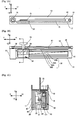
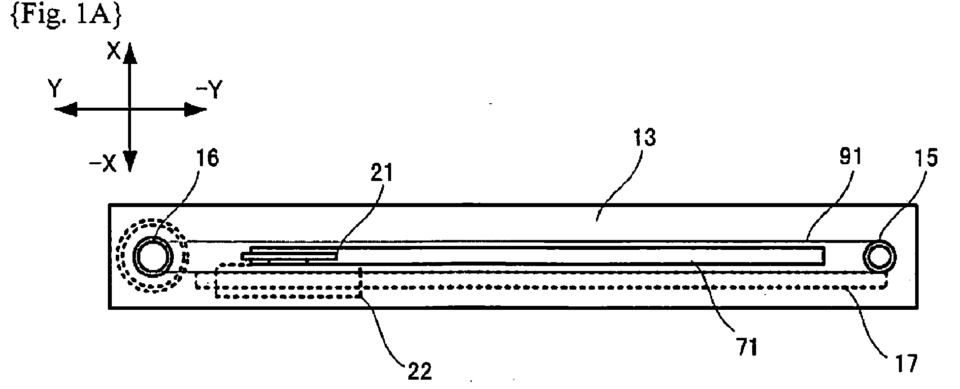
- Figs. 1A, 1B, and 1C are diagrams illustrating a slide operation apparatus according to an embodiment of the invention.
- Fig. 1A is a top view
- Fig. 1B is a side view in which a part of housing is omitted
- Fig. 1C is a cross-sectional view taken along the line A-A.
- the slide operation apparatus is used as a fader that is, for example, used in a manner of multiple faders arranged in an acoustic mixer.
- the slide operation apparatus includes, in appearance, a first lower housing 11, a second lower housing 12, and an upper housing 13.
- the first lower housing 11 and the second lower housing 12 are constituted of thin metal plates, and are coupled to each other so as to constitute a hollow housing in a rectangular parallelepiped shape.
- the first lower housing 11 forms a first side surface (a side surface at the X direction side in the drawings), a part of an inferior surface (at the -Z direction side in the drawings), and a part of a top surface (at the Z direction side in the drawings) of the slide operation apparatus.
- the second lower housing 12 forms a second side surface (a side surface at the -X direction side in the drawing), a part of the inferior surface, and a part of the top surface of the slide operation apparatus.
- the first lower housing 11 and the second lower housing 12 also form a front surface (at the Y direction side) and a back surface (at the -Y direction side).
- the slide shaft 17 extends in the longitudinal direction (the Y and -Y directions) of these housings.
- the moving body 22 is slidably supported by the slide shaft 17 and can be moved in the longitudinal direction of the slide shaft 17.
- the slide shaft 17 is a metal bar in a columnar shape and has both end portions secured to the respective first lower housing 11 and second lower housing 12.
- the respective top surfaces of the first lower housing 11 and the second lower housing 12 are coupled to an upper housing 13.
- the upper housing 13 includes a horizontal portion and a standing portion.
- the horizontal portion is coupled to the first lower housing 11 and the second lower housing 12.
- the standing portion is disposed upright from both sides of the horizontal portion to the top side.
- a slit 71 extending in the longitudinal direction is formed.
- a void between the first lower housing 11 and the second lower housing 12 is arranged.
- a thin sheet-shaped control 21 is exposed. The control 21 extends from the moving body 22 to the top side.
- the moving body 22 includes a slide housing 23 in a rectangular parallelepiped shape, a cylindrical member 171, and a guide shaft 24.
- the slide housing 23 is coupled with the operator 21.
- the cylindrical member 171 is coupled with the operator 21 and allows insertion of the slide shaft 17.
- the guide shaft 24 is coupled to the slide housing 23 and extends in the X direction from a surface on a side opposite to another surface coupled with the slide housing 23. That is, the respective configurations (the operator 21, the slide housing 23, the cylindrical member 171, and the guide shaft 24) illustrated in the shaded area of Fig. 1C are all integrally coupled together.
- a receiving pulley 15 and a drive pulley 16 are mounted on the end portions in the longitudinal direction.
- a timing belt 91 is mounted on the receiving pulley 15 and the drive pulley 16.
- a motor 51 is mounted on the drive pulley 16.
- the timing belt 91 is coupled with the control 21. Accordingly, when the timing belt 91 moves in association with the rotation of the motor 51, the control 21 moves in the longitudinal direction. Accordingly, the cylindrical member 171 of the moving body 22, which is coupled with the operator 21, slides on the slide shaft 17 and the moving body 22 slides to move.
- the slide housing 23 includes a groove on the inferior surface side.
- a guide plate 121 which is an end portion of the second lower housing 12, is inserted into the groove such that the moving body 22 is held slidably in the longitudinal direction.
- the moving body 22 can be not only moved by the motor 51, but also slid by manual operation on the control 21 by a user.
- This slide operation apparatus detects slide position of the moving body 22 and outputs information indicative of the detected slide position to a control unit (not illustrated) of an acoustic mixer. Subsequently, the control unit of the acoustic mixer sets parameters such as a sound volume, a sound quality, and an effect according to the information.
- the guide shaft 24 extending from the slide housing 23 in the X direction is in contact with the magnet 25 through a hole disposed in the magnet case 31.
- the number of the guide shafts 24 is not limited to the example (three) in the embodiment.
- the guide shaft 24 corresponds to a contact portion, and is not coupled with the magnet case 31 and the magnet 25. That is, the moving body 22 is not integrated with the magnet case 31 and the magnet 25, thus forming a separate component. Accordingly, the moving body 22 transmits a moving force, which is transmitted to the operator 21, to the magnet case 31 and the magnet 25 while the moving body 22 can move in a direction other than the longitudinal direction (the X and -X directions) to some extent.
- the magnet 25 is a ferrite magnet in a rectangular parallelepiped shape.
- the magnet case 31 is coupled with the magnet 25.
- the magnet case 31 has a shape that opens to the X direction and covers the magnet 25.
- X direction side end portions of the magnet case 31 extend to the Z direction and the -Z direction, and the magnet case 31 is coupled with the -X direction side surface of the movable electrode 26.
- the movable electrode 26 is a rectangular plane electrode formed on a printed circuit board and is covered with an insulator.
- a sliding member (sheet) 261 is attached to an X direction side surface of the insulator, among surfaces of the insulator.
- the sliding member 261 is made of a material (for example, foamed high-molecular polyethylene) with a low friction coefficient and high durability.
- the sliding member 261 is in contact with a fixed electrode 30.
- the fixed electrode 30 is constituted of plane electrodes (a first induction electrode 32A, a second induction electrode 32B, a potential detecting electrode 33A, and a potential detecting electrode 33B) formed on a printed circuit board, and is covered with an insulator.
- the printed circuit board is coupled with the first lower housing 11.
- the first lower housing 11 is formed of a magnetic material such as a galvanized steel sheet.
- the second lower housing 12 and the upper housing 13 employ a member (such as SUS) that is lightweight and has high strength.
- the movable electrode 26 is crimped to the fixed electrode 30 due to attraction of the above-described magnet 25 to the first lower housing 11 by a magnetic force.
- the intensity of the magnetic field of the magnet 25 is adjusted so as to crimp the movable electrode 26 and the fixed electrode 30 together while allowing the movable electrode 26 to slide with a small operating force. Accordingly, the movable electrode 26 can slide in the longitudinal direction while facing the fixed electrode 30 at a certain distance via the sliding member 261 attached to the surface of the insulator.
- the sliding member 261 may be attached to the surface of the movable electrode 26.
- the first lower housing 11 may be substituted by a magnet and the magnet 25 may be substituted by a magnetic material.
- This embodiment has a structure where the magnet is arranged inside the housing, thus preventing leakage of magnetic flux to the outside of the housing to reduce the influence on other components.
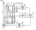
- Fig. 2 is a block diagram of an electrostatic sensor.
- the electrostatic sensor includes the above-described fixed electrode 30, the movable electrode 26 facing the fixed electrode 30, a power feeding unit 102, an analyzing unit 103, a motor driving unit 104, and a control unit 101.
- the power feeding unit 102 feeds power to the fixed electrode 30.
- the analyzing unit 103 detects capacitance between the fixed electrode 30 and the movable electrode 26 so as to detect position of the movable electrode 26.
- the control unit 101 is a functional unit that integrally controls the respective configurations.
- the control unit 101 controls the motor driving unit 104 to drive the motor 51 and moves the timing belt 91 so as to move the movable electrode 26.
- the fixed electrode 30 is constituted of the first induction electrode 32A, the second induction electrode 32B, the potential detecting electrode 33A, and the potential detecting electrode 33B.
- the first induction electrode 32A and the second induction electrode 32B are respectively a plane electrode that is long in the longitudinal direction of the slide operation apparatus and formed in a rectangular shape.
- the potential detecting electrode 33A and the potential detecting electrode 33B are arranged in a region between the first induction electrode 32A and the second induction electrode 32B.
- the potential detecting electrode 33A and the potential detecting electrode 33B are plane electrodes in which electrode patterns change along the longitudinal direction of the slide operation apparatus (the electrode patterns are respectively in right triangle shapes in this example), and are arranged close to each other in a point-symmetrical relationship. Lengths of the potential detecting electrode 33A and the potential detecting electrode 33B in the longitudinal direction are the same as lengths of the first induction electrode 32A and the second induction electrode 32B in the longitudinal direction.
- the first induction electrode 32A and the second induction electrode 32B are respectively coupled to the power feeding unit 102.
- the potential detecting electrode 33A and the potential detecting electrode 33B are respectively coupled to the analyzing unit 103.
- the power feeding unit 102 outputs, for example, a transmission signal (a rectangular wave) in which a voltage changes in pulse shape in accordance with control of the control unit 101, so as to apply voltage to the induction electrode 32A and the induction electrode 32B.
- a transmission signal a rectangular wave
- Amounts of electric charges induced in the potential detecting electrode 33A and the potential detecting electrode 33B depend on the area of respective portions facing the movable electrode 26. Accordingly, for example, the amount of electric charges induced in the potential detecting electrode 33B becomes larger as the movable electrode 26 becomes closer to the motor 51 side. The amount of electric charges induced in the potential detecting electrode 33A becomes larger as the movable electrode 26 becomes farer from the motor 51.
- the analyzing unit 103 obtains a difference value of amounts of the current based on the amount of electric charges induced in the potential detecting electrode 33A and the potential detecting electrode 33B, so as to detect the present position (the absolute position) of the movable electrode 26. Information on the detected position is outputted to the control unit 101 and then outputted from the control unit 101 to a control unit (not illustrated) of the acoustic mixer.
- the electrostatic sensor can detect slide position of the movable electrode 26, that is, slide position of the moving body 22. Subsequently, in the electrostatic sensor, the fixed electrode 30 and the movable electrode 26 are crimped together by the magnetic force. Thus, a uniform pressure is applied in a wide area. This allows the movable electrode 26 to slide while ensuring a constant interelectrode distance without using a precision mechanical component or a component in a complex shape.
- the arrangement pattern of the potential detecting electrode is not limited to this example.
- the invention can be used for an instrument that detects a position of a moving body to operate, for example, an operating unit of an electronic musical instrument and a movable portion of a general measuring instrument other than faders of the acoustic mixer described in the above embodiment.
Landscapes
- Physics & Mathematics (AREA)
- General Physics & Mathematics (AREA)
- Engineering & Computer Science (AREA)
- Power Engineering (AREA)
- Adjustable Resistors (AREA)
- Measurement Of Length, Angles, Or The Like Using Electric Or Magnetic Means (AREA)
- Transmission And Conversion Of Sensor Element Output (AREA)
Abstract
An electrostatic sensor includes a fixed electrode (30), a movable electrode (26), an analyzing unit (103), a sliding member (261), and a crimping member (25, 11). The fixed electrode (30) is arranged along a predetermined direction. The movable electrode (26) faces the fixed electrode (3 0). The analyzing unit (103) is configured to detect a position of the movable electrode (26) based on capacitance between the movable electrode (26) and the fixed electrode (30). The sliding member (261) is disposed between the fixed electrode (30) and the movable electrode (26). The crimping member (25, 11) crimps the fixed electrode (30) and the movable electrode (26) together by a magnetic force.

Description
- The invention relates to an electrostatic sensor that detects a position using a change in electric potential and to a slide operation apparatus that includes the electrostatic sensor.
- An electronic musical instrument, an acoustic mixer, or similar instrument employs a slide operation apparatus that includes faders. In the fader, a control such as a knob disposed in an upper portion of a main body in a box shape is slid to set parameters such as a sound volume, a sound quality, and an effect corresponding to a slide position of the control.
- On the fader, a position detecting device for detecting the slide position of the control is mounted. For example, PTL 1 discloses a configuration where a control is pressed against the top surface of a resistive element and the resistance value that changes corresponding to the position change of the operator is detected so as to detect the slide position.
- However, in the method that detects the position by change of the resistance value, the resistance value may be changed by contamination, abrasion, or similar defects of a contacting portion between the operator and the resistive element.
- Therefore, for example, an electrostatic sensor is known as a contactless position detecting sensor with high reliability and durability (see PTL 2).
-
- {PTL1}
JP 2002-124405 A - {PTL 2}
JP 2011-47679 A - However, in the electrostatic sensor, a change in interelectrode distance changes the electric potential due to electrostatic induction. Accordingly, it is necessary to keep a constant interelectrode distance with high accuracy.
- Therefore, an object of the invention is to provide an electrostatic sensor that keeps a constant interelectrode distance without using a precision mechanical component or a component in a complex shape for ensuring position accuracy.
- An electrostatic sensor of the invention includes a fixed electrode, a movable electrode, and an analyzing unit. The fixed electrode is arranged along a predetermined direction. The movable electrode faces the fixed electrode. The analyzing unit is configured to detect a position of the movable electrode based on capacitance between the movable electrode and the fixed electrode.
- Additionally, the electrostatic sensor includes a sliding member and a crimping member. The sliding member is disposed between the fixed electrode and the movable electrode. The crimping member crimps the fixed electrode and the movable electrode together by magnetic force.
- Accordingly, the electrostatic sensor of the invention crimps the electrodes with each other by magnetic force. This allows applying a uniform pressure in a wide area compared with a method for crimping using a leaf spring or similar configuration, thus allowing the slide of the movable electrode while ensuring a constant interelectrode distance without using a precision mechanical component or a component in a complex shape. Additionally, adjusting the intensity of the magnetic field easily controls the pressure in the crimping. This ensures a constant interelectrode distance while enabling to slide the movable electrode with a small operating force.
- The crimping member preferably includes a housing made of magnetic material and a magnet arranged inside the housing. It is preferable that the housing and the magnet form are structured such that the housing and the magnet sandwich the fixed electrode and the movable electrode between them. Accordingly, when the magnet is arranged inside the housing, the magnetic flux does not leak out of the housing. This reduces the influence on other components.
- The sliding member is preferably made of a material with a low friction coefficient and high durability, for example, high-molecular polyethylene.
- The electrostatic sensor of the invention is used together with a moving body that moves in a predetermined direction, so as to function as a slide operation apparatus. In this case, it is preferable that the moving body includes a contact portion in contact with a part of the crimping member. The contact portion transmits a moving force transmitted to the moving body to the crimping member. It is preferable that the movable electrode moves in the predetermined direction in association with movement of the moving body. That is, all the components are not preferably integrated. While the fixed electrode and the movable electrode are crimped together, the moving body itself preferably transmits a moving force to the movable electrode as a separate component. This structure ensures a margin such that the moving body itself can move in directions other than the predetermined direction to some extent. This eliminates the need for excessively high dimension accuracy of the components, thus facilitating the production.
- The invention enables to keep a constant interelectrode distance without using a precision mechanical component or a component in a complex shape for ensuring position accuracy.
-
- {
Fig. 1A} Fig. 1A is a top view of a slide operation apparatus. - {
Fig. 1B} Fig. 1B is a side view of the slide operation apparatus. - {
Fig. 1C} Fig. 1C is a cross-sectional view of the slide operation apparatus taken along the line A-A inFig. 1B . - {
Fig. 2} Fig. 2 is a block diagram of an electrostatic sensor. - The following describes an embodiment of the invention with reference to the drawings.
Figs. 1A, 1B, and 1C are diagrams illustrating a slide operation apparatus according to an embodiment of the invention.Fig. 1A is a top view,Fig. 1B is a side view in which a part of housing is omitted, andFig. 1C is a cross-sectional view taken along the line A-A. - The slide operation apparatus is used as a fader that is, for example, used in a manner of multiple faders arranged in an acoustic mixer. The slide operation apparatus includes, in appearance, a first
lower housing 11, a secondlower housing 12, and anupper housing 13. - The first
lower housing 11 and the secondlower housing 12 are constituted of thin metal plates, and are coupled to each other so as to constitute a hollow housing in a rectangular parallelepiped shape. The firstlower housing 11 forms a first side surface (a side surface at the X direction side in the drawings), a part of an inferior surface (at the -Z direction side in the drawings), and a part of a top surface (at the Z direction side in the drawings) of the slide operation apparatus. The secondlower housing 12 forms a second side surface (a side surface at the -X direction side in the drawing), a part of the inferior surface, and a part of the top surface of the slide operation apparatus. Although not illustrated in the drawings, the firstlower housing 11 and the secondlower housing 12 also form a front surface (at the Y direction side) and a back surface (at the -Y direction side). - Inside the first
lower housing 11 and the secondlower housing 12, aslide shaft 17 and a movingbody 22 are disposed. Theslide shaft 17 extends in the longitudinal direction (the Y and -Y directions) of these housings. The movingbody 22 is slidably supported by theslide shaft 17 and can be moved in the longitudinal direction of theslide shaft 17. Theslide shaft 17 is a metal bar in a columnar shape and has both end portions secured to the respective firstlower housing 11 and secondlower housing 12. - The respective top surfaces of the first
lower housing 11 and the secondlower housing 12 are coupled to anupper housing 13. Theupper housing 13 includes a horizontal portion and a standing portion. The horizontal portion is coupled to the firstlower housing 11 and the secondlower housing 12. The standing portion is disposed upright from both sides of the horizontal portion to the top side. - In the horizontal portion of the
upper housing 13, aslit 71 extending in the longitudinal direction is formed. On the inferior surface side of theslit 71, a void between the firstlower housing 11 and the secondlower housing 12 is arranged. From this slit 71, a thin sheet-shapedcontrol 21 is exposed. Thecontrol 21 extends from the movingbody 22 to the top side. - As illustrated in
Fig. 1C , the movingbody 22 includes aslide housing 23 in a rectangular parallelepiped shape, acylindrical member 171, and aguide shaft 24. Theslide housing 23 is coupled with theoperator 21. Thecylindrical member 171 is coupled with theoperator 21 and allows insertion of theslide shaft 17. Theguide shaft 24 is coupled to theslide housing 23 and extends in the X direction from a surface on a side opposite to another surface coupled with theslide housing 23. That is, the respective configurations (theoperator 21, theslide housing 23, thecylindrical member 171, and the guide shaft 24) illustrated in the shaded area ofFig. 1C are all integrally coupled together. - In the horizontal portion of the
upper housing 13, a receivingpulley 15 and adrive pulley 16 are mounted on the end portions in the longitudinal direction. On the receivingpulley 15 and thedrive pulley 16, atiming belt 91 is mounted. On thedrive pulley 16, amotor 51 is mounted. Thetiming belt 91 is coupled with thecontrol 21. Accordingly, when thetiming belt 91 moves in association with the rotation of themotor 51, thecontrol 21 moves in the longitudinal direction. Accordingly, thecylindrical member 171 of the movingbody 22, which is coupled with theoperator 21, slides on theslide shaft 17 and the movingbody 22 slides to move. - The
slide housing 23 includes a groove on the inferior surface side. Aguide plate 121, which is an end portion of the secondlower housing 12, is inserted into the groove such that the movingbody 22 is held slidably in the longitudinal direction. - The moving
body 22 can be not only moved by themotor 51, but also slid by manual operation on thecontrol 21 by a user. - This slide operation apparatus detects slide position of the moving
body 22 and outputs information indicative of the detected slide position to a control unit (not illustrated) of an acoustic mixer. Subsequently, the control unit of the acoustic mixer sets parameters such as a sound volume, a sound quality, and an effect according to the information. - The following describes a configuration of the slide-position detection of the moving
body 22. As illustrated inFig. 1B and Fig. 1C , theguide shaft 24 extending from theslide housing 23 in the X direction is in contact with themagnet 25 through a hole disposed in themagnet case 31. Here, the number of theguide shafts 24 is not limited to the example (three) in the embodiment. - The
guide shaft 24 corresponds to a contact portion, and is not coupled with themagnet case 31 and themagnet 25. That is, the movingbody 22 is not integrated with themagnet case 31 and themagnet 25, thus forming a separate component. Accordingly, the movingbody 22 transmits a moving force, which is transmitted to theoperator 21, to themagnet case 31 and themagnet 25 while the movingbody 22 can move in a direction other than the longitudinal direction (the X and -X directions) to some extent. - The
magnet 25 is a ferrite magnet in a rectangular parallelepiped shape. Themagnet case 31 is coupled with themagnet 25. Themagnet case 31 has a shape that opens to the X direction and covers themagnet 25. X direction side end portions of themagnet case 31 extend to the Z direction and the -Z direction, and themagnet case 31 is coupled with the -X direction side surface of themovable electrode 26. - As illustrated also in
Fig. 2 , themovable electrode 26 is a rectangular plane electrode formed on a printed circuit board and is covered with an insulator. A sliding member (sheet) 261 is attached to an X direction side surface of the insulator, among surfaces of the insulator. The slidingmember 261 is made of a material (for example, foamed high-molecular polyethylene) with a low friction coefficient and high durability. - The sliding
member 261 is in contact with a fixedelectrode 30. The fixedelectrode 30 is constituted of plane electrodes (afirst induction electrode 32A, asecond induction electrode 32B, apotential detecting electrode 33A, and apotential detecting electrode 33B) formed on a printed circuit board, and is covered with an insulator. The printed circuit board is coupled with the firstlower housing 11. The firstlower housing 11 is formed of a magnetic material such as a galvanized steel sheet. Here, the secondlower housing 12 and theupper housing 13 employ a member (such as SUS) that is lightweight and has high strength. - Accordingly, the
movable electrode 26 is crimped to the fixedelectrode 30 due to attraction of the above-describedmagnet 25 to the firstlower housing 11 by a magnetic force. The intensity of the magnetic field of themagnet 25 is adjusted so as to crimp themovable electrode 26 and the fixedelectrode 30 together while allowing themovable electrode 26 to slide with a small operating force. Accordingly, themovable electrode 26 can slide in the longitudinal direction while facing the fixedelectrode 30 at a certain distance via the slidingmember 261 attached to the surface of the insulator. - Here, the sliding
member 261 may be attached to the surface of themovable electrode 26. - The first
lower housing 11 may be substituted by a magnet and themagnet 25 may be substituted by a magnetic material. This embodiment has a structure where the magnet is arranged inside the housing, thus preventing leakage of magnetic flux to the outside of the housing to reduce the influence on other components. - Next,
Fig. 2 is a block diagram of an electrostatic sensor. The electrostatic sensor includes the above-describedfixed electrode 30, themovable electrode 26 facing the fixedelectrode 30, apower feeding unit 102, an analyzingunit 103, amotor driving unit 104, and acontrol unit 101. Thepower feeding unit 102 feeds power to the fixedelectrode 30. The analyzingunit 103 detects capacitance between the fixedelectrode 30 and themovable electrode 26 so as to detect position of themovable electrode 26. - The
control unit 101 is a functional unit that integrally controls the respective configurations. Thecontrol unit 101 controls themotor driving unit 104 to drive themotor 51 and moves thetiming belt 91 so as to move themovable electrode 26. - The fixed
electrode 30 is constituted of thefirst induction electrode 32A, thesecond induction electrode 32B, thepotential detecting electrode 33A, and thepotential detecting electrode 33B. Thefirst induction electrode 32A and thesecond induction electrode 32B are respectively a plane electrode that is long in the longitudinal direction of the slide operation apparatus and formed in a rectangular shape. Thepotential detecting electrode 33A and thepotential detecting electrode 33B are arranged in a region between thefirst induction electrode 32A and thesecond induction electrode 32B. - The
potential detecting electrode 33A and thepotential detecting electrode 33B are plane electrodes in which electrode patterns change along the longitudinal direction of the slide operation apparatus (the electrode patterns are respectively in right triangle shapes in this example), and are arranged close to each other in a point-symmetrical relationship. Lengths of thepotential detecting electrode 33A and thepotential detecting electrode 33B in the longitudinal direction are the same as lengths of thefirst induction electrode 32A and thesecond induction electrode 32B in the longitudinal direction. - The
first induction electrode 32A and thesecond induction electrode 32B are respectively coupled to thepower feeding unit 102. Thepotential detecting electrode 33A and thepotential detecting electrode 33B are respectively coupled to the analyzingunit 103. - The
power feeding unit 102 outputs, for example, a transmission signal (a rectangular wave) in which a voltage changes in pulse shape in accordance with control of thecontrol unit 101, so as to apply voltage to theinduction electrode 32A and theinduction electrode 32B. - When the voltage from the
power feeding unit 102 is applied to theinduction electrode 32A and theinduction electrode 32B, electric charges are induced in themovable electrode 26 by an effect of electrostatic induction. - When the electric charges are induced in the
movable electrode 26, electric charges are further induced in thepotential detecting electrode 33A and thepotential detecting electrode 33B by an effect of electrostatic induction. - Amounts of electric charges induced in the
potential detecting electrode 33A and thepotential detecting electrode 33B depend on the area of respective portions facing themovable electrode 26. Accordingly, for example, the amount of electric charges induced in thepotential detecting electrode 33B becomes larger as themovable electrode 26 becomes closer to themotor 51 side. The amount of electric charges induced in thepotential detecting electrode 33A becomes larger as themovable electrode 26 becomes farer from themotor 51. - The analyzing
unit 103 obtains a difference value of amounts of the current based on the amount of electric charges induced in thepotential detecting electrode 33A and thepotential detecting electrode 33B, so as to detect the present position (the absolute position) of themovable electrode 26. Information on the detected position is outputted to thecontrol unit 101 and then outputted from thecontrol unit 101 to a control unit (not illustrated) of the acoustic mixer. - As described above, the electrostatic sensor can detect slide position of the
movable electrode 26, that is, slide position of the movingbody 22. Subsequently, in the electrostatic sensor, the fixedelectrode 30 and themovable electrode 26 are crimped together by the magnetic force. Thus, a uniform pressure is applied in a wide area. This allows themovable electrode 26 to slide while ensuring a constant interelectrode distance without using a precision mechanical component or a component in a complex shape. - While in this embodiment the example where two of the
potential detecting electrode 33A and thepotential detecting electrode 33B in the triangular shapes are arranged has been described, the arrangement pattern of the potential detecting electrode is not limited to this example. - The invention can be used for an instrument that detects a position of a moving body to operate, for example, an operating unit of an electronic musical instrument and a movable portion of a general measuring instrument other than faders of the acoustic mixer described in the above embodiment.
- 11... first lower housing, 12... second lower housing, 13... upper housing, 15... receiving pulley, 16... drive pulley, 17... slide shaft, 21... control, 22... moving body, 23... slide housing, 24... guide shaft, 25... magnet, 26... movable electrode, 30... fixed electrode, 31... magnet case, 51... motor, 71... slit, 91... timing belt
Claims (4)
- An electrostatic sensor, comprising:a fixed electrode (30) arranged along a predetermined direction;a movable electrode (26) that faces the fixed electrode (30);an analyzing unit (103) configured to detect a position of the movable electrode (26) based on capacitance between the movable electrode (26) and the fixed electrode (30);a sliding member (261) disposed between the fixed electrode (30) and the movable electrode (26); anda crimping member (25, 11) that crimps the fixed electrode (30) and the movable electrode (26) together by a magnetic force.
- The electrostatic sensor according to claim 1,
wherein the crimping member (25, 11) includes a housing (11) made of magnetic material and a magnet (25) arranged inside the housing (11), and
the housing (11) and the magnet (25) form a structure that the housing (11) and the magnet (25) sandwiches the fixed electrode (30) and the movable electrode (26). - The electrostatic sensor according to claim 1 or 2,
wherein the sliding member is made of high-molecular polyethylene. - A slide operation apparatus, comprising:the electrostatic sensor according to any one of claims 1 to 3; anda moving body (22) configured to move in a predetermined direction,wherein the moving body (22) comprises a contact portion (24) in contact with a part of the crimping member (25), andthe contact portion (24) is configured to transmit a moving force transmitted to the moving body (22) to the crimping member (25) such that the movable electrode (26) moves in the predetermined direction in association with movement of the moving body (22).
Applications Claiming Priority (1)
| Application Number | Priority Date | Filing Date | Title |
|---|---|---|---|
| JP2013054841A JP2014181929A (en) | 2013-03-18 | 2013-03-18 | Electrostatic sensor, and slide operation device |
Publications (1)
| Publication Number | Publication Date |
|---|---|
| EP2781889A1 true EP2781889A1 (en) | 2014-09-24 |
Family
ID=50289467
Family Applications (1)
| Application Number | Title | Priority Date | Filing Date |
|---|---|---|---|
| EP14160169.0A Withdrawn EP2781889A1 (en) | 2013-03-18 | 2014-03-17 | Electrostatic sensor and slide operation apparatus |
Country Status (4)
| Country | Link |
|---|---|
| US (1) | US20140266252A1 (en) |
| EP (1) | EP2781889A1 (en) |
| JP (1) | JP2014181929A (en) |
| CN (1) | CN104061949A (en) |
Cited By (2)
| Publication number | Priority date | Publication date | Assignee | Title |
|---|---|---|---|---|
| CN105372505A (en) * | 2015-12-11 | 2016-03-02 | 得理电子(上海)有限公司 | Device and method for measuring distance based on capacitance values, and application thereof |
| RU2723971C1 (en) * | 2020-01-28 | 2020-06-18 | Общество С Ограниченной Ответственностью "Конструкторское Бюро "Дорс" (Ооо "Кб "Дорс") | Electrostatic sensor for controlling a movable thin object |
Families Citing this family (1)
| Publication number | Priority date | Publication date | Assignee | Title |
|---|---|---|---|---|
| JP6507508B2 (en) * | 2014-07-16 | 2019-05-08 | カシオ計算機株式会社 | Tone control device, electronic musical instrument, tone control method and program |
Citations (4)
| Publication number | Priority date | Publication date | Assignee | Title |
|---|---|---|---|---|
| JP2002124405A (en) | 2000-10-16 | 2002-04-26 | Matsushita Electric Ind Co Ltd | Slide type variable resistor |
| US20050052429A1 (en) * | 2003-08-21 | 2005-03-10 | Harald Philipp | Capacitive position sensor |
| US20100241382A1 (en) * | 2009-03-17 | 2010-09-23 | Olympus Corporation | Calibration method for inertial drive actuator, inertial drive actuator device, and method of calculating position of moving body |
| JP2011047679A (en) | 2009-08-25 | 2011-03-10 | Seidensha Co Ltd | Electrostatic encoder |
Family Cites Families (5)
| Publication number | Priority date | Publication date | Assignee | Title |
|---|---|---|---|---|
| WO2000005548A1 (en) * | 1998-07-24 | 2000-02-03 | Next Corporation | Displacement detector |
| US6492911B1 (en) * | 1999-04-19 | 2002-12-10 | Netzer Motion Sensors Ltd. | Capacitive displacement encoder |
| JP4297146B2 (en) * | 2006-09-21 | 2009-07-15 | ヤマハ株式会社 | Slide operation device |
| EP2315039A4 (en) * | 2008-07-04 | 2012-10-10 | Alps Electric Co Ltd | MOVABLE SENSOR OF CAPACITY DETECTION TYPE |
| JP2010043894A (en) * | 2008-08-11 | 2010-02-25 | Yamaha Corp | Slide operation device |
-
2013
- 2013-03-18 JP JP2013054841A patent/JP2014181929A/en active Pending
-
2014
- 2014-03-17 EP EP14160169.0A patent/EP2781889A1/en not_active Withdrawn
- 2014-03-17 CN CN201410098586.XA patent/CN104061949A/en active Pending
- 2014-03-18 US US14/218,097 patent/US20140266252A1/en not_active Abandoned
Patent Citations (4)
| Publication number | Priority date | Publication date | Assignee | Title |
|---|---|---|---|---|
| JP2002124405A (en) | 2000-10-16 | 2002-04-26 | Matsushita Electric Ind Co Ltd | Slide type variable resistor |
| US20050052429A1 (en) * | 2003-08-21 | 2005-03-10 | Harald Philipp | Capacitive position sensor |
| US20100241382A1 (en) * | 2009-03-17 | 2010-09-23 | Olympus Corporation | Calibration method for inertial drive actuator, inertial drive actuator device, and method of calculating position of moving body |
| JP2011047679A (en) | 2009-08-25 | 2011-03-10 | Seidensha Co Ltd | Electrostatic encoder |
Cited By (2)
| Publication number | Priority date | Publication date | Assignee | Title |
|---|---|---|---|---|
| CN105372505A (en) * | 2015-12-11 | 2016-03-02 | 得理电子(上海)有限公司 | Device and method for measuring distance based on capacitance values, and application thereof |
| RU2723971C1 (en) * | 2020-01-28 | 2020-06-18 | Общество С Ограниченной Ответственностью "Конструкторское Бюро "Дорс" (Ооо "Кб "Дорс") | Electrostatic sensor for controlling a movable thin object |
Also Published As
| Publication number | Publication date |
|---|---|
| CN104061949A (en) | 2014-09-24 |
| JP2014181929A (en) | 2014-09-29 |
| US20140266252A1 (en) | 2014-09-18 |
Similar Documents
| Publication | Publication Date | Title |
|---|---|---|
| EP3141911A1 (en) | Voltage detecting probe and measuring device | |
| US9417094B2 (en) | Displacement sensor for force indicating caliper | |
| CN103597322B (en) | Capacitive displacement transducer | |
| US8742783B2 (en) | Contactor | |
| CN103562733B (en) | Spring contact contact pin apparatus | |
| EP3115792B1 (en) | Voltage detecting probe and measuring device | |
| US20140266252A1 (en) | Electrostatic sensor and slide operation apparatus | |
| JP6665007B2 (en) | Voltage detection probe and measuring device | |
| RU2669089C2 (en) | Capacitive touch sensor | |
| EP2865624A1 (en) | Multi-feed detection device, and sheet-shaped-object handling device | |
| ES2748899T3 (en) | Inductive position determination | |
| CN105829897A (en) | Non-contact voltage measuring device | |
| JP6300027B2 (en) | Input device | |
| CN107086101B (en) | Gliding rheostat | |
| JP2006234428A (en) | Contact probe and inspection device | |
| CN101930012A (en) | Sensing device | |
| JP2010043894A (en) | Slide operation device | |
| JP2011047679A (en) | Electrostatic encoder | |
| JPH07208905A (en) | Contact-type displacement sensor and work measuring instrument using the sensor | |
| JP6679408B2 (en) | Voltage detection probe and measuring device | |
| JP2016173946A (en) | Slide operation apparatus | |
| JP6608251B2 (en) | Detection probe and measuring device | |
| US796675A (en) | Recording instrument. | |
| JPH06109410A (en) | Probe for gap-size measurement | |
| CN108228011A (en) | Operating device with first and second capacitive measuring unit, motor vehicle and method for operating the operating device |
Legal Events
| Date | Code | Title | Description |
|---|---|---|---|
| PUAI | Public reference made under article 153(3) epc to a published international application that has entered the european phase |
Free format text: ORIGINAL CODE: 0009012 |
|
| 17P | Request for examination filed |
Effective date: 20140317 |
|
| AK | Designated contracting states |
Kind code of ref document: A1 Designated state(s): AL AT BE BG CH CY CZ DE DK EE ES FI FR GB GR HR HU IE IS IT LI LT LU LV MC MK MT NL NO PL PT RO RS SE SI SK SM TR |
|
| AX | Request for extension of the european patent |
Extension state: BA ME |
|
| STAA | Information on the status of an ep patent application or granted ep patent |
Free format text: STATUS: THE APPLICATION IS DEEMED TO BE WITHDRAWN |
|
| 18D | Application deemed to be withdrawn |
Effective date: 20150325 |