EP2781859A1 - Electronic expansion valve, and air conditioner - Google Patents
Electronic expansion valve, and air conditioner Download PDFInfo
- Publication number
- EP2781859A1 EP2781859A1 EP12849516.5A EP12849516A EP2781859A1 EP 2781859 A1 EP2781859 A1 EP 2781859A1 EP 12849516 A EP12849516 A EP 12849516A EP 2781859 A1 EP2781859 A1 EP 2781859A1
- Authority
- EP
- European Patent Office
- Prior art keywords
- valve
- opening degree
- valve portion
- region
- electronic expansion
- Prior art date
- Legal status (The legal status is an assumption and is not a legal conclusion. Google has not performed a legal analysis and makes no representation as to the accuracy of the status listed.)
- Granted
Links
Images



Classifications
-
- F—MECHANICAL ENGINEERING; LIGHTING; HEATING; WEAPONS; BLASTING
- F25—REFRIGERATION OR COOLING; COMBINED HEATING AND REFRIGERATION SYSTEMS; HEAT PUMP SYSTEMS; MANUFACTURE OR STORAGE OF ICE; LIQUEFACTION SOLIDIFICATION OF GASES
- F25B—REFRIGERATION MACHINES, PLANTS OR SYSTEMS; COMBINED HEATING AND REFRIGERATION SYSTEMS; HEAT PUMP SYSTEMS
- F25B41/00—Fluid-circulation arrangements
- F25B41/30—Expansion means; Dispositions thereof
- F25B41/31—Expansion valves
- F25B41/34—Expansion valves with the valve member being actuated by electric means, e.g. by piezoelectric actuators
- F25B41/35—Expansion valves with the valve member being actuated by electric means, e.g. by piezoelectric actuators by rotary motors, e.g. by stepping motors
-
- F—MECHANICAL ENGINEERING; LIGHTING; HEATING; WEAPONS; BLASTING
- F16—ENGINEERING ELEMENTS AND UNITS; GENERAL MEASURES FOR PRODUCING AND MAINTAINING EFFECTIVE FUNCTIONING OF MACHINES OR INSTALLATIONS; THERMAL INSULATION IN GENERAL
- F16K—VALVES; TAPS; COCKS; ACTUATING-FLOATS; DEVICES FOR VENTING OR AERATING
- F16K1/00—Lift valves or globe valves, i.e. cut-off apparatus with closure members having at least a component of their opening and closing motion perpendicular to the closing faces
- F16K1/32—Details
- F16K1/34—Cutting-off parts, e.g. valve members, seats
- F16K1/36—Valve members
-
- F—MECHANICAL ENGINEERING; LIGHTING; HEATING; WEAPONS; BLASTING
- F16—ENGINEERING ELEMENTS AND UNITS; GENERAL MEASURES FOR PRODUCING AND MAINTAINING EFFECTIVE FUNCTIONING OF MACHINES OR INSTALLATIONS; THERMAL INSULATION IN GENERAL
- F16K—VALVES; TAPS; COCKS; ACTUATING-FLOATS; DEVICES FOR VENTING OR AERATING
- F16K31/00—Actuating devices; Operating means; Releasing devices
- F16K31/02—Actuating devices; Operating means; Releasing devices electric; magnetic
- F16K31/04—Actuating devices; Operating means; Releasing devices electric; magnetic using a motor
-
- F—MECHANICAL ENGINEERING; LIGHTING; HEATING; WEAPONS; BLASTING
- F16—ENGINEERING ELEMENTS AND UNITS; GENERAL MEASURES FOR PRODUCING AND MAINTAINING EFFECTIVE FUNCTIONING OF MACHINES OR INSTALLATIONS; THERMAL INSULATION IN GENERAL
- F16K—VALVES; TAPS; COCKS; ACTUATING-FLOATS; DEVICES FOR VENTING OR AERATING
- F16K31/00—Actuating devices; Operating means; Releasing devices
- F16K31/02—Actuating devices; Operating means; Releasing devices electric; magnetic
- F16K31/04—Actuating devices; Operating means; Releasing devices electric; magnetic using a motor
- F16K31/041—Actuating devices; Operating means; Releasing devices electric; magnetic using a motor for rotating valves
- F16K31/042—Actuating devices; Operating means; Releasing devices electric; magnetic using a motor for rotating valves with electric means, e.g. for controlling the motor or a clutch between the valve and the motor
-
- Y—GENERAL TAGGING OF NEW TECHNOLOGICAL DEVELOPMENTS; GENERAL TAGGING OF CROSS-SECTIONAL TECHNOLOGIES SPANNING OVER SEVERAL SECTIONS OF THE IPC; TECHNICAL SUBJECTS COVERED BY FORMER USPC CROSS-REFERENCE ART COLLECTIONS [XRACs] AND DIGESTS
- Y02—TECHNOLOGIES OR APPLICATIONS FOR MITIGATION OR ADAPTATION AGAINST CLIMATE CHANGE
- Y02B—CLIMATE CHANGE MITIGATION TECHNOLOGIES RELATED TO BUILDINGS, e.g. HOUSING, HOUSE APPLIANCES OR RELATED END-USER APPLICATIONS
- Y02B30/00—Energy efficient heating, ventilation or air conditioning [HVAC]
- Y02B30/70—Efficient control or regulation technologies, e.g. for control of refrigerant flow, motor or heating
Definitions
- the present invention relates to an electronic expansion valve disposed in a refrigerant circuit of an air conditioner, and relates to an air conditioner.
- Patent Document 1 A technique disclosed by Patent Document 1 is known as an electronic expansion valve.
- a valve body is provided with a surface substantially parallel to a refrigerant flow path in order to improve the controllability of the amount of refrigerant flow in a small flow range.
- the amount of refrigerant flow is required to be slightly adjusted.
- an increase in the opening area with respect to the minimum movement range of the valve body is great, it will be difficult to increase or decrease the amount of refrigerant flow only slightly.
- the valve body is repeatedly moved forwardly or backwardly to finely adjust the opening degree.
- a basal part of the valve main body is parallel to the side surface of the refrigerant flow path over a predetermined distance, and therefore the opening area can hardly vary even if the valve body moves within this range.
- the amount of refrigerant flow hardly varies in some movement places of the valve body, and it is impossible to finely adjust the amount of refrigerant flow.
- Patent Document 1 Japanese Laid-Open Patent Publication No. H10-148420
- An object of the present invention is to provide an electronic expansion valve capable of finely adjusting the amount of refrigerant flow and provide an air conditioner.
- an electronic expansion valve which includes a valve body whose forward end is provided with a valve portion, a valve seat that forms a variable throttle portion between the valve portion and the valve seat by allowing the valve body to move in an axial direction, and a stepping motor that moves the valve body in accordance with a pulse number.
- an opening area When an area of a cross section of a gap formed between the valve portion and the valve seat and that is perpendicular to the axial direction is defined as an opening area and when an area ratio between an opening area in which the pulse number has not yet been increased and decreased and an opening area in which the pulse number has already been increased and decreased is defined as an opening degree ratio, at least one part of a side surface of the valve portion is shaped so that the opening degree ratio becomes constant.
- the opening degree ratio becomes constant. Therefore, the opening area increases at a fixed ratio when the valve body is moved. Therefore, the variation ratio of the amount of refrigerant flow becomes constant. Therefore, the amount of refrigerant flow can be finely adjusted.
- 'The opening degree ratio is constant includes 'The opening degree ratio is substantially constant.” In other words, besides a curved surface shape in which the opening degree ratio is constant, surface in which a plurality of surfaces are included and a borderline of each surface is disposed on a curved surface is included. Additionally, an approximate curved surface approximated to this curved surface is also included.
- the side surface of the valve portion is divided into three or more regions in the axial direction, and a borderline of each of the regions is disposed on a virtual curved surface in which the opening degree ratio becomes constant.
- the side surface of each region is disposed on the virtual curved surface in which the opening degree ratio becomes constant. Therefore, the side surface of the valve portion is approximated to the virtual curved surface. As a result, the variation ratio of the amount of refrigerant flow becomes substantially constant over the moving range of the valve portion. Therefore, the amount of refrigerant flow can be finely adjusted.
- the interval length of each region becomes smaller toward a forward end of the valve portion in order of disposition of the regions.
- the side surface of each region is disposed on the virtual curved surface in which the opening degree ratio becomes constant. Additionally, the interval length of each region becomes smaller toward the forward end of the valve portion in order of disposition of the regions. Therefore, the amount of variation with respect to the movement amount of the valve portion becomes greater in proportion to an increase in the opening degree, and becomes smaller in proportion to a decrease in the opening degree. As a result, in a small opening degree range, the amount of refrigerant flow can be adjusted with higher accuracy than in a large opening degree range. On the other hand, there is no need to adjust the amount of refrigerant flow with high accuracy in a large opening degree range, and therefore the aforementioned arrangement can contribute to stabilizing the operation of the electronic expansion valve.
- the side surface of the valve portion is divided into a first region that corresponds to a part in which the opening degree is from 0% to less than 25%, a second region that corresponds to a part in which the opening degree is from 25% to less than 50%, a third region that corresponds to a part in which the opening degree is from 50% to less than 75%, and a fourth region that corresponds to a part in which the opening degree is from 75% to 100%, and the side surface of each region is a side surface shaped in a truncated cone, and the borderline of each region is disposed on a virtual curved surface in which the opening degree ratio becomes constant.
- the aspect of the side surface of the valve portion varies whenever the valve portion moves and the opening degree increases by 25%. Additionally, each borderline is disposed on the virtual curved surface in which the opening degree ratio becomes constant. Therefore, the valve portion can be more easily formed than in a case in which the side surface of the valve portion is a curved surface. Additionally, the flow-rate variation ratio can be made substantially constant over the moving range of the valve portion.
- the side surface of the valve portion is divided into a first region that corresponds to a part in which the opening degree is from 0% to less than 20%, a second region that corresponds to a part in which the opening degree is from 20% to less than 40%, a third region that corresponds to a part in which the opening degree is from 40% to less than 60%, a fourth region that corresponds to a part in which the opening degree is from 60% to less than 80%, and a fifth region that corresponds to a part in which the opening degree is from 80% to 100%, and the side surface of each region is a side surface shaped in a truncated cone, and the borderline of each region is disposed on a virtual curved surface in which the opening degree ratio becomes constant.
- the aspect of the side surface of the valve portion varies whenever the valve portion moves and the opening degree increases by 20%. Additionally each borderline is disposed on the virtual curved surface in which the opening degree ratio becomes constant. Therefore, the valve portion can be more easily formed than in a case in which the side surface of the valve portion is a curved surface. Additionally, the flow-rate variation ratio can be made substantially constant over the moving range of the valve portion.
- the side surface of the valve portion is a curved surface, and the opening degree ratio is ⁇ in the moving range of the valve portion. Therefore, a variation in the flow rate of a refrigerant can be made substantially constant over the moving range of the valve portion.
- an electronic expansion valve which includes a valve body whose forward end is provided with a valve portion, a valve seat that forms a variable throttle portion between the valve portion and the valve seat by allowing the valve body to move in an axial direction, and a stepping motor that moves the valve body in accordance with a pulse number.
- an angle ⁇ with respect to the valve axis of the valve portion satisfies the following formula: 0 ⁇ tan ⁇ ⁇ 0.2
- a region that is near the basal part of the valve portion and that occupies at least 1/5 of an interval between the basal part to the forward end has a side surface shape that satisfies the aforementioned formula.
- the opening area can be increased and decreased little by little with respect to the movement of the valve portion. Therefore, the amount of refrigerant flow can be finely adjusted in a small opening degree range.
- an air conditioner including the aforementioned electronic expansion valve is provided.
- the amount of refrigerant flow can be finely adjusted, and therefore air-conditioning performance by means of the air conditioner is stabilized.
- the air conditioner 1 is composed of a compressor 10 that compresses a refrigerant, an outdoor heat exchanger 20 that is disposed outdoors, an electronic expansion valve 30 that expands a refrigerant, an indoor heat exchanger 50 that is disposed indoors, a four-pass change-over valve 60, and a controller 70 that manages and controls each device.
- the electronic expansion valve 30 is composed of a first pipe 31 that serves as a gateway for a refrigerant, a second pipe 32, a rod-shaped valve body 40, a valve seat 33, a cylindrical member 35 that has a valve port 34, and a stepping motor 36 that drives the valve body 40 in an axial direction.
- the first pipe 31 serves as one gateway of the electronic expansion valve 30.
- the second pipe 32 serves as the other gateway of the electronic expansion valve 30.
- the second pipe 32 perpendicularly intersects the first pipe 31.
- the cylindrical member 35 connects the first pipe 31 and a valve chamber 37 together.
- a taper portion is formed near the valve chamber 37 of the valve port 34. The taper portion is a constituent of the valve seat 33.
- the valve body 40 is composed of a valve rod 41, a taper portion 42, and a valve portion 43 formed at a forward end of the valve rod 41 with the taper portion 42 therebetween.
- the valve rod 41 is fixed to a rotational shaft of the stepping motor 36.
- the taper portion 42 totally closes the electronic expansion valve 30 by coming into contact with the valve seat 33.
- the valve portion 43 is inserted in the valve port 34.
- the outer diameter of the valve portion 43 is smaller than the inner diameter of the valve port 34, and becomes smaller toward its forward end.
- a variable throttle portion is formed between the valve portion 43 and the valve seat 33 by allowing the valve portion 43 to move in the axial direction.
- the valve body 40 and the rotational shaft of the stepping motor 36 are connected together through a rotational conversion mechanism such as screws or gears.
- the rotational conversion mechanism converts the rotational motion of the rotational shaft of the stepping motor 36 into the linear motion of the valve body 40.
- the stepping motor 36 is driven by a pulse signal output from the controller 70.
- a pulse number and a rotation angle correlate with each other.
- the rotation angle of the rotational shaft of the stepping motor 36 becomes larger in proportion to the pulse number input to the stepping motor 36.
- the valve body 40 moves in the axial direction.
- the movement amount of the valve body 40 is proportional to the rotation angle of the stepping motor 36.
- the movement amount of the valve body 40 i.e., the movement amount of the valve portion 43 is proportional to the pulse number output to the stepping motor 36 from the controller 70.
- a temperature sensor 71 and a pressure sensor 72 are connected to the controller 70.
- the temperature sensor 71 detects the temperature of a refrigerant (hereinafter, referred to as refrigerant temperature), and outputs a refrigerant temperature signal corresponding to the refrigerant temperature to the controller 70.
- the pressure sensor 72 detects the pressure of a refrigerant (hereinafter, referred to as refrigerant pressure), and outputs a refrigerant pressure signal corresponding to the refrigerant pressure to the controller 70.
- the controller 70 counts a pulse number that is output to the stepping motor 36. Additionally, the controller 70 integrates the counted pulse number, and calculates and stores a pulse integrated value. A positive or negative sign is given to the pulse number.
- the pulse number is a negative value.
- the rotational shaft of the stepping motor 36 positively rotates in a direction in which the valve portion 43 comes out of the valve port 34 (hereinafter, referred to as leaving direction)
- the pulse number is a positive value.
- the position of the valve portion 43 located when the taper portion 42 of the valve body 40 comes into contact with the valve seat 33 is set as a reference position.
- the pulse integrated value of the controller 70 is reset, and the pulse integrated value becomes "0."
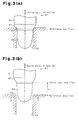
- Fig. 3(b) when the valve portion 43 leaves the reference position, a gap is generated between the valve portion 43 and a minimum diameter part of the valve seat 33.
- the position of the valve portion 43 is equal to the movement distance of the valve portion 43 from the reference position. Therefore, the position of the valve portion 43 is specified by a relationship with the pulse integrated value.
- the movement amount of the valve portion 43 from the reference position corresponds to the sum total of the pulse number counted during a movement from the reference position to a predetermined position.
- the position of the valve portion 43 corresponds to the pulse integrated value.
- the opening area is the area of the gap between the minimum diameter part of the valve seat 33 and the valve portion 43. More specifically, the opening area is a difference between the area SA of the minimum diameter part of the valve seat 33 and the cross-sectional area SB of the valve portion 43 along a plane including the minimum diameter part of the valve seat 33.
- the area SA and the cross-sectional area SB are both equivalent to the area of a cross section perpendicular to the axial direction.
- the opening area coincides with the area SA of the minimum diameter part of the valve seat 33, and corresponds to a maximum opening area Smax.
- the opening degree is a ratio (%) between the opening area when the valve portion 43 is in a predetermined position and the maximum opening area Smax.
- the opening degree is 0%.
- the opening degree is 100%.
- the opening degree approximately bears a proportional relationship with the amount of refrigerant flow.
- the opening degree is adjusted.
- An adjustment to the opening degree is made by use of a pulse integrated value.
- the opening degree becomes greater in proportion to an increase in the pulse integrated value.
- an increase aspect of the opening degree resulting from the pulse integrated value depends on a side surface structure of the valve portion 43. Therefore, when the opening degree is adjusted, the controller 70 uses a map showing a relationship between the opening degree and the pulse integrated value.
- a map in which the opening degree is expressed as a C-D ⁇ (E-Xa) 2 function with respect to the pulse integrated value Xa is used.
- a contribution of Xa 2 to the opening degree is great when the opening degree is adjusted in a small opening degree range.
- the amount of variation of the opening degree in a slight variation of the pulse integrated value Xa is great, and therefore it is difficult to finely adjust the opening degree, and it is difficult to finely adjust the flow rate. Therefore, in the present embodiment, a map that enables an easy opening-degree adjustment is assumed with the aim of controlling the opening degree with high accuracy. Additionally the applicant has devised a valve structure based on this map.
- the opening degree ratio (Y(X+1)/Y(X)) in two points that differ by 1 in the pulse integrated value X becomes " ⁇ ."
- the opening degree ratio is constant regardless of the pulse integrated value X.
- the opening degree ratio is constant with respect to the pulse integrated value X although the opening degree ratio (Y(X+ ⁇ )/Y(X)) also becomes great when the predetermined value ⁇ is made great.
- the fact that Formula (1) is satisfied is the same as the fact that Formula (2) is satisfied. If a map that satisfies Formula (1) is used, the opening degree ratio will become constant with respect to the position of the valve portion 43 corresponding to the pulse integrated value. When the opening degree ratio is constant over the whole of the pulse integrated value, the variation ratio of the amount of refrigerant flow with respect to the pulse integrated value also becomes constant. Therefore, it is easy to control the amount of refrigerant flow.
- the opening degree particularly in a small opening degree range increases little by little, and therefore it becomes possible to finely adjust the amount of refrigerant flow.
- the fact that the opening degree ratio is constant denotes the fact that the opening degree increases in predetermined-value increments with respect to an increment of the pulse integrated value. For example, when the opening degree ratio is 1.05 and when the initial value of the opening degree is 1 %, the opening degree sequentially increases in increments of 1.0%, 1.05%, 1.1025%, 1.15763%, and so on with respect to an increase in the pulse integrated value in increments of 1.
- the amount of refrigerant flow increases exponentially with an increase in the pulse integrated value.
- the pulse integrated value is small, the amount of refrigerant flow is small, and an increment of the amount of refrigerant flow resulting from an increase in the pulse integrated value is also small.
- the pulse integrated value is great, the amount of refrigerant flow is great, and an increment of the amount of refrigerant flow resulting from an increase in the pulse integrated value is also great.
- xmax corresponds to the product of the unit distance and the maximum pulse integrated value Xmax. Additionally, the width of the taper portion 42 is assumed as being extremely small, and the cross-sectional area of the basal part 44 and the maximum opening area Smax are assumed as coinciding with each other.
- Formula (5) shows a relationship between r and the distance x when the valve portion 43 is separated from the reference position to the position of the distance x.
- Formula (5) shows the opening area.
- Formula (5) shows the opening degree at a predetermined position of the valve portion 43. According to Formula (5), a difference between the maximum opening area Smax and the cross-sectional area ( ⁇ r 2 ) of the valve portion 43 along a plane including a minimum diameter part of the valve seat 33 is expressed as an exponential function of the position of the valve portion.
- Formula (5) is the same as Formula (1).
- the opening degree ratio is constant regardless of the position of the valve portion 43.
- a side surface of the valve portion 43 of this example is divided into five regions.
- a first region RA corresponds to a part in which the opening degree is from 0% to less than 20%.
- a second region RB corresponds to a part in which the opening degree is from 20% to less than 40%.
- a third region RC corresponds to a part in which the opening degree is from 40% to less than 60%.
- a fourth region RD corresponds to a part in which the opening degree is from 60% to less than 80%.
- a fifth region RE corresponds to a part in which the opening degree is from 80% to 100%.
- a side surface of each region is a side surface shaped in a truncated cone.
- a borderline LS of the side surface of each region is disposed on a virtual curved surface V in which the opening degree ratio becomes constant.
- the virtual curved surface V is a curved surface that satisfies Formula (3) and Formula (4).
- the side surface of the valve portion 43 is approximated to the virtual curved surface V.
- an interval length L that is a length in the axial direction of each region becomes smaller toward the forward end of the valve portion 43 in order of disposition.
- An angle ⁇ of the side surface of the first region RA satisfies the relation 0 ⁇ tan ⁇ ⁇ 0.2 with respect to the valve axis of the valve portion 43.
- a side surface of the valve portion 43 of this example is divided into four regions.
- a first region RA corresponds to a part in which the opening degree is from 0% to less than 25%.
- a second region RB corresponds to a part in which the opening degree is from 25% to less than 50%.
- a third region RC corresponds to a part in which the opening degree is from 50% to less than 75%.
- a fourth region RD corresponds to a part in which the opening degree is from 75% to 100%.
- a side surface of each region is a side surface shaped in a truncated cone.
- a borderline LS of the side surface of each region is disposed on a virtual curved surface V in which the opening degree ratio becomes constant.
- the virtual curved surface V is a curved surface that satisfies Formula (3) and Formula (4).
- the side surface of the valve portion 43 is approximated to the virtual curved surface V.
- an interval length L that is a length in the axial direction of each region becomes smaller toward the forward end of the valve portion 43 in order of disposition.
- An angle ⁇ of the side surface of the first region RA satisfies the relation 0 ⁇ tan ⁇ ⁇ 0.2 with respect to the valve axis of the valve portion 43.
- the amount of refrigerant flow is adjusted based on refrigerant pressure, refrigerant temperature, etc.
- the amount of refrigerant flow is adjusted by adjusting the opening degree of the electronic expansion valve 30.
- a required opening degree is calculated by the controller 70 based on refrigerant pressure, refrigerant temperature, etc.
- the opening degree of the electronic expansion valve 30 is adjusted to correspond to the required opening degree.
- the required opening degree is updated by PID control one after another, and is adjusted each time.
- the controller 70 After determining the required opening degree, the controller 70 makes an adjustment so that the opening degree of the electronic expansion valve 30 coincides with the required opening degree. More specifically, the controller 70 determines a correction pulse value that is a pulse integrated value corresponding to the required opening degree while using a control map. Thereafter, the controller 70 reads an actual pulse value that is a pulse integrated value when the required opening degree is commanded, and a difference between the correction pulse value and the actual pulse value is calculated. Thereafter, the controller 70 outputs a pulse signal corresponding to this difference to the stepping motor 36 and drives the valve portion 43. The controller 70 thus allows the opening degree of the electronic expansion valve 30 to coincide with the required opening degree.
- the control map of Fig. 9 is substantially the same as the map of Fig. 5(a) .
- the opening degree ratio becomes constant regardless of the magnitude of the pulse integrated value.
- the abscissa axis indicates required opening degrees
- the ordinate axis indicates pulse integrated values.
- the broken line of Fig. 9 shows a control map of an electronic expansion valve having a conventional structure.
- the conventionally structured electronic expansion valve has a valve portion shaped in a cone or a truncated cone.
- the opening degree becomes greater in proportion to the square of the movement amount of the valve portion when the valve portion moves in a direction coming out of the valve port in accordance with a pulse integrated value. Therefore, it is difficult to change the required opening degree little by little when the required opening degree is small.
- the pulse integrated value corresponding to a small opening degree range that is from 0% to 10% of the required opening degree is 1/10 or less of the maximum pulse integrated value.
- the opening degree is arranged so as to increase exponentially. Therefore, as shown in Fig. 9 , the pulse integrated value corresponding to the small opening degree range occupies about 1/2 of the maximum pulse integrated value. Therefore, in the small opening degree range, the valve portion 43 can be controlled by use of pulse numbers more than in the conventional structure, and the opening degree can be finely adjusted. As a result, the amount of refrigerant flow can be controlled highly accurately.
- the present mode can be modified as follows.
- the entire side surface of the valve portion 43 satisfies Formula (3) and Formula (4) in the present embodiment, only a part of the side surface may satisfy Formula (3) and Formula (4). In this case, the opening ratio in at least one part of the side surface of the valve portion 43 becomes constant. Therefore, in the part satisfying Formulas (3) and (4) of the side surface of the valve portion 43, the amount of refrigerant flow can be controlled with high accuracy.
- Formula (3) and Formula (4) may be satisfied in the range of 1 to 25.
- the fact that the opening degree ratio is made constant only in a predetermined region denotes that the flow rate is almost zero in the position 0, and has a technical meaning when the opening degree is not controlled in a minimum opening degree range or when a fine adjustment of the opening degree is less frequently made in the range of 25 to 100 in the position.
- the shape of the side surface of the valve portion 43 is optimized as achieved in the map of Formula (1) in the present embodiment, the shape of the valve seat may be optimized instead of the shape of the side surface of the valve portion 43. Additionally both the shape of the valve portion 43 and the shape of the valve seat 33 may be optimized as achieved in the map of Formula (1).
- the side surface of the valve portion 43 is divided into five or four surface parts in each modification shown in Figs. 7 and 8 , it may be divided into six or more surface parts or may be divided into three surface parts. In any case, a polyhedron consisting of surfaces of each region is formed so that the entire side surface of the valve portion 43 expands with respect to a virtual conical shape composed of a bottom surface and a forward end of the valve portion 43.
Landscapes
- Engineering & Computer Science (AREA)
- General Engineering & Computer Science (AREA)
- Mechanical Engineering (AREA)
- Physics & Mathematics (AREA)
- Thermal Sciences (AREA)
- Electrically Driven Valve-Operating Means (AREA)
- Lift Valve (AREA)
Abstract
Description
- The present invention relates to an electronic expansion valve disposed in a refrigerant circuit of an air conditioner, and relates to an air conditioner.
- A technique disclosed by
Patent Document 1 is known as an electronic expansion valve. In this technique, a valve body is provided with a surface substantially parallel to a refrigerant flow path in order to improve the controllability of the amount of refrigerant flow in a small flow range. - When the operation of an air conditioner is in a stable period, the amount of refrigerant flow is required to be slightly adjusted. However, if an increase in the opening area with respect to the minimum movement range of the valve body is great, it will be difficult to increase or decrease the amount of refrigerant flow only slightly. When the amount of refrigerant flow varies exceeding a control allowable range, the valve body is repeatedly moved forwardly or backwardly to finely adjust the opening degree.
- In a conventional electronic expansion valve, it is possible to control the amount of refrigerant flow in a small flow range by employing the aforementioned arrangement. However, a basal part of the valve main body is parallel to the side surface of the refrigerant flow path over a predetermined distance, and therefore the opening area can hardly vary even if the valve body moves within this range. In other words, the amount of refrigerant flow hardly varies in some movement places of the valve body, and it is impossible to finely adjust the amount of refrigerant flow.
- Patent Document 1: Japanese Laid-Open Patent Publication No. H10-148420
- An object of the present invention is to provide an electronic expansion valve capable of finely adjusting the amount of refrigerant flow and provide an air conditioner.
- To achieve the object, according to a first aspect of the present invention, an electronic expansion valve is provided which includes a valve body whose forward end is provided with a valve portion, a valve seat that forms a variable throttle portion between the valve portion and the valve seat by allowing the valve body to move in an axial direction, and a stepping motor that moves the valve body in accordance with a pulse number. When an area of a cross section of a gap formed between the valve portion and the valve seat and that is perpendicular to the axial direction is defined as an opening area and when an area ratio between an opening area in which the pulse number has not yet been increased and decreased and an opening area in which the pulse number has already been increased and decreased is defined as an opening degree ratio, at least one part of a side surface of the valve portion is shaped so that the opening degree ratio becomes constant.
- According to this arrangement, at least one part of the side surface of the valve portion is shaped so that the opening degree ratio becomes constant. Therefore, the opening area increases at a fixed ratio when the valve body is moved. Therefore, the variation ratio of the amount of refrigerant flow becomes constant. Therefore, the amount of refrigerant flow can be finely adjusted. It should be noted that 'The opening degree ratio is constant" includes 'The opening degree ratio is substantially constant." In other words, besides a curved surface shape in which the opening degree ratio is constant, surface in which a plurality of surfaces are included and a borderline of each surface is disposed on a curved surface is included. Additionally, an approximate curved surface approximated to this curved surface is also included.
- Preferably, in the aforementioned electronic expansion valve, the side surface of the valve portion is divided into three or more regions in the axial direction, and a borderline of each of the regions is disposed on a virtual curved surface in which the opening degree ratio becomes constant.
- According to this arrangement, the side surface of each region is disposed on the virtual curved surface in which the opening degree ratio becomes constant. Therefore, the side surface of the valve portion is approximated to the virtual curved surface. As a result, the variation ratio of the amount of refrigerant flow becomes substantially constant over the moving range of the valve portion. Therefore, the amount of refrigerant flow can be finely adjusted.
- Preferably, in the aforementioned electronic expansion valve, when a length in the axial direction of each of the regions is defined as an interval length, the interval length of each region becomes smaller toward a forward end of the valve portion in order of disposition of the regions.
- According to this arrangement, the side surface of each region is disposed on the virtual curved surface in which the opening degree ratio becomes constant. Additionally, the interval length of each region becomes smaller toward the forward end of the valve portion in order of disposition of the regions. Therefore, the amount of variation with respect to the movement amount of the valve portion becomes greater in proportion to an increase in the opening degree, and becomes smaller in proportion to a decrease in the opening degree. As a result, in a small opening degree range, the amount of refrigerant flow can be adjusted with higher accuracy than in a large opening degree range. On the other hand, there is no need to adjust the amount of refrigerant flow with high accuracy in a large opening degree range, and therefore the aforementioned arrangement can contribute to stabilizing the operation of the electronic expansion valve.
- Preferably, in the aforementioned electronic expansion valve, when a maximum value of the opening area is defined as a maximum opening area and when a percentage of the opening area with respect to the maximum opening area is defined as an opening degree, the side surface of the valve portion is divided into a first region that corresponds to a part in which the opening degree is from 0% to less than 25%, a second region that corresponds to a part in which the opening degree is from 25% to less than 50%, a third region that corresponds to a part in which the opening degree is from 50% to less than 75%, and a fourth region that corresponds to a part in which the opening degree is from 75% to 100%, and the side surface of each region is a side surface shaped in a truncated cone, and the borderline of each region is disposed on a virtual curved surface in which the opening degree ratio becomes constant.
- According to this arrangement, the aspect of the side surface of the valve portion varies whenever the valve portion moves and the opening degree increases by 25%. Additionally, each borderline is disposed on the virtual curved surface in which the opening degree ratio becomes constant. Therefore, the valve portion can be more easily formed than in a case in which the side surface of the valve portion is a curved surface. Additionally, the flow-rate variation ratio can be made substantially constant over the moving range of the valve portion.
- Preferably, in the aforementioned electronic expansion valve, when a maximum value of the opening area is defined as a maximum opening area and when a percentage of the opening area with respect to the maximum opening area is defined as an opening degree, the side surface of the valve portion is divided into a first region that corresponds to a part in which the opening degree is from 0% to less than 20%, a second region that corresponds to a part in which the opening degree is from 20% to less than 40%, a third region that corresponds to a part in which the opening degree is from 40% to less than 60%, a fourth region that corresponds to a part in which the opening degree is from 60% to less than 80%, and a fifth region that corresponds to a part in which the opening degree is from 80% to 100%, and the side surface of each region is a side surface shaped in a truncated cone, and the borderline of each region is disposed on a virtual curved surface in which the opening degree ratio becomes constant.
- According to this arrangement, the aspect of the side surface of the valve portion varies whenever the valve portion moves and the opening degree increases by 20%. Additionally each borderline is disposed on the virtual curved surface in which the opening degree ratio becomes constant. Therefore, the valve portion can be more easily formed than in a case in which the side surface of the valve portion is a curved surface. Additionally, the flow-rate variation ratio can be made substantially constant over the moving range of the valve portion.
- Preferably, in the aforementioned electronic expansion valve, a visible outline of a cross section including a valve axis of the valve portion satisfies a relation expressed by the two following formulas:

(wherein x is a length from a basal part of the valve seat to a part corresponding to radius r in the axial direction of the valve portion, xmax is a length from the basal part to the forward end of the valve portion, β is an opening degree ratio, Smax is a maximum opening area, and r is a length (radius) from the valve axis to the side surface of the valve portion). - According to this arrangement, the side surface of the valve portion is a curved surface, and the opening degree ratio is β in the moving range of the valve portion. Therefore, a variation in the flow rate of a refrigerant can be made substantially constant over the moving range of the valve portion.
- To achieve the object, according to a second aspect of the present invention, an electronic expansion valve is provided which includes a valve body whose forward end is provided with a valve portion, a valve seat that forms a variable throttle portion between the valve portion and the valve seat by allowing the valve body to move in an axial direction, and a stepping motor that moves the valve body in accordance with a pulse number. In a region at least from the basal part to 1/5 of an interval between the basal part and the forward end of the side surface of the valve portion, an angle θ with respect to the valve axis of the valve portion satisfies the following formula:

- According to this arrangement, a region that is near the basal part of the valve portion and that occupies at least 1/5 of an interval between the basal part to the forward end has a side surface shape that satisfies the aforementioned formula. In this case, the opening area can be increased and decreased little by little with respect to the movement of the valve portion. Therefore, the amount of refrigerant flow can be finely adjusted in a small opening degree range.
- To achieve the object, according to a third aspect of the present invention, an air conditioner including the aforementioned electronic expansion valve is provided.
- According to this arrangement, the amount of refrigerant flow can be finely adjusted, and therefore air-conditioning performance by means of the air conditioner is stabilized.
-
- [
Fig. 1 ] A schematic view showing the overall structure of an air conditioner according to an embodiment of the present invention. - [
Fig. 2 ] A partial cross-sectional view showing a cross-sectional structure of an electronic expansion valve. - [
Fig. 3(a) ] A cross-sectional view near a valve body when the electronic expansion valve is totally closed, - [
Fig. 3(b) ] A cross-sectional view near the valve body when the electronic expansion valve is in a throttled state. - [
Fig. 4 ] A cross-sectional view along line 4-4 ofFig. 3(b) . - [
Fig. 5(a) ] A map showing a relationship between the pulse integrated value and the opening degree, - [
Fig. 5(b) ] A map showing a relationship between the pulse integrated value and the opening degree ratio. - [
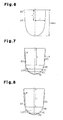
Fig. 6 ] A partially enlarged side view of a valve portion in the electronic expansion valve. - [
Fig. 7 ] A partial side view showing a valve portion according to a modification. - [
Fig. 8 ] A partial side view showing a valve portion according to a modification. - [
Fig. 9 ] A control map used to control the electronic expansion valve. - An air conditioner according to an embodiment of the present invention will be hereinafter described with reference to
Fig. 1 to Fig. 6 . - As shown in
Fig. 1 , theair conditioner 1 is composed of acompressor 10 that compresses a refrigerant, anoutdoor heat exchanger 20 that is disposed outdoors, anelectronic expansion valve 30 that expands a refrigerant, anindoor heat exchanger 50 that is disposed indoors, a four-pass change-overvalve 60, and acontroller 70 that manages and controls each device. - As shown in
Fig. 2 , theelectronic expansion valve 30 is composed of afirst pipe 31 that serves as a gateway for a refrigerant, asecond pipe 32, a rod-shapedvalve body 40, avalve seat 33, acylindrical member 35 that has avalve port 34, and a steppingmotor 36 that drives thevalve body 40 in an axial direction. - The
first pipe 31 serves as one gateway of theelectronic expansion valve 30. Thesecond pipe 32 serves as the other gateway of theelectronic expansion valve 30. Thesecond pipe 32 perpendicularly intersects thefirst pipe 31. Thecylindrical member 35 connects thefirst pipe 31 and avalve chamber 37 together. A taper portion is formed near thevalve chamber 37 of thevalve port 34. The taper portion is a constituent of thevalve seat 33. - As shown in
Fig. 3(a) and Fig. 3(b) , thevalve body 40 is composed of avalve rod 41, ataper portion 42, and avalve portion 43 formed at a forward end of thevalve rod 41 with thetaper portion 42 therebetween. Thevalve rod 41 is fixed to a rotational shaft of the steppingmotor 36. - The
taper portion 42 totally closes theelectronic expansion valve 30 by coming into contact with thevalve seat 33. Thevalve portion 43 is inserted in thevalve port 34. The outer diameter of thevalve portion 43 is smaller than the inner diameter of thevalve port 34, and becomes smaller toward its forward end. A variable throttle portion is formed between thevalve portion 43 and thevalve seat 33 by allowing thevalve portion 43 to move in the axial direction. Thevalve body 40 and the rotational shaft of the steppingmotor 36 are connected together through a rotational conversion mechanism such as screws or gears. The rotational conversion mechanism converts the rotational motion of the rotational shaft of the steppingmotor 36 into the linear motion of thevalve body 40. - The stepping
motor 36 is driven by a pulse signal output from thecontroller 70. A pulse number and a rotation angle correlate with each other. The rotation angle of the rotational shaft of the steppingmotor 36 becomes larger in proportion to the pulse number input to the steppingmotor 36. Thevalve body 40 moves in the axial direction. The movement amount of thevalve body 40 is proportional to the rotation angle of the steppingmotor 36. The movement amount of thevalve body 40, i.e., the movement amount of thevalve portion 43 is proportional to the pulse number output to the steppingmotor 36 from thecontroller 70. - As shown in
Fig. 1 , a temperature sensor 71 and apressure sensor 72 are connected to thecontroller 70. The temperature sensor 71 detects the temperature of a refrigerant (hereinafter, referred to as refrigerant temperature), and outputs a refrigerant temperature signal corresponding to the refrigerant temperature to thecontroller 70. Thepressure sensor 72 detects the pressure of a refrigerant (hereinafter, referred to as refrigerant pressure), and outputs a refrigerant pressure signal corresponding to the refrigerant pressure to thecontroller 70. - The
controller 70 counts a pulse number that is output to the steppingmotor 36. Additionally, thecontroller 70 integrates the counted pulse number, and calculates and stores a pulse integrated value. A positive or negative sign is given to the pulse number. When the rotational shaft of the steppingmotor 36 negatively rotates in a direction in which thevalve portion 43 is inserted into the valve port 34 (hereinafter, referred to as entering direction), the pulse number is a negative value. On the other hand, when the rotational shaft of the steppingmotor 36 positively rotates in a direction in which thevalve portion 43 comes out of the valve port 34 (hereinafter, referred to as leaving direction), the pulse number is a positive value. In other words, when the rotational shaft of the steppingmotor 36 rotates positively and when thevalve portion 43 moves in the leaving direction, the pulse integrated value increases. On the other hand, when the rotational shaft of the steppingmotor 36 rotates negatively and when thevalve portion 43 moves in the entering direction, the pulse integrated value decreases. - As shown in
Fig. 3(a) , the position of thevalve portion 43 located when thetaper portion 42 of thevalve body 40 comes into contact with thevalve seat 33 is set as a reference position. When thevalve portion 43 is in the reference position, the pulse integrated value of thecontroller 70 is reset, and the pulse integrated value becomes "0." As shown inFig. 3(b) , when thevalve portion 43 leaves the reference position, a gap is generated between thevalve portion 43 and a minimum diameter part of thevalve seat 33. The position of thevalve portion 43 is equal to the movement distance of thevalve portion 43 from the reference position. Therefore, the position of thevalve portion 43 is specified by a relationship with the pulse integrated value. The movement amount of thevalve portion 43 from the reference position corresponds to the sum total of the pulse number counted during a movement from the reference position to a predetermined position. The position of thevalve portion 43 corresponds to the pulse integrated value. - The opening area is the area of the gap between the minimum diameter part of the
valve seat 33 and thevalve portion 43. More specifically, the opening area is a difference between the area SA of the minimum diameter part of thevalve seat 33 and the cross-sectional area SB of thevalve portion 43 along a plane including the minimum diameter part of thevalve seat 33. The area SA and the cross-sectional area SB are both equivalent to the area of a cross section perpendicular to the axial direction. - When the whole of the
valve portion 43 appears from thefirst pipe 31, the opening area coincides with the area SA of the minimum diameter part of thevalve seat 33, and corresponds to a maximum opening area Smax. The opening degree is a ratio (%) between the opening area when thevalve portion 43 is in a predetermined position and the maximum opening area Smax. When thetaper portion 42 of thevalve portion 43 and thevalve seat 33 come into contact with each other so as to be totally closed, the opening degree is 0%. When thevalve portion 43 completely appears from thefirst pipe 31, the opening degree is 100%. - The opening degree approximately bears a proportional relationship with the amount of refrigerant flow. When the amount of refrigerant flow is controlled, the opening degree is adjusted. An adjustment to the opening degree is made by use of a pulse integrated value. The opening degree becomes greater in proportion to an increase in the pulse integrated value. On the other hand, an increase aspect of the opening degree resulting from the pulse integrated value depends on a side surface structure of the
valve portion 43. Therefore, when the opening degree is adjusted, thecontroller 70 uses a map showing a relationship between the opening degree and the pulse integrated value. - For example, when the
conical valve portion 43 that has an easily formable shape is employed, a map in which the opening degree is expressed as a C-D·(E-Xa)2 function with respect to the pulse integrated value Xa is used. In this case, a contribution of Xa2 to the opening degree is great when the opening degree is adjusted in a small opening degree range. In other words, the amount of variation of the opening degree in a slight variation of the pulse integrated value Xa is great, and therefore it is difficult to finely adjust the opening degree, and it is difficult to finely adjust the flow rate. Therefore, in the present embodiment, a map that enables an easy opening-degree adjustment is assumed with the aim of controlling the opening degree with high accuracy. Additionally the applicant has devised a valve structure based on this map. - As shown in the map of
Fig. 5(a) , the opening degree becomes great exponentially with respect to the position of thevalve portion 43 corresponding to the pulse integrated value Xa. The opening degree satisfies the following formula (1).
[Numerical Formula 3]
- Y: Opening degree
- A: Constant
- X: Pulse integrated value
- β: Value in which Y = 100 when X = Maximum pulse integrated value Xmax
- Xmax: Maximum value of pulse integrated value, i.e., pulse integrated value corresponding to the position of the
valve portion 43 most distant from the reference position. - When X = 0, i.e., when the pulse integrated value is 0, the opening degree actually becomes 0%. However, for simplification of calculation, let it be assumed that the opening degree has a predetermined value when X = 0.
- According to the opening degree Y(X), the following relation is established in two points that differ by a predetermined value δ of the pulse integrated value X (predetermined increase-decrease value of the pulse number).
[Numerical Formula 4]
- When the predetermined value δ is assumed as 1 (one pulse), the opening degree ratio (Y(X+1)/Y(X)) in two points that differ by 1 in the pulse integrated value X becomes "β." The opening degree ratio is constant regardless of the pulse integrated value X. The opening degree ratio is constant with respect to the pulse integrated value X although the opening degree ratio (Y(X+δ)/Y(X)) also becomes great when the predetermined value δ is made great.
- In short, the fact that Formula (1) is satisfied is the same as the fact that Formula (2) is satisfied. If a map that satisfies Formula (1) is used, the opening degree ratio will become constant with respect to the position of the
valve portion 43 corresponding to the pulse integrated value. When the opening degree ratio is constant over the whole of the pulse integrated value, the variation ratio of the amount of refrigerant flow with respect to the pulse integrated value also becomes constant. Therefore, it is easy to control the amount of refrigerant flow. The opening degree particularly in a small opening degree range increases little by little, and therefore it becomes possible to finely adjust the amount of refrigerant flow. - The fact that the opening degree ratio is constant denotes the fact that the opening degree increases in predetermined-value increments with respect to an increment of the pulse integrated value. For example, when the opening degree ratio is 1.05 and when the initial value of the opening degree is 1 %, the opening degree sequentially increases in increments of 1.0%, 1.05%, 1.1025%, 1.15763%, and so on with respect to an increase in the pulse integrated value in increments of 1.
- According to this type of map, the amount of refrigerant flow increases exponentially with an increase in the pulse integrated value. In other words, when the pulse integrated value is small, the amount of refrigerant flow is small, and an increment of the amount of refrigerant flow resulting from an increase in the pulse integrated value is also small. On the other hand, when the pulse integrated value is great, the amount of refrigerant flow is great, and an increment of the amount of refrigerant flow resulting from an increase in the pulse integrated value is also great.
- With reference to
Fig. 6 , a description will be given of the shape of a visible outline of thevalve portion 43 that satisfies Formula (1). The visible outline of a cross section including a valve axis of thevalve portion 43 satisfies the following formulas.
[Numerical Formula 5]
[Numerical Formula 6]
- x: Length from a
basal part 44 to a part corresponding to the radius r in thevalve portion 43 - xmax: Length from the
basal part 44 to the forward end in thevalve portion 43 - β: Opening degree ratio
- Smax: Maximum opening area
- r: Length (radius) from the valve axis of the
valve portion 43 to the side surface - B: Constant.
- When a distance by which the
valve portion 43 moves in the axial direction per one pulse is set as a unit distance, xmax corresponds to the product of the unit distance and the maximum pulse integrated value Xmax. Additionally, the width of thetaper portion 42 is assumed as being extremely small, and the cross-sectional area of thebasal part 44 and the maximum opening area Smax are assumed as coinciding with each other. - The
valve portion 43 that satisfies the aforementioned formulas satisfies Formula (1) and Formula (2) by means of pulse driving. According to Formula (3), Formula (5) is established.
[Numerical Formula 7]
- Formula (5) shows a relationship between r and the distance x when the
valve portion 43 is separated from the reference position to the position of the distance x. Formula (5) shows the opening area. Formula (5) shows the opening degree at a predetermined position of thevalve portion 43. According to Formula (5), a difference between the maximum opening area Smax and the cross-sectional area (π·r2) of thevalve portion 43 along a plane including a minimum diameter part of thevalve seat 33 is expressed as an exponential function of the position of the valve portion. Formula (5) is the same as Formula (1). In Formula (4), the opening degree ratio is constant regardless of the position of thevalve portion 43. - Another example of the
valve portion 43 will be described with reference toFig. 7 . A side surface of thevalve portion 43 of this example is divided into five regions. A first region RA corresponds to a part in which the opening degree is from 0% to less than 20%. A second region RB corresponds to a part in which the opening degree is from 20% to less than 40%. A third region RC corresponds to a part in which the opening degree is from 40% to less than 60%. A fourth region RD corresponds to a part in which the opening degree is from 60% to less than 80%. A fifth region RE corresponds to a part in which the opening degree is from 80% to 100%. - A side surface of each region is a side surface shaped in a truncated cone. A borderline LS of the side surface of each region is disposed on a virtual curved surface V in which the opening degree ratio becomes constant. More specifically, the virtual curved surface V is a curved surface that satisfies Formula (3) and Formula (4). The side surface of the
valve portion 43 is approximated to the virtual curved surface V. In this case, an interval length L that is a length in the axial direction of each region becomes smaller toward the forward end of thevalve portion 43 in order of disposition. An angle θ of the side surface of the first region RA satisfies the relation 0 < tanθ < 0.2 with respect to the valve axis of thevalve portion 43. - Another example of the
valve portion 43 will be described with reference toFig. 8 . A side surface of thevalve portion 43 of this example is divided into four regions. A first region RA corresponds to a part in which the opening degree is from 0% to less than 25%. A second region RB corresponds to a part in which the opening degree is from 25% to less than 50%. A third region RC corresponds to a part in which the opening degree is from 50% to less than 75%. A fourth region RD corresponds to a part in which the opening degree is from 75% to 100%. - A side surface of each region is a side surface shaped in a truncated cone. A borderline LS of the side surface of each region is disposed on a virtual curved surface V in which the opening degree ratio becomes constant. More specifically, the virtual curved surface V is a curved surface that satisfies Formula (3) and Formula (4). The side surface of the
valve portion 43 is approximated to the virtual curved surface V. In this case, an interval length L that is a length in the axial direction of each region becomes smaller toward the forward end of thevalve portion 43 in order of disposition. An angle θ of the side surface of the first region RA satisfies the relation 0 <tanθ < 0.2 with respect to the valve axis of thevalve portion 43. - Next, control of the amount of refrigerant flow will be described. In the
air conditioner 1, the amount of refrigerant flow is adjusted based on refrigerant pressure, refrigerant temperature, etc. The amount of refrigerant flow is adjusted by adjusting the opening degree of theelectronic expansion valve 30. A required opening degree is calculated by thecontroller 70 based on refrigerant pressure, refrigerant temperature, etc. The opening degree of theelectronic expansion valve 30 is adjusted to correspond to the required opening degree. The required opening degree is updated by PID control one after another, and is adjusted each time. - After determining the required opening degree, the
controller 70 makes an adjustment so that the opening degree of theelectronic expansion valve 30 coincides with the required opening degree. More specifically, thecontroller 70 determines a correction pulse value that is a pulse integrated value corresponding to the required opening degree while using a control map. Thereafter, thecontroller 70 reads an actual pulse value that is a pulse integrated value when the required opening degree is commanded, and a difference between the correction pulse value and the actual pulse value is calculated. Thereafter, thecontroller 70 outputs a pulse signal corresponding to this difference to the steppingmotor 36 and drives thevalve portion 43. Thecontroller 70 thus allows the opening degree of theelectronic expansion valve 30 to coincide with the required opening degree. - Next, the control map will be described with reference to
Fig. 9 . The control map ofFig. 9 is substantially the same as the map ofFig. 5(a) . In the control map, the opening degree ratio becomes constant regardless of the magnitude of the pulse integrated value. Herein, the abscissa axis indicates required opening degrees, and the ordinate axis indicates pulse integrated values. - Next, a description will be given of a control map relative to the
electronic expansion valve 30 of the present embodiment in comparison with an electronic expansion valve having a conventional structure. The broken line ofFig. 9 shows a control map of an electronic expansion valve having a conventional structure. The conventionally structured electronic expansion valve has a valve portion shaped in a cone or a truncated cone. In this type of valve portion, the opening degree becomes greater in proportion to the square of the movement amount of the valve portion when the valve portion moves in a direction coming out of the valve port in accordance with a pulse integrated value. Therefore, it is difficult to change the required opening degree little by little when the required opening degree is small. As shown inFig. 9 , the pulse integrated value corresponding to a small opening degree range that is from 0% to 10% of the required opening degree is 1/10 or less of the maximum pulse integrated value. - On the other hand, in the
electronic expansion valve 30 of the present embodiment, the opening degree is arranged so as to increase exponentially. Therefore, as shown inFig. 9 , the pulse integrated value corresponding to the small opening degree range occupies about 1/2 of the maximum pulse integrated value. Therefore, in the small opening degree range, thevalve portion 43 can be controlled by use of pulse numbers more than in the conventional structure, and the opening degree can be finely adjusted. As a result, the amount of refrigerant flow can be controlled highly accurately. - As described below, according to the present embodiment, the following effects can be achieved.
- (1) The opening degree ratio is constant when a gap is formed between the side surface of the
valve portion 43 and thevalve seat 33. According to this arrangement, the side surface of thevalve portion 43 is formed as above, and therefore the opening area increases at a fixed ratio when thevalve portion 43 is moved. Therefore, the variation ratio of the amount of refrigerant flow becomes constant. Therefore, the amount of refrigerant flow can be finely adjusted. - (2) The side surface of the
valve portion 43 is divided into three or more regions in the axial direction. Additionally, the borderline of each region is disposed on the virtual curved surface V in which the opening degree ratio becomes constant. According to this arrangement, the side surface of each region is formed on and along the virtual curved surface V. In other words, the side surface of thevalve portion 43 is approximated to the virtual curved surface V. As a result, the variation ratio of the amount of refrigerant flow becomes substantially constant over the moving range of thevalve portion 43. Therefore, the amount of refrigerant flow can be finely adjusted. - (3) In the modification shown in
Fig. 7 , the interval length L of each region of the side surface of the valve portion becomes smaller toward the forward end of thevalve portion 43 in order of disposition. According to this arrangement, the amount of variation with respect to the movement amount of thevalve portion 43 becomes greater in proportion to an increase in the opening degree, and becomes smaller in proportion to a decrease in the opening degree. In other words, in a small opening degree range, the amount of refrigerant flow can be adjusted with higher accuracy than in a large opening degree range. Additionally, thevalve portion 43 can be made shorter than in an arrangement in which the interval length L of each region does not become smaller toward the forward end of thevalve portion 43 in order of disposition. - (4) The visible outline of a cross section including the valve axis of the
valve portion 43 satisfies the relation shown in Formula (3) and Formula (4). According to this arrangement, the side surface is formed with a curved surface, and the opening degree ratio is β in the moving range of thevalve portion 43. Therefore, a variation in the flow rate of a refrigerant can be made substantially constant over the moving range of thevalve portion 43. - (5) In the modification shown in
Fig. 8 , the aspect of the side surface of thevalve portion 43 varies whenever thevalve portion 43 moves and the opening degree increases by 25%. Additionally, each borderline is disposed on the virtual curved surface V in which the opening degree ratio becomes constant. Therefore, thevalve portion 43 can be more easily formed than in a case in which the side surface of thevalve portion 43 is a curved surface. Additionally, the flow-rate variation ratio can be made substantially constant over the moving range of thevalve portion 43. - (6) In the modification shown in
Fig. 8 , the aspect of the side surface of thevalve portion 43 varies whenever thevalve portion 43 moves and the opening degree increases by 20%. Additionally, each borderline is disposed on the virtual curved surface V in which the opening degree ratio becomes constant. Therefore, thevalve portion 43 can be more easily formed than in a case in which the side surface of thevalve portion 43 is a curved surface. Additionally the flow-rate variation ratio can be made substantially constant over the moving range of thevalve portion 43. - (7) The angle θ of the side surface of the first region satisfies the relation 0 < tanθ < 0.2 with respect to the valve axis of the
valve portion 43. In this case, the opening area can be increased and decreased little by little with respect to the movement of thevalve portion 43. Therefore, the amount of refrigerant flow can be finely adjusted in a small opening degree range. - (8) The
air conditioner 1 is provided with theelectronic expansion valve 30. According to this arrangement, the amount of refrigerant flow can be finely adjusted, and therefore air-conditioning performance by means of theair conditioner 1 is stabilized. - The present mode can be modified as follows.
- Although the entire side surface of the
valve portion 43 satisfies Formula (3) and Formula (4) in the present embodiment, only a part of the side surface may satisfy Formula (3) and Formula (4). In this case, the opening ratio in at least one part of the side surface of thevalve portion 43 becomes constant. Therefore, in the part satisfying Formulas (3) and (4) of the side surface of thevalve portion 43, the amount of refrigerant flow can be controlled with high accuracy. - For example, if the length from the
basal part 44 to the forward end of thevalve portion 43 is set as 100 and if the position of the basal part is set as 0, Formula (3) and Formula (4) may be satisfied in the range of 1 to 25. The fact that the opening degree ratio is made constant only in a predetermined region denotes that the flow rate is almost zero in the position 0, and has a technical meaning when the opening degree is not controlled in a minimum opening degree range or when a fine adjustment of the opening degree is less frequently made in the range of 25 to 100 in the position. - Although the shape of the side surface of the
valve portion 43 is optimized as achieved in the map of Formula (1) in the present embodiment, the shape of the valve seat may be optimized instead of the shape of the side surface of thevalve portion 43. Additionally both the shape of thevalve portion 43 and the shape of thevalve seat 33 may be optimized as achieved in the map of Formula (1). - Although the side surface of the
valve portion 43 is divided into five or four surface parts in each modification shown inFigs. 7 and 8 , it may be divided into six or more surface parts or may be divided into three surface parts. In any case, a polyhedron consisting of surfaces of each region is formed so that the entire side surface of thevalve portion 43 expands with respect to a virtual conical shape composed of a bottom surface and a forward end of thevalve portion 43.
Claims (8)
- An electronic expansion valve comprising:a valve body whose forward end is provided with a valve portion;a valve seat that forms a variable throttle portion between the valve portion and the valve seat by allowing the valve body to move in an axial direction; anda stepping motor that moves the valve body in accordance with a pulse number,wherein when an area of a cross section of a gap formed between the valve portion and the valve seat and that is perpendicular to the axial direction is defined as an opening area and when an area ratio between the opening area in which the pulse number has not yet been increased and decreased and the opening area in which the pulse number has already been increased and decreased is defined as an opening degree ratio, at least one part of a side surface of the valve portion is shaped so that the opening degree ratio becomes constant.
- The electronic expansion valve according to claim 1, wherein the side surface of the valve portion is divided into three or more regions in the axial direction, and a borderline of each of the regions is disposed on a virtual curved surface in which the opening degree ratio becomes constant.
- The electronic expansion valve according to claim 2, wherein when a length in the axial direction of each of the regions is defined as an interval length, the interval length of each region becomes smaller toward a forward end of the valve portion in order of disposition of the regions.
- The electronic expansion valve according to any one of claim 1 to claim 3, wherein when a maximum value of the opening area is defined as a maximum opening area and when a percentage of the opening area with respect to the maximum opening area is defined as an opening degree, the side surface of the valve portion is divided into:a first region that corresponds to a part in which the opening degree is from 0% to less than 25%;a second region that corresponds to a part in which the opening degree is from 25% to less than 50%;a third region that corresponds to a part in which the opening degree is from 50% to less than 75%; anda fourth region that corresponds to a part in which the opening degree is from 75% to 100%, andwherein the side surface of each region is a side surface shaped in a truncated cone, and the borderline of each region is disposed on a virtual curved surface in which the opening degree ratio becomes constant.
- The electronic expansion valve according to any one of claim 1 to claim 3, wherein when a maximum value of the opening area is defined as a maximum opening area and when a percentage of the opening area with respect to the maximum opening area is defined as an opening degree, the side surface of the valve portion is divided into:a first region that corresponds to a part in which the opening degree is from 0% to less than 20%;a second region that corresponds to a part in which the opening degree is from 20% to less than 40%;a third region that corresponds to a part in which the opening degree is from 40% to less than 60%;a fourth region that corresponds to a part in which the opening degree is from 60% to less than 80%; anda fifth region that corresponds to a part in which the opening degree is from 80% to 100%, andwherein the side surface of each region is a side surface shaped in a truncated cone, and the borderline of each region is disposed on a virtual curved surface in which the opening degree ratio becomes constant.
- The electronic expansion valve according to claim 1, wherein a visible outline of a cross section including a valve axis of the valve portion satisfies a relation expressed by the two following formulas:

(wherein x is a length from a basal part of the valve seat to a part corresponding to radius r in the axial direction of the valve portion, xmax is a length from the basal part to the forward end of the valve portion, β is an opening degree ratio, Smax is a maximum opening area, and r is a length (radius) from the valve axis to the side surface of the valve portion). - An electronic expansion valve comprising:a valve body whose forward end is provided with a valve portion;a valve seat that forms a variable throttle portion between the valve portion and the valve seat by allowing the valve body to move in an axial direction; anda stepping motor that moves the valve body in accordance with a pulse number, wherein, in a region at least from the basal part to 1/5 of an interval between the basal part and the forward end of the side surface of the valve portion, an angle θ with respect to the valve axis of the valve portion satisfies the following formula:

- An air conditioner including the electronic expansion valve according to any one of claim 1 to claim 7.
Applications Claiming Priority (2)
| Application Number | Priority Date | Filing Date | Title |
|---|---|---|---|
| JP2011252738A JP2013108647A (en) | 2011-11-18 | 2011-11-18 | Electronic expansion valve and air conditioner |
| PCT/JP2012/079417 WO2013073531A1 (en) | 2011-11-18 | 2012-11-13 | Electronic expansion valve, and air conditioner |
Publications (3)
| Publication Number | Publication Date |
|---|---|
| EP2781859A1 true EP2781859A1 (en) | 2014-09-24 |
| EP2781859A4 EP2781859A4 (en) | 2015-05-27 |
| EP2781859B1 EP2781859B1 (en) | 2018-01-03 |
Family
ID=48429588
Family Applications (1)
| Application Number | Title | Priority Date | Filing Date |
|---|---|---|---|
| EP12849516.5A Active EP2781859B1 (en) | 2011-11-18 | 2012-11-13 | Electronic expansion valve, and air conditioner |
Country Status (9)
| Country | Link |
|---|---|
| US (1) | US9513040B2 (en) |
| EP (1) | EP2781859B1 (en) |
| JP (1) | JP2013108647A (en) |
| KR (1) | KR101653893B1 (en) |
| CN (1) | CN103946651B (en) |
| AU (1) | AU2012337824B2 (en) |
| ES (1) | ES2658187T3 (en) |
| IN (1) | IN2014KN01080A (en) |
| WO (1) | WO2013073531A1 (en) |
Cited By (3)
| Publication number | Priority date | Publication date | Assignee | Title |
|---|---|---|---|---|
| EP3462064A1 (en) | 2015-11-17 | 2019-04-03 | Fujikoki Corporation | Flow control valve |
| US12072039B2 (en) | 2018-12-20 | 2024-08-27 | Danfoss A/S | Electric expansion valve |
| US12117215B2 (en) | 2018-12-20 | 2024-10-15 | Danfoss A/S | Valve having a motor arranged inside a tube having sections with different diameters |
Families Citing this family (22)
| Publication number | Priority date | Publication date | Assignee | Title |
|---|---|---|---|---|
| ITMI20130583A1 (en) * | 2013-04-11 | 2014-10-12 | Frascold S P A | COMPRESSOR FOR A REFRIGERATOR SYSTEM AND REFRIGERATING SYSTEM INCLUDING THE COMPRESSOR |
| JP6143651B2 (en) * | 2013-11-14 | 2017-06-07 | 愛三工業株式会社 | Exhaust gas recirculation valve |
| JP6446468B2 (en) * | 2014-03-19 | 2018-12-26 | 浙江三花智能控制股▲分▼有限公司 | Electronic expansion valve |
| CN103940159B (en) * | 2014-03-25 | 2017-08-29 | 浙江三花智能控制股份有限公司 | A kind of electric expansion valve |
| US10401065B2 (en) * | 2014-10-08 | 2019-09-03 | Mitsubishi Electric Corporation | Expansion valve, and refrigeration cycle system using expansion valve |
| JP6566693B2 (en) * | 2015-04-03 | 2019-08-28 | 日立ジョンソンコントロールズ空調株式会社 | Refrigeration cycle equipment |
| CN105972233A (en) * | 2016-07-20 | 2016-09-28 | 珠海格力电器股份有限公司 | Expansion valve, refrigerant circulation system and air conditioner |
| CN106151643B (en) * | 2016-08-18 | 2018-07-06 | 深圳市共济科技股份有限公司 | A kind of electrical ball valve aperture control method and system |
| CN106369893A (en) * | 2016-11-21 | 2017-02-01 | 珠海格力电器股份有限公司 | Air conditioner and electronic expansion valve thereof |
| CN108361393B (en) * | 2017-01-26 | 2021-08-27 | 浙江三花智能控制股份有限公司 | Electronic expansion valve |
| WO2018137636A1 (en) | 2017-01-26 | 2018-08-02 | 浙江三花智能控制股份有限公司 | Electronic expansion valve |
| WO2018143040A1 (en) * | 2017-01-31 | 2018-08-09 | 株式会社フジキン | Flow dividing valve |
| US20190178545A1 (en) * | 2017-12-07 | 2019-06-13 | Dunan Microstaq, Inc. | Heating, ventilating, air conditioning, and refrigeration system with mass flow stabilization |
| KR101879154B1 (en) * | 2018-02-08 | 2018-07-17 | 장상훈 | Management system for watertight and gastight of vessel |
| CN110397759B (en) * | 2018-04-25 | 2020-10-27 | 杭州三花研究院有限公司 | Throttle device |
| KR102597661B1 (en) * | 2019-06-28 | 2023-11-03 | 쯔지앙 산화 인텔리전트 컨트롤스 씨오., 엘티디. | Electronic expansion valve |
| JP7134146B2 (en) * | 2019-07-26 | 2022-09-09 | 株式会社鷺宮製作所 | Expansion valve and refrigeration cycle system |
| WO2021050767A1 (en) | 2019-09-12 | 2021-03-18 | Relievant Medsystems, Inc. | Systems and methods for tissue modulation |
| CN114352730A (en) * | 2020-10-12 | 2022-04-15 | 浙江盾安人工环境股份有限公司 | Flow regulating valve |
| CN216158328U (en) * | 2021-09-02 | 2022-04-01 | 苏州华越金属有限公司 | Valve needle and electronic expansion valve having the same |
| CN115931341B (en) * | 2022-12-13 | 2025-12-12 | 金坤建设集团有限公司 | A method, system, equipment, and medium for detecting the opening degree of a control valve. |
| CN115899372A (en) * | 2022-12-31 | 2023-04-04 | 浙江青科质谱仪器创新有限公司 | Valve with throttling function and its working method |
Citations (7)
| Publication number | Priority date | Publication date | Assignee | Title |
|---|---|---|---|---|
| JPH0471008A (en) | 1990-07-11 | 1992-03-05 | Noritz Corp | Flow rate adjustor and its using method |
| JPH0683946U (en) | 1993-05-17 | 1994-12-02 | エヌオーケー株式会社 | Needle valve |
| JPH10148420A (en) | 1996-11-18 | 1998-06-02 | Toshiba Corp | Air conditioner |
| JP2002122258A (en) | 2000-10-11 | 2002-04-26 | Matsushita Refrig Co Ltd | Electric control valve and method of assembling the same |
| JP2005155878A (en) | 2003-11-28 | 2005-06-16 | Asahi Organic Chem Ind Co Ltd | Flow rate adjustment valve |
| JP2006052807A (en) | 2004-08-13 | 2006-02-23 | Saginomiya Seisakusho Inc | Rotary flow control valve and refrigeration cycle device |
| JP2011252738A (en) | 2010-06-01 | 2011-12-15 | Shimadzu Corp | Signal processing device for pulse measurement |
Family Cites Families (7)
| Publication number | Priority date | Publication date | Assignee | Title |
|---|---|---|---|---|
| US2863473A (en) * | 1955-02-28 | 1958-12-09 | Vincent W Eckel | Balanced valve |
| JP2898906B2 (en) * | 1995-06-29 | 1999-06-02 | 株式会社不二工機 | Electric flow control valve |
| US5675982A (en) * | 1996-04-26 | 1997-10-14 | Rocky Research | Pulsed operation control valve |
| JPH10160034A (en) * | 1996-11-22 | 1998-06-16 | Nok Corp | Needle valve |
| JP2000193101A (en) * | 1998-12-25 | 2000-07-14 | Fuji Koki Corp | Flow control valve |
| JP4749784B2 (en) | 2005-07-19 | 2011-08-17 | 株式会社不二工機 | Motorized valve |
| JP5249634B2 (en) * | 2008-05-29 | 2013-07-31 | 株式会社不二工機 | Flow control valve |
-
2011
- 2011-11-18 JP JP2011252738A patent/JP2013108647A/en active Pending
-
2012
- 2012-11-13 WO PCT/JP2012/079417 patent/WO2013073531A1/en not_active Ceased
- 2012-11-13 EP EP12849516.5A patent/EP2781859B1/en active Active
- 2012-11-13 CN CN201280056240.2A patent/CN103946651B/en active Active
- 2012-11-13 AU AU2012337824A patent/AU2012337824B2/en active Active
- 2012-11-13 KR KR1020147011159A patent/KR101653893B1/en active Active
- 2012-11-13 US US14/352,759 patent/US9513040B2/en active Active
- 2012-11-13 ES ES12849516.5T patent/ES2658187T3/en active Active
- 2012-11-13 IN IN1080KON2014 patent/IN2014KN01080A/en unknown
Patent Citations (7)
| Publication number | Priority date | Publication date | Assignee | Title |
|---|---|---|---|---|
| JPH0471008A (en) | 1990-07-11 | 1992-03-05 | Noritz Corp | Flow rate adjustor and its using method |
| JPH0683946U (en) | 1993-05-17 | 1994-12-02 | エヌオーケー株式会社 | Needle valve |
| JPH10148420A (en) | 1996-11-18 | 1998-06-02 | Toshiba Corp | Air conditioner |
| JP2002122258A (en) | 2000-10-11 | 2002-04-26 | Matsushita Refrig Co Ltd | Electric control valve and method of assembling the same |
| JP2005155878A (en) | 2003-11-28 | 2005-06-16 | Asahi Organic Chem Ind Co Ltd | Flow rate adjustment valve |
| JP2006052807A (en) | 2004-08-13 | 2006-02-23 | Saginomiya Seisakusho Inc | Rotary flow control valve and refrigeration cycle device |
| JP2011252738A (en) | 2010-06-01 | 2011-12-15 | Shimadzu Corp | Signal processing device for pulse measurement |
Non-Patent Citations (4)
| Title |
|---|
| "Cavitation and erosion in control valves by pressure reduction and flow regulation of high pressure liquid", WASEDA UNIVERSITY DOCTORIAL THESIS, March 2003 (2003-03-01) |
| "Characteristics of Ratio Control Systems with a Fuel Control Device Directly Connected to an Air Flow Metering Element", TRANSACTIONS OF THE JAPAN SOCIETY OF MECHANICAL ENGINEERES, vol. 53, no. 487, 1987, pages 739 - 743 |
| SATOSHI YUZAWA: "CAVITATION AND EROSION IN CONTROL VALVES BY PRESSURE REDUCTION AND FLOW REGULATION OF HIGH PRESSURE LIQUID", ABSTARCT OF DOCTORAL THESIS, March 2003 (2003-03-01), pages 1 - 5, XP003035381 |
| See also references of WO2013073531A1 |
Cited By (4)
| Publication number | Priority date | Publication date | Assignee | Title |
|---|---|---|---|---|
| EP3462064A1 (en) | 2015-11-17 | 2019-04-03 | Fujikoki Corporation | Flow control valve |
| EP3462064B1 (en) * | 2015-11-17 | 2021-11-10 | Fujikoki Corporation | Flow control valve |
| US12072039B2 (en) | 2018-12-20 | 2024-08-27 | Danfoss A/S | Electric expansion valve |
| US12117215B2 (en) | 2018-12-20 | 2024-10-15 | Danfoss A/S | Valve having a motor arranged inside a tube having sections with different diameters |
Also Published As
| Publication number | Publication date |
|---|---|
| EP2781859A4 (en) | 2015-05-27 |
| EP2781859B1 (en) | 2018-01-03 |
| US20140283546A1 (en) | 2014-09-25 |
| US9513040B2 (en) | 2016-12-06 |
| CN103946651A (en) | 2014-07-23 |
| AU2012337824B2 (en) | 2015-11-26 |
| CN103946651B (en) | 2017-07-28 |
| JP2013108647A (en) | 2013-06-06 |
| WO2013073531A1 (en) | 2013-05-23 |
| KR101653893B1 (en) | 2016-09-02 |
| ES2658187T3 (en) | 2018-03-08 |
| IN2014KN01080A (en) | 2015-10-09 |
| AU2012337824A1 (en) | 2014-04-24 |
| KR20140082744A (en) | 2014-07-02 |
Similar Documents
| Publication | Publication Date | Title |
|---|---|---|
| US9513040B2 (en) | Electronic expansion valve, and air conditioner | |
| RU2640707C2 (en) | Method of adjustment of air conditioner blinds | |
| JP5395775B2 (en) | Motorized valve | |
| US20070218827A1 (en) | Variable air volume control apparatus | |
| AU2007223216B2 (en) | Freezer heat exchanger coolant flow divider | |
| EP3282198B1 (en) | Air conditioner | |
| MX2007013811A (en) | A field adjustable control valve assembly and field adjustment module. | |
| JP2014081046A (en) | Flow rate control valve | |
| US20150167660A1 (en) | Fluid valve | |
| CN105782036A (en) | Compressor and internal volume ratio adjusting method for compressor | |
| CN201302259Y (en) | Gas flow control device | |
| CN106679247B (en) | Electronic expansion valve of air conditioning system for vehicle | |
| JPH0689741B2 (en) | Capacity control valve | |
| US20090138129A1 (en) | Freezer Heat Exchanger Coolant Flow Divider Control Device | |
| US20200340464A1 (en) | Control Device For A Compressor, A Compressor With The Same, And An Air Conditioning System Including Control Device And Compressor | |
| JP2014047853A (en) | Control method of actuator for valve and ball valve with actuator | |
| CN111022736B (en) | Evaporating pressure regulating valve capable of electrically regulating pressure | |
| CN211231717U (en) | Air volume adjusting device with internal valve | |
| RU2564589C2 (en) | Gas-dynamic method of self-regulation of air flow in ventilation system | |
| JP7006979B2 (en) | Solenoid valve | |
| CN202545858U (en) | Electromagnetic expansion valve | |
| US20250092955A1 (en) | Circulation valve and air conditioner | |
| CN214699222U (en) | Elastic balance type electronic expansion valve with large-caliber on-off function | |
| CN220567361U (en) | Fresh air device, air conditioner indoor unit and air conditioner | |
| JPH04167110A (en) | Hot/cold water mixing device |
Legal Events
| Date | Code | Title | Description |
|---|---|---|---|
| PUAI | Public reference made under article 153(3) epc to a published international application that has entered the european phase |
Free format text: ORIGINAL CODE: 0009012 |
|
| 17P | Request for examination filed |
Effective date: 20140404 |
|
| AK | Designated contracting states |
Kind code of ref document: A1 Designated state(s): AL AT BE BG CH CY CZ DE DK EE ES FI FR GB GR HR HU IE IS IT LI LT LU LV MC MK MT NL NO PL PT RO RS SE SI SK SM TR |
|
| TPAC | Observations filed by third parties |
Free format text: ORIGINAL CODE: EPIDOSNTIPA |
|
| DAX | Request for extension of the european patent (deleted) | ||
| RA4 | Supplementary search report drawn up and despatched (corrected) |
Effective date: 20150428 |
|
| RIC1 | Information provided on ipc code assigned before grant |
Ipc: F16K 31/04 20060101ALI20150421BHEP Ipc: F16K 1/36 20060101ALI20150421BHEP Ipc: F25B 41/06 20060101AFI20150421BHEP |
|
| TPAC | Observations filed by third parties |
Free format text: ORIGINAL CODE: EPIDOSNTIPA |
|
| GRAP | Despatch of communication of intention to grant a patent |
Free format text: ORIGINAL CODE: EPIDOSNIGR1 |
|
| STAA | Information on the status of an ep patent application or granted ep patent |
Free format text: STATUS: GRANT OF PATENT IS INTENDED |
|
| INTG | Intention to grant announced |
Effective date: 20170906 |
|
| GRAS | Grant fee paid |
Free format text: ORIGINAL CODE: EPIDOSNIGR3 |
|
| GRAA | (expected) grant |
Free format text: ORIGINAL CODE: 0009210 |
|
| STAA | Information on the status of an ep patent application or granted ep patent |
Free format text: STATUS: THE PATENT HAS BEEN GRANTED |
|
| AK | Designated contracting states |
Kind code of ref document: B1 Designated state(s): AL AT BE BG CH CY CZ DE DK EE ES FI FR GB GR HR HU IE IS IT LI LT LU LV MC MK MT NL NO PL PT RO RS SE SI SK SM TR |
|
| REG | Reference to a national code |
Ref country code: GB Ref legal event code: FG4D |
|
| REG | Reference to a national code |
Ref country code: CH Ref legal event code: EP Ref country code: AT Ref legal event code: REF Ref document number: 960665 Country of ref document: AT Kind code of ref document: T Effective date: 20180115 |
|
| REG | Reference to a national code |
Ref country code: IE Ref legal event code: FG4D |
|
| REG | Reference to a national code |
Ref country code: DE Ref legal event code: R096 Ref document number: 602012041694 Country of ref document: DE |
|
| REG | Reference to a national code |
Ref country code: ES Ref legal event code: FG2A Ref document number: 2658187 Country of ref document: ES Kind code of ref document: T3 Effective date: 20180308 |
|
| REG | Reference to a national code |
Ref country code: NL Ref legal event code: MP Effective date: 20180103 |
|
| REG | Reference to a national code |
Ref country code: LT Ref legal event code: MG4D |
|
| REG | Reference to a national code |
Ref country code: AT Ref legal event code: MK05 Ref document number: 960665 Country of ref document: AT Kind code of ref document: T Effective date: 20180103 |
|
| PG25 | Lapsed in a contracting state [announced via postgrant information from national office to epo] |
Ref country code: NL Free format text: LAPSE BECAUSE OF FAILURE TO SUBMIT A TRANSLATION OF THE DESCRIPTION OR TO PAY THE FEE WITHIN THE PRESCRIBED TIME-LIMIT Effective date: 20180103 |
|
| PG25 | Lapsed in a contracting state [announced via postgrant information from national office to epo] |
Ref country code: FI Free format text: LAPSE BECAUSE OF FAILURE TO SUBMIT A TRANSLATION OF THE DESCRIPTION OR TO PAY THE FEE WITHIN THE PRESCRIBED TIME-LIMIT Effective date: 20180103 Ref country code: CY Free format text: LAPSE BECAUSE OF FAILURE TO SUBMIT A TRANSLATION OF THE DESCRIPTION OR TO PAY THE FEE WITHIN THE PRESCRIBED TIME-LIMIT Effective date: 20180103 Ref country code: LT Free format text: LAPSE BECAUSE OF FAILURE TO SUBMIT A TRANSLATION OF THE DESCRIPTION OR TO PAY THE FEE WITHIN THE PRESCRIBED TIME-LIMIT Effective date: 20180103 Ref country code: NO Free format text: LAPSE BECAUSE OF FAILURE TO SUBMIT A TRANSLATION OF THE DESCRIPTION OR TO PAY THE FEE WITHIN THE PRESCRIBED TIME-LIMIT Effective date: 20180403 Ref country code: HR Free format text: LAPSE BECAUSE OF FAILURE TO SUBMIT A TRANSLATION OF THE DESCRIPTION OR TO PAY THE FEE WITHIN THE PRESCRIBED TIME-LIMIT Effective date: 20180103 |
|
| PG25 | Lapsed in a contracting state [announced via postgrant information from national office to epo] |
Ref country code: BG Free format text: LAPSE BECAUSE OF FAILURE TO SUBMIT A TRANSLATION OF THE DESCRIPTION OR TO PAY THE FEE WITHIN THE PRESCRIBED TIME-LIMIT Effective date: 20180403 Ref country code: IS Free format text: LAPSE BECAUSE OF FAILURE TO SUBMIT A TRANSLATION OF THE DESCRIPTION OR TO PAY THE FEE WITHIN THE PRESCRIBED TIME-LIMIT Effective date: 20180503 Ref country code: AT Free format text: LAPSE BECAUSE OF FAILURE TO SUBMIT A TRANSLATION OF THE DESCRIPTION OR TO PAY THE FEE WITHIN THE PRESCRIBED TIME-LIMIT Effective date: 20180103 Ref country code: LV Free format text: LAPSE BECAUSE OF FAILURE TO SUBMIT A TRANSLATION OF THE DESCRIPTION OR TO PAY THE FEE WITHIN THE PRESCRIBED TIME-LIMIT Effective date: 20180103 Ref country code: SE Free format text: LAPSE BECAUSE OF FAILURE TO SUBMIT A TRANSLATION OF THE DESCRIPTION OR TO PAY THE FEE WITHIN THE PRESCRIBED TIME-LIMIT Effective date: 20180103 Ref country code: RS Free format text: LAPSE BECAUSE OF FAILURE TO SUBMIT A TRANSLATION OF THE DESCRIPTION OR TO PAY THE FEE WITHIN THE PRESCRIBED TIME-LIMIT Effective date: 20180103 Ref country code: GR Free format text: LAPSE BECAUSE OF FAILURE TO SUBMIT A TRANSLATION OF THE DESCRIPTION OR TO PAY THE FEE WITHIN THE PRESCRIBED TIME-LIMIT Effective date: 20180404 Ref country code: PL Free format text: LAPSE BECAUSE OF FAILURE TO SUBMIT A TRANSLATION OF THE DESCRIPTION OR TO PAY THE FEE WITHIN THE PRESCRIBED TIME-LIMIT Effective date: 20180103 |
|
| REG | Reference to a national code |
Ref country code: DE Ref legal event code: R097 Ref document number: 602012041694 Country of ref document: DE |
|
| REG | Reference to a national code |
Ref country code: FR Ref legal event code: PLFP Year of fee payment: 7 |
|
| PG25 | Lapsed in a contracting state [announced via postgrant information from national office to epo] |
Ref country code: EE Free format text: LAPSE BECAUSE OF FAILURE TO SUBMIT A TRANSLATION OF THE DESCRIPTION OR TO PAY THE FEE WITHIN THE PRESCRIBED TIME-LIMIT Effective date: 20180103 Ref country code: RO Free format text: LAPSE BECAUSE OF FAILURE TO SUBMIT A TRANSLATION OF THE DESCRIPTION OR TO PAY THE FEE WITHIN THE PRESCRIBED TIME-LIMIT Effective date: 20180103 Ref country code: AL Free format text: LAPSE BECAUSE OF FAILURE TO SUBMIT A TRANSLATION OF THE DESCRIPTION OR TO PAY THE FEE WITHIN THE PRESCRIBED TIME-LIMIT Effective date: 20180103 |
|
| PLBE | No opposition filed within time limit |
Free format text: ORIGINAL CODE: 0009261 |
|
| STAA | Information on the status of an ep patent application or granted ep patent |
Free format text: STATUS: NO OPPOSITION FILED WITHIN TIME LIMIT |
|
| PG25 | Lapsed in a contracting state [announced via postgrant information from national office to epo] |
Ref country code: DK Free format text: LAPSE BECAUSE OF FAILURE TO SUBMIT A TRANSLATION OF THE DESCRIPTION OR TO PAY THE FEE WITHIN THE PRESCRIBED TIME-LIMIT Effective date: 20180103 Ref country code: SK Free format text: LAPSE BECAUSE OF FAILURE TO SUBMIT A TRANSLATION OF THE DESCRIPTION OR TO PAY THE FEE WITHIN THE PRESCRIBED TIME-LIMIT Effective date: 20180103 Ref country code: SM Free format text: LAPSE BECAUSE OF FAILURE TO SUBMIT A TRANSLATION OF THE DESCRIPTION OR TO PAY THE FEE WITHIN THE PRESCRIBED TIME-LIMIT Effective date: 20180103 Ref country code: CZ Free format text: LAPSE BECAUSE OF FAILURE TO SUBMIT A TRANSLATION OF THE DESCRIPTION OR TO PAY THE FEE WITHIN THE PRESCRIBED TIME-LIMIT Effective date: 20180103 |
|
| 26N | No opposition filed |
Effective date: 20181005 |
|
| PG25 | Lapsed in a contracting state [announced via postgrant information from national office to epo] |
Ref country code: SI Free format text: LAPSE BECAUSE OF FAILURE TO SUBMIT A TRANSLATION OF THE DESCRIPTION OR TO PAY THE FEE WITHIN THE PRESCRIBED TIME-LIMIT Effective date: 20180103 |
|
| REG | Reference to a national code |
Ref country code: CH Ref legal event code: PL |
|
| PG25 | Lapsed in a contracting state [announced via postgrant information from national office to epo] |
Ref country code: MC Free format text: LAPSE BECAUSE OF FAILURE TO SUBMIT A TRANSLATION OF THE DESCRIPTION OR TO PAY THE FEE WITHIN THE PRESCRIBED TIME-LIMIT Effective date: 20180103 Ref country code: LU Free format text: LAPSE BECAUSE OF NON-PAYMENT OF DUE FEES Effective date: 20181113 |
|
| REG | Reference to a national code |
Ref country code: BE Ref legal event code: MM Effective date: 20181130 |
|
| REG | Reference to a national code |
Ref country code: IE Ref legal event code: MM4A |
|
| PG25 | Lapsed in a contracting state [announced via postgrant information from national office to epo] |
Ref country code: CH Free format text: LAPSE BECAUSE OF NON-PAYMENT OF DUE FEES Effective date: 20181130 Ref country code: LI Free format text: LAPSE BECAUSE OF NON-PAYMENT OF DUE FEES Effective date: 20181130 |
|
| PG25 | Lapsed in a contracting state [announced via postgrant information from national office to epo] |
Ref country code: IE Free format text: LAPSE BECAUSE OF NON-PAYMENT OF DUE FEES Effective date: 20181113 |
|
| PG25 | Lapsed in a contracting state [announced via postgrant information from national office to epo] |
Ref country code: BE Free format text: LAPSE BECAUSE OF NON-PAYMENT OF DUE FEES Effective date: 20181130 |
|
| PG25 | Lapsed in a contracting state [announced via postgrant information from national office to epo] |
Ref country code: MT Free format text: LAPSE BECAUSE OF NON-PAYMENT OF DUE FEES Effective date: 20181113 |
|
| PG25 | Lapsed in a contracting state [announced via postgrant information from national office to epo] |
Ref country code: TR Free format text: LAPSE BECAUSE OF FAILURE TO SUBMIT A TRANSLATION OF THE DESCRIPTION OR TO PAY THE FEE WITHIN THE PRESCRIBED TIME-LIMIT Effective date: 20180103 |
|
| PG25 | Lapsed in a contracting state [announced via postgrant information from national office to epo] |
Ref country code: PT Free format text: LAPSE BECAUSE OF FAILURE TO SUBMIT A TRANSLATION OF THE DESCRIPTION OR TO PAY THE FEE WITHIN THE PRESCRIBED TIME-LIMIT Effective date: 20180103 |
|
| PG25 | Lapsed in a contracting state [announced via postgrant information from national office to epo] |
Ref country code: HU Free format text: LAPSE BECAUSE OF FAILURE TO SUBMIT A TRANSLATION OF THE DESCRIPTION OR TO PAY THE FEE WITHIN THE PRESCRIBED TIME-LIMIT; INVALID AB INITIO Effective date: 20121113 Ref country code: MK Free format text: LAPSE BECAUSE OF NON-PAYMENT OF DUE FEES Effective date: 20180103 |
|
| REG | Reference to a national code |
Ref country code: DE Ref legal event code: R079 Ref document number: 602012041694 Country of ref document: DE Free format text: PREVIOUS MAIN CLASS: F25B0041060000 Ipc: F25B0041300000 |
|
| P01 | Opt-out of the competence of the unified patent court (upc) registered |
Effective date: 20230525 |
|
| PGFP | Annual fee paid to national office [announced via postgrant information from national office to epo] |
Ref country code: FR Payment date: 20250930 Year of fee payment: 14 |
|
| PGFP | Annual fee paid to national office [announced via postgrant information from national office to epo] |
Ref country code: DE Payment date: 20250930 Year of fee payment: 14 |
|
| PGFP | Annual fee paid to national office [announced via postgrant information from national office to epo] |
Ref country code: GB Payment date: 20251001 Year of fee payment: 14 |
|
| PGFP | Annual fee paid to national office [announced via postgrant information from national office to epo] |
Ref country code: IT Payment date: 20251022 Year of fee payment: 14 |
|
| PGFP | Annual fee paid to national office [announced via postgrant information from national office to epo] |
Ref country code: ES Payment date: 20251209 Year of fee payment: 14 |