EP2781838A1 - Gas turbine combustor - Google Patents
Gas turbine combustor Download PDFInfo
- Publication number
- EP2781838A1 EP2781838A1 EP12850002.2A EP12850002A EP2781838A1 EP 2781838 A1 EP2781838 A1 EP 2781838A1 EP 12850002 A EP12850002 A EP 12850002A EP 2781838 A1 EP2781838 A1 EP 2781838A1
- Authority
- EP
- European Patent Office
- Prior art keywords
- base plate
- combustor
- peripheral surface
- inner peripheral
- gas turbine
- Prior art date
- Legal status (The legal status is an assumption and is not a legal conclusion. Google has not performed a legal analysis and makes no representation as to the accuracy of the status listed.)
- Granted
Links
Images




Classifications
-
- F—MECHANICAL ENGINEERING; LIGHTING; HEATING; WEAPONS; BLASTING
- F23—COMBUSTION APPARATUS; COMBUSTION PROCESSES
- F23R—GENERATING COMBUSTION PRODUCTS OF HIGH PRESSURE OR HIGH VELOCITY, e.g. GAS-TURBINE COMBUSTION CHAMBERS
- F23R3/00—Continuous combustion chambers using liquid or gaseous fuel
- F23R3/42—Continuous combustion chambers using liquid or gaseous fuel characterised by the arrangement or form of the flame tubes or combustion chambers
- F23R3/60—Support structures; Attaching or mounting means
-
- F—MECHANICAL ENGINEERING; LIGHTING; HEATING; WEAPONS; BLASTING
- F23—COMBUSTION APPARATUS; COMBUSTION PROCESSES
- F23R—GENERATING COMBUSTION PRODUCTS OF HIGH PRESSURE OR HIGH VELOCITY, e.g. GAS-TURBINE COMBUSTION CHAMBERS
- F23R3/00—Continuous combustion chambers using liquid or gaseous fuel
- F23R3/28—Continuous combustion chambers using liquid or gaseous fuel characterised by the fuel supply
- F23R3/286—Continuous combustion chambers using liquid or gaseous fuel characterised by the fuel supply having fuel-air premixing devices
-
- F—MECHANICAL ENGINEERING; LIGHTING; HEATING; WEAPONS; BLASTING
- F02—COMBUSTION ENGINES; HOT-GAS OR COMBUSTION-PRODUCT ENGINE PLANTS
- F02C—GAS-TURBINE PLANTS; AIR INTAKES FOR JET-PROPULSION PLANTS; CONTROLLING FUEL SUPPLY IN AIR-BREATHING JET-PROPULSION PLANTS
- F02C7/00—Features, components parts, details or accessories, not provided for in, or of interest apart form groups F02C1/00 - F02C6/00; Air intakes for jet-propulsion plants
- F02C7/20—Mounting or supporting of plant; Accommodating heat expansion or creep
-
- F—MECHANICAL ENGINEERING; LIGHTING; HEATING; WEAPONS; BLASTING
- F23—COMBUSTION APPARATUS; COMBUSTION PROCESSES
- F23R—GENERATING COMBUSTION PRODUCTS OF HIGH PRESSURE OR HIGH VELOCITY, e.g. GAS-TURBINE COMBUSTION CHAMBERS
- F23R3/00—Continuous combustion chambers using liquid or gaseous fuel
- F23R3/02—Continuous combustion chambers using liquid or gaseous fuel characterised by the air-flow or gas-flow configuration
- F23R3/04—Air inlet arrangements
- F23R3/10—Air inlet arrangements for primary air
- F23R3/12—Air inlet arrangements for primary air inducing a vortex
- F23R3/14—Air inlet arrangements for primary air inducing a vortex by using swirl vanes
-
- F—MECHANICAL ENGINEERING; LIGHTING; HEATING; WEAPONS; BLASTING
- F23—COMBUSTION APPARATUS; COMBUSTION PROCESSES
- F23R—GENERATING COMBUSTION PRODUCTS OF HIGH PRESSURE OR HIGH VELOCITY, e.g. GAS-TURBINE COMBUSTION CHAMBERS
- F23R3/00—Continuous combustion chambers using liquid or gaseous fuel
- F23R3/28—Continuous combustion chambers using liquid or gaseous fuel characterised by the fuel supply
-
- F—MECHANICAL ENGINEERING; LIGHTING; HEATING; WEAPONS; BLASTING
- F23—COMBUSTION APPARATUS; COMBUSTION PROCESSES
- F23R—GENERATING COMBUSTION PRODUCTS OF HIGH PRESSURE OR HIGH VELOCITY, e.g. GAS-TURBINE COMBUSTION CHAMBERS
- F23R3/00—Continuous combustion chambers using liquid or gaseous fuel
- F23R3/28—Continuous combustion chambers using liquid or gaseous fuel characterised by the fuel supply
- F23R3/283—Attaching or cooling of fuel injecting means including supports for fuel injectors, stems, or lances
-
- F—MECHANICAL ENGINEERING; LIGHTING; HEATING; WEAPONS; BLASTING
- F23—COMBUSTION APPARATUS; COMBUSTION PROCESSES
- F23R—GENERATING COMBUSTION PRODUCTS OF HIGH PRESSURE OR HIGH VELOCITY, e.g. GAS-TURBINE COMBUSTION CHAMBERS
- F23R3/00—Continuous combustion chambers using liquid or gaseous fuel
- F23R3/28—Continuous combustion chambers using liquid or gaseous fuel characterised by the fuel supply
- F23R3/34—Feeding into different combustion zones
- F23R3/343—Pilot flames, i.e. fuel nozzles or injectors using only a very small proportion of the total fuel to insure continuous combustion
-
- F—MECHANICAL ENGINEERING; LIGHTING; HEATING; WEAPONS; BLASTING
- F23—COMBUSTION APPARATUS; COMBUSTION PROCESSES
- F23R—GENERATING COMBUSTION PRODUCTS OF HIGH PRESSURE OR HIGH VELOCITY, e.g. GAS-TURBINE COMBUSTION CHAMBERS
- F23R3/00—Continuous combustion chambers using liquid or gaseous fuel
- F23R3/42—Continuous combustion chambers using liquid or gaseous fuel characterised by the arrangement or form of the flame tubes or combustion chambers
-
- F—MECHANICAL ENGINEERING; LIGHTING; HEATING; WEAPONS; BLASTING
- F23—COMBUSTION APPARATUS; COMBUSTION PROCESSES
- F23R—GENERATING COMBUSTION PRODUCTS OF HIGH PRESSURE OR HIGH VELOCITY, e.g. GAS-TURBINE COMBUSTION CHAMBERS
- F23R2900/00—Special features of, or arrangements for continuous combustion chambers; Combustion processes therefor
- F23R2900/00017—Assembling combustion chamber liners or subparts
Definitions
- the present invention relates to a gas turbine combustor in which a pilot burner and main burners are supported on a combustor swirler basket by means of a disc-shaped base plate.
- gas turbine combustors employing a premix combustion method have been increasing in number for reducing NOx and other purposes.
- These gas turbine combustors employing a premix combustion method include main burners (premix burners) configured to perform premix combustion and also a pilot burner configured to perform diffusion combustion. In this way, diffusion flame produced by the pilot burner can be used as pilot flame for the main burners to produce premix flame. Accordingly, the premix combustion can be performed stably.
- the above-described conventional gas turbine combustors employ an arrangement in which multiple main burners surround a pilot burner. Moreover, the pilot burner and the main burners thus arranged are attached to the inner peripheral surface of a combustor swirler basket by means of a disc-shaped base plate.
- Patent Document 1 discloses a gas turbine combustor in which outer peripheral portions of casings are fixed to each other with bolts.
- Patent Document 1 Japanese Patent Application Publication No. 2002-98116
- the base plate attachment structure may be employed, not outside the casings, but inside the combustor swirler basket, and therefore the maintainability needs to be considered further.
- the present invention has been made for solving the above problem, and an object thereof is to provide a gas turbine combustor capable of improving its maintainability by enabling easy attachment and detachment of a base plate that supports a pilot burner and main burners.
- a gas turbine combustor according to a first invention for solving the above problem is characterized in that the gas turbine combustor comprises:
- a gas turbine combustor according to a second invention for solving the above problem is characterized in that the engaging portion is a bolt receiving portion having a streamlined shape along a direction of flow of compressed air to be supplied in the combustor swirler basket, and the base plate and the bolt receiving portion are fixed to each other with the bolt.
- a gas turbine combustor according to a third invention for solving the above problem is characterized in that the engaging portion is two annular protruding portions formed along the circumferential direction of the inner peripheral surface and disposed side by side in an axial direction of the combustor swirler basket, and the base plate and the annular protruding portions are fixed to each other with the bolt with the base plate engaged between the annular protruding portions.
- a gas turbine combustor according to a fourth invention for solving the above problem is characterized in that the engaging portion is an annular step portion formed along the circumferential direction of the inner peripheral surface, and the base plate and the inner peripheral surface are fixed to each other with the bolt with the base plate and the annular protruding portion engaged with each other.
- the base plate is engaged with the engaging portion protruding from the inner peripheral surface of the combustor swirler basket, and the base plate and any one of the engaging portion and the inner peripheral surface are fixed to each other with the bolt.
- a combustor 1 for a gas turbine is one employing a premix combustion method, and includes a combustor swirler basket 11 in which fuel F and compressed air A for combustion are mixed and a combustor tail tube 12 in which the mixture of the fuel F and the compressed air A is combusted.
- the combustor 1 is formed by connecting a downstream opening end portion of the combustor swirler basket 11 and an upstream opening end portion of the combustor tail tube 12. Note that the terms upstream and downstream represent directions based on the flow of the fuel F and the compressed air A.
- pilot burner 13 and multiple main burners (premix burners) 14 are provided inside the combustor swirler basket 11. Moreover, the pilot burner 13 and the main burners 14 are supported on an inner peripheral surface 11a of the combustor swirler basket 11 by means of a disc-shaped base plate 15.
- the pilot burner 13 is disposed in the center of the combustor swirler basket 11 and includes a pilot cone 21, a pilot nozzle 22, and a pilot swirler 23.
- the pilot nozzle 22 is inserted in the pilot cone 21 in such a way as to be coaxial with the pilot cone 21.
- the pilot swirler 23 is interposed between the inner peripheral surface of the pilot cone 21 and the outer peripheral surface of the pilot nozzle 22.
- each main burner 14 includes a swirler tube 31, an extension pipe 32, a main nozzle (premix nozzle) 33, and a main swirler 34.
- the main nozzle 33 is inserted in the swirler tube 31 and the extension pipe 32 in such a way as to be coaxial with the swirler tube 31 and the extension pipe 32.
- the main swirler 34 is interposed between the inner peripheral surface of the swirler tube 31 and the outer peripheral surface of the main nozzle 33.
- the compressed air A at high temperature and high pressure flows into the upstream opening end portion of the combustor swirler basket 11, and is then supplied into and around the pilot burner 13 and also into and around the main burners 14.
- the fuel F is also supplied into the pilot nozzle 22 of the pilot burner 13 and the main nozzles 33 of the main burners 14.
- the supplied compressed air A is swirled by the pilot swirler 23 to be mixed to the fuel F injected from the pilot nozzle 22.
- the fuel-air mixture obtained by the mixing is ignited, so that diffusion combustion is performed inside the pilot cone 21 and the downstream side (inside the combustor tail tube 12) .
- the combusted gas produced by the diffusion combustion is supplied downstream inside the combustor tail tube 12.
- each main burner 14 first, the supplied compressed air A is swirled by the main swirler 34 to be mixed to the fuel F injected from the main nozzle 33. Thereafter, the premixed fuel-air mixture obtained by the mixing is caused to swirl and flow toward the inside of the combustor tail tube 12 from the extension pipe 32. As a result, flame of the premixed fuel-air mixture is stabilized by the diffusion flame produced by the pilot burner 13, so that the premix combustion is performed stably. Then, the combusted gas produced by this premix combustion is supplied downstream inside the combustor tail tube 12.
- a support hole 51 for the pilot burner 13 and support holes 52 for the main burners 14 are formed in the base plate 15.
- the support hole 51 is bored in the center of the base plate 15, and the pilot cone 21 of the pilot burner 13 penetrates through and is supported on the support hole 51.
- the support holes 52 are bored around the support hole 51, and the extension pipes 32 of the main burners 14 penetrate through and are supported on the support holes 52.
- multiple bolt holes 53 are formed in an outer peripheral portion of the base plate 15 (radially outside the support holes 52). These bolt holes 53 are through-holes penetrating the base plate 15 between its upstream surface 15a and downstream surface 15b in the thickness direction, and are disposed at an equal angular interval along the circumferential direction of the base plate 15. Note that, of the multiple bolt holes 53, two bolt holes 53 are representatively illustrated in Fig. 2 .
- multiple bolt receiving members (engaging portion) 41A are provided on the inner peripheral surface 11a of the combustor swirler basket 11 at the same interval as the interval of the bolt holes 53 along the circumferential direction of the inner peripheral surface 11a. These bolt receiving members 41A protrude radially inward from the inner peripheral surface 11a, and a bolt hole 41b is bored in an end surface 41a of each bolt receiving member 41A.
- the upstream surface 15a of the base plate 15 is engaged with the end surfaces 41a of the bolt receiving members 41A such that the bolt holes 41b and the bolt holes 53 communicate with each other.
- the base plate 15 and the bolt receiving members 41A in this engaged state are fixed to each other in the thickness direction of the base plate 15 with bolts 60.
- the base plate 15 can be fixed to the bolt receiving members 41A by engaging the upstream surface 15a of the base plate 15 with the end surfaces 41a of the bolt receiving members 41A and inserting the bolts 60 into the bolt holes 41b and 53 from the downstream surface 15b side.
- the base plate 15 can be easily attached and detached by providing the bolt receiving members 41A on the inner peripheral surface 11a of the combustor swirler basket 11 and fixing the bolt receiving members 41A and the base plate 15 with the bolts 60. Accordingly, the maintainability of the pilot burner 13, the main burners 14, and the base plate 15 can be improved.
- the upstream surface 15a of the base plate 15 is engaged with the end surfaces 41a of the bolt receiving members 41A, and the bolts 60 are made attachable and detachable from the downstream surface 15b side of the base plate 15, the attachment and detachment of the bolts 60 can be easily done via the downstream opening end portion of the combustor swirler basket 11.
- each bolt receiving member 41B protrudes radially inward from an inner peripheral surface 11a, and its upstream end portion has a cross section curving in such a streamlined shape as to gradually narrow as extending in a longitudinal direction (upstream in the flow direction).
- each bolt receiving member 41B in the streamlined shape, compressed air A supplied in a combustor swirler basket 11 can flow without being disturbed. Accordingly, the generation of the wake (low flow speed region) of the compressed air A by the bolt receiving member 41B can be reduced.
- a downstream surface 15b of a base plate 15 is engaged with end surfaces 41a of bolt receiving members 41A such that bolt holes 41b and bolt holes 53 communicate with each other. Moreover, the base plate 15 and the bolt receiving members 41A in this engaged state are fixed to each other in the thickness direction of the base plate 15 with bolts 60.
- the base plate 15 can be fixed to the bolt receiving members 41A by engaging the downstream surface 15b of the base plate 15 with the end surfaces 41a of the bolt receiving members 41A and inserting the bolts 60 into the bolt holes 41b and 53 from the upstream surface 15a side.
- the base plate 15 can be easily attached and detached. Accordingly, the maintainability of a pilot burner 13, main burners 14, and the base plate 15 can be improved.
- the downstream surface 15b of the base plate 15 is engaged with the end surfaces 41a of the bolt receiving members 41A, and the bolts 60 are made attachable and detachable from the upstream surface 15a side of the base plate 15. In this way, even if bolts 60 come off from their bolt holes 41b and 53, it is possible to prevent these bolts 60 that have come off from entering the combustion region and to prevent the base plate 15 from tilting toward the combustion region.
- each bolt receiving member 41B protrudes radially inward from an inner peripheral surface 11a, and its downstream end portion has a cross section curving in such a streamlined shape as to gradually narrow as extending in a longitudinal direction (downstream in the flow direction).
- each bolt receiving member 41B in the streamlined shape, compressed air A supplied in a combustor swirler basket 11 can flow without being disturbed. Accordingly, the generation of the wake (low flow speed region) of the compressed air A by the bolt receiving member 41B can be reduced.
- a combustor swirler basket 11 includes an upstream inner tube 42 and a downstream inner tube 43. Specifically, the combustor swirler basket 11 is formed by connecting a downstream opening end portion of the upstream inner tube 42 and an upstream opening end portion of the downstream inner tube 43.
- annular protruding portion (engaging portion) 42b of an annular shape is formed on an inner peripheral surface 42a of the upstream inner tube 42.
- This annular protruding portion 42b protrudes radially inward from the inner peripheral surface 42a and is formed along the circumferential direction of the inner peripheral surface 42a.
- multiple bolt holes 42c are formed in the annular protruding portion 42b at the same interval as the interval of bolt holes 53 along the circumferential direction.
- annular protruding portion (engaging portion) 43b of an annular shape is formed on an inner peripheral surface 43a of the downstream inner tube 43.
- This annular protruding portion 43b protrudes radially inward from the inner peripheral surface 43a and is formed along the circumferential direction of the inner peripheral surface 43a.
- multiple bolt holes 43c are formed in the annular protruding portion 43b at the same interval as the interval of the bolt holes 53 along the circumferential direction.
- the combustor swirler basket 11 is such that the annular protruding portions 42b and 43b are disposed side by side in the axial direction of the combustor swirler basket 11 and the bolt holes 42c and 43c are disposed coaxially with each other by bringing the downstream opening end portion of the upstream inner tube 42 and the upstream opening end portion of the downstream inner tube 43 into contact with each other.
- a gap equivalent to the thickness of a base plate 15 is formed between the annular protruding portions 42b and 43b.
- the base plate 15 is engaged between the annular protruding portions 42b and 43b such that the bolt holes 42c and 43c and the bolt holes 53 communicate with each other.
- the base plate 15 and the annular protruding portions 42b and 43b in this engaged state are fixed to each other in the thickness direction of the base plate 15 with bolts 60.
- the base plate 15 is held between the annular protruding portions 42b and 43b when the upstream inner tube 42 and the downstream inner tube 43 are brought into contact with each other, and the bolts 60 are inserted into the bolt holes 42c, 43c, and 53 from a downstream surface 15b side. In this way, the base plate 15 can be fixed to the annular protruding portions 42b and 43b at the same time as when the upstream inner tube 42 and the downstream inner tube 43 are connected.
- the base plate 15 is engaged between the annular protruding portions 42b and 43b formed on the inner peripheral surfaces 42a and 43a, and the base plate 15 and the annular protruding portions 42b and 43b in this state are fixed to each other with the bolts 60.
- the base plate 15 can be easily attached and detached. Accordingly, the maintainability of a pilot burner 13, main burners 14, and the base plate 15 can be improved.
- the base plate 15 is engaged between the annular protruding portions 42b and 43b, and the bolts 60 are made attachable and detachable from the downstream surface 15b side of the base plate 15, the attachment and detachment of the bolts 60 can be easily done via a downstream opening end portion of the combustor swirler basket 11.
- a base plate 15 is engaged between annular protruding portions 42 and 43 such that bolt holes 42c and 43c and bolt holes 53 communicate with each other. Moreover, the base plate 15 and the annular protruding portions 42 and 43 in this engaged state are fixed to each other in the thickness direction of the base plate 15 with bolts 60.
- the base plate 15 is held between annular protruding portions 42b and 43b when the upstream inner tube 42 and the downstream inner tube 43 are brought into contact with each other, and the bolts 60 are inserted into the bolt holes 42c, 43c, and 53 from an upstream surface 15a side. In this way, the base plate 15 can be fixed to the annular protruding portions 42b and 43b at the same time as when the upstream inner tube 42 and the downstream inner tube 43 are connected.
- the base plate 15 can be easily attached and detached. Accordingly, the maintainability of a pilot burner 13, main burners 14, and the base plate 15 can be improved.
- multiple bolt holes 54 are formed in an outer peripheral portion of a base plate 15 (radially outside support holes 52) . These bolt holes 54 are blind holes radially penetrating the base plate 15 from its outer peripheral end surface 15c, and are disposed at an equal angular interval along the circumferential direction of the base plate 15. Note that, of the multiple bolt holes 54, two bolt holes 54 are representatively illustrated in Fig. 2 .
- annular step portion (engaging portion) 44 of an annular shape is formed on an inner peripheral surface 11a of a combustor swirler basket 11.
- This annular step portion 44 protrudes radially inward from the inner peripheral surface 11a, and is formed along the circumferential direction of the inner peripheral surface 11a.
- bolt holes 45 are formed in the inner peripheral surface 11a immediately below the annular step portion 44. These bolt holes 45 are through-holes radially penetrating through the combustor swirler basket 11 and are formed at the same interval as the interval of the bolt holes 54.
- the base plate 15 is engaged with the annular step portion 44 such that the bolt holes 45 and the bolt holes 54 communicate with each other.
- the combustor swirler basket 11 and the base plate 15 in this engaged state are fixed to each other in the radial direction with bolts 60.
- the base plate 15 can be fixed to the inner peripheral surface 11a of the combustor swirler basket 11 by engaging the base plate 15 with the annular step portion 44 and inserting the bolts 60 into the bolt holes 45 and 54 from radially outside the combustor swirler basket 11.
- the base plate 15 can be easily attached and detached by forming the annular step portion 44 on the inner peripheral surface 11a of the combustor swirler basket 11, engaging the annular step portion 44 and the base plate 15 with each other, and fixing the inner peripheral surface 11a of the combustor swirler basket 11 and the outer peripheral end surface 15c of the base plate 15 to each other. Accordingly, the maintainability of a pilot burner 13, main burners 14, and the base plate 15 can be improved.
- the present invention is applicable to gas turbine combustors in which a pilot burner and main burners can be attached accurately.
Landscapes
- Engineering & Computer Science (AREA)
- Chemical & Material Sciences (AREA)
- Combustion & Propulsion (AREA)
- Mechanical Engineering (AREA)
- General Engineering & Computer Science (AREA)
- Gas Burners (AREA)
- Pre-Mixing And Non-Premixing Gas Burner (AREA)
Abstract
Description
- The present invention relates to a gas turbine combustor in which a pilot burner and main burners are supported on a combustor swirler basket by means of a disc-shaped base plate.
- In recent years, gas turbine combustors employing a premix combustion method have been increasing in number for reducing NOx and other purposes. These gas turbine combustors employing a premix combustion method include main burners (premix burners) configured to perform premix combustion and also a pilot burner configured to perform diffusion combustion. In this way, diffusion flame produced by the pilot burner can be used as pilot flame for the main burners to produce premix flame. Accordingly, the premix combustion can be performed stably.
- Thus, as a burner arrangement for the stable premix combustion, the above-described conventional gas turbine combustors employ an arrangement in which multiple main burners surround a pilot burner. Moreover, the pilot burner and the main burners thus arranged are attached to the inner peripheral surface of a combustor swirler basket by means of a disc-shaped base plate.
- Moreover, as a structure for attacking the base plate, a structure in which an outer peripheral portion of the base plate is welded to the inner peripheral surface of the combustor swirler basket has conventionally been employed. However, employing this base-plate attachment structure will require detachment and attachment of the base plate for repair of the burners and the base plate when they are damaged by flashback and for modification and replacement of the burners due to change in combustion specifications. Hence, the maintainability is lowered. Further, as the base plate and the combustor swirler basket are welded repeatedly, the base plate and the combustor swirler basket become easily strained by the welding. Consequently, the accuracy of attachment of the burners may possibly be lowered.
- Meanwhile,
Patent Document 1 discloses a gas turbine combustor in which outer peripheral portions of casings are fixed to each other with bolts. - Patent Document 1: Japanese Patent Application Publication No.
2002-98116 - Here, it may be possible to employ a casing attachment structure like the one of the conventional gas turbine combustor described above as the base plate attachment structure. However, the attachment of the base plate is performed, not outside the casings, but inside the combustor swirler basket, and therefore the maintainability needs to be considered further.
- Thus, the present invention has been made for solving the above problem, and an object thereof is to provide a gas turbine combustor capable of improving its maintainability by enabling easy attachment and detachment of a base plate that supports a pilot burner and main burners.
- A gas turbine combustor according to a first invention for solving the above problem is characterized in that
the gas turbine combustor comprises: - a pilot burner disposed in a center of a combustor swirler basket;
- a plurality of main burners disposed radially outside the pilot burner along a circumferential direction of an inner peripheral surface of the combustor swirler basket;
- a base plate disposed inside the combustor swirler basket and supporting the pilot burner and the main burners; and
- an engaging portion protruding radially inward from the inner peripheral surface and engaged with the base plate, and
- A gas turbine combustor according to a second invention for solving the above problem is characterized in that
the engaging portion is a bolt receiving portion having a streamlined shape along a direction of flow of compressed air to be supplied in the combustor swirler basket, and
the base plate and the bolt receiving portion are fixed to each other with the bolt. - A gas turbine combustor according to a third invention for solving the above problem is characterized in that
the engaging portion is two annular protruding portions formed along the circumferential direction of the inner peripheral surface and disposed side by side in an axial direction of the combustor swirler basket, and
the base plate and the annular protruding portions are fixed to each other with the bolt with the base plate engaged between the annular protruding portions. - A gas turbine combustor according to a fourth invention for solving the above problem is characterized in that
the engaging portion is an annular step portion formed along the circumferential direction of the inner peripheral surface, and
the base plate and the inner peripheral surface are fixed to each other with the bolt with the base plate and the annular protruding portion engaged with each other. - Thus, in the gas turbine combustor according to the present invention, the base plate is engaged with the engaging portion protruding from the inner peripheral surface of the combustor swirler basket, and the base plate and any one of the engaging portion and the inner peripheral surface are fixed to each other with the bolt. This enables easy attachment and detachment of the base plate that supports the pilot burner and the main burners. Accordingly, the maintainability can be improved.
-
- [
Fig. 1] Fig. 1 is a schematic structure diagram of a gas turbine combustor according to one embodiment of the present invention. - [
Fig. 2] Fig. 2 is a front view of a base plate. - [
Fig. 3 ] Part (a) ofFig. 3 is a view showing the structure of attachment of a base plate in a gas turbine combustor according to a first embodiment of the present invention. Part (b) ofFig. 3 is a cross-sectional view taken along III-III line in Part (a) and seen in the direction of arrows III in Part (a) . - [
Fig. 4] Fig. 4 is a view showing the structure of attachment of a base plate in a gas turbine combustor according to a second embodiment of the present invention. - [
Fig. 5] Fig. 5 is a view showing the structure of attachment of a base plate in a gas turbine combustor according to a third embodiment of the present invention. - [
Fig. 6 ]Fig. 4 is a view showing the structure of attachment of a base plate in a gas turbine combustor according to a fourth embodiment of the present invention. - [
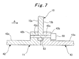
Fig. 7] Fig. 7 is a view showing the structure of attachment of a base plate in a gas turbine combustor according to a fifth embodiment of the present invention. - [
Fig. 8] Fig. 8 is a view showing the structure of attachment of a base plate in a gas turbine combustor according to a sixth embodiment of the present invention. - [
Fig. 9] Fig. 9 is a view showing the structure of attachment of a base plate in a gas turbine combustor according to a seventh embodiment of the present invention. - Hereinbelow, a gas turbine combustor according to the present invention will be described in detail with reference to the drawings.
- First, a gas turbine combustor according to a first embodiment of the present invention will be described in detail with reference to
Figs. 1 to 3 . - As shown in
Fig. 1 , acombustor 1 for a gas turbine is one employing a premix combustion method, and includes acombustor swirler basket 11 in which fuel F and compressed air A for combustion are mixed and acombustor tail tube 12 in which the mixture of the fuel F and the compressed air A is combusted. Specifically, thecombustor 1 is formed by connecting a downstream opening end portion of thecombustor swirler basket 11 and an upstream opening end portion of thecombustor tail tube 12. Note that the terms upstream and downstream represent directions based on the flow of the fuel F and the compressed air A. - Further, a
pilot burner 13 and multiple main burners (premix burners) 14 are provided inside thecombustor swirler basket 11. Moreover, thepilot burner 13 and themain burners 14 are supported on an innerperipheral surface 11a of thecombustor swirler basket 11 by means of a disc-shaped base plate 15. - The
pilot burner 13 is disposed in the center of thecombustor swirler basket 11 and includes apilot cone 21, apilot nozzle 22, and apilot swirler 23. Thepilot nozzle 22 is inserted in thepilot cone 21 in such a way as to be coaxial with thepilot cone 21. Moreover, thepilot swirler 23 is interposed between the inner peripheral surface of thepilot cone 21 and the outer peripheral surface of thepilot nozzle 22. - Meanwhile, there are eight
main burners 14 provided radially outside thepilot burner 13 at an equal angular interval along the circumferential direction of the innerperipheral surface 11a of thecombustor swirler basket 11. Eachmain burner 14 includes aswirler tube 31, anextension pipe 32, a main nozzle (premix nozzle) 33, and amain swirler 34. Themain nozzle 33 is inserted in theswirler tube 31 and theextension pipe 32 in such a way as to be coaxial with theswirler tube 31 and theextension pipe 32. Moreover, themain swirler 34 is interposed between the inner peripheral surface of theswirler tube 31 and the outer peripheral surface of themain nozzle 33. - Thus, during operation of the
combustor 1, the compressed air A at high temperature and high pressure flows into the upstream opening end portion of thecombustor swirler basket 11, and is then supplied into and around thepilot burner 13 and also into and around themain burners 14. At the same time, the fuel F is also supplied into thepilot nozzle 22 of thepilot burner 13 and themain nozzles 33 of themain burners 14. - As a result, in the
pilot burner 13, first, the supplied compressed air A is swirled by thepilot swirler 23 to be mixed to the fuel F injected from thepilot nozzle 22. Thereafter, the fuel-air mixture obtained by the mixing is ignited, so that diffusion combustion is performed inside thepilot cone 21 and the downstream side (inside the combustor tail tube 12) . Then, the combusted gas produced by the diffusion combustion is supplied downstream inside thecombustor tail tube 12. - Moreover, in each
main burner 14, first, the supplied compressed air A is swirled by themain swirler 34 to be mixed to the fuel F injected from themain nozzle 33. Thereafter, the premixed fuel-air mixture obtained by the mixing is caused to swirl and flow toward the inside of thecombustor tail tube 12 from theextension pipe 32. As a result, flame of the premixed fuel-air mixture is stabilized by the diffusion flame produced by thepilot burner 13, so that the premix combustion is performed stably. Then, the combusted gas produced by this premix combustion is supplied downstream inside thecombustor tail tube 12. - Meanwhile, as shown in
Fig. 2 , asupport hole 51 for thepilot burner 13 and support holes 52 for themain burners 14 are formed in thebase plate 15. Specifically, thesupport hole 51 is bored in the center of thebase plate 15, and thepilot cone 21 of thepilot burner 13 penetrates through and is supported on thesupport hole 51. Moreover, the support holes 52 are bored around thesupport hole 51, and theextension pipes 32 of themain burners 14 penetrate through and are supported on the support holes 52. - Further, as shown in
Fig. 2 and Part (a) ofFig. 3 , multiple bolt holes 53 are formed in an outer peripheral portion of the base plate 15 (radially outside the support holes 52). These bolt holes 53 are through-holes penetrating thebase plate 15 between itsupstream surface 15a anddownstream surface 15b in the thickness direction, and are disposed at an equal angular interval along the circumferential direction of thebase plate 15. Note that, of the multiple bolt holes 53, twobolt holes 53 are representatively illustrated inFig. 2 . - On the other hand, as shown in Parts (a) and (b) of
Fig. 3 , multiple bolt receiving members (engaging portion) 41A are provided on the innerperipheral surface 11a of thecombustor swirler basket 11 at the same interval as the interval of the bolt holes 53 along the circumferential direction of the innerperipheral surface 11a. Thesebolt receiving members 41A protrude radially inward from the innerperipheral surface 11a, and abolt hole 41b is bored in anend surface 41a of eachbolt receiving member 41A. - Moreover, the
upstream surface 15a of thebase plate 15 is engaged with the end surfaces 41a of thebolt receiving members 41A such that the bolt holes 41b and the bolt holes 53 communicate with each other. Thebase plate 15 and thebolt receiving members 41A in this engaged state are fixed to each other in the thickness direction of thebase plate 15 withbolts 60. - Specifically, the
base plate 15 can be fixed to thebolt receiving members 41A by engaging theupstream surface 15a of thebase plate 15 with the end surfaces 41a of thebolt receiving members 41A and inserting thebolts 60 into the bolt holes 41b and 53 from thedownstream surface 15b side. - Thus, the
base plate 15 can be easily attached and detached by providing thebolt receiving members 41A on the innerperipheral surface 11a of thecombustor swirler basket 11 and fixing thebolt receiving members 41A and thebase plate 15 with thebolts 60. Accordingly, the maintainability of thepilot burner 13, themain burners 14, and thebase plate 15 can be improved. - Moreover, since the
upstream surface 15a of thebase plate 15 is engaged with the end surfaces 41a of thebolt receiving members 41A, and thebolts 60 are made attachable and detachable from thedownstream surface 15b side of thebase plate 15, the attachment and detachment of thebolts 60 can be easily done via the downstream opening end portion of thecombustor swirler basket 11. - Next, a gas turbine combustor according to a second embodiment of the present invention will be described in detail with reference to
Fig. 4 . - As shown in
Fig. 4 , eachbolt receiving member 41B protrudes radially inward from an innerperipheral surface 11a, and its upstream end portion has a cross section curving in such a streamlined shape as to gradually narrow as extending in a longitudinal direction (upstream in the flow direction). - Thus, by making each
bolt receiving member 41B in the streamlined shape, compressed air A supplied in acombustor swirler basket 11 can flow without being disturbed. Accordingly, the generation of the wake (low flow speed region) of the compressed air A by thebolt receiving member 41B can be reduced. - Next, a gas turbine combustor according to a third embodiment of the present invention will be described in detail with reference to
Fig. 5 . - As shown in
Fig. 5 , adownstream surface 15b of abase plate 15 is engaged withend surfaces 41a ofbolt receiving members 41A such that bolt holes 41b and bolt holes 53 communicate with each other. Moreover, thebase plate 15 and thebolt receiving members 41A in this engaged state are fixed to each other in the thickness direction of thebase plate 15 withbolts 60. - Specifically, the
base plate 15 can be fixed to thebolt receiving members 41A by engaging thedownstream surface 15b of thebase plate 15 with the end surfaces 41a of thebolt receiving members 41A and inserting thebolts 60 into the bolt holes 41b and 53 from theupstream surface 15a side. - Thus, the
base plate 15 can be easily attached and detached. Accordingly, the maintainability of apilot burner 13,main burners 14, and thebase plate 15 can be improved. - Moreover, the
downstream surface 15b of thebase plate 15 is engaged with the end surfaces 41a of thebolt receiving members 41A, and thebolts 60 are made attachable and detachable from theupstream surface 15a side of thebase plate 15. In this way, even ifbolts 60 come off from theirbolt holes bolts 60 that have come off from entering the combustion region and to prevent thebase plate 15 from tilting toward the combustion region. - Next, a gas turbine combustor according to a fourth embodiment of the present invention will be described in detail with reference to
Fig. 6 . - As shown in
Fig. 6 , eachbolt receiving member 41B protrudes radially inward from an innerperipheral surface 11a, and its downstream end portion has a cross section curving in such a streamlined shape as to gradually narrow as extending in a longitudinal direction (downstream in the flow direction). - Thus, by making each
bolt receiving member 41B in the streamlined shape, compressed air A supplied in acombustor swirler basket 11 can flow without being disturbed. Accordingly, the generation of the wake (low flow speed region) of the compressed air A by thebolt receiving member 41B can be reduced. - Next, a gas turbine combustor according to a fifth embodiment of the present invention will be described in detail with reference to
Fig. 7 . - As shown in
Fig. 7 , acombustor swirler basket 11 includes an upstreaminner tube 42 and a downstreaminner tube 43. Specifically, thecombustor swirler basket 11 is formed by connecting a downstream opening end portion of the upstreaminner tube 42 and an upstream opening end portion of the downstreaminner tube 43. - An annular protruding portion (engaging portion) 42b of an annular shape is formed on an inner
peripheral surface 42a of the upstreaminner tube 42. This annular protrudingportion 42b protrudes radially inward from the innerperipheral surface 42a and is formed along the circumferential direction of the innerperipheral surface 42a. Moreover,multiple bolt holes 42c are formed in the annular protrudingportion 42b at the same interval as the interval of bolt holes 53 along the circumferential direction. - On the other hand, an annular protruding portion (engaging portion) 43b of an annular shape is formed on an inner
peripheral surface 43a of the downstreaminner tube 43. This annular protrudingportion 43b protrudes radially inward from the innerperipheral surface 43a and is formed along the circumferential direction of the innerperipheral surface 43a. Moreover,multiple bolt holes 43c are formed in the annular protrudingportion 43b at the same interval as the interval of the bolt holes 53 along the circumferential direction. - Specifically, the
combustor swirler basket 11 is such that the annular protrudingportions combustor swirler basket 11 and the bolt holes 42c and 43c are disposed coaxially with each other by bringing the downstream opening end portion of the upstreaminner tube 42 and the upstream opening end portion of the downstreaminner tube 43 into contact with each other. Here, a gap equivalent to the thickness of abase plate 15 is formed between the annular protrudingportions - Moreover, the
base plate 15 is engaged between the annular protrudingportions base plate 15 and the annular protrudingportions base plate 15 withbolts 60. - In other words, the
base plate 15 is held between the annular protrudingportions inner tube 42 and the downstreaminner tube 43 are brought into contact with each other, and thebolts 60 are inserted into thebolt holes downstream surface 15b side. In this way, thebase plate 15 can be fixed to the annular protrudingportions inner tube 42 and the downstreaminner tube 43 are connected. - Thus, to form the
combustor swirler basket 11 by bringing the upstreaminner tube 42 and the downstreaminner tube 43 into contact with each other, thebase plate 15 is engaged between the annular protrudingportions peripheral surfaces base plate 15 and the annular protrudingportions bolts 60. In this way, thebase plate 15 can be easily attached and detached. Accordingly, the maintainability of apilot burner 13,main burners 14, and thebase plate 15 can be improved. - Moreover, since the
base plate 15 is engaged between the annular protrudingportions bolts 60 are made attachable and detachable from thedownstream surface 15b side of thebase plate 15, the attachment and detachment of thebolts 60 can be easily done via a downstream opening end portion of thecombustor swirler basket 11. - Next, a gas turbine combustor according to a sixth embodiment of the present invention will be described in detail with reference to
Fig. 8 . - As shown in
Fig. 8 , abase plate 15 is engaged between annular protrudingportions base plate 15 and the annular protrudingportions base plate 15 withbolts 60. - In other words, the
base plate 15 is held between annular protrudingportions inner tube 42 and the downstreaminner tube 43 are brought into contact with each other, and thebolts 60 are inserted into thebolt holes upstream surface 15a side. In this way, thebase plate 15 can be fixed to the annular protrudingportions inner tube 42 and the downstreaminner tube 43 are connected. - Thus, the
base plate 15 can be easily attached and detached. Accordingly, the maintainability of apilot burner 13,main burners 14, and thebase plate 15 can be improved. - Next, a gas turbine combustor according to a seventh embodiment of the present invention will be described in detail with reference to
Fig. 9 . - As shown in
Figs. 2 and9 , multiple bolt holes 54 are formed in an outer peripheral portion of a base plate 15 (radially outside support holes 52) . These bolt holes 54 are blind holes radially penetrating thebase plate 15 from its outerperipheral end surface 15c, and are disposed at an equal angular interval along the circumferential direction of thebase plate 15. Note that, of the multiple bolt holes 54, twobolt holes 54 are representatively illustrated inFig. 2 . - On the other hand, as shown in
Fig. 9 , an annular step portion (engaging portion) 44 of an annular shape is formed on an innerperipheral surface 11a of acombustor swirler basket 11. Thisannular step portion 44 protrudes radially inward from the innerperipheral surface 11a, and is formed along the circumferential direction of the innerperipheral surface 11a. - Further, multiple bolt holes 45 are formed in the inner
peripheral surface 11a immediately below theannular step portion 44. These bolt holes 45 are through-holes radially penetrating through thecombustor swirler basket 11 and are formed at the same interval as the interval of the bolt holes 54. - Moreover, the
base plate 15 is engaged with theannular step portion 44 such that the bolt holes 45 and the bolt holes 54 communicate with each other. Thecombustor swirler basket 11 and thebase plate 15 in this engaged state are fixed to each other in the radial direction withbolts 60. - Specifically, the
base plate 15 can be fixed to the innerperipheral surface 11a of thecombustor swirler basket 11 by engaging thebase plate 15 with theannular step portion 44 and inserting thebolts 60 into the bolt holes 45 and 54 from radially outside thecombustor swirler basket 11. - Thus, the
base plate 15 can be easily attached and detached by forming theannular step portion 44 on the innerperipheral surface 11a of thecombustor swirler basket 11, engaging theannular step portion 44 and thebase plate 15 with each other, and fixing the innerperipheral surface 11a of thecombustor swirler basket 11 and the outerperipheral end surface 15c of thebase plate 15 to each other. Accordingly, the maintainability of apilot burner 13,main burners 14, and thebase plate 15 can be improved. - Moreover, since the inner
peripheral surface 11a of thecombustor swirler basket 11 and the outerperipheral end surface 15c of thebase plate 15 are fixed with thebolts 60, thebolts 60 are not disposed inside thecombustor swirler basket 11. Accordingly, compressed air A supplied in thecombustor swirler basket 11 can flow without being disturbed. - The present invention is applicable to gas turbine combustors in which a pilot burner and main burners can be attached accurately.
Claims (4)
- A gas turbine combustor, characterized in that
the gas turbine combustor comprises:a pilot burner disposed in a center of a combustor swirler basket;a plurality of main burners disposed radially outside the pilot burner along a circumferential direction of an inner peripheral surface of the combustor swirler basket;a base plate disposed inside the combustor swirler basket and supporting the pilot burner and the main burners; andan engaging portion protruding radially inward from the inner peripheral surface and engaged with the base plate, andthe base plate and any one of the engaging portion and the inner peripheral surface are fixed to each other with a bolt. - The gas turbine combustor according to claim 1, characterized in that
the engaging portion is a bolt receiving portion having a streamlined shape along a direction of flow of compressed air to be supplied in the combustor swirler basket, and
the base plate and the bolt receiving portion are fixed to each other with the bolt. - The gas turbine combustor according to claim 1, characterized in that
the engaging portion is two annular protruding portions formed along the circumferential direction of the inner peripheral surface and disposed side by side in an axial direction of the combustor swirler basket, and
the base plate and the annular protruding portions are fixed to each other with the bolt with the base plate engaged between the annular protruding portions. - The gas turbine combustor according to claim 1, characterized in that
the engaging portion is an annular step portion formed along the circumferential direction of the inner peripheral surface, and
the base plate and the inner peripheral surface are fixed to each other with the bolt with the base plate and the annular step portion engaged with each other.
Applications Claiming Priority (2)
| Application Number | Priority Date | Filing Date | Title |
|---|---|---|---|
| JP2011250242 | 2011-11-16 | ||
| PCT/JP2012/079457 WO2013073549A1 (en) | 2011-11-16 | 2012-11-14 | Gas turbine combustor |
Publications (3)
| Publication Number | Publication Date |
|---|---|
| EP2781838A1 true EP2781838A1 (en) | 2014-09-24 |
| EP2781838A4 EP2781838A4 (en) | 2015-11-25 |
| EP2781838B1 EP2781838B1 (en) | 2019-04-24 |
Family
ID=48429605
Family Applications (1)
| Application Number | Title | Priority Date | Filing Date |
|---|---|---|---|
| EP12850002.2A Active EP2781838B1 (en) | 2011-11-16 | 2012-11-14 | Gas turbine combustor |
Country Status (6)
| Country | Link |
|---|---|
| US (1) | US20140311151A1 (en) |
| EP (1) | EP2781838B1 (en) |
| JP (1) | JP5762558B2 (en) |
| KR (1) | KR101614636B1 (en) |
| CN (1) | CN103917827B (en) |
| WO (1) | WO2013073549A1 (en) |
Families Citing this family (9)
| Publication number | Priority date | Publication date | Assignee | Title |
|---|---|---|---|---|
| US8375548B2 (en) * | 2009-10-07 | 2013-02-19 | Pratt & Whitney Canada Corp. | Fuel nozzle and method of repair |
| US10125634B2 (en) * | 2015-12-10 | 2018-11-13 | General Electric Company | Combustor assembly alignment and securement systems |
| US10669942B2 (en) * | 2017-02-23 | 2020-06-02 | General Electric Company | Endcover assembly for a combustor |
| US10584877B2 (en) * | 2017-04-28 | 2020-03-10 | DOOSAN Heavy Industries Construction Co., LTD | Device to correct flow non-uniformity within a combustion system |
| CN109185923B (en) * | 2018-08-03 | 2023-09-12 | 新奥能源动力科技(上海)有限公司 | Combustion chamber head device, combustion chamber and gas turbine |
| CN109185924B (en) * | 2018-08-03 | 2023-09-12 | 新奥能源动力科技(上海)有限公司 | Combustion chamber head device, combustion chamber and gas turbine |
| GB201909168D0 (en) * | 2019-06-26 | 2019-08-07 | Rolls Royce Plc | Fuel injector |
| CN114754378B (en) * | 2022-06-13 | 2022-08-19 | 成都中科翼能科技有限公司 | Gas turbine combustor structure |
| US20260078905A1 (en) * | 2024-09-17 | 2026-03-19 | General Electric Company | Turbine engine with combustion section and fuel passage that supplies hydrogen-containing fuel to combustion section |
Family Cites Families (26)
| Publication number | Priority date | Publication date | Assignee | Title |
|---|---|---|---|---|
| US3905192A (en) * | 1974-08-29 | 1975-09-16 | United Aircraft Corp | Combustor having staged premixing tubes |
| GB2060854B (en) * | 1979-10-09 | 1984-01-25 | Proizv Obiedine Nev Zarod Im V | Annular combuster for a gas turbine engine |
| DE2950535A1 (en) * | 1979-11-23 | 1981-06-11 | BBC AG Brown, Boveri & Cie., Baden, Aargau | COMBUSTION CHAMBER OF A GAS TURBINE WITH PRE-MIXING / PRE-EVAPORATING ELEMENTS |
| US5323605A (en) * | 1990-10-01 | 1994-06-28 | General Electric Company | Double dome arched combustor |
| FR2686683B1 (en) * | 1992-01-28 | 1994-04-01 | Snecma | TURBOMACHINE WITH REMOVABLE COMBUSTION CHAMBER. |
| US5303554A (en) * | 1992-11-27 | 1994-04-19 | Solar Turbines Incorporated | Low NOx injector with central air swirling and angled fuel inlets |
| US5400491A (en) * | 1993-07-14 | 1995-03-28 | United Technologies Corporation | Apparatus for repairing a combustion chamber assembly |
| GB2293232B (en) * | 1994-09-15 | 1998-05-20 | Rolls Royce Plc | A combustion chamber assembly |
| US5916142A (en) * | 1996-10-21 | 1999-06-29 | General Electric Company | Self-aligning swirler with ball joint |
| JP3592912B2 (en) * | 1997-11-13 | 2004-11-24 | 三菱重工業株式会社 | Gas turbine combustor |
| DE69919764T2 (en) * | 1998-02-09 | 2005-09-01 | Mitsubishi Heavy Industries, Ltd. | combustion chamber |
| GB9813972D0 (en) * | 1998-06-30 | 1998-08-26 | Rolls Royce Plc | A combustion chamber |
| CA2288555C (en) * | 1998-11-12 | 2007-01-23 | Mitsubishi Heavy Industries, Ltd. | Gas turbine combustor |
| JP3364169B2 (en) * | 1999-06-09 | 2003-01-08 | 三菱重工業株式会社 | Gas turbine and its combustor |
| US6467988B1 (en) | 2000-05-20 | 2002-10-22 | General Electric Company | Reducing cracking adjacent shell flange connecting bolts |
| FR2825783B1 (en) * | 2001-06-06 | 2003-11-07 | Snecma Moteurs | HANGING OF CMC COMBUSTION CHAMBER OF TURBOMACHINE BY BRAZED LEGS |
| US6672073B2 (en) * | 2002-05-22 | 2004-01-06 | Siemens Westinghouse Power Corporation | System and method for supporting fuel nozzles in a gas turbine combustor utilizing a support plate |
| JP3840556B2 (en) * | 2002-08-22 | 2006-11-01 | 川崎重工業株式会社 | Combustor liner seal structure |
| US6705087B1 (en) * | 2002-09-13 | 2004-03-16 | Siemens Westinghouse Power Corporation | Swirler assembly with improved vibrational response |
| US7080515B2 (en) * | 2002-12-23 | 2006-07-25 | Siemens Westinghouse Power Corporation | Gas turbine can annular combustor |
| JP4070758B2 (en) * | 2004-09-10 | 2008-04-02 | 三菱重工業株式会社 | Gas turbine combustor |
| FR2897144B1 (en) * | 2006-02-08 | 2008-05-02 | Snecma Sa | COMBUSTION CHAMBER FOR TURBOMACHINE WITH TANGENTIAL SLOTS |
| US7540152B2 (en) * | 2006-02-27 | 2009-06-02 | Mitsubishi Heavy Industries, Ltd. | Combustor |
| WO2009022449A1 (en) * | 2007-08-10 | 2009-02-19 | Kawasaki Jukogyo Kabushiki Kaisha | Combustor |
| DE102009032277A1 (en) * | 2009-07-08 | 2011-01-20 | Rolls-Royce Deutschland Ltd & Co Kg | Combustion chamber head of a gas turbine |
| JP2011208929A (en) * | 2010-03-31 | 2011-10-20 | Hitachi Ltd | Backfire detecting method of gas turbine combustor |
-
2012
- 2012-11-14 US US14/358,413 patent/US20140311151A1/en not_active Abandoned
- 2012-11-14 EP EP12850002.2A patent/EP2781838B1/en active Active
- 2012-11-14 CN CN201280054924.9A patent/CN103917827B/en active Active
- 2012-11-14 JP JP2013544282A patent/JP5762558B2/en active Active
- 2012-11-14 KR KR1020147012832A patent/KR101614636B1/en active Active
- 2012-11-14 WO PCT/JP2012/079457 patent/WO2013073549A1/en not_active Ceased
Also Published As
| Publication number | Publication date |
|---|---|
| KR20140077961A (en) | 2014-06-24 |
| JPWO2013073549A1 (en) | 2015-04-02 |
| WO2013073549A1 (en) | 2013-05-23 |
| CN103917827B (en) | 2016-07-13 |
| CN103917827A (en) | 2014-07-09 |
| EP2781838B1 (en) | 2019-04-24 |
| US20140311151A1 (en) | 2014-10-23 |
| JP5762558B2 (en) | 2015-08-12 |
| EP2781838A4 (en) | 2015-11-25 |
| KR101614636B1 (en) | 2016-04-21 |
Similar Documents
| Publication | Publication Date | Title |
|---|---|---|
| EP2781838B1 (en) | Gas turbine combustor | |
| EP2554910B1 (en) | Methods relating to integrating late lean injection into combustion turbine engines | |
| US8919673B2 (en) | Apparatus and method for a fuel nozzle | |
| US8484978B2 (en) | Fuel nozzle assembly that exhibits a frequency different from a natural operating frequency of a gas turbine engine and method of assembling the same | |
| US8113000B2 (en) | Flashback resistant pre-mixer assembly | |
| JP5374031B2 (en) | Apparatus and gas turbine engine for making it possible to reduce NOx emissions in a turbine engine | |
| US9010120B2 (en) | Assemblies and apparatus related to integrating late lean injection into combustion turbine engines | |
| EP2980483B1 (en) | Gas turbine combustor | |
| US8919137B2 (en) | Assemblies and apparatus related to integrating late lean injection into combustion turbine engines | |
| US9200571B2 (en) | Fuel nozzle assembly for a gas turbine engine | |
| US20100071376A1 (en) | Combustor Assembly in a Gas Turbine Engine | |
| EP3396252A1 (en) | Fuel injection device | |
| EP2949904B1 (en) | Combustor and gas turbine | |
| EP2213943A2 (en) | Combustor assembly for use in a gas turbine engine and method of assembling same | |
| JP2015096794A (en) | Gas turbine combustor | |
| EP2438357A2 (en) | Burner, operating method and assembly method | |
| JP6840468B2 (en) | Gas turbine combustor | |
| EP3184901B1 (en) | Fuel injecting device | |
| JP2013068348A (en) | Gas turbine combustor | |
| WO2025037503A1 (en) | Fuel supply pipe assembly, gas turbine combustor, and gas turbine | |
| JP2005195288A (en) | Gas turbine combustor | |
| JP2004019973A (en) | Gas turbine combustor |
Legal Events
| Date | Code | Title | Description |
|---|---|---|---|
| PUAI | Public reference made under article 153(3) epc to a published international application that has entered the european phase |
Free format text: ORIGINAL CODE: 0009012 |
|
| 17P | Request for examination filed |
Effective date: 20140516 |
|
| AK | Designated contracting states |
Kind code of ref document: A1 Designated state(s): AL AT BE BG CH CY CZ DE DK EE ES FI FR GB GR HR HU IE IS IT LI LT LU LV MC MK MT NL NO PL PT RO RS SE SI SK SM TR |
|
| DAX | Request for extension of the european patent (deleted) | ||
| RAP1 | Party data changed (applicant data changed or rights of an application transferred) |
Owner name: MITSUBISHI HITACHI POWER SYSTEMS, LTD. |
|
| RA4 | Supplementary search report drawn up and despatched (corrected) |
Effective date: 20151022 |
|
| RIC1 | Information provided on ipc code assigned before grant |
Ipc: F23R 3/42 20060101ALI20151016BHEP Ipc: F23R 3/28 20060101ALI20151016BHEP Ipc: F23R 3/60 20060101AFI20151016BHEP Ipc: F02C 7/00 20060101ALI20151016BHEP Ipc: F02C 7/20 20060101ALI20151016BHEP |
|
| STAA | Information on the status of an ep patent application or granted ep patent |
Free format text: STATUS: EXAMINATION IS IN PROGRESS |
|
| 17Q | First examination report despatched |
Effective date: 20180528 |
|
| GRAP | Despatch of communication of intention to grant a patent |
Free format text: ORIGINAL CODE: EPIDOSNIGR1 |
|
| STAA | Information on the status of an ep patent application or granted ep patent |
Free format text: STATUS: GRANT OF PATENT IS INTENDED |
|
| INTG | Intention to grant announced |
Effective date: 20181120 |
|
| GRAS | Grant fee paid |
Free format text: ORIGINAL CODE: EPIDOSNIGR3 |
|
| GRAA | (expected) grant |
Free format text: ORIGINAL CODE: 0009210 |
|
| STAA | Information on the status of an ep patent application or granted ep patent |
Free format text: STATUS: THE PATENT HAS BEEN GRANTED |
|
| AK | Designated contracting states |
Kind code of ref document: B1 Designated state(s): AL AT BE BG CH CY CZ DE DK EE ES FI FR GB GR HR HU IE IS IT LI LT LU LV MC MK MT NL NO PL PT RO RS SE SI SK SM TR |
|
| REG | Reference to a national code |
Ref country code: GB Ref legal event code: FG4D |
|
| REG | Reference to a national code |
Ref country code: CH Ref legal event code: EP |
|
| REG | Reference to a national code |
Ref country code: AT Ref legal event code: REF Ref document number: 1124596 Country of ref document: AT Kind code of ref document: T Effective date: 20190515 Ref country code: IE Ref legal event code: FG4D |
|
| REG | Reference to a national code |
Ref country code: DE Ref legal event code: R096 Ref document number: 602012059440 Country of ref document: DE |
|
| REG | Reference to a national code |
Ref country code: NL Ref legal event code: MP Effective date: 20190424 |
|
| REG | Reference to a national code |
Ref country code: LT Ref legal event code: MG4D |
|
| PG25 | Lapsed in a contracting state [announced via postgrant information from national office to epo] |
Ref country code: NL Free format text: LAPSE BECAUSE OF FAILURE TO SUBMIT A TRANSLATION OF THE DESCRIPTION OR TO PAY THE FEE WITHIN THE PRESCRIBED TIME-LIMIT Effective date: 20190424 |
|
| PG25 | Lapsed in a contracting state [announced via postgrant information from national office to epo] |
Ref country code: HR Free format text: LAPSE BECAUSE OF FAILURE TO SUBMIT A TRANSLATION OF THE DESCRIPTION OR TO PAY THE FEE WITHIN THE PRESCRIBED TIME-LIMIT Effective date: 20190424 Ref country code: SE Free format text: LAPSE BECAUSE OF FAILURE TO SUBMIT A TRANSLATION OF THE DESCRIPTION OR TO PAY THE FEE WITHIN THE PRESCRIBED TIME-LIMIT Effective date: 20190424 Ref country code: ES Free format text: LAPSE BECAUSE OF FAILURE TO SUBMIT A TRANSLATION OF THE DESCRIPTION OR TO PAY THE FEE WITHIN THE PRESCRIBED TIME-LIMIT Effective date: 20190424 Ref country code: LT Free format text: LAPSE BECAUSE OF FAILURE TO SUBMIT A TRANSLATION OF THE DESCRIPTION OR TO PAY THE FEE WITHIN THE PRESCRIBED TIME-LIMIT Effective date: 20190424 Ref country code: FI Free format text: LAPSE BECAUSE OF FAILURE TO SUBMIT A TRANSLATION OF THE DESCRIPTION OR TO PAY THE FEE WITHIN THE PRESCRIBED TIME-LIMIT Effective date: 20190424 Ref country code: NO Free format text: LAPSE BECAUSE OF FAILURE TO SUBMIT A TRANSLATION OF THE DESCRIPTION OR TO PAY THE FEE WITHIN THE PRESCRIBED TIME-LIMIT Effective date: 20190724 Ref country code: PT Free format text: LAPSE BECAUSE OF FAILURE TO SUBMIT A TRANSLATION OF THE DESCRIPTION OR TO PAY THE FEE WITHIN THE PRESCRIBED TIME-LIMIT Effective date: 20190824 Ref country code: AL Free format text: LAPSE BECAUSE OF FAILURE TO SUBMIT A TRANSLATION OF THE DESCRIPTION OR TO PAY THE FEE WITHIN THE PRESCRIBED TIME-LIMIT Effective date: 20190424 |
|
| PG25 | Lapsed in a contracting state [announced via postgrant information from national office to epo] |
Ref country code: BG Free format text: LAPSE BECAUSE OF FAILURE TO SUBMIT A TRANSLATION OF THE DESCRIPTION OR TO PAY THE FEE WITHIN THE PRESCRIBED TIME-LIMIT Effective date: 20190724 Ref country code: PL Free format text: LAPSE BECAUSE OF FAILURE TO SUBMIT A TRANSLATION OF THE DESCRIPTION OR TO PAY THE FEE WITHIN THE PRESCRIBED TIME-LIMIT Effective date: 20190424 Ref country code: GR Free format text: LAPSE BECAUSE OF FAILURE TO SUBMIT A TRANSLATION OF THE DESCRIPTION OR TO PAY THE FEE WITHIN THE PRESCRIBED TIME-LIMIT Effective date: 20190725 Ref country code: LV Free format text: LAPSE BECAUSE OF FAILURE TO SUBMIT A TRANSLATION OF THE DESCRIPTION OR TO PAY THE FEE WITHIN THE PRESCRIBED TIME-LIMIT Effective date: 20190424 Ref country code: RS Free format text: LAPSE BECAUSE OF FAILURE TO SUBMIT A TRANSLATION OF THE DESCRIPTION OR TO PAY THE FEE WITHIN THE PRESCRIBED TIME-LIMIT Effective date: 20190424 |
|
| REG | Reference to a national code |
Ref country code: AT Ref legal event code: MK05 Ref document number: 1124596 Country of ref document: AT Kind code of ref document: T Effective date: 20190424 |
|
| PG25 | Lapsed in a contracting state [announced via postgrant information from national office to epo] |
Ref country code: IS Free format text: LAPSE BECAUSE OF FAILURE TO SUBMIT A TRANSLATION OF THE DESCRIPTION OR TO PAY THE FEE WITHIN THE PRESCRIBED TIME-LIMIT Effective date: 20190824 |
|
| REG | Reference to a national code |
Ref country code: DE Ref legal event code: R097 Ref document number: 602012059440 Country of ref document: DE |
|
| PG25 | Lapsed in a contracting state [announced via postgrant information from national office to epo] |
Ref country code: SK Free format text: LAPSE BECAUSE OF FAILURE TO SUBMIT A TRANSLATION OF THE DESCRIPTION OR TO PAY THE FEE WITHIN THE PRESCRIBED TIME-LIMIT Effective date: 20190424 Ref country code: CZ Free format text: LAPSE BECAUSE OF FAILURE TO SUBMIT A TRANSLATION OF THE DESCRIPTION OR TO PAY THE FEE WITHIN THE PRESCRIBED TIME-LIMIT Effective date: 20190424 Ref country code: RO Free format text: LAPSE BECAUSE OF FAILURE TO SUBMIT A TRANSLATION OF THE DESCRIPTION OR TO PAY THE FEE WITHIN THE PRESCRIBED TIME-LIMIT Effective date: 20190424 Ref country code: DK Free format text: LAPSE BECAUSE OF FAILURE TO SUBMIT A TRANSLATION OF THE DESCRIPTION OR TO PAY THE FEE WITHIN THE PRESCRIBED TIME-LIMIT Effective date: 20190424 Ref country code: EE Free format text: LAPSE BECAUSE OF FAILURE TO SUBMIT A TRANSLATION OF THE DESCRIPTION OR TO PAY THE FEE WITHIN THE PRESCRIBED TIME-LIMIT Effective date: 20190424 Ref country code: AT Free format text: LAPSE BECAUSE OF FAILURE TO SUBMIT A TRANSLATION OF THE DESCRIPTION OR TO PAY THE FEE WITHIN THE PRESCRIBED TIME-LIMIT Effective date: 20190424 |
|
| PG25 | Lapsed in a contracting state [announced via postgrant information from national office to epo] |
Ref country code: SM Free format text: LAPSE BECAUSE OF FAILURE TO SUBMIT A TRANSLATION OF THE DESCRIPTION OR TO PAY THE FEE WITHIN THE PRESCRIBED TIME-LIMIT Effective date: 20190424 Ref country code: IT Free format text: LAPSE BECAUSE OF FAILURE TO SUBMIT A TRANSLATION OF THE DESCRIPTION OR TO PAY THE FEE WITHIN THE PRESCRIBED TIME-LIMIT Effective date: 20190424 |
|
| PLBE | No opposition filed within time limit |
Free format text: ORIGINAL CODE: 0009261 |
|
| STAA | Information on the status of an ep patent application or granted ep patent |
Free format text: STATUS: NO OPPOSITION FILED WITHIN TIME LIMIT |
|
| PG25 | Lapsed in a contracting state [announced via postgrant information from national office to epo] |
Ref country code: TR Free format text: LAPSE BECAUSE OF FAILURE TO SUBMIT A TRANSLATION OF THE DESCRIPTION OR TO PAY THE FEE WITHIN THE PRESCRIBED TIME-LIMIT Effective date: 20190424 |
|
| 26N | No opposition filed |
Effective date: 20200127 |
|
| PG25 | Lapsed in a contracting state [announced via postgrant information from national office to epo] |
Ref country code: SI Free format text: LAPSE BECAUSE OF FAILURE TO SUBMIT A TRANSLATION OF THE DESCRIPTION OR TO PAY THE FEE WITHIN THE PRESCRIBED TIME-LIMIT Effective date: 20190424 |
|
| REG | Reference to a national code |
Ref country code: CH Ref legal event code: PL |
|
| PG25 | Lapsed in a contracting state [announced via postgrant information from national office to epo] |
Ref country code: LI Free format text: LAPSE BECAUSE OF NON-PAYMENT OF DUE FEES Effective date: 20191130 Ref country code: CH Free format text: LAPSE BECAUSE OF NON-PAYMENT OF DUE FEES Effective date: 20191130 Ref country code: MC Free format text: LAPSE BECAUSE OF FAILURE TO SUBMIT A TRANSLATION OF THE DESCRIPTION OR TO PAY THE FEE WITHIN THE PRESCRIBED TIME-LIMIT Effective date: 20190424 Ref country code: LU Free format text: LAPSE BECAUSE OF NON-PAYMENT OF DUE FEES Effective date: 20191114 |
|
| REG | Reference to a national code |
Ref country code: BE Ref legal event code: MM Effective date: 20191130 |
|
| GBPC | Gb: european patent ceased through non-payment of renewal fee |
Effective date: 20191114 |
|
| PG25 | Lapsed in a contracting state [announced via postgrant information from national office to epo] |
Ref country code: IE Free format text: LAPSE BECAUSE OF NON-PAYMENT OF DUE FEES Effective date: 20191114 Ref country code: FR Free format text: LAPSE BECAUSE OF NON-PAYMENT OF DUE FEES Effective date: 20191130 Ref country code: GB Free format text: LAPSE BECAUSE OF NON-PAYMENT OF DUE FEES Effective date: 20191114 |
|
| PG25 | Lapsed in a contracting state [announced via postgrant information from national office to epo] |
Ref country code: BE Free format text: LAPSE BECAUSE OF NON-PAYMENT OF DUE FEES Effective date: 20191130 |
|
| REG | Reference to a national code |
Ref country code: DE Ref legal event code: R082 Ref document number: 602012059440 Country of ref document: DE Representative=s name: HENKEL & PARTNER MBB PATENTANWALTSKANZLEI, REC, DE Ref country code: DE Ref legal event code: R081 Ref document number: 602012059440 Country of ref document: DE Owner name: MITSUBISHI POWER, LTD., JP Free format text: FORMER OWNER: MITSUBISHI HITACHI POWER SYSTEMS, LTD., YOKOHAMA, JP |
|
| PG25 | Lapsed in a contracting state [announced via postgrant information from national office to epo] |
Ref country code: CY Free format text: LAPSE BECAUSE OF FAILURE TO SUBMIT A TRANSLATION OF THE DESCRIPTION OR TO PAY THE FEE WITHIN THE PRESCRIBED TIME-LIMIT Effective date: 20190424 |
|
| PG25 | Lapsed in a contracting state [announced via postgrant information from national office to epo] |
Ref country code: MT Free format text: LAPSE BECAUSE OF FAILURE TO SUBMIT A TRANSLATION OF THE DESCRIPTION OR TO PAY THE FEE WITHIN THE PRESCRIBED TIME-LIMIT Effective date: 20190424 Ref country code: HU Free format text: LAPSE BECAUSE OF FAILURE TO SUBMIT A TRANSLATION OF THE DESCRIPTION OR TO PAY THE FEE WITHIN THE PRESCRIBED TIME-LIMIT; INVALID AB INITIO Effective date: 20121114 |
|
| PG25 | Lapsed in a contracting state [announced via postgrant information from national office to epo] |
Ref country code: MK Free format text: LAPSE BECAUSE OF FAILURE TO SUBMIT A TRANSLATION OF THE DESCRIPTION OR TO PAY THE FEE WITHIN THE PRESCRIBED TIME-LIMIT Effective date: 20190424 |
|
| PGFP | Annual fee paid to national office [announced via postgrant information from national office to epo] |
Ref country code: DE Payment date: 20250930 Year of fee payment: 14 |