EP2781750A1 - Internal gear pump - Google Patents
Internal gear pump Download PDFInfo
- Publication number
- EP2781750A1 EP2781750A1 EP14160628.5A EP14160628A EP2781750A1 EP 2781750 A1 EP2781750 A1 EP 2781750A1 EP 14160628 A EP14160628 A EP 14160628A EP 2781750 A1 EP2781750 A1 EP 2781750A1
- Authority
- EP
- European Patent Office
- Prior art keywords
- discharge
- suction
- relief
- side groove
- pump
- Prior art date
- Legal status (The legal status is an assumption and is not a legal conclusion. Google has not performed a legal analysis and makes no representation as to the accuracy of the status listed.)
- Granted
Links
Images


Classifications
-
- F—MECHANICAL ENGINEERING; LIGHTING; HEATING; WEAPONS; BLASTING
- F04—POSITIVE - DISPLACEMENT MACHINES FOR LIQUIDS; PUMPS FOR LIQUIDS OR ELASTIC FLUIDS
- F04C—ROTARY-PISTON, OR OSCILLATING-PISTON, POSITIVE-DISPLACEMENT MACHINES FOR LIQUIDS; ROTARY-PISTON, OR OSCILLATING-PISTON, POSITIVE-DISPLACEMENT PUMPS
- F04C2/00—Rotary-piston machines or pumps
- F04C2/08—Rotary-piston machines or pumps of intermeshing-engagement type, i.e. with engagement of co-operating members similar to that of toothed gearing
- F04C2/10—Rotary-piston machines or pumps of intermeshing-engagement type, i.e. with engagement of co-operating members similar to that of toothed gearing of internal-axis type with the outer member having more teeth or tooth-equivalents, e.g. rollers, than the inner member
- F04C2/103—Rotary-piston machines or pumps of intermeshing-engagement type, i.e. with engagement of co-operating members similar to that of toothed gearing of internal-axis type with the outer member having more teeth or tooth-equivalents, e.g. rollers, than the inner member one member having simultaneously a rotational movement about its own axis and an orbital movement
- F04C2/105—Details concerning timing or distribution valves
-
- F—MECHANICAL ENGINEERING; LIGHTING; HEATING; WEAPONS; BLASTING
- F04—POSITIVE - DISPLACEMENT MACHINES FOR LIQUIDS; PUMPS FOR LIQUIDS OR ELASTIC FLUIDS
- F04C—ROTARY-PISTON, OR OSCILLATING-PISTON, POSITIVE-DISPLACEMENT MACHINES FOR LIQUIDS; ROTARY-PISTON, OR OSCILLATING-PISTON, POSITIVE-DISPLACEMENT PUMPS
- F04C2/00—Rotary-piston machines or pumps
- F04C2/08—Rotary-piston machines or pumps of intermeshing-engagement type, i.e. with engagement of co-operating members similar to that of toothed gearing
- F04C2/10—Rotary-piston machines or pumps of intermeshing-engagement type, i.e. with engagement of co-operating members similar to that of toothed gearing of internal-axis type with the outer member having more teeth or tooth-equivalents, e.g. rollers, than the inner member
- F04C2/102—Rotary-piston machines or pumps of intermeshing-engagement type, i.e. with engagement of co-operating members similar to that of toothed gearing of internal-axis type with the outer member having more teeth or tooth-equivalents, e.g. rollers, than the inner member the two members rotating simultaneously around their respective axes
-
- F—MECHANICAL ENGINEERING; LIGHTING; HEATING; WEAPONS; BLASTING
- F01—MACHINES OR ENGINES IN GENERAL; ENGINE PLANTS IN GENERAL; STEAM ENGINES
- F01C—ROTARY-PISTON OR OSCILLATING-PISTON MACHINES OR ENGINES
- F01C21/00—Component parts, details or accessories not provided for in groups F01C1/00 - F01C20/00
- F01C21/10—Outer members for co-operation with rotary pistons; Casings
-
- F—MECHANICAL ENGINEERING; LIGHTING; HEATING; WEAPONS; BLASTING
- F04—POSITIVE - DISPLACEMENT MACHINES FOR LIQUIDS; PUMPS FOR LIQUIDS OR ELASTIC FLUIDS
- F04C—ROTARY-PISTON, OR OSCILLATING-PISTON, POSITIVE-DISPLACEMENT MACHINES FOR LIQUIDS; ROTARY-PISTON, OR OSCILLATING-PISTON, POSITIVE-DISPLACEMENT PUMPS
- F04C14/00—Control of, monitoring of, or safety arrangements for, machines, pumps or pumping installations
- F04C14/24—Control of, monitoring of, or safety arrangements for, machines, pumps or pumping installations characterised by using valves controlling pressure or flow rate, e.g. discharge valves or unloading valves
- F04C14/26—Control of, monitoring of, or safety arrangements for, machines, pumps or pumping installations characterised by using valves controlling pressure or flow rate, e.g. discharge valves or unloading valves using bypass channels
-
- F—MECHANICAL ENGINEERING; LIGHTING; HEATING; WEAPONS; BLASTING
- F04—POSITIVE - DISPLACEMENT MACHINES FOR LIQUIDS; PUMPS FOR LIQUIDS OR ELASTIC FLUIDS
- F04C—ROTARY-PISTON, OR OSCILLATING-PISTON, POSITIVE-DISPLACEMENT MACHINES FOR LIQUIDS; ROTARY-PISTON, OR OSCILLATING-PISTON, POSITIVE-DISPLACEMENT PUMPS
- F04C15/00—Component parts, details or accessories of machines, pumps or pumping installations, not provided for in groups F04C2/00 - F04C14/00
- F04C15/0088—Lubrication
- F04C15/0092—Control systems for the circulation of the lubricant
Definitions
- the present invention relates to a pump that sucks in and discharges fluid such as oil.
- a vehicle having a start-stop function is generally provided with an electric oil pump.
- the required minimum hydraulic pressure is supplied to portions requiring hydraulic pressure by an electric oil pump, instead of a mechanical pump that is driven by an engine. Accordingly, the vehicle can be quickly restarted.
- the aforementioned electric oil pump includes an outer rotor, an inner rotor, and a housing.
- Internal teeth are formed on the inner periphery of the outer rotor.
- the internal teeth are formed using trochoid curves.
- External teeth are formed on the outer periphery of the inner rotor.
- the external teeth are formed using trochoid curves and mesh with the internal teeth.
- the inner rotor is rotated by a motor.
- a pump chamber, in which the outer rotor and the inner rotor are rotatably housed, is defined in the housing.
- a suction flow passage and a discharge flow passage, which communicate with the pump chamber, are formed in the housing.
- a suction-side groove with which the suction flow passage communicates and a discharge-side groove with which the discharge flow passage communicates are formed at an interval in the circumferential direction of the bottom of the pump chamber so as to be recessed in the bottom of the housing.
- JP 2008-151065 A proposes an electric oil pump including a relief valve that returns oil to a suction-side groove from a discharge-side groove when excessive pressure is applied to a discharge side of a pump chamber.
- This electric oil pump may be fitted to bosses protruding from an outer surface portion of a transmission.
- the relief valve is provided between inner and outer rotors and an outer surface of the transmission. Therefore, the thickness of the electric oil pump is increased by the thickness of the relief valve, and thus, the electric oil pump is not easily fitted to the transmission.
- An object of the invention is to provide a pump with a relief valve, whose thickness dimension is prevented from being increased.
- a pump that is fitted to bosses protruding from a fitting target portion, the pump including a housing in which a pump chamber that is a columnar space is defined, and a suction-side groove and a discharge-side groove are formed at a predetermined interval in a circumferential direction of a bottom of the pump chamber so as to be recessed in the bottom of the pump chamber; an outer rotor that is rotatably provided in the pump chamber and includes internal teeth formed at an inner peripheral side of the outer rotor; and an inner rotor that is provided inside the internal teeth, the inner rotor including external teeth that mesh with the internal teeth and are formed at an outer peripheral side of the inner rotor, wherein fitting portions that are fitted to the bosses are formed on an outer surface of the housing, wherein a protruding portion, which overlaps with the bosses in a thickness direction, is formed so as to protrude from a surface of the housing on which the fitting portions are formed, and wherein
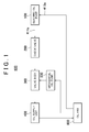
- the vehicle 900 includes an electric oil pump 100, a check valve 200, a valve body 300, an oil supply unit 400, a mechanical oil pump 500, and an oil pan 600.
- the electric oil pump 100 is a pump in which a pump body 10 (see FIG. 2 ) is driven by a motor 20.
- the electric oil pump 100 sucks in oil from the oil pan 600, and supplies the oil to the oil supply unit 400 through the check valve 200 and the valve body 300.
- the electric oil pump 100 will be described in detail below.
- the check valve 200 is provided between a discharge flow passage 19d (see FIGS. 2 and 3 ) of the electric oil pump 100 and the valve body 300.
- the check valve 200 allows oil to flow to the valve body 300 from the electric oil pump 100, but prevents oil from flowing backward to the electric oil pump 100 from the valve body 300.
- the mechanical oil pump 500 is driven by a rotational drive force of an engine (not shown).
- the mechanical oil pump 500 sucks in oil from the oil pan 600 and supplies the oil to the oil supply unit 400 through the valve body 300.
- the mechanical oil pump 500 does not supply oil when the engine stops.
- an inflow-side flow passage through which oil flows into the valve body 300, is switched to the electric oil pump 100 (check valve 200)-side flow passage or the mechanical oil pump 500-side flow passage, in accordance with a command that is sent from a vehicle ECU (not shown).
- the oil supply unit 400 is a transmission that reduces the speed of rotation, which is input from the engine (not shown), at a predetermined speed ratio and outputs the rotation, whose speed has been reduced, to a differential, a torque converter that amplifies running torque output from an output shaft of the engine and inputs the amplified running torque to the transmission, or the like.
- the oil pan 600 stores oil that is supplied to the oil supply unit 400 and is discharged from the oil supply unit 400.
- the electric oil pump 100 includes the pump body 10 and the motor 20.
- the pump body 10 is driven by the motor 20, and supplies oil, which has a predetermined hydraulic pressure, to the oil supply unit 400 during idling stop (when the engine stops).
- the pump body 10 will be described in detail below.
- the motor 20 outputs a rotational drive force to the pump body 10.
- the motor 20 includes a stator 22, a rotor 23, and a rotating shaft 24 of the rotor 23.
- the stator 22 is fixed to a housing 21 and is formed of coils.
- the rotor 23 is rotatably provided on the inner peripheral side with respect to the stator 22, and is formed of a permanent magnet.
- the structure of the pump body 10 will be described below with reference to FIGS. 2 and 3 .
- the pump body 10 includes a first housing member 11, an inner rotor 12, an outer rotor 13, a seal member 14, a relief valve 15, and a second housing member 19.
- a thickness direction z of the electric oil pump 100 or the second housing member 19 signifies the direction of the rotational axis of the inner rotor 12 or the outer rotor 13.
- a plane direction of the second housing member 19 is a direction of an XY plane that is orthogonal to the thickness direction z.
- the first housing member 11 is in the form of a block, and has a bottomed tubular shape in which a pump chamber 11b, that is, a flat columnar space is defined. As shown in FIG. 2 , an insertion hole 11a communicating with the pump chamber 11b is formed at the center of the first housing member 11.
- the rotating shaft 24 of the motor 20 is inserted into the insertion hole 11a.
- the outer rotor 13 is rotatably provided in the pump chamber 11b.
- the outer rotor 13 is in a flat columnar shape so as to have a circular cross-sectional shape, and internal teeth 13a, which form a space, are formed at the inner peripheral side of the outer rotor 13.
- the inner rotor 12 is rotatably provided inside the internal teeth 13a.
- the inner rotor 12 has a ring shape, and external teeth 12a are formed at the outer edge of the inner rotor 12.
- the internal teeth 13a and the external teeth 12a are formed using a plurality of trochoid curves.
- the number of the external teeth 12a is smaller than the number of the internal teeth 13a.
- the external teeth 12a mesh with the internal teeth 13a.
- the center of rotation of the outer rotor 13 is eccentric with respect to the center of rotation of the inner rotor 12.
- the center of the inner rotor 12 and the rotating shaft 24 of the motor 20 are fitted to each other, and thus, the inner rotor 12 and the rotating shaft 24 are rotated together.
- the second housing member 19 has a plate shape, and is fitted to the first housing member 11 so as to close an opening of the first housing member 11. As shown in FIGS. 2 , 3 , and 4 , a crescent-shaped suction-side groove 19e and a crescent-shaped discharge-side groove 19f are formed at a predetermined interval in the circumferential direction of the bottom of the pump chamber 11b so as to be recessed in the surface of the second housing member 19 facing the pump chamber 11b (i.e., in the bottom of the pump chamber 11b).
- the suction-side groove 19e and the discharge-side groove 19f face each other in the bottom of the pump chamber 11b. Positions at which the suction-side groove 19e and the discharge-side groove 19f are formed are present on a locus along which a space formed between the external teeth 12a and the internal teeth 13a is moved. As shown in FIG. 3 , the side of the pump chamber 11b on which the suction-side groove 19e is formed is a suction side. The side of the pump chamber 11b on which the discharge-side groove 19f is formed is a discharge side.
- a suction flow passage 19c which communicates with the pump chamber 11b by communicating with the bottom of the suction-side groove 19e, is formed in the second housing member 19.
- a position where the suction flow passage 19c communicates with the bottom of the suction-side groove 19e is a start end portion of the suction-side groove 19e where the space formed between the external teeth 12a and the internal teeth 13a passes through the suction-side groove 19e first.
- the discharge flow passage 19d which communicates with the pump chamber 11b by communicating with the bottom of the discharge-side groove 19f, is formed in the second housing member 19.
- a position where the discharge flow passage 19d communicates with the bottom of the discharge-side groove 19f is an intermediate portion of the discharge-side groove 19f.
- a plurality of fitting portions 19u is formed at an outer edge portion of a reverse surface 19v of the second housing member 19 (the surface of the second housing member 19 on a side opposite to the pump chamber 11b-side). Further, a fitting hole 19a is formed at each of the fitting portions 19u. As shown in FIGS. 6 and 7 , a fitting surface 19b, which is a flat surface, is formed at the outer peripheral portion around the fitting hole 19a of each of the fitting portions 19u. Furthermore, annular packing fitting recesses 19q, 19r are formed so as to be recessed in the outer peripheral portions around openings of the suction flow passage 19c and the discharge flow passage 19d in the reverse surface 19v of the second housing member 19, respectively.
- a protruding portion 19h is formed between the fitting holes 19a on the reverse surface 19v of the second housing member 19 (the surface of the second housing member 19 on which the fitting portions 19u are formed).
- the protruding portion 19h is in the form of a block and protrudes in the thickness direction z.
- the position of the protruding portion 19h in the plane direction is different from the positions at which the fitting portions 19u and the packing fitting recesses 19q, 19r are formed.
- the inner rotor 12 When the motor 20 is rotated, the inner rotor 12 is rotated and the outer rotor 13, which meshes with the external teeth 12a at the internal teeth 13a, is also rotated. Then, the space formed between the external teeth 12a and the internal teeth 13a is moved to the discharge-side groove 19f from the suction-side groove 19e, and thus, oil is supplied to the discharge flow passage 19d from the suction flow passage 19c.
- the electric oil pump 100 is operated, the pressure in the discharge side (high-pressure side) of the pump chamber 11b is higher than the pressure at the suction side (low-pressure side) of the pump chamber 11b.
- the relief valve 15 includes a suction-side relief recess 19m, a discharge-side relief recess 19n, a relief flow passage 19i, a spool 16, a spring receiving member 17, and a spring 18.
- the suction-side relief recess 19m which is recessed in the thickness direction z, is formed at the bottom of the suction-side groove 19e.
- the discharge-side relief recess 19n which is recessed in the thickness direction z, is formed at the bottom of the discharge-side groove 19f.
- the positions of the suction-side relief recess 19m and the discharge-side relief recess 19n in the plane direction correspond to a position at which the protruding portion 19h is formed.
- a position at which the suction-side relief recess 19m is formed is a terminal end portion of the suction-side groove 19e where the space formed between the external teeth 12a and the internal teeth 13a passes through the suction-side groove 19e at the end.
- a position at which the discharge-side relief recess 19n is formed is a start end portion of the discharge-side groove 19f where the space formed between the external teeth 12a and the internal teeth 13a passes through the discharge-side groove 19f first.
- the relief flow passage 19i which provides communication between the suction-side relief recess 19m and the discharge-side relief recess 19n, is formed in the protruding portion 19h and in a portion of the second housing member 19 corresponding to the position at which the protruding portion 19h is formed in the plane direction.
- the relief flow passage 19i extends along the longitudinal direction of the protruding portion 19h.
- a spring receiving hole 19j which communicates with the relief flow passage 19i and is opened to an outer end of the protruding portion 19h, is formed in the protruding portion 19h and in the portion of the second housing member 19 corresponding to the position at which the protruding portion 19h is formed in the plane direction.
- the spring receiving hole 19j extends along the longitudinal direction of the protruding portion 19h.
- the inside diameter of a connected portion of the relief flow passage 19i, which is connected to the spring receiving hole 19j, is larger than the inside diameter of a portion of the relief flow passage 19i other than this connected portion, and the connected portion of the relief flow passage 19i forms a receiving portion 19p that has the same inside diameter as the inside diameter of the spring receiving hole 19j.
- a screw groove 19k is formed on the inner peripheral surface of an opened side of the spring receiving hole 19j.
- a bottom 19s of the discharge-side relief recess 19n is formed of an inclined surface that is gradually inclined toward a portion of the relief flow passage 19i connected to the suction-side relief recess 19m, in a direction toward the lower side in the thickness direction of the second housing member 19.
- a bottom 19t of the suction-side relief recess 19m is formed of an inclined surface that is gradually inclined toward a portion of the relief flow passage 19i connected to the discharge-side relief recess 19n, in a direction toward the lower side in the thickness direction of the second housing member 19.
- the spring receiving member 17 includes a head portion 17a, a spring receiving portion 17b, and a stopper portion 17c that are formed in this order from a base end of the spring receiving member 17 toward a distal end of the spring receiving member 17.
- a screw groove is formed on the outer peripheral surface of the spring receiving portion 17b.
- the spring receiving member 17 is fitted to the protruding portion 19h so that the spring receiving portion 17b is screwed to the screw groove 19k to close the opening of the spring receiving hole 19j.
- the stopper portion 17c is inserted into the spring receiving hole 19j.
- the spool 16 has a block shape corresponding to the shape of the receiving portion 19p of the relief flow passage 19i, and has a columnar shape in this embodiment.
- the spool 16 is slidably provided in the receiving portion 19p.
- the spring 18 is provided in a space between the spring receiving hole 19j and the stopper portion 17c. In other words, the stopper portion 17c is inserted in the spring 18. One end of the spring 18 is in contact with the spring receiving portion 17b, and the other end of the spring 18 is in contact with the spool 16. The spool 16 is pressed against the receiving portion 19p by the spring 18. Since the relief flow passage 19i is closed by the spool 16 in this state, the relief flow passage 19i and the suction-side groove 19e do not communicate with each other.
- the urging force of the spring 18 is set to an urging force that allows the spool 16 to slide so that the discharge-side groove 19f and the suction-side groove 19e communicate with each other through the relief flow passage 19i when hydraulic pressure in the discharge-side groove 19f is equal to or higher than the opening pressure.
- a fitting target portion to which the electric oil pump 100 is fitted is an outer surface portion of a case 410 of the transmission.
- a plurality of ribs 411 is formed on the outer surface portion of the case 410 so that the case 410 has strength. Therefore, the outer surface portion of the case 410 is formed in an uneven shape.
- each boss 412 is in the form of a block, and has a columnar shape in this embodiment.
- a distal end of each boss 412 is a fitting target surface 412a that is a flat surface.
- a screw hole 412b is formed at each fitting target surface 412a.
- Each fitting surface 19b (see FIG. 6 ) is in contact with the corresponding fitting target surface 412a and a fitting screw (not shown) inserted in each fitting hole 19a is screwed into the corresponding screw hole 412b, and thus, the second housing member 19 is fitted to the bosses 412.
- the bosses 412 are formed in order to fit the second housing member 19 to the case 410 in a manner such that the second housing member 19 is spaced from the ribs 411 while avoiding the interference between the second housing member 19 and the ribs 411. If a space between the ribs 411 is filled with metal so that a fitting target surface to which the second housing member 19 is to be fitted is formed, the thickness of the case 410 is excessively increased. Therefore, "blowholes" may be formed during the casting of the case 410. The thickness of the case 410 is made small and the ribs 411 and the bosses 412 are formed on the case 410 in this embodiment. Therefore, the formation of "blowhole" during the casting of the case 410 is prevented and the case 410 has strength.
- a suction boss 413 and a discharge boss 414 are formed so as to protrude from the outer surface portion of the case 410.
- Each of the suction boss 413 and the discharge boss 414 is in the form of a block and has a columnar shape.
- Contact surfaces 413a, 414a which are flat surfaces, are formed at the distal ends of the suction boss 413 and the discharge boss 414, respectively.
- a suction port 413b and a discharge port 414b are formed at the contact surfaces 413a, 414a, respectively.
- a packing such as an O-ring fitted to the packing fitting recess 19q is in contact with the contact surface 413a of the suction boss 413.
- a packing such as an O-ring fitted to the packing fitting recess 19r is in contact with the contact surface 414a of the discharge boss 414.
- the suction flow passage 19c and the suction port 413b communicate with each other. Further, the discharge flow passage 19d and the discharge port 414b communicate with each other.
- the suction-side groove 19e, the discharge-side groove 19f, the suction-side relief recess 19m, and the discharge-side relief recess 19n of the second housing member 19 are formed by casting. Therefore, it is possible to form the shapes of the suction-side relief recess 19m and the discharge-side relief recess 19n with a high degree of freedom and at a low cost.
- the relief flow passage 19i and the spring receiving hole 19j are formed by drilling (cutting).
- the protruding portion 19h which protrudes in the thickness direction z, is formed on the reverse surface 19v of the second housing member 19 (housing) on which the fitting portions 19u are formed. Further, the relief valve 15 is provided in the protruding portion 19h.
- the fitting portions 19u are fitted to the bosses 412 that are formed so as to protrude from the case 410 (fitting target portion), and thus, the second housing member 19 is fitted to the case 410. That is, a space is present between the second housing member 19 and the case 410. Further, the protruding portion 19h, which is formed on the reverse surface 19v of the second housing member 19, is disposed in the space so as to overlap with the bosses 412 in the thickness direction. Furthermore, since the relief valve 15 is provided in the protruding portion 19h, the increase of the thickness of the electric oil pump 100 is prevented.
- the suction-side relief recess 19m is formed at the bottom of the suction-side groove 19e.
- the discharge-side relief recess 19n is formed at the bottom of the discharge-side groove 19f.
- the relief flow passage 19i which provides communication between the suction-side relief recess 19m and the discharge-side relief recess 19n, is formed in the protruding portion 19h and in the portion of the second housing member 19 corresponding to the position at which the protruding portion 19h is formed in the plane direction.
- the protruding portion 19h which overlaps with the bosses 412 in the thickness direction z, is a member that forms the relief flow passage 19i as described above, the second housing member 19 is not made thick. Therefore, the increase of the thickness of the electric oil pump 100 is prevented.
- the bottom 19s of the discharge-side relief recess 19n is gradually inclined toward the portion of the relief flow passage 19i connected to the suction-side relief recess 19m, in the direction toward the lower side in the thickness direction of the second housing member 19.
- the bottom 19t of the suction-side relief recess 19m is gradually inclined toward the portion of the relief flow passage 19i connected to the discharge-side relief recess 19n, in the direction toward the lower side in the thickness direction of the second housing member 19.
- the discharge-side groove 19f is smoothly connected to the relief flow passage 19i by the discharge-side relief recess 19n, and thus, the flow passage from the discharge-side groove 19f to the relief flow passage 19i is not suddenly changed.
- the suction-side groove 19e is smoothly connected to the relief flow passage 19i by the suction-side relief recess 19m, and thus, the flow passage from the suction-side groove 19e to the relief flow passage 19i is not suddenly changed.
- the suction-side relief recess 19m and the discharge-side relief recess 19n are formed by casting. Accordingly, it is possible to form the shapes of the suction-side relief recess 19m and the discharge-side relief recess 19n with a high degree of freedom. Therefore, it is possible to form the suction-side relief recess 19m and the discharge-side relief recess 19n in the shapes that do not cause the sudden change in the flow direction of oil. Furthermore, since the degree of freedom in determining the positions where the suction-side relief recess 19m and the discharge-side relief recess 19n are formed is high, it is easy to set the opening pressure for the relief valve 15. Moreover, it is possible to form the suction-side relief recess 19m and the discharge-side relief recess 19n, which have the above-mentioned shapes, at a low cost.
- the electric oil pump 100 Since the electric oil pump 100 is into contact with only the bosses 412 and the electric oil pump 100 and the case 410 are spaced from each other, the transfer of heat to the electric oil pump 100 from the case 410 is minimum. Therefore, the electric oil pump 100 is not overheated by heat generated by the transmission, and thus, an electronic circuit (not shown) provided in the electric oil pump 100 is protected from the heat.
- an urging member which presses the spool 16 to the bottom of the receiving portion 19p and urges the spool 16 in a direction in which the relief flow passage 19i is closed by the spool 16, is the spring 18.
- an elastic member such as rubber may be used as the biasing urging in an embodiment.
- the pump may be a mechanical pump without the motor 20.
- the pump according to the embodiment, which supplies oil as fluid has been described above.
- the pump may be a pump that supplies fluid such as water.
- a pump includes a second housing member in which a suction-side groove and a discharge-side groove are formed at a predetermined interval in a circumferential direction of a bottom of a pump chamber so as to be recessed in the bottom of the pump chamber.
- Fitting portions that are fitted to bosses are formed on an outer surface of the second housing member.
- a protruding portion, which overlaps with the bosses in a thickness direction, is formed so as to protrude from a surface of the housing on which the fitting portions are formed.
- a relief valve is provided in the protruding portion, and the relief valve discharges fluid from the discharge-side groove when pressure in the discharge-side groove is equal to or higher than predetermined pressure.
Landscapes
- Engineering & Computer Science (AREA)
- Mechanical Engineering (AREA)
- General Engineering & Computer Science (AREA)
- Physics & Mathematics (AREA)
- Fluid Mechanics (AREA)
- Rotary Pumps (AREA)
- Details And Applications Of Rotary Liquid Pumps (AREA)
Abstract
Description
- The present invention relates to a pump that sucks in and discharges fluid such as oil.
- A vehicle having a start-stop function is generally provided with an electric oil pump. In such a vehicle, while idling is stopped, the required minimum hydraulic pressure is supplied to portions requiring hydraulic pressure by an electric oil pump, instead of a mechanical pump that is driven by an engine. Accordingly, the vehicle can be quickly restarted.
- The aforementioned electric oil pump includes an outer rotor, an inner rotor, and a housing. Internal teeth are formed on the inner periphery of the outer rotor. The internal teeth are formed using trochoid curves. External teeth are formed on the outer periphery of the inner rotor. The external teeth are formed using trochoid curves and mesh with the internal teeth. The inner rotor is rotated by a motor. A pump chamber, in which the outer rotor and the inner rotor are rotatably housed, is defined in the housing.
- A suction flow passage and a discharge flow passage, which communicate with the pump chamber, are formed in the housing. A suction-side groove with which the suction flow passage communicates and a discharge-side groove with which the discharge flow passage communicates are formed at an interval in the circumferential direction of the bottom of the pump chamber so as to be recessed in the bottom of the housing. When the inner rotor and the outer rotor of the electric oil pump, which has the above-mentioned configuration, are rotated while meshing with each other, oil sucked from the suction flow passage is discharged from the discharge flow passage.
- Japanese Patent Application Publication No.
2008-151065 JP 2008-151065 A - This electric oil pump may be fitted to bosses protruding from an outer surface portion of a transmission. The relief valve is provided between inner and outer rotors and an outer surface of the transmission. Therefore, the thickness of the electric oil pump is increased by the thickness of the relief valve, and thus, the electric oil pump is not easily fitted to the transmission.
- An object of the invention is to provide a pump with a relief valve, whose thickness dimension is prevented from being increased.
- According to an aspect of the invention, there is provided a pump that is fitted to bosses protruding from a fitting target portion, the pump including a housing in which a pump chamber that is a columnar space is defined, and a suction-side groove and a discharge-side groove are formed at a predetermined interval in a circumferential direction of a bottom of the pump chamber so as to be recessed in the bottom of the pump chamber; an outer rotor that is rotatably provided in the pump chamber and includes internal teeth formed at an inner peripheral side of the outer rotor; and an inner rotor that is provided inside the internal teeth, the inner rotor including external teeth that mesh with the internal teeth and are formed at an outer peripheral side of the inner rotor, wherein fitting portions that are fitted to the bosses are formed on an outer surface of the housing, wherein a protruding portion, which overlaps with the bosses in a thickness direction, is formed so as to protrude from a surface of the housing on which the fitting portions are formed, and wherein a relief valve is provided in the protruding portion, and the relief valve discharges fluid from the discharge-side groove when pressure in the discharge-side groove is equal to or higher than predetermined pressure.
- The foregoing and further features and advantages of the invention will become apparent from the following description of example embodiments with reference to the accompanying drawings, wherein like numerals are used to represent like elements and wherein:
-
FIG. 1 is an explanatory diagram of an oil flow passage in a vehicle on which an electric oil pump according to an embodiment of the invention is provided; -
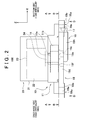
FIG. 2 is a side view of an electric oil pump; -
FIG. 3 is a sectional view of a pump portion taken along a line A-A- inFIG. 2 ; -
FIG. 4 is a surface view of a second housing member seen in a direction shown by arrows B inFIG. 2 ; -
FIG. 5 is a sectional view of a relief valve taken along a line C-C inFIG. 4 ; -
FIG. 6 is a reverse surface view of the second housing member seen in a direction shown by an arrow D inFIG. 2 ; -
FIG. 7 is a perspective view of a reverse surface side of the second housing member; and -
FIG. 8 is a perspective view illustrating a fitting target portion to which the electric oil pump is fitted. - A pump according to an embodiment of the invention will be described below with reference to the drawings. First, an oil flow passage in a
vehicle 900 in which anelectric oil pump 100 according to this embodiment is provided will be described with reference toFIG. 1 . Thevehicle 900 includes anelectric oil pump 100, acheck valve 200, avalve body 300, anoil supply unit 400, amechanical oil pump 500, and anoil pan 600. - The
electric oil pump 100 is a pump in which a pump body 10 (seeFIG. 2 ) is driven by amotor 20. Theelectric oil pump 100 sucks in oil from theoil pan 600, and supplies the oil to theoil supply unit 400 through thecheck valve 200 and thevalve body 300. Theelectric oil pump 100 will be described in detail below. - The
check valve 200 is provided between adischarge flow passage 19d (seeFIGS. 2 and3 ) of theelectric oil pump 100 and thevalve body 300. Thecheck valve 200 allows oil to flow to thevalve body 300 from theelectric oil pump 100, but prevents oil from flowing backward to theelectric oil pump 100 from thevalve body 300. - The
mechanical oil pump 500 is driven by a rotational drive force of an engine (not shown). Themechanical oil pump 500 sucks in oil from theoil pan 600 and supplies the oil to theoil supply unit 400 through thevalve body 300. Themechanical oil pump 500 does not supply oil when the engine stops. - In the
valve body 300, an inflow-side flow passage, through which oil flows into thevalve body 300, is switched to the electric oil pump 100 (check valve 200)-side flow passage or the mechanical oil pump 500-side flow passage, in accordance with a command that is sent from a vehicle ECU (not shown). - For example, the
oil supply unit 400 is a transmission that reduces the speed of rotation, which is input from the engine (not shown), at a predetermined speed ratio and outputs the rotation, whose speed has been reduced, to a differential, a torque converter that amplifies running torque output from an output shaft of the engine and inputs the amplified running torque to the transmission, or the like. - The
oil pan 600 stores oil that is supplied to theoil supply unit 400 and is discharged from theoil supply unit 400. - The
electric oil pump 100 includes thepump body 10 and themotor 20. Thepump body 10 is driven by themotor 20, and supplies oil, which has a predetermined hydraulic pressure, to theoil supply unit 400 during idling stop (when the engine stops). Thepump body 10 will be described in detail below. - The
motor 20 outputs a rotational drive force to thepump body 10. Themotor 20 includes astator 22, arotor 23, and a rotatingshaft 24 of therotor 23. Thestator 22 is fixed to ahousing 21 and is formed of coils. Therotor 23 is rotatably provided on the inner peripheral side with respect to thestator 22, and is formed of a permanent magnet. - The structure of the
pump body 10 will be described below with reference toFIGS. 2 and3 . Thepump body 10 includes afirst housing member 11, aninner rotor 12, anouter rotor 13, aseal member 14, arelief valve 15, and asecond housing member 19. In the following description, a thickness direction z of theelectric oil pump 100 or thesecond housing member 19 signifies the direction of the rotational axis of theinner rotor 12 or theouter rotor 13. Further, a plane direction of thesecond housing member 19 is a direction of an XY plane that is orthogonal to the thickness direction z. - The
first housing member 11 is in the form of a block, and has a bottomed tubular shape in which apump chamber 11b, that is, a flat columnar space is defined. As shown inFIG. 2 , aninsertion hole 11a communicating with thepump chamber 11b is formed at the center of thefirst housing member 11. The rotatingshaft 24 of themotor 20 is inserted into theinsertion hole 11a. A ring-shaped seal member 14, which is in contact with the rotatingshaft 24 over the entire circumference and seals a gap between thefirst housing member 11 and the rotatingshaft 24, is provided in theinsertion hole 11a. - As shown in
FIG. 3 , theouter rotor 13 is rotatably provided in thepump chamber 11b. Theouter rotor 13 is in a flat columnar shape so as to have a circular cross-sectional shape, andinternal teeth 13a, which form a space, are formed at the inner peripheral side of theouter rotor 13. Theinner rotor 12 is rotatably provided inside theinternal teeth 13a. - The
inner rotor 12 has a ring shape, andexternal teeth 12a are formed at the outer edge of theinner rotor 12. Theinternal teeth 13a and theexternal teeth 12a are formed using a plurality of trochoid curves. The number of theexternal teeth 12a is smaller than the number of theinternal teeth 13a. Theexternal teeth 12a mesh with theinternal teeth 13a. The center of rotation of theouter rotor 13 is eccentric with respect to the center of rotation of theinner rotor 12. The center of theinner rotor 12 and therotating shaft 24 of themotor 20 are fitted to each other, and thus, theinner rotor 12 and therotating shaft 24 are rotated together. - The
second housing member 19 has a plate shape, and is fitted to thefirst housing member 11 so as to close an opening of thefirst housing member 11. As shown inFIGS. 2 ,3 , and4 , a crescent-shaped suction-side groove 19e and a crescent-shaped discharge-side groove 19f are formed at a predetermined interval in the circumferential direction of the bottom of thepump chamber 11b so as to be recessed in the surface of thesecond housing member 19 facing thepump chamber 11b (i.e., in the bottom of thepump chamber 11b). - The suction-
side groove 19e and the discharge-side groove 19f face each other in the bottom of thepump chamber 11b. Positions at which the suction-side groove 19e and the discharge-side groove 19f are formed are present on a locus along which a space formed between theexternal teeth 12a and theinternal teeth 13a is moved. As shown inFIG. 3 , the side of thepump chamber 11b on which the suction-side groove 19e is formed is a suction side. The side of thepump chamber 11b on which the discharge-side groove 19f is formed is a discharge side. - A
suction flow passage 19c, which communicates with thepump chamber 11b by communicating with the bottom of the suction-side groove 19e, is formed in thesecond housing member 19. A position where thesuction flow passage 19c communicates with the bottom of the suction-side groove 19e is a start end portion of the suction-side groove 19e where the space formed between theexternal teeth 12a and theinternal teeth 13a passes through the suction-side groove 19e first. Thedischarge flow passage 19d, which communicates with thepump chamber 11b by communicating with the bottom of the discharge-side groove 19f, is formed in thesecond housing member 19. A position where thedischarge flow passage 19d communicates with the bottom of the discharge-side groove 19f is an intermediate portion of the discharge-side groove 19f. - As shown in
FIGS. 2 ,6 , and7 , a plurality offitting portions 19u is formed at an outer edge portion of areverse surface 19v of the second housing member 19 (the surface of thesecond housing member 19 on a side opposite to thepump chamber 11b-side). Further, afitting hole 19a is formed at each of thefitting portions 19u. As shown inFIGS. 6 and7 , afitting surface 19b, which is a flat surface, is formed at the outer peripheral portion around thefitting hole 19a of each of thefitting portions 19u. Furthermore, annularpacking fitting recesses suction flow passage 19c and thedischarge flow passage 19d in thereverse surface 19v of thesecond housing member 19, respectively. - As shown in
FIGS. 2 ,6 , and7 , a protrudingportion 19h is formed between thefitting holes 19a on thereverse surface 19v of the second housing member 19 (the surface of thesecond housing member 19 on which thefitting portions 19u are formed). The protrudingportion 19h is in the form of a block and protrudes in the thickness direction z. In thereverse surface 19v of thesecond housing member 19, the position of the protrudingportion 19h in the plane direction is different from the positions at which thefitting portions 19u and the packingfitting recesses - When the
motor 20 is rotated, theinner rotor 12 is rotated and theouter rotor 13, which meshes with theexternal teeth 12a at theinternal teeth 13a, is also rotated. Then, the space formed between theexternal teeth 12a and theinternal teeth 13a is moved to the discharge-side groove 19f from the suction-side groove 19e, and thus, oil is supplied to thedischarge flow passage 19d from thesuction flow passage 19c. When theelectric oil pump 100 is operated, the pressure in the discharge side (high-pressure side) of thepump chamber 11b is higher than the pressure at the suction side (low-pressure side) of thepump chamber 11b. - Next, the
relief valve 15 will be described with reference toFIG. 5 . As shown inFIG. 5 , therelief valve 15 includes a suction-side relief recess 19m, a discharge-side relief recess 19n, arelief flow passage 19i, aspool 16, aspring receiving member 17, and aspring 18. - As shown in
FIGS. 4 and5 , the suction-side relief recess 19m, which is recessed in the thickness direction z, is formed at the bottom of the suction-side groove 19e. The discharge-side relief recess 19n, which is recessed in the thickness direction z, is formed at the bottom of the discharge-side groove 19f. The positions of the suction-side relief recess 19m and the discharge-side relief recess 19n in the plane direction correspond to a position at which the protrudingportion 19h is formed. - In this embodiment, a position at which the suction-
side relief recess 19m is formed is a terminal end portion of the suction-side groove 19e where the space formed between theexternal teeth 12a and theinternal teeth 13a passes through the suction-side groove 19e at the end. A position at which the discharge-side relief recess 19n is formed is a start end portion of the discharge-side groove 19f where the space formed between theexternal teeth 12a and theinternal teeth 13a passes through the discharge-side groove 19f first. - As shown in
FIGS. 4 and5 , therelief flow passage 19i, which provides communication between the suction-side relief recess 19m and the discharge-side relief recess 19n, is formed in the protrudingportion 19h and in a portion of thesecond housing member 19 corresponding to the position at which the protrudingportion 19h is formed in the plane direction. Therelief flow passage 19i extends along the longitudinal direction of the protrudingportion 19h. - A
spring receiving hole 19j, which communicates with therelief flow passage 19i and is opened to an outer end of the protrudingportion 19h, is formed in the protrudingportion 19h and in the portion of thesecond housing member 19 corresponding to the position at which the protrudingportion 19h is formed in the plane direction. Thespring receiving hole 19j extends along the longitudinal direction of the protrudingportion 19h. - The inside diameter of a connected portion of the
relief flow passage 19i, which is connected to thespring receiving hole 19j, is larger than the inside diameter of a portion of therelief flow passage 19i other than this connected portion, and the connected portion of therelief flow passage 19i forms a receivingportion 19p that has the same inside diameter as the inside diameter of thespring receiving hole 19j. Ascrew groove 19k is formed on the inner peripheral surface of an opened side of thespring receiving hole 19j. - A bottom 19s of the discharge-
side relief recess 19n is formed of an inclined surface that is gradually inclined toward a portion of therelief flow passage 19i connected to the suction-side relief recess 19m, in a direction toward the lower side in the thickness direction of thesecond housing member 19. Similarly, a bottom 19t of the suction-side relief recess 19m is formed of an inclined surface that is gradually inclined toward a portion of therelief flow passage 19i connected to the discharge-side relief recess 19n, in a direction toward the lower side in the thickness direction of thesecond housing member 19. - The
spring receiving member 17 includes ahead portion 17a, aspring receiving portion 17b, and astopper portion 17c that are formed in this order from a base end of thespring receiving member 17 toward a distal end of thespring receiving member 17. A screw groove is formed on the outer peripheral surface of thespring receiving portion 17b. Thespring receiving member 17 is fitted to the protrudingportion 19h so that thespring receiving portion 17b is screwed to thescrew groove 19k to close the opening of thespring receiving hole 19j. Thestopper portion 17c is inserted into thespring receiving hole 19j. - The
spool 16 has a block shape corresponding to the shape of the receivingportion 19p of therelief flow passage 19i, and has a columnar shape in this embodiment. Thespool 16 is slidably provided in the receivingportion 19p. - The
spring 18 is provided in a space between thespring receiving hole 19j and thestopper portion 17c. In other words, thestopper portion 17c is inserted in thespring 18. One end of thespring 18 is in contact with thespring receiving portion 17b, and the other end of thespring 18 is in contact with thespool 16. Thespool 16 is pressed against the receivingportion 19p by thespring 18. Since therelief flow passage 19i is closed by thespool 16 in this state, therelief flow passage 19i and the suction-side groove 19e do not communicate with each other. - When the flow of oil from the
electric oil pump 100 to theoil supply unit 400 is inhibited due to, for example, thecheck valve 200 shown inFIG. 1 being stuck, when oil flows backward to the discharge side of thepump chamber 11b from thecheck valve 200 through thedischarge flow passage 19d, or when the flow rate of oil discharged from thepump body 10 is large relative to the leakage rate of oil in theoil supply unit 400, the hydraulic pressure in the discharge side of thepump chamber 11b or the discharge-side groove 19f is increased. - When hydraulic pressure in the discharge-
side groove 19f (the discharge side of thepump chamber 11b) is equal to or higher than opening pressure, thespool 16 slides toward the spring receiving member 17-side against an urging force of thespring 18. Accordingly, therelief flow passage 19i and the suction-side relief recess 19m communicate with each other, and thus, the discharge-side groove 19f and the suction-side groove 19e communicate with each other through therelief flow passage 19i. - Then, oil present in the discharge-
side groove 19f flows in therelief flow passage 19i and is discharged to the suction-side groove 19e. The urging force of thespring 18 is set to an urging force that allows thespool 16 to slide so that the discharge-side groove 19f and the suction-side groove 19e communicate with each other through therelief flow passage 19i when hydraulic pressure in the discharge-side groove 19f is equal to or higher than the opening pressure. - The slide of the
spool 16 toward the spring receiving member 17-side is restricted by thestopper portion 17c, and thus, thespring 18 is prevented from being broken by excessive slide of thespool 16. - In this embodiment, a fitting target portion to which the
electric oil pump 100 is fitted is an outer surface portion of acase 410 of the transmission. As shown inFIG. 8 , a plurality ofribs 411 is formed on the outer surface portion of thecase 410 so that thecase 410 has strength. Therefore, the outer surface portion of thecase 410 is formed in an uneven shape. - Further, a plurality of
bosses 412 is formed so as to protrude from the outer surface portion of thecase 410. Eachboss 412 is in the form of a block, and has a columnar shape in this embodiment. A distal end of eachboss 412 is afitting target surface 412a that is a flat surface. Ascrew hole 412b is formed at eachfitting target surface 412a. Eachfitting surface 19b (seeFIG. 6 ) is in contact with the correspondingfitting target surface 412a and a fitting screw (not shown) inserted in eachfitting hole 19a is screwed into thecorresponding screw hole 412b, and thus, thesecond housing member 19 is fitted to thebosses 412. - The
bosses 412 are formed in order to fit thesecond housing member 19 to thecase 410 in a manner such that thesecond housing member 19 is spaced from theribs 411 while avoiding the interference between thesecond housing member 19 and theribs 411. If a space between theribs 411 is filled with metal so that a fitting target surface to which thesecond housing member 19 is to be fitted is formed, the thickness of thecase 410 is excessively increased. Therefore, "blowholes" may be formed during the casting of thecase 410. The thickness of thecase 410 is made small and theribs 411 and thebosses 412 are formed on thecase 410 in this embodiment. Therefore, the formation of "blowhole" during the casting of thecase 410 is prevented and thecase 410 has strength. - A
suction boss 413 and adischarge boss 414 are formed so as to protrude from the outer surface portion of thecase 410. Each of thesuction boss 413 and thedischarge boss 414 is in the form of a block and has a columnar shape.Contact surfaces suction boss 413 and thedischarge boss 414, respectively. Asuction port 413b and adischarge port 414b are formed at thecontact surfaces - A packing such as an O-ring fitted to the
packing fitting recess 19q (seeFIG. 6 ) is in contact with thecontact surface 413a of thesuction boss 413. A packing such as an O-ring fitted to the packingfitting recess 19r (seeFIG. 6 ) is in contact with thecontact surface 414a of thedischarge boss 414. Thesuction flow passage 19c and thesuction port 413b communicate with each other. Further, thedischarge flow passage 19d and thedischarge port 414b communicate with each other. - The suction-
side groove 19e, the discharge-side groove 19f, the suction-side relief recess 19m, and the discharge-side relief recess 19n of thesecond housing member 19 are formed by casting. Therefore, it is possible to form the shapes of the suction-side relief recess 19m and the discharge-side relief recess 19n with a high degree of freedom and at a low cost. Therelief flow passage 19i and thespring receiving hole 19j are formed by drilling (cutting). - As described above, in the electric oil pump 100 (pump) of this embodiment, the protruding
portion 19h, which protrudes in the thickness direction z, is formed on thereverse surface 19v of the second housing member 19 (housing) on which thefitting portions 19u are formed. Further, therelief valve 15 is provided in the protrudingportion 19h. - As described above, the
fitting portions 19u are fitted to thebosses 412 that are formed so as to protrude from the case 410 (fitting target portion), and thus, thesecond housing member 19 is fitted to thecase 410. That is, a space is present between thesecond housing member 19 and thecase 410. Further, the protrudingportion 19h, which is formed on thereverse surface 19v of thesecond housing member 19, is disposed in the space so as to overlap with thebosses 412 in the thickness direction. Furthermore, since therelief valve 15 is provided in the protrudingportion 19h, the increase of the thickness of theelectric oil pump 100 is prevented. - As shown in
FIGS. 4 and5 , the suction-side relief recess 19m is formed at the bottom of the suction-side groove 19e. Further, the discharge-side relief recess 19n is formed at the bottom of the discharge-side groove 19f. Furthermore, therelief flow passage 19i, which provides communication between the suction-side relief recess 19m and the discharge-side relief recess 19n, is formed in the protrudingportion 19h and in the portion of thesecond housing member 19 corresponding to the position at which the protrudingportion 19h is formed in the plane direction. - Since the protruding
portion 19h, which overlaps with thebosses 412 in the thickness direction z, is a member that forms therelief flow passage 19i as described above, thesecond housing member 19 is not made thick. Therefore, the increase of the thickness of theelectric oil pump 100 is prevented. - Further, as shown in
FIG. 5 , the bottom 19s of the discharge-side relief recess 19n is gradually inclined toward the portion of therelief flow passage 19i connected to the suction-side relief recess 19m, in the direction toward the lower side in the thickness direction of thesecond housing member 19. Similarly, the bottom 19t of the suction-side relief recess 19m is gradually inclined toward the portion of therelief flow passage 19i connected to the discharge-side relief recess 19n, in the direction toward the lower side in the thickness direction of thesecond housing member 19. - The discharge-
side groove 19f is smoothly connected to therelief flow passage 19i by the discharge-side relief recess 19n, and thus, the flow passage from the discharge-side groove 19f to therelief flow passage 19i is not suddenly changed. Similarly, the suction-side groove 19e is smoothly connected to therelief flow passage 19i by the suction-side relief recess 19m, and thus, the flow passage from the suction-side groove 19e to therelief flow passage 19i is not suddenly changed. - Accordingly, when the
relief valve 15 is operated and oil flows to the suction-side relief recess 19m from the discharge-side groove 19f through therelief flow passage 19i, the flow direction of oil is not suddenly changed, and thus, it is possible to prevent the pressure loss of flowing oil. Therefore, it is possible to prevent the occurrence of chattering in which the operation and non-operation of therelief valve 15 are repeated, when hydraulic pressure in the discharge-side groove 19f is equal to or higher than the opening pressure. - Further, in this embodiment, the suction-
side relief recess 19m and the discharge-side relief recess 19n are formed by casting. Accordingly, it is possible to form the shapes of the suction-side relief recess 19m and the discharge-side relief recess 19n with a high degree of freedom. Therefore, it is possible to form the suction-side relief recess 19m and the discharge-side relief recess 19n in the shapes that do not cause the sudden change in the flow direction of oil. Furthermore, since the degree of freedom in determining the positions where the suction-side relief recess 19m and the discharge-side relief recess 19n are formed is high, it is easy to set the opening pressure for therelief valve 15. Moreover, it is possible to form the suction-side relief recess 19m and the discharge-side relief recess 19n, which have the above-mentioned shapes, at a low cost. - Since the
electric oil pump 100 is into contact with only thebosses 412 and theelectric oil pump 100 and thecase 410 are spaced from each other, the transfer of heat to theelectric oil pump 100 from thecase 410 is minimum. Therefore, theelectric oil pump 100 is not overheated by heat generated by the transmission, and thus, an electronic circuit (not shown) provided in theelectric oil pump 100 is protected from the heat. - In the above-mentioned embodiment, an urging member, which presses the
spool 16 to the bottom of the receivingportion 19p and urges thespool 16 in a direction in which therelief flow passage 19i is closed by thespool 16, is thespring 18. However, an elastic member such as rubber may be used as the biasing urging in an embodiment. - The
electric oil pump 100 according to the embodiment, in which theinner rotor 12 is rotated by the motor 20 (seeFIG. 2 ), has been described above as the pump of the invention. However, the pump may be a mechanical pump without themotor 20. Further, the pump according to the embodiment, which supplies oil as fluid, has been described above. However, the pump may be a pump that supplies fluid such as water. - A pump includes a second housing member in which a suction-side groove and a discharge-side groove are formed at a predetermined interval in a circumferential direction of a bottom of a pump chamber so as to be recessed in the bottom of the pump chamber. Fitting portions that are fitted to bosses are formed on an outer surface of the second housing member. A protruding portion, which overlaps with the bosses in a thickness direction, is formed so as to protrude from a surface of the housing on which the fitting portions are formed. A relief valve is provided in the protruding portion, and the relief valve discharges fluid from the discharge-side groove when pressure in the discharge-side groove is equal to or higher than predetermined pressure.
Claims (2)
- A pump that is fitted to bosses protruding from a fitting target portion, the pump comprising:a housing in which a pump chamber that is a columnar space is defined, and a suction-side groove and a discharge-side groove are formed at a predetermined interval in a circumferential direction of a bottom of the pump chamber so as to be recessed in the bottom of the pump chamber;an outer rotor that is rotatably provided in the pump chamber and includes internal teeth formed at an inner peripheral side of the outer rotor; andan inner rotor that is provided inside the internal teeth, the inner rotor including external teeth that mesh with the internal teeth and are formed at an outer peripheral side of the inner rotor,wherein fitting portions that are fitted to the bosses are formed on an outer surface of the housing,wherein a protruding portion, which overlaps with the bosses in a thickness direction, is formed so as to protrude from a surface of the housing on which the fitting portions are formed, andwherein a relief valve is provided in the protruding portion, and the relief valve discharges fluid from the discharge-side groove when pressure in the discharge-side groove is equal to or higher than predetermined pressure.
- The pump according to claim 1, wherein
a suction-side relief recess is formed at a bottom of the suction-side groove,
a discharge-side relief recess is formed at a bottom of the discharge-side groove,
the protruding portion is a member that forms a relief flow passage communicating with the suction-side relief recess and the discharge-side relief recess, and
the relief valve includes the suction-side relief recess, the discharge-side relief recess, the relief flow passage, and a spool that closes or opens the relief flow passage.
Applications Claiming Priority (1)
| Application Number | Priority Date | Filing Date | Title |
|---|---|---|---|
| JP2013058348A JP6135225B2 (en) | 2013-03-21 | 2013-03-21 | pump |
Publications (2)
| Publication Number | Publication Date |
|---|---|
| EP2781750A1 true EP2781750A1 (en) | 2014-09-24 |
| EP2781750B1 EP2781750B1 (en) | 2016-12-21 |
Family
ID=50289538
Family Applications (1)
| Application Number | Title | Priority Date | Filing Date |
|---|---|---|---|
| EP14160628.5A Active EP2781750B1 (en) | 2013-03-21 | 2014-03-19 | Internal gear pump |
Country Status (4)
| Country | Link |
|---|---|
| US (1) | US9291163B2 (en) |
| EP (1) | EP2781750B1 (en) |
| JP (1) | JP6135225B2 (en) |
| CN (1) | CN104061152B (en) |
Families Citing this family (6)
| Publication number | Priority date | Publication date | Assignee | Title |
|---|---|---|---|---|
| US11209024B2 (en) * | 2015-06-24 | 2021-12-28 | Itt Manufacturing Enterprises Llc | Discharge casing insert for pump performance characteristics control |
| JP6933132B2 (en) * | 2017-12-27 | 2021-09-08 | 株式会社ジェイテクト | Pump device |
| CN109000140B (en) * | 2018-08-28 | 2020-12-01 | 重庆伊申特汽车部件有限公司 | Oil pump of automobile engine |
| CN110425314B (en) * | 2019-07-18 | 2024-10-18 | 常州嵘驰发动机技术有限公司 | Base and fluid pump |
| CN110425315A (en) * | 2019-07-18 | 2019-11-08 | 常州嵘驰发动机技术有限公司 | A kind of pedestal and its fluid pump of application |
| WO2023193887A1 (en) | 2022-04-05 | 2023-10-12 | Pierburg Pump Technology Gmbh | Bidirectional automotive positive-displacement pump |
Citations (4)
| Publication number | Priority date | Publication date | Assignee | Title |
|---|---|---|---|---|
| US5722815A (en) * | 1995-08-14 | 1998-03-03 | Stackpole Limited | Three stage self regulating gerotor pump |
| GB2342398A (en) * | 1998-07-27 | 2000-04-12 | Ford Motor Co | Pressure relief return flow management systems in gerotor pumps |
| US20080025851A1 (en) * | 2006-05-10 | 2008-01-31 | White Stephen L | Inverted pressure regulating valve for an engine oil pump |
| JP2008151065A (en) | 2006-12-19 | 2008-07-03 | Jtekt Corp | Electric pump unit and electric oil pump |
Family Cites Families (6)
| Publication number | Priority date | Publication date | Assignee | Title |
|---|---|---|---|---|
| US3574489A (en) * | 1969-04-04 | 1971-04-13 | Compudrive Corp | Orbital drive and fluid motor incorporating same |
| JP3643311B2 (en) * | 2000-03-03 | 2005-04-27 | 本田技研工業株式会社 | Relief valve structure |
| JP4224378B2 (en) * | 2003-11-04 | 2009-02-12 | 株式会社日立製作所 | Oil pump |
| JP4845595B2 (en) * | 2006-05-30 | 2011-12-28 | 本田技研工業株式会社 | Pump drive system in engine |
| JP4888158B2 (en) * | 2007-02-28 | 2012-02-29 | 株式会社ジェイテクト | Electric pump unit and electric oil pump |
| CN201496263U (en) * | 2009-08-05 | 2010-06-02 | 广西玉柴机器股份有限公司 | Steering pump for power steering system of automobile |
-
2013
- 2013-03-21 JP JP2013058348A patent/JP6135225B2/en active Active
-
2014
- 2014-03-18 US US14/218,038 patent/US9291163B2/en active Active
- 2014-03-19 CN CN201410103064.4A patent/CN104061152B/en active Active
- 2014-03-19 EP EP14160628.5A patent/EP2781750B1/en active Active
Patent Citations (4)
| Publication number | Priority date | Publication date | Assignee | Title |
|---|---|---|---|---|
| US5722815A (en) * | 1995-08-14 | 1998-03-03 | Stackpole Limited | Three stage self regulating gerotor pump |
| GB2342398A (en) * | 1998-07-27 | 2000-04-12 | Ford Motor Co | Pressure relief return flow management systems in gerotor pumps |
| US20080025851A1 (en) * | 2006-05-10 | 2008-01-31 | White Stephen L | Inverted pressure regulating valve for an engine oil pump |
| JP2008151065A (en) | 2006-12-19 | 2008-07-03 | Jtekt Corp | Electric pump unit and electric oil pump |
Also Published As
| Publication number | Publication date |
|---|---|
| US20140286809A1 (en) | 2014-09-25 |
| JP2014181674A (en) | 2014-09-29 |
| US9291163B2 (en) | 2016-03-22 |
| JP6135225B2 (en) | 2017-05-31 |
| CN104061152A (en) | 2014-09-24 |
| EP2781750B1 (en) | 2016-12-21 |
| CN104061152B (en) | 2017-09-29 |
Similar Documents
| Publication | Publication Date | Title |
|---|---|---|
| EP2781750B1 (en) | Internal gear pump | |
| US8696326B2 (en) | Integrated electrical auxiliary oil pump | |
| JP4888158B2 (en) | Electric pump unit and electric oil pump | |
| JP6182821B2 (en) | Variable displacement vane pump | |
| US9581156B2 (en) | Gear pump including an inner rotor having a plurality of teeth | |
| JP2011190763A (en) | Rotary pump | |
| US9638190B2 (en) | Oil pump | |
| CN105074216B (en) | Variable capacity vane pump | |
| WO2011135747A1 (en) | Vane pump | |
| JP2011231675A (en) | Vane pump | |
| EP2348232A1 (en) | Vehicle hydraulic control unit | |
| EP2746583A1 (en) | Vane pump | |
| JP5721521B2 (en) | Internal gear type oil pump | |
| JP2014009596A (en) | Pump | |
| JP5475701B2 (en) | Vane pump | |
| CN216241272U (en) | Pump and method of operating the same | |
| JP5443427B2 (en) | Variable displacement vane pump | |
| US10890180B2 (en) | Internal gear pump | |
| JP5412342B2 (en) | Vane pump | |
| JP6794745B2 (en) | Fluid pressure pump | |
| JP2009228642A (en) | Oil pump | |
| JP2010255551A (en) | Variable displacement vane pump | |
| JP5412341B2 (en) | Vane pump | |
| JP2015059523A (en) | Variable displacement vane pump | |
| JP2009091933A (en) | Vane pump |
Legal Events
| Date | Code | Title | Description |
|---|---|---|---|
| PUAI | Public reference made under article 153(3) epc to a published international application that has entered the european phase |
Free format text: ORIGINAL CODE: 0009012 |
|
| 17P | Request for examination filed |
Effective date: 20140704 |
|
| AK | Designated contracting states |
Kind code of ref document: A1 Designated state(s): AL AT BE BG CH CY CZ DE DK EE ES FI FR GB GR HR HU IE IS IT LI LT LU LV MC MK MT NL NO PL PT RO RS SE SI SK SM TR |
|
| AX | Request for extension of the european patent |
Extension state: BA ME |
|
| 17Q | First examination report despatched |
Effective date: 20160208 |
|
| GRAP | Despatch of communication of intention to grant a patent |
Free format text: ORIGINAL CODE: EPIDOSNIGR1 |
|
| INTG | Intention to grant announced |
Effective date: 20160708 |
|
| GRAS | Grant fee paid |
Free format text: ORIGINAL CODE: EPIDOSNIGR3 |
|
| GRAA | (expected) grant |
Free format text: ORIGINAL CODE: 0009210 |
|
| AK | Designated contracting states |
Kind code of ref document: B1 Designated state(s): AL AT BE BG CH CY CZ DE DK EE ES FI FR GB GR HR HU IE IS IT LI LT LU LV MC MK MT NL NO PL PT RO RS SE SI SK SM TR |
|
| REG | Reference to a national code |
Ref country code: GB Ref legal event code: FG4D |
|
| REG | Reference to a national code |
Ref country code: CH Ref legal event code: EP |
|
| REG | Reference to a national code |
Ref country code: IE Ref legal event code: FG4D |
|
| REG | Reference to a national code |
Ref country code: AT Ref legal event code: REF Ref document number: 855756 Country of ref document: AT Kind code of ref document: T Effective date: 20170115 |
|
| REG | Reference to a national code |
Ref country code: DE Ref legal event code: R096 Ref document number: 602014005576 Country of ref document: DE |
|
| REG | Reference to a national code |
Ref country code: FR Ref legal event code: PLFP Year of fee payment: 4 |
|
| PG25 | Lapsed in a contracting state [announced via postgrant information from national office to epo] |
Ref country code: LV Free format text: LAPSE BECAUSE OF FAILURE TO SUBMIT A TRANSLATION OF THE DESCRIPTION OR TO PAY THE FEE WITHIN THE PRESCRIBED TIME-LIMIT Effective date: 20161221 |
|
| REG | Reference to a national code |
Ref country code: LT Ref legal event code: MG4D |
|
| REG | Reference to a national code |
Ref country code: NL Ref legal event code: MP Effective date: 20161221 |
|
| PG25 | Lapsed in a contracting state [announced via postgrant information from national office to epo] |
Ref country code: LT Free format text: LAPSE BECAUSE OF FAILURE TO SUBMIT A TRANSLATION OF THE DESCRIPTION OR TO PAY THE FEE WITHIN THE PRESCRIBED TIME-LIMIT Effective date: 20161221 Ref country code: SE Free format text: LAPSE BECAUSE OF FAILURE TO SUBMIT A TRANSLATION OF THE DESCRIPTION OR TO PAY THE FEE WITHIN THE PRESCRIBED TIME-LIMIT Effective date: 20161221 Ref country code: NO Free format text: LAPSE BECAUSE OF FAILURE TO SUBMIT A TRANSLATION OF THE DESCRIPTION OR TO PAY THE FEE WITHIN THE PRESCRIBED TIME-LIMIT Effective date: 20170321 Ref country code: GR Free format text: LAPSE BECAUSE OF FAILURE TO SUBMIT A TRANSLATION OF THE DESCRIPTION OR TO PAY THE FEE WITHIN THE PRESCRIBED TIME-LIMIT Effective date: 20170322 |
|
| REG | Reference to a national code |
Ref country code: AT Ref legal event code: MK05 Ref document number: 855756 Country of ref document: AT Kind code of ref document: T Effective date: 20161221 |
|
| PG25 | Lapsed in a contracting state [announced via postgrant information from national office to epo] |
Ref country code: RS Free format text: LAPSE BECAUSE OF FAILURE TO SUBMIT A TRANSLATION OF THE DESCRIPTION OR TO PAY THE FEE WITHIN THE PRESCRIBED TIME-LIMIT Effective date: 20161221 Ref country code: HR Free format text: LAPSE BECAUSE OF FAILURE TO SUBMIT A TRANSLATION OF THE DESCRIPTION OR TO PAY THE FEE WITHIN THE PRESCRIBED TIME-LIMIT Effective date: 20161221 Ref country code: FI Free format text: LAPSE BECAUSE OF FAILURE TO SUBMIT A TRANSLATION OF THE DESCRIPTION OR TO PAY THE FEE WITHIN THE PRESCRIBED TIME-LIMIT Effective date: 20161221 |
|
| PG25 | Lapsed in a contracting state [announced via postgrant information from national office to epo] |
Ref country code: NL Free format text: LAPSE BECAUSE OF FAILURE TO SUBMIT A TRANSLATION OF THE DESCRIPTION OR TO PAY THE FEE WITHIN THE PRESCRIBED TIME-LIMIT Effective date: 20161221 |
|
| PG25 | Lapsed in a contracting state [announced via postgrant information from national office to epo] |
Ref country code: IS Free format text: LAPSE BECAUSE OF FAILURE TO SUBMIT A TRANSLATION OF THE DESCRIPTION OR TO PAY THE FEE WITHIN THE PRESCRIBED TIME-LIMIT Effective date: 20170421 Ref country code: EE Free format text: LAPSE BECAUSE OF FAILURE TO SUBMIT A TRANSLATION OF THE DESCRIPTION OR TO PAY THE FEE WITHIN THE PRESCRIBED TIME-LIMIT Effective date: 20161221 Ref country code: CZ Free format text: LAPSE BECAUSE OF FAILURE TO SUBMIT A TRANSLATION OF THE DESCRIPTION OR TO PAY THE FEE WITHIN THE PRESCRIBED TIME-LIMIT Effective date: 20161221 Ref country code: SK Free format text: LAPSE BECAUSE OF FAILURE TO SUBMIT A TRANSLATION OF THE DESCRIPTION OR TO PAY THE FEE WITHIN THE PRESCRIBED TIME-LIMIT Effective date: 20161221 Ref country code: RO Free format text: LAPSE BECAUSE OF FAILURE TO SUBMIT A TRANSLATION OF THE DESCRIPTION OR TO PAY THE FEE WITHIN THE PRESCRIBED TIME-LIMIT Effective date: 20161221 |
|
| PG25 | Lapsed in a contracting state [announced via postgrant information from national office to epo] |
Ref country code: IT Free format text: LAPSE BECAUSE OF FAILURE TO SUBMIT A TRANSLATION OF THE DESCRIPTION OR TO PAY THE FEE WITHIN THE PRESCRIBED TIME-LIMIT Effective date: 20161221 Ref country code: PL Free format text: LAPSE BECAUSE OF FAILURE TO SUBMIT A TRANSLATION OF THE DESCRIPTION OR TO PAY THE FEE WITHIN THE PRESCRIBED TIME-LIMIT Effective date: 20161221 Ref country code: SM Free format text: LAPSE BECAUSE OF FAILURE TO SUBMIT A TRANSLATION OF THE DESCRIPTION OR TO PAY THE FEE WITHIN THE PRESCRIBED TIME-LIMIT Effective date: 20161221 Ref country code: BG Free format text: LAPSE BECAUSE OF FAILURE TO SUBMIT A TRANSLATION OF THE DESCRIPTION OR TO PAY THE FEE WITHIN THE PRESCRIBED TIME-LIMIT Effective date: 20170321 Ref country code: BE Free format text: LAPSE BECAUSE OF FAILURE TO SUBMIT A TRANSLATION OF THE DESCRIPTION OR TO PAY THE FEE WITHIN THE PRESCRIBED TIME-LIMIT Effective date: 20161221 Ref country code: PT Free format text: LAPSE BECAUSE OF FAILURE TO SUBMIT A TRANSLATION OF THE DESCRIPTION OR TO PAY THE FEE WITHIN THE PRESCRIBED TIME-LIMIT Effective date: 20170421 Ref country code: AT Free format text: LAPSE BECAUSE OF FAILURE TO SUBMIT A TRANSLATION OF THE DESCRIPTION OR TO PAY THE FEE WITHIN THE PRESCRIBED TIME-LIMIT Effective date: 20161221 Ref country code: ES Free format text: LAPSE BECAUSE OF FAILURE TO SUBMIT A TRANSLATION OF THE DESCRIPTION OR TO PAY THE FEE WITHIN THE PRESCRIBED TIME-LIMIT Effective date: 20161221 |
|
| REG | Reference to a national code |
Ref country code: DE Ref legal event code: R097 Ref document number: 602014005576 Country of ref document: DE |
|
| PLBE | No opposition filed within time limit |
Free format text: ORIGINAL CODE: 0009261 |
|
| STAA | Information on the status of an ep patent application or granted ep patent |
Free format text: STATUS: NO OPPOSITION FILED WITHIN TIME LIMIT |
|
| REG | Reference to a national code |
Ref country code: CH Ref legal event code: PL |
|
| 26N | No opposition filed |
Effective date: 20170922 |
|
| PG25 | Lapsed in a contracting state [announced via postgrant information from national office to epo] |
Ref country code: MC Free format text: LAPSE BECAUSE OF FAILURE TO SUBMIT A TRANSLATION OF THE DESCRIPTION OR TO PAY THE FEE WITHIN THE PRESCRIBED TIME-LIMIT Effective date: 20161221 Ref country code: DK Free format text: LAPSE BECAUSE OF FAILURE TO SUBMIT A TRANSLATION OF THE DESCRIPTION OR TO PAY THE FEE WITHIN THE PRESCRIBED TIME-LIMIT Effective date: 20161221 |
|
| REG | Reference to a national code |
Ref country code: IE Ref legal event code: MM4A |
|
| PG25 | Lapsed in a contracting state [announced via postgrant information from national office to epo] |
Ref country code: LU Free format text: LAPSE BECAUSE OF NON-PAYMENT OF DUE FEES Effective date: 20170319 |
|
| REG | Reference to a national code |
Ref country code: FR Ref legal event code: PLFP Year of fee payment: 5 |
|
| PG25 | Lapsed in a contracting state [announced via postgrant information from national office to epo] |
Ref country code: LI Free format text: LAPSE BECAUSE OF NON-PAYMENT OF DUE FEES Effective date: 20170331 Ref country code: SI Free format text: LAPSE BECAUSE OF FAILURE TO SUBMIT A TRANSLATION OF THE DESCRIPTION OR TO PAY THE FEE WITHIN THE PRESCRIBED TIME-LIMIT Effective date: 20161221 Ref country code: CH Free format text: LAPSE BECAUSE OF NON-PAYMENT OF DUE FEES Effective date: 20170331 Ref country code: IE Free format text: LAPSE BECAUSE OF NON-PAYMENT OF DUE FEES Effective date: 20170319 |
|
| PG25 | Lapsed in a contracting state [announced via postgrant information from national office to epo] |
Ref country code: MT Free format text: LAPSE BECAUSE OF NON-PAYMENT OF DUE FEES Effective date: 20170319 |
|
| GBPC | Gb: european patent ceased through non-payment of renewal fee |
Effective date: 20180319 |
|
| PG25 | Lapsed in a contracting state [announced via postgrant information from national office to epo] |
Ref country code: GB Free format text: LAPSE BECAUSE OF NON-PAYMENT OF DUE FEES Effective date: 20180319 |
|
| PGFP | Annual fee paid to national office [announced via postgrant information from national office to epo] |
Ref country code: FR Payment date: 20190213 Year of fee payment: 6 |
|
| PG25 | Lapsed in a contracting state [announced via postgrant information from national office to epo] |
Ref country code: HU Free format text: LAPSE BECAUSE OF FAILURE TO SUBMIT A TRANSLATION OF THE DESCRIPTION OR TO PAY THE FEE WITHIN THE PRESCRIBED TIME-LIMIT; INVALID AB INITIO Effective date: 20140319 |
|
| PG25 | Lapsed in a contracting state [announced via postgrant information from national office to epo] |
Ref country code: CY Free format text: LAPSE BECAUSE OF NON-PAYMENT OF DUE FEES Effective date: 20161221 |
|
| PG25 | Lapsed in a contracting state [announced via postgrant information from national office to epo] |
Ref country code: MK Free format text: LAPSE BECAUSE OF FAILURE TO SUBMIT A TRANSLATION OF THE DESCRIPTION OR TO PAY THE FEE WITHIN THE PRESCRIBED TIME-LIMIT Effective date: 20161221 |
|
| PG25 | Lapsed in a contracting state [announced via postgrant information from national office to epo] |
Ref country code: TR Free format text: LAPSE BECAUSE OF FAILURE TO SUBMIT A TRANSLATION OF THE DESCRIPTION OR TO PAY THE FEE WITHIN THE PRESCRIBED TIME-LIMIT Effective date: 20161221 |
|
| PG25 | Lapsed in a contracting state [announced via postgrant information from national office to epo] |
Ref country code: AL Free format text: LAPSE BECAUSE OF FAILURE TO SUBMIT A TRANSLATION OF THE DESCRIPTION OR TO PAY THE FEE WITHIN THE PRESCRIBED TIME-LIMIT Effective date: 20161221 |
|
| PG25 | Lapsed in a contracting state [announced via postgrant information from national office to epo] |
Ref country code: FR Free format text: LAPSE BECAUSE OF NON-PAYMENT OF DUE FEES Effective date: 20200331 |
|
| PGFP | Annual fee paid to national office [announced via postgrant information from national office to epo] |
Ref country code: DE Payment date: 20260128 Year of fee payment: 13 |