EP2781700A2 - Supporting device for gas turbine - Google Patents
Supporting device for gas turbine Download PDFInfo
- Publication number
- EP2781700A2 EP2781700A2 EP14161105.3A EP14161105A EP2781700A2 EP 2781700 A2 EP2781700 A2 EP 2781700A2 EP 14161105 A EP14161105 A EP 14161105A EP 2781700 A2 EP2781700 A2 EP 2781700A2
- Authority
- EP
- European Patent Office
- Prior art keywords
- gas turbine
- supporting device
- mounting
- fastened
- base frame
- Prior art date
- Legal status (The legal status is an assumption and is not a legal conclusion. Google has not performed a legal analysis and makes no representation as to the accuracy of the status listed.)
- Granted
Links
Images


Classifications
-
- F—MECHANICAL ENGINEERING; LIGHTING; HEATING; WEAPONS; BLASTING
- F16—ENGINEERING ELEMENTS AND UNITS; GENERAL MEASURES FOR PRODUCING AND MAINTAINING EFFECTIVE FUNCTIONING OF MACHINES OR INSTALLATIONS; THERMAL INSULATION IN GENERAL
- F16M—FRAMES, CASINGS OR BEDS OF ENGINES, MACHINES OR APPARATUS, NOT SPECIFIC TO ENGINES, MACHINES OR APPARATUS PROVIDED FOR ELSEWHERE; STANDS; SUPPORTS
- F16M5/00—Engine beds, i.e. means for supporting engines or machines on foundations
-
- F—MECHANICAL ENGINEERING; LIGHTING; HEATING; WEAPONS; BLASTING
- F02—COMBUSTION ENGINES; HOT-GAS OR COMBUSTION-PRODUCT ENGINE PLANTS
- F02C—GAS-TURBINE PLANTS; AIR INTAKES FOR JET-PROPULSION PLANTS; CONTROLLING FUEL SUPPLY IN AIR-BREATHING JET-PROPULSION PLANTS
- F02C7/00—Features, components parts, details or accessories, not provided for in, or of interest apart form groups F02C1/00 - F02C6/00; Air intakes for jet-propulsion plants
- F02C7/20—Mounting or supporting of plant; Accommodating heat expansion or creep
-
- F—MECHANICAL ENGINEERING; LIGHTING; HEATING; WEAPONS; BLASTING
- F01—MACHINES OR ENGINES IN GENERAL; ENGINE PLANTS IN GENERAL; STEAM ENGINES
- F01D—NON-POSITIVE DISPLACEMENT MACHINES OR ENGINES, e.g. STEAM TURBINES
- F01D25/00—Component parts, details, or accessories, not provided for in, or of interest apart from, other groups
- F01D25/28—Supporting or mounting arrangements, e.g. for turbine casing
-
- F—MECHANICAL ENGINEERING; LIGHTING; HEATING; WEAPONS; BLASTING
- F02—COMBUSTION ENGINES; HOT-GAS OR COMBUSTION-PRODUCT ENGINE PLANTS
- F02C—GAS-TURBINE PLANTS; AIR INTAKES FOR JET-PROPULSION PLANTS; CONTROLLING FUEL SUPPLY IN AIR-BREATHING JET-PROPULSION PLANTS
- F02C7/00—Features, components parts, details or accessories, not provided for in, or of interest apart form groups F02C1/00 - F02C6/00; Air intakes for jet-propulsion plants
- F02C7/32—Arrangement, mounting, or driving, of auxiliaries
-
- F—MECHANICAL ENGINEERING; LIGHTING; HEATING; WEAPONS; BLASTING
- F05—INDEXING SCHEMES RELATING TO ENGINES OR PUMPS IN VARIOUS SUBCLASSES OF CLASSES F01-F04
- F05D—INDEXING SCHEME FOR ASPECTS RELATING TO NON-POSITIVE-DISPLACEMENT MACHINES OR ENGINES, GAS-TURBINES OR JET-PROPULSION PLANTS
- F05D2240/00—Components
- F05D2240/10—Stators
- F05D2240/14—Casings or housings protecting or supporting assemblies within
-
- F—MECHANICAL ENGINEERING; LIGHTING; HEATING; WEAPONS; BLASTING
- F05—INDEXING SCHEMES RELATING TO ENGINES OR PUMPS IN VARIOUS SUBCLASSES OF CLASSES F01-F04
- F05D—INDEXING SCHEME FOR ASPECTS RELATING TO NON-POSITIVE-DISPLACEMENT MACHINES OR ENGINES, GAS-TURBINES OR JET-PROPULSION PLANTS
- F05D2240/00—Components
- F05D2240/90—Mounting on supporting structures or systems
-
- Y—GENERAL TAGGING OF NEW TECHNOLOGICAL DEVELOPMENTS; GENERAL TAGGING OF CROSS-SECTIONAL TECHNOLOGIES SPANNING OVER SEVERAL SECTIONS OF THE IPC; TECHNICAL SUBJECTS COVERED BY FORMER USPC CROSS-REFERENCE ART COLLECTIONS [XRACs] AND DIGESTS
- Y10—TECHNICAL SUBJECTS COVERED BY FORMER USPC
- Y10T—TECHNICAL SUBJECTS COVERED BY FORMER US CLASSIFICATION
- Y10T29/00—Metal working
- Y10T29/49—Method of mechanical manufacture
- Y10T29/49998—Work holding
Definitions
- Some example embodiments relate to a supporting device for a gas turbine and/or a gas turbine with the same, and more particularly, to a supporting device for stably supporting a gas turbine in an installation place and/or a gas turbine with the same.
- a gas turbine in general, includes a compressor, a combustor, and a turbine.
- the compressor sucks external air, compresses the sucked air at high temperature and high pressure, and then transfers the compressed air to the combustor.
- the combustor mixes the introduced compressed air with fuel, combusts the mixture to generate high-temperature and high-pressure gas, and transfers the generated high-temperature and high-pressure gas to the turbine.
- the high-temperature and high-pressure gas transferred from the combustor rotates a rotating shaft of the turbine while passing through a moving blade of the turbine, and drives a generator to generate power. Furthermore, a reducer for reducing a rotational force is connected to the front of one side of the compressor, and components included in the gas turbine are supported by the top of a base frame.
- the base frame should absorb the thermal expansion of the gas turbine.
- the structure of a supporting device for supporting the gas turbine may become complex.
- At least one embodiment relates to a supporting device for a gas turbine.
- the supporting device for a gas turbine includes: a base frame; a fixing member installed on the base frame so as to support one end of a gas turbine; and an absorbing member installed on the base frame so as to support the other end of the gas turbine, and having lower stiffness than the fixing member so as to deform in first and second directions when the gas turbine thermally expands.
- the gas turbine may include a reducer housing and a compressor suction duct
- the fixing member may include a first fixing member configured to fasten to the reducer housing and a second fixing member configured to fasten to the compressor suction duct.
- the first direction extends along a direction parallel to a longitudinal section of the gas turbine, and the second direction extends along an axial direction of the gas turbine.
- the gas turbine may include a turbine housing, and the absorbing member may include a first moving part configured to fasten to the turbine housing and deform along the first direction and a second moving part configured to deform along the second direction.
- the second moving part may be inclined toward the fixing member.
- the second moving part may be positioned to cross the base frame at right angles.
- the first moving part may include a plate-shaped support panel parallel to the second direction.
- the second moving part may include a plate-shaped moving panel having a top and a bottom, the top is fastened to the first moving member through a connection member and the bottom is fastened to the base frame through a base member and a mounting member, and the moving panel is perpendicular to the support panel.
- connection member may include: a horizontal plate; a first fastening piece formed on a top surface of the horizontal plate and fastened to the support panel; and a second fastening piece formed on a bottom surface of the horizontal plate and fastened to the moving panel.
- the supporting device may further include one or more height adjusting pads provided between the base member and the mounting member.
- the base member may include a flange mounted on the base frame and a protruding mounting surface protruding from a top surface of the flange such that the mounting member is fastened to the protruding mounting surface.
- the mounting member may include a mounting plate fastened to the protruding mounting surface and a mounting piece fastened to the bottom of the moving panel.
- the absorbing member may include a pair of absorbing members, and a limitation member provided between the pair of absorbing members so as to limit thermal expansion of the gas turbine.
- the limitation member When the thermal expansion of the gas turbine becomes larger than a value, the limitation member may come in contact with the surface of the gas turbine so as to limit the thermal expansion of the gas turbine.
- the limitation member may be positioned offset from the shaft center of the gas turbine.
- the limitation member may include a mounting flange mounted on the base frame and a pair of movement limitation posts disposed on the mounting flange.
- the movement limitation posts may have a pad provided on an upper inner surface thereof.
- the top portion of the movement limitation post is formed to have a slope toward the axial center.
- At least one embodiment relates to a gas turbine supported by a supporting device as described above.
- first, second, etc. may be used herein to describe various elements, these elements should not be limited by these terms. These terms are only used to distinguish one element from another. For example, a first signal could be termed a second signal, and, similarly, a second signal could be termed a first signal without departing from the teachings of the disclosure.
- a supporting device for a gas turbine includes a base frame 200 and a supporting unit 1 capable of accepting thermal expansion which occurs in a circumferential direction and an axial direction, due to thermal expansion of a gas turbine 100.
- the gas turbine 100 includes a reducer 110, a compressor 120, a combustor 130, and a turbine 140, which are sequentially arranged.
- the gas turbine to which the present invention may be applied is not limited to that illustrated in the drawings, and the present invention may be applied to any type of gas turbine having an outer shape which may be supported by the supporting unit 1.
- the supporting unit 1 includes a fixing member 10 and an absorbing member 20 installed on the base frame 200.
- the fixing member 10 is installed on the base frame 200 so as to be positioned at the front end of the gas turbine 100, that is, at the side of the reducer 110.
- the absorbing member 20 is installed on the base frame 200 so as to be positioned at the rear end of the gas turbine 100, that is, at the side of the turbine 140.
- the absorbing member 20 is formed to have lower stiffness than the fixing member 10.
- supporting members are provided at the front and rear of the gas turbine, and one of the supporting members is formed to have a flexible structure.
- the supporting unit may reduce or substantially prevent the occurrence of excessive stress caused by thermal expansion.
- the fixing member 10 is formed to have high stiffness, using a plurality of panels constructed in a rectangular box shape.
- the fixing member 10 includes a first fixing member 12 and a second fixing member 14.
- the first fixing member 12 has a flange coupled to both side ends of a reducer housing 112 of the gas turbine 100
- the second fixing member 14 has a flange coupled to both side ends of a suction duct 122 of the compressor 120.
- the second fixing member 14 is disposed at a position separated from the first fixing member 12 along the rear of the gas turbine. Furthermore, the first and second fixing members 12 and 14 are formed to have high stiffness such that deformation thereof is reduced or minimized even through the gas turbine thermally expands.
- the reducer of the gas turbine and the suction duct of the compressor which are positioned at the front of the base frame, are reliably supported by the first and second fixing members.
- the gas turbine thermally expands, the positions of a leading end and a tail end of the gas turbine are change by the thermal expansion, but the positions of connections between the first and second fixing members and the gas turbine are almost constantly maintained.
- the absorbing member 20 includes a first moving part 22 and a second moving part 26.
- the first moving part 22 is fastened to both side ends of a turbine housing 142 of the gas turbine 100 and deformed (or flexed) to correspond to radial expansion of the turbine housing 142, caused by the thermal expansion, and the second moving part 26 is disposed under the first moving part 22 and deformed (or flexed) to correspond to axial expansion of the gas turbine 100.
- the absorbing member 20 has such a structure that is deformed in two different directions so as to correspond to both of the radial expansion and the axial expansion of the gas turbine 100.
- the two directions are set to the radial direction and the axial direction.
- the example embodiments are not limited thereto, but the two directions may be set to two arbitrary directions.
- the thermal expansion in the circumferential direction and the thermal expansion in the axial direction may be dealt with by one member having a simple structure, instead of separate members. Thus, the installation and maintenance may be easily conducted.
- the second moving part 26 may be disposed to be inclined toward the front of the gas turbine 100.
- the second moving part 26 may not be inclined but disposed in a direction which is roughly perpendicular to the base frame. That is, as the second moving part 26 is disposed to be inclined toward the front of the gas turbine 100 through data, (e.g. previously calculated in consideration of the thermal expansion in the axial direction, provided through measurement, determined by empirical study, etc.) the second moving part 26 may be positioned roughly perpendicular to the base frame.
- Such a structure may stably support the gas turbine even in a state where the second moving part 26 is deformed due to the thermal expansion.
- the first moving part 22 includes a support panel 24 aligned along the axial direction of the gas turbine.
- the top of the support panel 24 is fastened and fixed to the turbine housing 142 through a fastening bracket 23, and the bottom of the support panel 24 is fastened to the second moving part 26 through a connection member 25 so as to be positioned in a direction crossing the second moving part 26.
- the support panel 24 is deformed along the radial direction of the gas turbine so as to reduce or minimize the occurrence of stress caused by the thermal expansion ( FIG. 5B ).
- the fastening bracket when fastened and fixed to the top of the support panel, a separate member may be fastened and fixed together, depending on space or assembly. Depending on cases, the fastening bracket may be omitted, and the top of the support panel may be directly fastened to the turbine housing.
- the second moving part 26 includes a moving panel 29 aligned along the radial direction of the gas turbine.
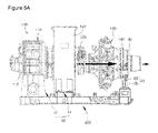
- the top of the moving panel 29 is fastened to the first moving part 22 through the connection member 25 so as to be positioned in a direction crossing the first moving part 22, and the bottom of the moving panel 29 is mounted on a base member 27 through a mounting member 28 mounted on the base frame 200. That is, when the gas turbine thermally expands in the axial direction, the moving panel 29 is deformed along the axial direction so as to reduce or minimize the occurrence of stress ( FIG. 5A ).
- the connection member 25 includes a horizontal plate 25a, a first fastening piece 25b, and a second fastening piece 25c.
- the horizontal plate 25a has a plate shape
- the first fastening piece 25b is formed on the top surface of the horizontal plate 25a and fastened to the support panel 24 through a bolt and nut
- the second fastening piece 25c is formed on the bottom surface of the horizontal plate 25a and fastened to the moving panel 29 through a bolt and nut.
- the first and second fastening pieces 25b and 25c are disposed to cross each other at right angles. That is, the connection member 25 serves to fasten the support panel and the moving panel such that the support panel and the moving panel are deformed in the circumferential direction and the axial direction, respectively, in a state where the support panel and the moving panel are connected to each other.
- the height adjusting pad 30 may be formed of an elastic material. When the gas turbine is deformed in a vertical direction (based on Fig. 2 ) during the thermal expansion, the height adjusting pad 30 may be deformed to correspond to such a deformation. Thus, the occurrence of stress in the vertical direction may be minimized.
- one height adjusting pad is included. However, a plurality of height adjusting pads may be included.
- the base member 27 includes a flange 27a and a protruding mounting surface 27b.
- the flange 27a is mounted on the base frame 200 through bolts and nuts, and the protruding mounting surface 27b is formed to protrude from the top surface of the flange 27a such that the mounting member 28 is fastened to the protruding mounting surface 27b.
- the protruding mounting surface 27b is formed to protrude from the top surface of the flange 27a such that the height is more smoothly adjusted and the stress reduction effect is increased.
- the mounting member 28 includes a mounting plate 28a and a mounting piece 28b.
- the mounting plate 28a is fastened to the protruding mounting surface 27b through bolts and nuts, and the mounting piece 28b is formed on the top surface of the mounting plate 28a and fastened to the bottom of the moving panel 29 through bolts and nuts.
- the support panel 24 and the moving panel 29 may be formed of an elastic material such as spring steel, which has a high supporting force while easily deformed according to the thermal expansion of the gas turbine.
- each of the support panel 24 and the moving panel 29 is provided as one panel. Depending on cases, however, a plurality of panels may be stacked. Such a structure may stably support the gas turbine while having a sufficient elasticity.
- the absorbing member 20 is provided as a pair of absorbing members. Between the pair of absorbing members, a limitation member 40 may be provided to limit the deformation of the gas turbine. The limitation member 40 may be positioned to deviate from the axial center of the gas turbine in the radial direction.
- the limitation member 40 comes in contact with the gas turbine so as to limit additional thermal expansion.
- the gas turbine may be stably supported regardless of the thermal expansion of the gas turbine.
- the limitation member 40 does not coincide with the axial center of the gas turbine, but is positioned offset or deviating from the axial center of the gas turbine. Thus, even when the gas turbine is distorted by irregular thermal expansion, the limitation member 40 may limit the distortion within a particular (or, alternatively a predetermined) range.
- the limitation member 40 includes a mounting flange 42 and a pair of movement limitation posts 46.
- the mounting flange 42 is mounted on the base frame 200 through bolts and nuts, and the pair of movement limitation posts 46 are formed at both sides of the mounting flange 42 such that a movement prevention bump 44 (see FIG. 4 ) mounted on the turbine housing 142 is inserted therebetween.
- the pair of movement limitation posts 46 are disposed to be separated at a desired (or, a alternatively predetermined) distance from each other.
- the movement prevention bump mounted on the turbine housing is not fastened to the movement limitation posts, but separated from the movement limitation posts by a desired (or, alternatively a predetermined) distance provided therebetween.
- the movement prevent bump may prevent additional thermal expansion of the gas turbine while coming in contact with any one or both of the movement limitation posts.
- the movement limitation posts 46 may include a pad 46a provided on an upper inner surface thereof.
- the pad 46a serves to reduce friction when the movement limitation posts 46 are contacted with the movement prevention bump 44 provided in the gas turbine.
- the top of the movement limitation post 46 may be included toward the axial center of the gas turbine, because the top of the movement limitation post 46 does not coincide with the axial center, but is positioned to deviate from the axial center. At this time, since the top of the movement limitation post 46 is inclined toward the axial center, a larger restoring force may be applied to the gas turbine than when the gas turbine is distorted.
Landscapes
- Engineering & Computer Science (AREA)
- General Engineering & Computer Science (AREA)
- Chemical & Material Sciences (AREA)
- Combustion & Propulsion (AREA)
- Mechanical Engineering (AREA)
- Turbine Rotor Nozzle Sealing (AREA)
- Structures Of Non-Positive Displacement Pumps (AREA)
- Supports For Pipes And Cables (AREA)
Abstract
Description
- Some example embodiments relate to a supporting device for a gas turbine and/or a gas turbine with the same, and more particularly, to a supporting device for stably supporting a gas turbine in an installation place and/or a gas turbine with the same.
- In general, a gas turbine includes a compressor, a combustor, and a turbine. The compressor sucks external air, compresses the sucked air at high temperature and high pressure, and then transfers the compressed air to the combustor. The combustor mixes the introduced compressed air with fuel, combusts the mixture to generate high-temperature and high-pressure gas, and transfers the generated high-temperature and high-pressure gas to the turbine.
- In this way, the high-temperature and high-pressure gas transferred from the combustor rotates a rotating shaft of the turbine while passing through a moving blade of the turbine, and drives a generator to generate power. Furthermore, a reducer for reducing a rotational force is connected to the front of one side of the compressor, and components included in the gas turbine are supported by the top of a base frame.
- Since the gas turbine is exposed to high-temperature combustion gas during operation, thermal expansion inevitably occurs. Thus, the base frame should absorb the thermal expansion of the gas turbine. In this case, the structure of a supporting device for supporting the gas turbine may become complex.
- At least one embodiment relates to a supporting device for a gas turbine.
- In one embodiment, the supporting device for a gas turbine includes: a base frame; a fixing member installed on the base frame so as to support one end of a gas turbine; and an absorbing member installed on the base frame so as to support the other end of the gas turbine, and having lower stiffness than the fixing member so as to deform in first and second directions when the gas turbine thermally expands.
- The gas turbine may include a reducer housing and a compressor suction duct, and the fixing member may include a first fixing member configured to fasten to the reducer housing and a second fixing member configured to fasten to the compressor suction duct.
- The first direction extends along a direction parallel to a longitudinal section of the gas turbine, and the second direction extends along an axial direction of the gas turbine.
- The gas turbine may include a turbine housing, and the absorbing member may include a first moving part configured to fasten to the turbine housing and deform along the first direction and a second moving part configured to deform along the second direction.
- The second moving part may be inclined toward the fixing member. Thus, when the gas turbine thermally expands in the axial direction, the second moving part may be positioned to cross the base frame at right angles.
- The first moving part may include a plate-shaped support panel parallel to the second direction.
- The second moving part may include a plate-shaped moving panel having a top and a bottom, the top is fastened to the first moving member through a connection member and the bottom is fastened to the base frame through a base member and a mounting member, and the moving panel is perpendicular to the support panel.
- The connection member may include: a horizontal plate; a first fastening piece formed on a top surface of the horizontal plate and fastened to the support panel; and a second fastening piece formed on a bottom surface of the horizontal plate and fastened to the moving panel.
- The supporting device may further include one or more height adjusting pads provided between the base member and the mounting member.
- The base member may include a flange mounted on the base frame and a protruding mounting surface protruding from a top surface of the flange such that the mounting member is fastened to the protruding mounting surface.
- The mounting member may include a mounting plate fastened to the protruding mounting surface and a mounting piece fastened to the bottom of the moving panel.
- The absorbing member may include a pair of absorbing members, and a limitation member provided between the pair of absorbing members so as to limit thermal expansion of the gas turbine.
- When the thermal expansion of the gas turbine becomes larger than a value, the limitation member may come in contact with the surface of the gas turbine so as to limit the thermal expansion of the gas turbine.
- The limitation member may be positioned offset from the shaft center of the gas turbine.
- The limitation member may include a mounting flange mounted on the base frame and a pair of movement limitation posts disposed on the mounting flange.
- The movement limitation posts may have a pad provided on an upper inner surface thereof.
- The top portion of the movement limitation post is formed to have a slope toward the axial center.
- At least one embodiment relates to a gas turbine supported by a supporting device as described above.
- It is to be understood that both the foregoing general description and the following detailed description of the present invention are exemplary and explanatory and are intended to provide further explanation of the invention as claimed.
- The above and other objects, features and other advantages of the present invention will be more clearly understood from the following detailed description taken in conjunction with the accompanying drawings, in which:
-
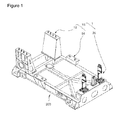
Fig. 1 is a schematic perspective view of a supporting device for a gas turbine in accordance with an embodiment; -
Fig. 2 is a expanded perspective view of an absorbing member of the supporting device illustrated inFig. 1 ; -
Fig. 3 is a front view of a gas turbine having the supporting device illustrated inFig. 1 ; -
Fig. 4 is a side view illustrating one side surface of the gas turbine illustrated inFig. 3 ; -
Fig. 5A is a front view illustrating a state in which the gas turbine thermally expands in an axial direction; and -
Fig. 5B is a side view illustrating a state in which the gas turbine thermally expands in a circumferential direction. - The inventive concepts now will be described more fully hereinafter with reference to the accompanying drawings, in which embodiments of the invention are shown. This invention may, however, be embodied in many different forms and should not be construed as limited to the embodiments set forth herein. Rather, these embodiments are provided so that this disclosure will be thorough and complete, and will fully convey the scope of the invention to those skilled in the art. In the drawings, the size and relative sizes of layers and regions may be exaggerated for clarity. Like numbers refer to like elements throughout.
- It will be understood that when an element is referred to as being "connected" or "coupled" to another element, it can be directly connected or coupled to the other element or intervening elements may be present. In contrast, when an element is referred to as being "directly connected" or "directly coupled" to another element, there are no intervening elements present. As used herein, the term "and/or" includes any and all combinations of one or more of the associated listed items and may be abbreviated as "/".
- It will be understood that, although the terms first, second, etc. may be used herein to describe various elements, these elements should not be limited by these terms. These terms are only used to distinguish one element from another. For example, a first signal could be termed a second signal, and, similarly, a second signal could be termed a first signal without departing from the teachings of the disclosure.
- The terminology used herein is for the purpose of describing particular embodiments only and is not intended to be limiting of the invention. As used herein, the singular forms "a", "an" and "the" are intended to include the plural forms as well, unless the context clearly indicates otherwise. It will be further understood that the terms "comprises" and/or "comprising," or "includes" and/or "including" when used in this specification, specify the presence of stated features, regions, integers, steps, operations, elements, and/or components, but do not preclude the presence or addition of one or more other features, regions, integers, steps, operations, elements, components, and/or groups thereof.
- Unless otherwise defined, all terms (including technical and scientific terms) used herein have the same meaning as commonly understood by one of ordinary skill in the art to which this invention belongs. It will be further understood that terms, such as those defined in commonly used dictionaries, should be interpreted as having a meaning that is consistent with their meaning in the context of the relevant art and/or the present disclosure, and will not be interpreted in an idealized or overly formal sense unless expressly so defined herein.
- A supporting device for a gas turbine and a gas turbine with the same according to example embodiments will be described below in more detail with reference to the accompanying drawings.
- Referring to
Figs. 1 to 3 , a supporting device for a gas turbine according to an embodiment includes abase frame 200 and a supporting unit 1 capable of accepting thermal expansion which occurs in a circumferential direction and an axial direction, due to thermal expansion of agas turbine 100. Thegas turbine 100 includes areducer 110, acompressor 120, acombustor 130, and aturbine 140, which are sequentially arranged. - The gas turbine to which the present invention may be applied is not limited to that illustrated in the drawings, and the present invention may be applied to any type of gas turbine having an outer shape which may be supported by the supporting unit 1.
- The supporting unit 1 includes a
fixing member 10 and an absorbingmember 20 installed on thebase frame 200. The fixingmember 10 is installed on thebase frame 200 so as to be positioned at the front end of thegas turbine 100, that is, at the side of thereducer 110. The absorbingmember 20 is installed on thebase frame 200 so as to be positioned at the rear end of thegas turbine 100, that is, at the side of theturbine 140. The absorbingmember 20 is formed to have lower stiffness than the fixingmember 10. Thus, when the gas turbine thermally expands, the fixingmember 10 maintains almost the same shape as the gas turbine is not operated, but the absorbingmember 20 is deformed by an amount corresponding to the thermal expansion of the gas turbine. - That is, supporting members are provided at the front and rear of the gas turbine, and one of the supporting members is formed to have a flexible structure. Thus, the supporting unit may reduce or substantially prevent the occurrence of excessive stress caused by thermal expansion.
- Therefore, in order to reduce or minimize deformation even though the gas turbine thermally expands, the fixing
member 10 is formed to have high stiffness, using a plurality of panels constructed in a rectangular box shape. Specifically, the fixingmember 10 includes a first fixingmember 12 and a second fixingmember 14. The first fixingmember 12 has a flange coupled to both side ends of areducer housing 112 of thegas turbine 100, and the second fixingmember 14 has a flange coupled to both side ends of asuction duct 122 of thecompressor 120. - The second fixing
member 14 is disposed at a position separated from the first fixingmember 12 along the rear of the gas turbine. Furthermore, the first and second fixingmembers - Thus, the reducer of the gas turbine and the suction duct of the compressor, which are positioned at the front of the base frame, are reliably supported by the first and second fixing members. When the gas turbine thermally expands, the positions of a leading end and a tail end of the gas turbine are change by the thermal expansion, but the positions of connections between the first and second fixing members and the gas turbine are almost constantly maintained.
- The absorbing
member 20 includes a first movingpart 22 and a second movingpart 26. The first movingpart 22 is fastened to both side ends of aturbine housing 142 of thegas turbine 100 and deformed (or flexed) to correspond to radial expansion of theturbine housing 142, caused by the thermal expansion, and the second movingpart 26 is disposed under the first movingpart 22 and deformed (or flexed) to correspond to axial expansion of thegas turbine 100. - In other words, the absorbing
member 20 has such a structure that is deformed in two different directions so as to correspond to both of the radial expansion and the axial expansion of thegas turbine 100. In the illustrated example, the two directions are set to the radial direction and the axial direction. However, the example embodiments are not limited thereto, but the two directions may be set to two arbitrary directions. The thermal expansion in the circumferential direction and the thermal expansion in the axial direction may be dealt with by one member having a simple structure, instead of separate members. Thus, the installation and maintenance may be easily conducted. - The second moving
part 26 may be disposed to be inclined toward the front of thegas turbine 100. Thus, when deformation occurs in the axial direction due to the thermal expansion, the second movingpart 26 may not be inclined but disposed in a direction which is roughly perpendicular to the base frame. That is, as the second movingpart 26 is disposed to be inclined toward the front of thegas turbine 100 through data, (e.g. previously calculated in consideration of the thermal expansion in the axial direction, provided through measurement, determined by empirical study, etc.) the second movingpart 26 may be positioned roughly perpendicular to the base frame. Such a structure may stably support the gas turbine even in a state where the second movingpart 26 is deformed due to the thermal expansion. - The first moving
part 22 includes asupport panel 24 aligned along the axial direction of the gas turbine. The top of thesupport panel 24 is fastened and fixed to theturbine housing 142 through afastening bracket 23, and the bottom of thesupport panel 24 is fastened to the second movingpart 26 through aconnection member 25 so as to be positioned in a direction crossing the second movingpart 26. Thus, when the gas turbine thermally expands in the radial direction, thesupport panel 24 is deformed along the radial direction of the gas turbine so as to reduce or minimize the occurrence of stress caused by the thermal expansion (FIG. 5B ). - Furthermore, when the fastening bracket is fastened and fixed to the top of the support panel, a separate member may be fastened and fixed together, depending on space or assembly. Depending on cases, the fastening bracket may be omitted, and the top of the support panel may be directly fastened to the turbine housing.
- The second moving
part 26 includes a movingpanel 29 aligned along the radial direction of the gas turbine. The top of the movingpanel 29 is fastened to the first movingpart 22 through theconnection member 25 so as to be positioned in a direction crossing the first movingpart 22, and the bottom of the movingpanel 29 is mounted on abase member 27 through a mountingmember 28 mounted on thebase frame 200. That is, when the gas turbine thermally expands in the axial direction, the movingpanel 29 is deformed along the axial direction so as to reduce or minimize the occurrence of stress (FIG. 5A ). - The
connection member 25 includes ahorizontal plate 25a, afirst fastening piece 25b, and asecond fastening piece 25c. Thehorizontal plate 25a has a plate shape, thefirst fastening piece 25b is formed on the top surface of thehorizontal plate 25a and fastened to thesupport panel 24 through a bolt and nut, and thesecond fastening piece 25c is formed on the bottom surface of thehorizontal plate 25a and fastened to the movingpanel 29 through a bolt and nut. The first andsecond fastening pieces connection member 25 serves to fasten the support panel and the moving panel such that the support panel and the moving panel are deformed in the circumferential direction and the axial direction, respectively, in a state where the support panel and the moving panel are connected to each other. - Between the
base member 27 and the mountingmember 28, one or moreheight adjusting pads 30 may be provided. Theheight adjusting pad 30 may be formed of an elastic material. When the gas turbine is deformed in a vertical direction (based onFig. 2 ) during the thermal expansion, theheight adjusting pad 30 may be deformed to correspond to such a deformation. Thus, the occurrence of stress in the vertical direction may be minimized. In the illustrated example, one height adjusting pad is included. However, a plurality of height adjusting pads may be included. - The
base member 27 includes aflange 27a and a protruding mountingsurface 27b. Theflange 27a is mounted on thebase frame 200 through bolts and nuts, and the protruding mountingsurface 27b is formed to protrude from the top surface of theflange 27a such that the mountingmember 28 is fastened to the protruding mountingsurface 27b. At this time, the protruding mountingsurface 27b is formed to protrude from the top surface of theflange 27a such that the height is more smoothly adjusted and the stress reduction effect is increased. - The mounting
member 28 includes a mountingplate 28a and a mountingpiece 28b. The mountingplate 28a is fastened to the protruding mountingsurface 27b through bolts and nuts, and the mountingpiece 28b is formed on the top surface of the mountingplate 28a and fastened to the bottom of the movingpanel 29 through bolts and nuts. - The
support panel 24 and the movingpanel 29 may be formed of an elastic material such as spring steel, which has a high supporting force while easily deformed according to the thermal expansion of the gas turbine. - In the illustrated example, each of the
support panel 24 and the movingpanel 29 is provided as one panel. Depending on cases, however, a plurality of panels may be stacked. Such a structure may stably support the gas turbine while having a sufficient elasticity. - The absorbing
member 20 is provided as a pair of absorbing members. Between the pair of absorbing members, alimitation member 40 may be provided to limit the deformation of the gas turbine. Thelimitation member 40 may be positioned to deviate from the axial center of the gas turbine in the radial direction. - Specifically, when the gas turbine thermally expands in a particular (or, alternatively a predetermined) range or more, the
limitation member 40 comes in contact with the gas turbine so as to limit additional thermal expansion. Thus, during operation, the gas turbine may be stably supported regardless of the thermal expansion of the gas turbine. - Furthermore, the
limitation member 40 does not coincide with the axial center of the gas turbine, but is positioned offset or deviating from the axial center of the gas turbine. Thus, even when the gas turbine is distorted by irregular thermal expansion, thelimitation member 40 may limit the distortion within a particular (or, alternatively a predetermined) range. - The
limitation member 40 includes a mountingflange 42 and a pair of movement limitation posts 46. The mountingflange 42 is mounted on thebase frame 200 through bolts and nuts, and the pair of movement limitation posts 46 are formed at both sides of the mountingflange 42 such that a movement prevention bump 44 (seeFIG. 4 ) mounted on theturbine housing 142 is inserted therebetween. The pair of movement limitation posts 46 are disposed to be separated at a desired (or, a alternatively predetermined) distance from each other. - That is, the movement prevention bump mounted on the turbine housing is not fastened to the movement limitation posts, but separated from the movement limitation posts by a desired (or, alternatively a predetermined) distance provided therebetween. When the thermal expansion of the gas turbine becomes equal to or more than a particular (or, alternatively a predetermined) amount, the movement prevent bump may prevent additional thermal expansion of the gas turbine while coming in contact with any one or both of the movement limitation posts.
- Furthermore, the movement limitation posts 46 may include a
pad 46a provided on an upper inner surface thereof. Thepad 46a serves to reduce friction when the movement limitation posts 46 are contacted with themovement prevention bump 44 provided in the gas turbine. - In addition, the top of the
movement limitation post 46 may be included toward the axial center of the gas turbine, because the top of themovement limitation post 46 does not coincide with the axial center, but is positioned to deviate from the axial center. At this time, since the top of themovement limitation post 46 is inclined toward the axial center, a larger restoring force may be applied to the gas turbine than when the gas turbine is distorted. - While the present invention has been described with respect to example embodiments, it will be apparent to those skilled in the art that various changes and modifications may be made without departing from the spirit and scope of the invention as defined in the following claims.
Claims (15)
- A supporting device for a gas turbine, comprising:a base frame (200);a fixing member (10) installed on the base frame (200) so as to support one end of a gas turbine; andan absorbing member (20) installed on the base frame (200) so as to support the other end of the gas turbine, and having lower stiffness than the fixing member (10) so as to deform in first and second directions when the gas turbine thermally expands.
- The supporting device according to claim 1, wherein the fixing member (10) comprises:a first fixing member (12) configured to fasten to a reducer housing (112) of the gas turbine; anda second fixing member (14) configured to fasten to a compressor suction duct (122) of the gas turbine.
- The supporting device according to claim 1 or 2, wherein the first direction extends along a direction parallel to a longitudinal section of the gas turbine, and the second direction extends along a radial direction of the gas turbine.
- The supporting device according to any one of the preceding claims, wherein the absorbing member (20) comprises:a first moving part (22) configured to fasten to a turbine housing (142) of the gas turbine and deform along the first direction; anda second moving part (26) configured to deform along the second direction.
- The supporting device according to claim 4, wherein the second moving part (26) is inclined toward the fixing member (10).
- The supporting device according to claim 4 or 5, wherein the first moving part (22) comprises a plate-shaped support panel (24) parallel to the second direction.
- The supporting device according to claim 6, wherein the second moving part (26) comprises a plate-shaped moving panel (29) having a top and a bottom, the top is fastened to the first moving part (22) through a connection member (25) and the bottom is fastened to the base frame (200) through a base member (27) and a mounting member (28), and the moving panel (29) is perpendicular to the support panel (24).
- The supporting device according to claim 7, wherein the connection member (25) comprises:a horizontal plate (25 a);a first fastening piece (25b) formed on a top surface of the horizontal plate (25a) and fastened to the support panel (24); anda second fastening piece (25c) formed on a bottom surface of the horizontal plate (25a) and fastened to the moving panel (29).
- The supporting device according to claim 7 or 8, further comprising:one or more height adjusting pads (30) provided between the base member (27) and the mounting member (28).
- The supporting device according to any one of the preceding claims 7, 8 or 9, wherein the base member (27) comprises:a flange (27a) mounted on the base frame (200); anda protruding mounting surface (27b) protruding from a top surface of the flange (27a) such that the mounting member (28) is fastened to the protruding mounting surface (27b).
- The supporting device according to claim 10, wherein the mounting member (28) comprises:a mounting plate (28a) fastened to the protruding mounting surface (27b); anda mounting piece (28b) fastened to the bottom of the moving panel (29).
- The supporting device according to any one of the preceding claims, wherein the absorbing member (20) comprises:a pair of absorbing members (20); anda limitation member (40) provided between the pair of absorbing member (20) so as to limit thermal expansion of the gas turbine.
- The supporting device according to claim 12, wherein when the thermal expansion of the gas turbine becomes larger than a value, the limitation member (40) comes in contact with the surface of the gas turbine so as to limit the thermal expansion of the gas turbine.
- The supporting device according to claim 12 or 13, wherein the limitation member (40) is positioned offset from a shaft center of the gas turbine.
- The supporting device according to any one of the preceding claims 12, 13 or 14, wherein the limitation member (40) comprises:a mounting flange (42) mounted on the base frame (200); anda pair of movement limitation posts (46) disposed on the mounting flange (42).
Applications Claiming Priority (1)
| Application Number | Priority Date | Filing Date | Title |
|---|---|---|---|
| KR20130030902A KR101482573B1 (en) | 2013-03-22 | 2013-03-22 | Supporting device for a gas turbine |
Publications (3)
| Publication Number | Publication Date |
|---|---|
| EP2781700A2 true EP2781700A2 (en) | 2014-09-24 |
| EP2781700A3 EP2781700A3 (en) | 2017-10-11 |
| EP2781700B1 EP2781700B1 (en) | 2021-05-26 |
Family
ID=50336214
Family Applications (1)
| Application Number | Title | Priority Date | Filing Date |
|---|---|---|---|
| EP14161105.3A Active EP2781700B1 (en) | 2013-03-22 | 2014-03-21 | Supporting device for gas turbine |
Country Status (3)
| Country | Link |
|---|---|
| US (1) | US9752505B2 (en) |
| EP (1) | EP2781700B1 (en) |
| KR (1) | KR101482573B1 (en) |
Cited By (2)
| Publication number | Priority date | Publication date | Assignee | Title |
|---|---|---|---|---|
| WO2017008940A1 (en) * | 2015-07-15 | 2017-01-19 | Siemens Aktiengesellschaft | Exhaust-steam casing for a steam turbine and assembly system |
| EP3392475A1 (en) * | 2017-04-19 | 2018-10-24 | Siemens Aktiengesellschaft | Flexible turbine support |
Families Citing this family (12)
| Publication number | Priority date | Publication date | Assignee | Title |
|---|---|---|---|---|
| KR101860982B1 (en) * | 2015-07-14 | 2018-05-24 | 두산중공업 주식회사 | Combustor supporting device of gas turbine |
| CN107355508B (en) * | 2017-09-07 | 2023-07-14 | 东方电气(德阳)电动机技术有限责任公司 | Vibration reduction support and motor adopting same |
| KR20190032846A (en) | 2017-09-20 | 2019-03-28 | 두산중공업 주식회사 | Structure for supporting turbine, turbine and gas turbine using the same |
| US11897116B2 (en) * | 2017-10-27 | 2024-02-13 | Oshkosh Defense, Llc | Engine stand |
| ES1203662Y (en) * | 2017-12-18 | 2018-04-18 | Nordex Energy Spain Sau | TRANSPORTATION OF A SUBCONJUNTO OF A POWER SUPPLY TRAIN AN AEROGENERATOR |
| US10288212B1 (en) * | 2018-02-19 | 2019-05-14 | Mantosh Isanchandra Bhattacharya | Tunable support frame structure for rotating machines |
| KR102405427B1 (en) * | 2018-03-05 | 2022-06-07 | 한화에어로스페이스 주식회사 | Supporting apparatus for gas turbine |
| CN109026208B (en) * | 2018-09-21 | 2024-02-06 | 中国长江动力集团有限公司 | Turbine chassis and turbine |
| CN114278403B (en) * | 2021-11-18 | 2024-05-28 | 中国长江动力集团有限公司 | Elastic support plate |
| KR200498168Y1 (en) * | 2021-12-24 | 2024-07-19 | 두산에너빌리티 (주) | Supporting device for gas turbine transport |
| KR102797890B1 (en) * | 2022-12-26 | 2025-04-17 | 두산에너빌리티 주식회사 | Supporting device for gas turbine |
| KR102895868B1 (en) * | 2023-04-17 | 2025-12-03 | 두산에너빌리티 주식회사 | Gas turbine supporting apparatus |
Family Cites Families (26)
| Publication number | Priority date | Publication date | Assignee | Title |
|---|---|---|---|---|
| US3188808A (en) * | 1962-12-03 | 1965-06-15 | Cooper Bessemer Corp | Gas turbine thrust compensating device |
| US3268093A (en) * | 1964-03-18 | 1966-08-23 | Gen Electric | Object handling system |
| US4053189A (en) * | 1976-06-17 | 1977-10-11 | United Technologies Corporation | Turbine construction |
| US4295257A (en) * | 1980-02-20 | 1981-10-20 | Strohs Robert F | Work stand for vertical turbine pumps |
| US4461455A (en) * | 1981-09-30 | 1984-07-24 | The Boeing Company | Aircraft engine lifting and positioning apparatus |
| US5575607A (en) * | 1994-11-02 | 1996-11-19 | United Technologies Corporation | Jet engine transport vehicle lift system and a build cell |
| US5509782A (en) * | 1995-03-02 | 1996-04-23 | Dresser-Rand Company | Bearing case support |
| US5816367A (en) * | 1995-11-30 | 1998-10-06 | Stanley Aviation Corporation | Jet aircraft engine transport apparatus |
| US5722512A (en) * | 1995-11-30 | 1998-03-03 | Stanley Aviation Corporation | Jet aircraft engine shipping stand |
| US5645389A (en) * | 1995-11-30 | 1997-07-08 | Stanley Aviation Corporation | Shipping frame from fan section of aircraft engine |
| US5810558A (en) * | 1996-01-16 | 1998-09-22 | Dresser-Rand Company | Bearing case support arrangement |
| US6170141B1 (en) * | 1998-09-25 | 2001-01-09 | Stanley Aviation Corporation | Shipping system for jet aircraft engine and method of installing and removing jet aircraft engine |
| US7036318B1 (en) * | 2002-04-16 | 2006-05-02 | Altek Power Corporation | Gas turbine electric powerplant |
| US7552903B2 (en) * | 2005-12-13 | 2009-06-30 | Solar Turbines Incorporated | Machine mounting system |
| EP1996796B1 (en) * | 2006-03-17 | 2016-01-06 | Alstom Technology Ltd | Device and method for supporting a turbomachine |
| GB0613929D0 (en) * | 2006-07-13 | 2006-08-23 | Rolls Royce Plc | An engine core stand arrangement and method of removal and transportation of an engine core |
| US8083471B2 (en) * | 2007-01-22 | 2011-12-27 | General Electric Company | Turbine rotor support apparatus and system |
| JP4859688B2 (en) | 2007-01-30 | 2012-01-25 | 三菱重工業株式会社 | gas turbine |
| JP5161629B2 (en) * | 2008-03-28 | 2013-03-13 | 三菱重工業株式会社 | Turbine support structure and gas turbine |
| GB2460419B (en) * | 2008-05-29 | 2010-09-22 | Rolls Royce Plc | A cradle arrangement |
| GB2462405B (en) * | 2008-05-29 | 2010-09-08 | Rolls Royce Plc | A cradle arrangement |
| US7963542B2 (en) * | 2008-08-29 | 2011-06-21 | Solar Turbines Incorporated | Modular cart for a gas turbine engine |
| US20110016881A1 (en) * | 2009-07-21 | 2011-01-27 | Jose Luis Ruiz | Gas turbine with exhaust gas casing and method for producing a gas turbine |
| KR101504848B1 (en) * | 2011-03-31 | 2015-03-20 | 미츠비시 쥬고교 가부시키가이샤 | Steam turbine casing position adjusting apparatus |
| US8984730B2 (en) * | 2012-02-07 | 2015-03-24 | General Electric Company | System and method for rotating a turbine shell |
| US8851441B2 (en) * | 2012-05-17 | 2014-10-07 | Solar Turbine Inc. | Engine skid assembly |
-
2013
- 2013-03-22 KR KR20130030902A patent/KR101482573B1/en active Active
-
2014
- 2014-03-21 EP EP14161105.3A patent/EP2781700B1/en active Active
- 2014-03-21 US US14/221,725 patent/US9752505B2/en active Active
Non-Patent Citations (1)
| Title |
|---|
| None |
Cited By (3)
| Publication number | Priority date | Publication date | Assignee | Title |
|---|---|---|---|---|
| WO2017008940A1 (en) * | 2015-07-15 | 2017-01-19 | Siemens Aktiengesellschaft | Exhaust-steam casing for a steam turbine and assembly system |
| CN107849940A (en) * | 2015-07-15 | 2018-03-27 | 西门子公司 | Exhaust casings and mounting systems for steam turbines |
| EP3392475A1 (en) * | 2017-04-19 | 2018-10-24 | Siemens Aktiengesellschaft | Flexible turbine support |
Also Published As
| Publication number | Publication date |
|---|---|
| US9752505B2 (en) | 2017-09-05 |
| KR101482573B1 (en) | 2015-01-21 |
| KR20140115792A (en) | 2014-10-01 |
| US20140283529A1 (en) | 2014-09-25 |
| EP2781700B1 (en) | 2021-05-26 |
| EP2781700A3 (en) | 2017-10-11 |
Similar Documents
| Publication | Publication Date | Title |
|---|---|---|
| US9752505B2 (en) | Supporting device for gas turbine | |
| CN102224323B (en) | A turbomachine with a ring segment positioning member | |
| CA2663880C (en) | Compressor mounting system | |
| EP3358214A1 (en) | Base isolation unit and base isolation method | |
| JP2014043810A (en) | Support structure of electric motor, and compressor | |
| US10066552B2 (en) | One degree-of-constraint semi-fusible gearbox mounting link | |
| CN107002507B (en) | Multipoint Mounting System for Rotating Machinery | |
| US9010027B2 (en) | Panel attachment system and a method of using the same | |
| EP3088677A1 (en) | Quad-tab u-washer | |
| US10876430B2 (en) | Mount assembly | |
| EP2014878A2 (en) | Preloading brace for gas turbine engine transportation | |
| US11028732B2 (en) | High temperature panel damper for sheet metal structures | |
| CN109763896B (en) | Heat insulation piece fixing device | |
| US8267660B2 (en) | Fan module for dissipating heat | |
| US9210827B2 (en) | Automation device having a heatsink | |
| EP3336406B1 (en) | Mounting system for rotating machinery | |
| EP3392475A1 (en) | Flexible turbine support | |
| US9422956B2 (en) | Panel mounting arrangement | |
| CN204943716U (en) | Damping assembly and the air-conditioner with it | |
| JP4763823B2 (en) | Air conditioner outdoor unit and method of manufacturing the same | |
| KR101833417B1 (en) | Motor supporting structure for reducing vibration by thermal stain | |
| US20120128464A1 (en) | Fan assembly | |
| JP2022180870A (en) | Vibration control device | |
| US20190093516A1 (en) | Mount assembly | |
| CN110379320A (en) | A kind of LED display anti-collision protection structure and LED display |
Legal Events
| Date | Code | Title | Description |
|---|---|---|---|
| PUAI | Public reference made under article 153(3) epc to a published international application that has entered the european phase |
Free format text: ORIGINAL CODE: 0009012 |
|
| 17P | Request for examination filed |
Effective date: 20140321 |
|
| AK | Designated contracting states |
Kind code of ref document: A2 Designated state(s): AL AT BE BG CH CY CZ DE DK EE ES FI FR GB GR HR HU IE IS IT LI LT LU LV MC MK MT NL NO PL PT RO RS SE SI SK SM TR |
|
| AX | Request for extension of the european patent |
Extension state: BA ME |
|
| PUAL | Search report despatched |
Free format text: ORIGINAL CODE: 0009013 |
|
| AK | Designated contracting states |
Kind code of ref document: A3 Designated state(s): AL AT BE BG CH CY CZ DE DK EE ES FI FR GB GR HR HU IE IS IT LI LT LU LV MC MK MT NL NO PL PT RO RS SE SI SK SM TR |
|
| AX | Request for extension of the european patent |
Extension state: BA ME |
|
| RIC1 | Information provided on ipc code assigned before grant |
Ipc: F01D 25/28 20060101AFI20170904BHEP Ipc: F02C 7/32 20060101ALI20170904BHEP Ipc: F02C 7/20 20060101ALI20170904BHEP |
|
| RAP1 | Party data changed (applicant data changed or rights of an application transferred) |
Owner name: DOOSAN HEAVY INDUSTRIES & CONSTRUCTION CO., LTD. |
|
| STAA | Information on the status of an ep patent application or granted ep patent |
Free format text: STATUS: EXAMINATION IS IN PROGRESS |
|
| 17Q | First examination report despatched |
Effective date: 20200213 |
|
| GRAP | Despatch of communication of intention to grant a patent |
Free format text: ORIGINAL CODE: EPIDOSNIGR1 |
|
| STAA | Information on the status of an ep patent application or granted ep patent |
Free format text: STATUS: GRANT OF PATENT IS INTENDED |
|
| INTG | Intention to grant announced |
Effective date: 20210112 |
|
| GRAS | Grant fee paid |
Free format text: ORIGINAL CODE: EPIDOSNIGR3 |
|
| GRAA | (expected) grant |
Free format text: ORIGINAL CODE: 0009210 |
|
| STAA | Information on the status of an ep patent application or granted ep patent |
Free format text: STATUS: THE PATENT HAS BEEN GRANTED |
|
| AK | Designated contracting states |
Kind code of ref document: B1 Designated state(s): AL AT BE BG CH CY CZ DE DK EE ES FI FR GB GR HR HU IE IS IT LI LT LU LV MC MK MT NL NO PL PT RO RS SE SI SK SM TR |
|
| REG | Reference to a national code |
Ref country code: GB Ref legal event code: FG4D |
|
| REG | Reference to a national code |
Ref country code: CH Ref legal event code: EP |
|
| REG | Reference to a national code |
Ref country code: AT Ref legal event code: REF Ref document number: 1396420 Country of ref document: AT Kind code of ref document: T Effective date: 20210615 |
|
| REG | Reference to a national code |
Ref country code: DE Ref legal event code: R096 Ref document number: 602014077665 Country of ref document: DE |
|
| REG | Reference to a national code |
Ref country code: IE Ref legal event code: FG4D |
|
| REG | Reference to a national code |
Ref country code: LT Ref legal event code: MG9D |
|
| REG | Reference to a national code |
Ref country code: AT Ref legal event code: MK05 Ref document number: 1396420 Country of ref document: AT Kind code of ref document: T Effective date: 20210526 |
|
| PG25 | Lapsed in a contracting state [announced via postgrant information from national office to epo] |
Ref country code: HR Free format text: LAPSE BECAUSE OF FAILURE TO SUBMIT A TRANSLATION OF THE DESCRIPTION OR TO PAY THE FEE WITHIN THE PRESCRIBED TIME-LIMIT Effective date: 20210526 Ref country code: AT Free format text: LAPSE BECAUSE OF FAILURE TO SUBMIT A TRANSLATION OF THE DESCRIPTION OR TO PAY THE FEE WITHIN THE PRESCRIBED TIME-LIMIT Effective date: 20210526 Ref country code: BG Free format text: LAPSE BECAUSE OF FAILURE TO SUBMIT A TRANSLATION OF THE DESCRIPTION OR TO PAY THE FEE WITHIN THE PRESCRIBED TIME-LIMIT Effective date: 20210826 Ref country code: FI Free format text: LAPSE BECAUSE OF FAILURE TO SUBMIT A TRANSLATION OF THE DESCRIPTION OR TO PAY THE FEE WITHIN THE PRESCRIBED TIME-LIMIT Effective date: 20210526 Ref country code: LT Free format text: LAPSE BECAUSE OF FAILURE TO SUBMIT A TRANSLATION OF THE DESCRIPTION OR TO PAY THE FEE WITHIN THE PRESCRIBED TIME-LIMIT Effective date: 20210526 |
|
| REG | Reference to a national code |
Ref country code: NL Ref legal event code: MP Effective date: 20210526 |
|
| PG25 | Lapsed in a contracting state [announced via postgrant information from national office to epo] |
Ref country code: GR Free format text: LAPSE BECAUSE OF FAILURE TO SUBMIT A TRANSLATION OF THE DESCRIPTION OR TO PAY THE FEE WITHIN THE PRESCRIBED TIME-LIMIT Effective date: 20210827 Ref country code: LV Free format text: LAPSE BECAUSE OF FAILURE TO SUBMIT A TRANSLATION OF THE DESCRIPTION OR TO PAY THE FEE WITHIN THE PRESCRIBED TIME-LIMIT Effective date: 20210526 Ref country code: IS Free format text: LAPSE BECAUSE OF FAILURE TO SUBMIT A TRANSLATION OF THE DESCRIPTION OR TO PAY THE FEE WITHIN THE PRESCRIBED TIME-LIMIT Effective date: 20210926 Ref country code: SE Free format text: LAPSE BECAUSE OF FAILURE TO SUBMIT A TRANSLATION OF THE DESCRIPTION OR TO PAY THE FEE WITHIN THE PRESCRIBED TIME-LIMIT Effective date: 20210526 Ref country code: RS Free format text: LAPSE BECAUSE OF FAILURE TO SUBMIT A TRANSLATION OF THE DESCRIPTION OR TO PAY THE FEE WITHIN THE PRESCRIBED TIME-LIMIT Effective date: 20210526 Ref country code: PT Free format text: LAPSE BECAUSE OF FAILURE TO SUBMIT A TRANSLATION OF THE DESCRIPTION OR TO PAY THE FEE WITHIN THE PRESCRIBED TIME-LIMIT Effective date: 20210927 Ref country code: PL Free format text: LAPSE BECAUSE OF FAILURE TO SUBMIT A TRANSLATION OF THE DESCRIPTION OR TO PAY THE FEE WITHIN THE PRESCRIBED TIME-LIMIT Effective date: 20210526 Ref country code: NO Free format text: LAPSE BECAUSE OF FAILURE TO SUBMIT A TRANSLATION OF THE DESCRIPTION OR TO PAY THE FEE WITHIN THE PRESCRIBED TIME-LIMIT Effective date: 20210826 |
|
| PG25 | Lapsed in a contracting state [announced via postgrant information from national office to epo] |
Ref country code: NL Free format text: LAPSE BECAUSE OF FAILURE TO SUBMIT A TRANSLATION OF THE DESCRIPTION OR TO PAY THE FEE WITHIN THE PRESCRIBED TIME-LIMIT Effective date: 20210526 |
|
| PG25 | Lapsed in a contracting state [announced via postgrant information from national office to epo] |
Ref country code: RO Free format text: LAPSE BECAUSE OF FAILURE TO SUBMIT A TRANSLATION OF THE DESCRIPTION OR TO PAY THE FEE WITHIN THE PRESCRIBED TIME-LIMIT Effective date: 20210526 Ref country code: ES Free format text: LAPSE BECAUSE OF FAILURE TO SUBMIT A TRANSLATION OF THE DESCRIPTION OR TO PAY THE FEE WITHIN THE PRESCRIBED TIME-LIMIT Effective date: 20210526 Ref country code: SM Free format text: LAPSE BECAUSE OF FAILURE TO SUBMIT A TRANSLATION OF THE DESCRIPTION OR TO PAY THE FEE WITHIN THE PRESCRIBED TIME-LIMIT Effective date: 20210526 Ref country code: SK Free format text: LAPSE BECAUSE OF FAILURE TO SUBMIT A TRANSLATION OF THE DESCRIPTION OR TO PAY THE FEE WITHIN THE PRESCRIBED TIME-LIMIT Effective date: 20210526 Ref country code: EE Free format text: LAPSE BECAUSE OF FAILURE TO SUBMIT A TRANSLATION OF THE DESCRIPTION OR TO PAY THE FEE WITHIN THE PRESCRIBED TIME-LIMIT Effective date: 20210526 Ref country code: CZ Free format text: LAPSE BECAUSE OF FAILURE TO SUBMIT A TRANSLATION OF THE DESCRIPTION OR TO PAY THE FEE WITHIN THE PRESCRIBED TIME-LIMIT Effective date: 20210526 Ref country code: DK Free format text: LAPSE BECAUSE OF FAILURE TO SUBMIT A TRANSLATION OF THE DESCRIPTION OR TO PAY THE FEE WITHIN THE PRESCRIBED TIME-LIMIT Effective date: 20210526 |
|
| REG | Reference to a national code |
Ref country code: DE Ref legal event code: R097 Ref document number: 602014077665 Country of ref document: DE |
|
| PLBE | No opposition filed within time limit |
Free format text: ORIGINAL CODE: 0009261 |
|
| STAA | Information on the status of an ep patent application or granted ep patent |
Free format text: STATUS: NO OPPOSITION FILED WITHIN TIME LIMIT |
|
| 26N | No opposition filed |
Effective date: 20220301 |
|
| PG25 | Lapsed in a contracting state [announced via postgrant information from national office to epo] |
Ref country code: IS Free format text: LAPSE BECAUSE OF FAILURE TO SUBMIT A TRANSLATION OF THE DESCRIPTION OR TO PAY THE FEE WITHIN THE PRESCRIBED TIME-LIMIT Effective date: 20210926 Ref country code: AL Free format text: LAPSE BECAUSE OF FAILURE TO SUBMIT A TRANSLATION OF THE DESCRIPTION OR TO PAY THE FEE WITHIN THE PRESCRIBED TIME-LIMIT Effective date: 20210526 |
|
| PG25 | Lapsed in a contracting state [announced via postgrant information from national office to epo] |
Ref country code: IT Free format text: LAPSE BECAUSE OF FAILURE TO SUBMIT A TRANSLATION OF THE DESCRIPTION OR TO PAY THE FEE WITHIN THE PRESCRIBED TIME-LIMIT Effective date: 20210526 |
|
| PG25 | Lapsed in a contracting state [announced via postgrant information from national office to epo] |
Ref country code: MC Free format text: LAPSE BECAUSE OF FAILURE TO SUBMIT A TRANSLATION OF THE DESCRIPTION OR TO PAY THE FEE WITHIN THE PRESCRIBED TIME-LIMIT Effective date: 20210526 |
|
| REG | Reference to a national code |
Ref country code: CH Ref legal event code: PL |
|
| GBPC | Gb: european patent ceased through non-payment of renewal fee |
Effective date: 20220321 |
|
| REG | Reference to a national code |
Ref country code: BE Ref legal event code: MM Effective date: 20220331 |
|
| PG25 | Lapsed in a contracting state [announced via postgrant information from national office to epo] |
Ref country code: LU Free format text: LAPSE BECAUSE OF NON-PAYMENT OF DUE FEES Effective date: 20220321 Ref country code: LI Free format text: LAPSE BECAUSE OF NON-PAYMENT OF DUE FEES Effective date: 20220331 Ref country code: IE Free format text: LAPSE BECAUSE OF NON-PAYMENT OF DUE FEES Effective date: 20220321 Ref country code: GB Free format text: LAPSE BECAUSE OF NON-PAYMENT OF DUE FEES Effective date: 20220321 Ref country code: FR Free format text: LAPSE BECAUSE OF NON-PAYMENT OF DUE FEES Effective date: 20220331 Ref country code: CH Free format text: LAPSE BECAUSE OF NON-PAYMENT OF DUE FEES Effective date: 20220331 |
|
| PG25 | Lapsed in a contracting state [announced via postgrant information from national office to epo] |
Ref country code: BE Free format text: LAPSE BECAUSE OF NON-PAYMENT OF DUE FEES Effective date: 20220331 |
|
| PG25 | Lapsed in a contracting state [announced via postgrant information from national office to epo] |
Ref country code: HU Free format text: LAPSE BECAUSE OF FAILURE TO SUBMIT A TRANSLATION OF THE DESCRIPTION OR TO PAY THE FEE WITHIN THE PRESCRIBED TIME-LIMIT; INVALID AB INITIO Effective date: 20140321 |
|
| PG25 | Lapsed in a contracting state [announced via postgrant information from national office to epo] |
Ref country code: MK Free format text: LAPSE BECAUSE OF FAILURE TO SUBMIT A TRANSLATION OF THE DESCRIPTION OR TO PAY THE FEE WITHIN THE PRESCRIBED TIME-LIMIT Effective date: 20210526 Ref country code: CY Free format text: LAPSE BECAUSE OF FAILURE TO SUBMIT A TRANSLATION OF THE DESCRIPTION OR TO PAY THE FEE WITHIN THE PRESCRIBED TIME-LIMIT Effective date: 20210526 |
|
| PG25 | Lapsed in a contracting state [announced via postgrant information from national office to epo] |
Ref country code: MT Free format text: LAPSE BECAUSE OF FAILURE TO SUBMIT A TRANSLATION OF THE DESCRIPTION OR TO PAY THE FEE WITHIN THE PRESCRIBED TIME-LIMIT Effective date: 20210526 |
|
| PG25 | Lapsed in a contracting state [announced via postgrant information from national office to epo] |
Ref country code: TR Free format text: LAPSE BECAUSE OF FAILURE TO SUBMIT A TRANSLATION OF THE DESCRIPTION OR TO PAY THE FEE WITHIN THE PRESCRIBED TIME-LIMIT Effective date: 20210526 |
|
| PGFP | Annual fee paid to national office [announced via postgrant information from national office to epo] |
Ref country code: DE Payment date: 20260102 Year of fee payment: 13 |