EP2781479A1 - Paper-sheet stacking apparatus - Google Patents
Paper-sheet stacking apparatus Download PDFInfo
- Publication number
- EP2781479A1 EP2781479A1 EP14157813.8A EP14157813A EP2781479A1 EP 2781479 A1 EP2781479 A1 EP 2781479A1 EP 14157813 A EP14157813 A EP 14157813A EP 2781479 A1 EP2781479 A1 EP 2781479A1
- Authority
- EP
- European Patent Office
- Prior art keywords
- paper
- sheet
- backup
- pushing mechanism
- paper sheets
- Prior art date
- Legal status (The legal status is an assumption and is not a legal conclusion. Google has not performed a legal analysis and makes no representation as to the accuracy of the status listed.)
- Granted
Links
Images




Classifications
-
- B—PERFORMING OPERATIONS; TRANSPORTING
- B65—CONVEYING; PACKING; STORING; HANDLING THIN OR FILAMENTARY MATERIAL
- B65H—HANDLING THIN OR FILAMENTARY MATERIAL, e.g. SHEETS, WEBS, CABLES
- B65H1/00—Supports or magazines for piles from which articles are to be separated
- B65H1/02—Supports or magazines for piles from which articles are to be separated adapted to support articles on edge
- B65H1/025—Supports or magazines for piles from which articles are to be separated adapted to support articles on edge with controlled positively-acting mechanical devices for advancing the pile to present the articles to the separating device
-
- B—PERFORMING OPERATIONS; TRANSPORTING
- B65—CONVEYING; PACKING; STORING; HANDLING THIN OR FILAMENTARY MATERIAL
- B65H—HANDLING THIN OR FILAMENTARY MATERIAL, e.g. SHEETS, WEBS, CABLES
- B65H31/00—Pile receivers
- B65H31/04—Pile receivers with movable end support arranged to recede as pile accumulates
- B65H31/06—Pile receivers with movable end support arranged to recede as pile accumulates the articles being piled on edge
-
- B—PERFORMING OPERATIONS; TRANSPORTING
- B65—CONVEYING; PACKING; STORING; HANDLING THIN OR FILAMENTARY MATERIAL
- B65H—HANDLING THIN OR FILAMENTARY MATERIAL, e.g. SHEETS, WEBS, CABLES
- B65H2402/00—Constructional details of the handling apparatus
- B65H2402/50—Machine elements
- B65H2402/54—Springs, e.g. helical or leaf springs
-
- B—PERFORMING OPERATIONS; TRANSPORTING
- B65—CONVEYING; PACKING; STORING; HANDLING THIN OR FILAMENTARY MATERIAL
- B65H—HANDLING THIN OR FILAMENTARY MATERIAL, e.g. SHEETS, WEBS, CABLES
- B65H2511/00—Dimensions; Position; Numbers; Identification; Occurrences
- B65H2511/10—Size; Dimensions
- B65H2511/15—Height, e.g. of stack
-
- B—PERFORMING OPERATIONS; TRANSPORTING
- B65—CONVEYING; PACKING; STORING; HANDLING THIN OR FILAMENTARY MATERIAL
- B65H—HANDLING THIN OR FILAMENTARY MATERIAL, e.g. SHEETS, WEBS, CABLES
- B65H2515/00—Physical entities not provided for in groups B65H2511/00 or B65H2513/00
- B65H2515/30—Forces; Stresses
-
- B—PERFORMING OPERATIONS; TRANSPORTING
- B65—CONVEYING; PACKING; STORING; HANDLING THIN OR FILAMENTARY MATERIAL
- B65H—HANDLING THIN OR FILAMENTARY MATERIAL, e.g. SHEETS, WEBS, CABLES
- B65H2701/00—Handled material; Storage means
- B65H2701/10—Handled articles or webs
- B65H2701/19—Specific article or web
- B65H2701/1916—Envelopes and articles of mail
Definitions
- the embodiments described herein relate generally to paper-sheet stacking apparatuses.
- Paper-sheet stacking apparatuses are apparatuses that collect and stack, in a standing position, paper sheets such as mail items transported at high speed.
- Any apparatus of this type comprises a holding unit for holding paper sheets, a movable backup plate, a pushing roller and a supporting guide.
- the backup plate is arranged, touching the paper sheet that is an endmost sheet of the paper-sheet stack held in the holding unit.
- the backup plate moves in the direction the paper sheets are stacked, in accordance with the number of the paper sheets stacked, and therefore pushes the paper-sheet stack in the direction the paper sheets are stacked.
- the pushing roller is located at some distance from the backup plate and touches, in rolling contact, the other endmost paper sheet of the paper-sheet stack, cooperating with the backup plate to clamp the paper-sheet stack.
- the pushing roller receives the paper sheet next to the other endmost paper sheet, between it and the other endmost paper sheet, and then pushes the paper sheet next to the other endmost paper sheet into the end of the paper-sheet stack.
- paper sheets (document sheets) that can be processed in the paper-sheet processing apparatus such as a mail processing apparatus have been increasing in size. Further, these paper sheets are increasing in thickness, year by year.
- the pressure applied to the backup plate is constant, and the backup member may be flicked because of the weight of the paper-sheet stack when a thick paper sheet, for example, is fed, In this case, the thick paper sheet is pushed away, and cannot be stacked. To prevent this event, the pressured applied to the backup plate may be increased. If the pressure is increased, however, the pressure for stacking paper sheets will not be mitigated. As a result, the pressure the pushing roller applies to the paper-sheet stack rises, making it difficult to feed paper sheets onto the paper-sheet stack.
- a paper-sheet stacking apparatus includes a holding unit, a pushing mechanism, a backup, and a variable-force spring mechanism.
- the holding unit has a stacking base for holding a plurality of paper sheets in standing position and is configured to stack the paper sheets, one laid on another in a direction of a plane.
- the pushing mechanism is configured to push paper sheets transported, into the holding unit.
- the backup opposed to the pushing mechanism is able to move in the direction the paper sheets are stacked and is configured to hold any paper sheet stacked between the backup and the pushing mechanism and to move away from the pushing mechanism as paper sheets are stacked one after another.
- variable-force spring mechanism is configured to bias the backup toward the pushing mechanism, to apply a first spring force to the backup while the backup is moving from the pushing mechanism by a first distance in a paper-sheet stacking direction, and to apply a second spring force smaller than the first spring force to the backup while the backup is further moving by a second distance in the paper-sheet stacking direction.
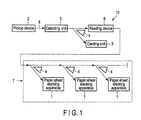
- FIG. 1 is a block diagram schematically showing an exemplary paper-sheet processing apparatus 10 including paper-sheet stacking apparatuses 1 (hereinafter referred to as stacking apparatuses 1) according to an embodiment.
- the paper-sheet processing apparatus 10 reads information, such as addresses, from a plurality of paper sheets P and then sorts and stacks the paper sheets, one after another.
- the paper-sheet processing apparatus 10 comprises a pickup device 2, a detecting unit 3, a sorting unit 4, an ejecting unit 5, a reading device 6, and a stacking unit 7.
- the stacking unit 7 has a plurality of paper-sheet stacking apparatuses 1.
- the paper sheets the paper-sheet processing apparatus 10 processes are mail items, but are not limited to mail items only.
- Paper sheets P are set in the pickup device 2, one laid on another.
- the pickup device 2 picks up the paper sheets and feeds them, one by one to a transport path 8.
- a plurality of endless transport belts (not shown) extend, two belts of each pair positioned to sandwich the transport path 8.
- the paper sheets P are transported, each held between two transport belts.
- the paper sheets P picked up onto the transport path 8 are transported, one after another, to the detecting unit 3.
- the detecting unit 3 detects any overlap of paper sheets P, short gaps between paper sheets P, and the thickness and height of each paper sheet P. Any paper sheet P irregular in dimensions is sorted out by the sorting unit 4 and transported to the ejecting unit 5.
- the other paper sheets P pass through the sorting unit 4 to the reading device 6 located downstream.
- the reading unit 6 reads information, such as an address, from each paper sheet P. From the information the reading unit 6 has read, a control unit (not shown) determines to which paper-sheet stacking apparatus 1 each paper sheet P should be sorted.
- the stacking unit 7 comprises a plurality of sorting units 4 and a plurality of paper-sheet stacking apparatuses 1. Each sorting unit 4 sorts paper sheets P in accordance with the information read by the reading unit 6.
- Each paper-sheet stacking apparatus 1 stacks the paper sheets P sorted by the sorting unit 6 associated with it. After passing through reading unit 6, the paper sheets P are sorted by the sorting units 4 in accordance with the information read from them.
- the paper sheets P sorted by any sorting unit 4 are stacked in the paper-sheet stacking apparatus 1 associated with the sorting unit 4.
- FIG. 2 and FIG. 3 are perspective views of one paper-sheet stacking apparatus 1.
- FIG. 4 is a side view of an example of the pushing mechanism incorporated in the paper-sheet stacking apparatus 1.
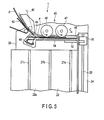
- FIG. 5 is a plan view showing a part of the paper-sheet stacking apparatus 1.
- the paper-sheet stacking apparatus 1 comprises a holding unit 20, a pushing mechanism 40, a movable backup plate (backup or stacking paddle) 54, and a variable-force spring mechanism 60.
- the holding unit 20 is configured to hold a plurality of paper sheets P in standing position.
- the pushing mechanism 40 is configured to push paper sheets P sorted into the holding unit 20, stacking them one after another in the holding unit 20.
- the backup plate 54 is opposed to the pushing mechanism 40, in the holding unit 20, and configured to hold the paper sheets P stacked, in a gap between it and the pushing mechanism 40.
- the variable-force spring mechanism 60 biases the backup plate 54 toward the pushing mechanism 40 and the stacked paper sheets P.
- the holding unit 20 has a stacking base (bottom wall) 22 and a side wall 24.
- the stacking base 22 is an almost rectangular plate on which a plurality of paper sheets P pushed by the pushing mechanism 40 are mounted in standing position, one overlapping another.
- the side wall 24 is positioned to contact the front side, either shorter or longer, of any paper sheet P transported to the holding unit 20.
- the upper surface of the stacking base 22 constitutes a support surfaced 22a that is almost horizontal.
- the side wall 24 stands almost vertical to the support surfaced 22a.
- the side wall 24 is provided, extending along one side of the support surfaced 22a in paper-sheet stacking direction D in the holding unit 20.
- an entrance base 26 having a flat surface is provided at the entrance side of the stacking base 22, an entrance base 26 having a flat surface is provided.
- the entrance base 26 is positioned one step above the stacking base 22.
- guide ribs for example three guide ribs 27a, 27b and 27c, protrude to decrease the friction between the sheet papers P stacked and the support surfaced 22a.
- Each of the guide ribs 27a, 27b and 27c extends straight from the entrance side of the support surfaced 22a to the side thereof, which is opposite in the paper-sheet stacking direction D.
- the support surfaced 22a of the stacking base 22 is positioned one step below the surface of the entrance base 26, and the upper ends of the guide ribs 27a, 27b and 27c are positioned in the same plane as the surface of the entrance base 26.
- the guide ribs 27a, 27b and 27c, which serve as support members and may contact paper sheets P, have a semicircular cross section.
- the three guide ribs 27a, 27b and 27c are arranged, one spaced apart from another in the direction orthogonal to the side wall 24. As shown in FIG. 6 , the guide rib 27a located nearer the side wall 24 than any other guide ribs and the guide rib 27a next to the guide rib 27a are positioned to support a side part of the smallest paper sheet P1 and a side part of the medium-size paper sheet P2. Further, the intermediate guide rib 27b is located away from the center C of gravity of the medium-size paper sheet P2, or more spaced apart from the side wall 24 than the center C of gravity. The guide rib 27c most spaced apart from the side wall 24 is located to support a side parts of a large paper sheet P3.
- each of the guide ribs 27a, 27b and 27c is composed of first part 25a and second part 25b.
- the first part 25a first-distance part, or initial stacking-phase part
- the second part 25b second-distance part, or intermediate stacking-phase part
- the pushing mechanism 40 comprises a plurality of transport belts 42, a transport guide 44, a pair of pushing rollers 46 and 47, a feed screw 48, and a drive motor 50 configured to drive the feed screw 48.
- the pushing mechanism 40 is provided at the entrance base 26 of the holding unit 20.
- the transport guide 44 is arranged, extending from the front side of the paper sheet P to the side wall 24, over the sheet-stacking position in the holding unit 20.
- a stopper 45 is provided at the downstream end of the transport guide 44, and is almost aligned with the side wall 24 of the holding unit 20.
- the transport belts 42 are arranged, extending along the upstream end of the transport guide 44, and are configured to pinch any paper sheet P sorted and transport the same toward a stacking position.
- the pushing rollers 46 and 47 are located adjacent, opposed to each other, at a sheet-stacking position. That is, the pushing rollers 46 and 47 are arranged, facing the backup plate 54 (later described).
- the pushing rollers 46 and 47 are arranged side by side, respectively, upstream and downstream in the direction paper sheets P are pushed. Both pushing rollers 46 and 47 are supported on the entrance base 26 and can rotate freely.
- the feed screw 48 is supported in the entrance base 26 and can rotate, and is located upstream of the pushing roller 46 in the direction paper sheets P are pushed. As shown in FIG. 6 and FIG. 7 , the feed screw 48 has a columnar shaft part 48a and a blade, or helical ridge 48b, which is formed on the outer circumferential surface of the shaft part 48a.
- the helical ridge 48b defines a screw having a pitch of 15 mm.
- the shaft part 48a has a groove 48c in one end, imparting good rotation balance to the feed screw 48.
- the drive motor 50 has its shaft coupled to the pushing roller 46, and directly drives the pushing roller 46.
- a drive belt 51 is wrapped around the pushing rollers 46 and 47, and a drive belt 52 is wrapped around the pushing roller 46 and the feed screw 48.
- the dive force of the drive motor 50 is transmitted to the pushing roller 47 and feed screw 48.
- the pushing roller 47 and feed screw 48 are thereby rotated.
- any paper sheet P that is fed, while held by the transport belts 42, is released at the entrance to the holding unit 20.
- the paper sheet P is then transported along the transport guide 44, and enters the nip between the backup plate (later described) and the pushing rollers 46 and 47.
- the paper sheet P is further fed in transport direction C, by the drive force of the pushing rollers 46 and 47 rotating in the forward direction.
- the pushing roller 47 positioned downstream rotates at a lower speed than the pushing roller 46 positioned upstream, decelerating the paper sheet P fed to the pushing roller 47.
- the paper sheet P eventually abuts, at its front side, on the stopper 45, and stops at a stacking position.
- the stopper 45 is made of a material that can absorb the impact the paper sheet P receives while transported, for example an elastic material (e.g., rubber or gel).
- the feed screw 48 has a pitch of 15 mm in this embodiment, enabling the paper-sheet stacking apparatus 1 to process a paper-sheet bundle having a thickness of 12.7 mm at most. Further, the rotation speed of the feed screw 48 can be increased, thereby to process thin paper sheets.
- the pushing mechanism 40 feeds paper sheets P, one after another, each in standing position, to the stacking position in the holding unit 20A.
- the paper sheets P are thereby continuously stacked in the direction D.
- the holding unit 20 has a backup plate (backup) 54.
- the backup plate 54 is, for example, a rectangular plate, and is opposed to the pushing rollers 46 and 47 of the pushing mechanism 40. More specifically, the backup plate 54 extends almost vertically to the support surfaced 22a of the stacking base 22 and to the side wall 24 of the holding unit 20A, and is supported to move in the paper-sheet stacking direction D. Above the side wall 24, a guide rail 28 extends parallel to the paper-sheet stacking direction D.
- the guide rail 28 supports a slider 30, which can slide along the guide rail 28.
- the slider 30 is coupled by a coupling arm to the backup plate 54.
- the backup plate 54 is therefore supported on the slider 30, and can move back and forth in the paper-sheet stacking direction D.
- the backup plate 54 is biased by the variable-force spring mechanism 60 toward the pushing rollers 46 and 47, holding the stacked paper sheets P in the gap between the pushing rollers 46 and 47. As more and more paper sheets are stacked, the backup plate 54 moves together with the slider 30 along guide rail 28, parallel to the paper-sheet stacking direction D.
- the variable-force spring mechanism 60 has a variable-force spring (Conston spring, trademark) 62 and a coupling wire 64.
- the Conston spring 62 is mounted on the side wall 24 of the holding unit 20.
- the coupling wire 64 couples the variable-force spring 61 to the slider 30.
- the variable-force spring 62 has a platelike support frame 65, a first pulley 66a, a second pulley 66b, and an elongate leaf spring 68.
- the first and second pulleys 66a and 66b are secured to the support frame 65 and can rotate.
- the leaf spring 68 is a spiral strip having a thickness, width or hardness that gradually changes from the middle part, and therefore has a spring force that gradually changes toward one end.
- a third pulley 70 is secured to the first pulley 66a and rotates together with the first pulley 66a.
- the coupling wire 64 is wound around the third pulley 70.
- the coupling wire 64 is led from the third pulley 70, passes through a through hole made in the support frame 65, is wrapped around a guide roller 74 secured to the side wall 24, and is coupled to the slider 30.
- the coupling wire 64 is led from the third pulley 70, the third pulley 70 and first pulley 66a rotate, whereby the leaf spring 68 is taken up around the first pulley 66a and fed from the second pulley 66b.
- the leaf sprint 68 generates a rewinding spring force, which is applied to the slider 30 through the coupling wire 64.
- the variable-force spring 62 applies the spring force to the slider 30 and backup plate 54, biasing the backup plate 54 toward the pushing rollers 46 and 47.
- the coupling wire 64 is further led out. The variable-force spring 62 therefore biases the backup plate 54 via the coupling wire 64.
- the backup plate 54 may move by stroke D.
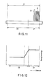
- the variable-force spring 62 biases the backup plate 54 with a first spring force (e.g., 700 g), while the backup plate 54 is moving from the initial position, i.e., the stacking position, for first distance D1 in the paper-sheet stacking direction D.
- the backup plate 54 is so moving, it is biased with a second spring force (e.g., 500 g) smaller than the first spring force.
- the variable-force spring 62 may be so designed that its force gradually decreases from the first spring force to the second spring force.
- a fill-up detecting switch 56 is provided at the rear edge of the side wall 24.
- the slider 30 slides, along with the backup plate 54, to the rear edge of the sidewall 24.
- the slider 30 turns on the pre-switch of the fill-up detecting switch 56.
- an alarm device (not shown) is activated and a lamp (not shown) blinks, attracting the operator's attention.
- the full switch of the fill-up detecting switch 56 is turned on, detecting the full state of the holding unit 20, stopping the stacking of paper sheets. Note that in the holding unit 20 of the paper-sheet stacking apparatus 1, the paper sheets P coming to the paper-sheet stacking apparatuses 1 are transported into an overflow holding unit (not shown).
- variable-force spring mechanism 60 biases the backup plate 54 toward the pushing rollers, keeping the paper sheets P in a stacked state, while accumulated in the holding unit 20.
- the spring load on the backup plate 54 is increased, preventing the backup plate 54 from being flicked by a thick or heavy paper sheet.
- the spring load on the backup plate 54 is decreased, moderating the increase in the pressure the pushing rollers 46 and 47 apply to the paper sheets P being accumulated in the holding unit 20.
- the paper-sheet stacking apparatus 1 can stack paper sheets even if the sheets are of various types.
- those parts that contact a paper sheet in the initial stacking-phase are made of a high-friction material, and those parts that contact a paper sheet in the middle stacking-phase are made of a low-friction material.
- a heavy paper sheet can be prevented from being flicked in the initial stacking-phase, and the pressure the backup plate applies to the paper sheet can be moderated from the middle stacking-phase on.
- the pushing roller 46 which is coupled directly to the drive motor 50, can be stably rotatably driven, and does not stop even if the pressure the pressure the roller 46 applies to the paper sheet P increases as more and more paper sheets accumulate in the holding unit 20.
- the invention can therefore provide a paper-sheet stacking apparatus that can stably stack paper sheets of various types.
- the invention is not limited to the embodiment described above.
- the number of sensors for detecting presence or absence of a paper sheet being transported is not limited to two. Three or more sensors may be used.
- the transparent-medium sensor and paper sheet sensor, which constitute a first sensor are not limited to reflection optical sensors and transmission optical sensors, and may be sensors of any other type.
- the time lag of the detection signal for identifying the transparent packaging medium can be set to any value, not based on the sampling cycle.
- At least one embodiment described above can provide a paper-sheet stacking apparatus that can stack paper sheets stably.
Landscapes
- Engineering & Computer Science (AREA)
- Mechanical Engineering (AREA)
- Pile Receivers (AREA)
Abstract
Description
- The embodiments described herein relate generally to paper-sheet stacking apparatuses.
- Paper-sheet stacking apparatuses are apparatuses that collect and stack, in a standing position, paper sheets such as mail items transported at high speed. Any apparatus of this type comprises a holding unit for holding paper sheets, a movable backup plate, a pushing roller and a supporting guide. The backup plate is arranged, touching the paper sheet that is an endmost sheet of the paper-sheet stack held in the holding unit. The backup plate moves in the direction the paper sheets are stacked, in accordance with the number of the paper sheets stacked, and therefore pushes the paper-sheet stack in the direction the paper sheets are stacked. The pushing roller is located at some distance from the backup plate and touches, in rolling contact, the other endmost paper sheet of the paper-sheet stack, cooperating with the backup plate to clamp the paper-sheet stack. The pushing roller receives the paper sheet next to the other endmost paper sheet, between it and the other endmost paper sheet, and then pushes the paper sheet next to the other endmost paper sheet into the end of the paper-sheet stack.
- In recent years, paper sheets (document sheets) that can be processed in the paper-sheet processing apparatus such as a mail processing apparatus have been increasing in size. Further, these paper sheets are increasing in thickness, year by year. In the paper-sheet stacking apparatus described above, the pressure applied to the backup plate is constant, and the backup member may be flicked because of the weight of the paper-sheet stack when a thick paper sheet, for example, is fed, In this case, the thick paper sheet is pushed away, and cannot be stacked. To prevent this event, the pressured applied to the backup plate may be increased. If the pressure is increased, however, the pressure for stacking paper sheets will not be mitigated. As a result, the pressure the pushing roller applies to the paper-sheet stack rises, making it difficult to feed paper sheets onto the paper-sheet stack.
- A general architecture that implements the various features of the embodiments will now be described with reference to the drawings. The drawings and the associated descriptions are provided to illustrate the embodiments and not to limit the scope of the invention.
-
FIG. 1 is a block diagram schematically showing an exemplary paper-sheet processing apparatus comprising a paper-sheet stacking apparatus according to an embodiment; -
FIG. 2 is a perspective view of an example of the paper-sheet stacking apparatus; -
FIG. 3 is a perspective view of the example of the paper-sheet stacking apparatus, as seen in a direction different from the direction in which the apparatus is viewed inFIG. 2 ; -
FIG. 4 is a side view of an example of the pushing mechanism incorporated in the paper-sheet stacking apparatus; -
FIG. 5 is a plan view showing a part of the paper-sheet stacking apparatus; -
FIG. 6 is a side view schematically showing examples of the holding unit and guide rib of the paper-sheet stacking apparatus; -
FIG. 7 is a plan view showing an example of the feeding screw incorporated in the pushing mechanism; -
FIG. 8 is a perspective view showing another example of the feeding screw; -
FIG. 9 is a side view showing the guide mechanism and variable-force spring mechanism of the paper-sheet stacking apparatus; -
FIG. 10 is a perspective view showing an example of the variable-force spring mechanism; -
FIG. 11 is a diagram showing how paper sheets are stacked in the paper-sheet stacking apparatus; and -
FIG. 12 is a graph showing an exemplary relation the number of paper sheets stacked has with the spring load (i.e., spring force) in the paper-sheet stacking apparatus. - Various embodiments will be described hereinafter with reference to the accompanying drawings.
- In general, according to one embodiment, a paper-sheet stacking apparatus includes a holding unit, a pushing mechanism, a backup, and a variable-force spring mechanism. The holding unit has a stacking base for holding a plurality of paper sheets in standing position and is configured to stack the paper sheets, one laid on another in a direction of a plane. The pushing mechanism is configured to push paper sheets transported, into the holding unit. The backup opposed to the pushing mechanism, is able to move in the direction the paper sheets are stacked and is configured to hold any paper sheet stacked between the backup and the pushing mechanism and to move away from the pushing mechanism as paper sheets are stacked one after another. The variable-force spring mechanism is configured to bias the backup toward the pushing mechanism, to apply a first spring force to the backup while the backup is moving from the pushing mechanism by a first distance in a paper-sheet stacking direction, and to apply a second spring force smaller than the first spring force to the backup while the backup is further moving by a second distance in the paper-sheet stacking direction.
-
FIG. 1 is a block diagram schematically showing an exemplary paper-sheet processing apparatus 10 including paper-sheet stacking apparatuses 1 (hereinafter referred to as stacking apparatuses 1) according to an embodiment. The paper-sheet processing apparatus 10 reads information, such as addresses, from a plurality of paper sheets P and then sorts and stacks the paper sheets, one after another. The paper-sheet processing apparatus 10 comprises apickup device 2, a detectingunit 3, asorting unit 4, anejecting unit 5, areading device 6, and astacking unit 7. Thestacking unit 7 has a plurality of paper-sheet stacking apparatuses 1. The paper sheets the paper-sheet processing apparatus 10 processes are mail items, but are not limited to mail items only. - Paper sheets P are set in the
pickup device 2, one laid on another. Thepickup device 2 picks up the paper sheets and feeds them, one by one to atransport path 8. Along thetransport path 8, a plurality of endless transport belts (not shown) extend, two belts of each pair positioned to sandwich thetransport path 8. Thus, the paper sheets P are transported, each held between two transport belts. The paper sheets P picked up onto thetransport path 8 are transported, one after another, to the detectingunit 3. The detectingunit 3 detects any overlap of paper sheets P, short gaps between paper sheets P, and the thickness and height of each paper sheet P. Any paper sheet P irregular in dimensions is sorted out by thesorting unit 4 and transported to theejecting unit 5. The other paper sheets P, i.e., sheets having regular dimensions, pass through thesorting unit 4 to thereading device 6 located downstream. Thereading unit 6 reads information, such as an address, from each paper sheet P. From the information thereading unit 6 has read, a control unit (not shown) determines to which paper-sheet stacking apparatus 1 each paper sheet P should be sorted. Thestacking unit 7 comprises a plurality ofsorting units 4 and a plurality of paper-sheet stacking apparatuses 1. Eachsorting unit 4 sorts paper sheets P in accordance with the information read by thereading unit 6. Each paper-sheet stacking apparatus 1 stacks the paper sheets P sorted by thesorting unit 6 associated with it. After passing throughreading unit 6, the paper sheets P are sorted by thesorting units 4 in accordance with the information read from them. The paper sheets P sorted by anysorting unit 4 are stacked in the paper-sheet stacking apparatus 1 associated with thesorting unit 4. - The paper-
sheet stacking apparatuses 1 will be described.FIG. 2 andFIG. 3 are perspective views of one paper-sheet stacking apparatus 1.FIG. 4 is a side view of an example of the pushing mechanism incorporated in the paper-sheet stacking apparatus 1.FIG. 5 is a plan view showing a part of the paper-sheet stacking apparatus 1. - As shown in
FIG. 2 to FIG. 5 , the paper-sheet stacking apparatus 1 comprises aholding unit 20, apushing mechanism 40, a movable backup plate (backup or stacking paddle) 54, and a variable-force spring mechanism 60. Theholding unit 20 is configured to hold a plurality of paper sheets P in standing position. Thepushing mechanism 40 is configured to push paper sheets P sorted into theholding unit 20, stacking them one after another in theholding unit 20. Thebackup plate 54 is opposed to thepushing mechanism 40, in theholding unit 20, and configured to hold the paper sheets P stacked, in a gap between it and thepushing mechanism 40. The variable-force spring mechanism 60 biases thebackup plate 54 toward thepushing mechanism 40 and the stacked paper sheets P. - The
holding unit 20 has a stacking base (bottom wall) 22 and aside wall 24. The stackingbase 22 is an almost rectangular plate on which a plurality of paper sheets P pushed by the pushingmechanism 40 are mounted in standing position, one overlapping another. Theside wall 24 is positioned to contact the front side, either shorter or longer, of any paper sheet P transported to the holdingunit 20. The upper surface of the stackingbase 22 constitutes a support surfaced 22a that is almost horizontal. Theside wall 24 stands almost vertical to the support surfaced 22a. Theside wall 24 is provided, extending along one side of the support surfaced 22a in paper-sheet stacking direction D in the holdingunit 20. At the entrance side of the stackingbase 22, anentrance base 26 having a flat surface is provided. Theentrance base 26 is positioned one step above the stackingbase 22. - From the
support surface 22a, guide ribs, for example threeguide ribs guide ribs base 22 is positioned one step below the surface of theentrance base 26, and the upper ends of theguide ribs entrance base 26. Theguide ribs - The three
guide ribs side wall 24. As shown inFIG. 6 , theguide rib 27a located nearer theside wall 24 than any other guide ribs and theguide rib 27a next to theguide rib 27a are positioned to support a side part of the smallest paper sheet P1 and a side part of the medium-size paper sheet P2. Further, theintermediate guide rib 27b is located away from the center C of gravity of the medium-size paper sheet P2, or more spaced apart from theside wall 24 than the center C of gravity. Theguide rib 27c most spaced apart from theside wall 24 is located to support a side parts of a large paper sheet P3. - As
FIG. 2 shows, each of theguide ribs first part 25a andsecond part 25b. Thefirst part 25a (first-distance part, or initial stacking-phase part) extends from the end of the pushingmechanism 40 to the middle part thereof, as viewed in the lengthwise direction of the guide rib, and is made of a high-friction material such as aluminum. Thesecond part 25b (second-distance part, or intermediate stacking-phase part) extends from thefirst part 25a to the other end of the guide rib, as viewed in the lengthwise direction of the guide rib, and is made of a material, such as Delrin, having a smaller coefficient of friction than the high-friction material. - As shown in
FIG. 2 to FIG. 5 , the pushingmechanism 40 comprises a plurality oftransport belts 42, atransport guide 44, a pair of pushingrollers feed screw 48, and adrive motor 50 configured to drive thefeed screw 48. The pushingmechanism 40 is provided at theentrance base 26 of the holdingunit 20. - The
transport guide 44 is arranged, extending from the front side of the paper sheet P to theside wall 24, over the sheet-stacking position in the holdingunit 20. Astopper 45 is provided at the downstream end of thetransport guide 44, and is almost aligned with theside wall 24 of the holdingunit 20. Thetransport belts 42 are arranged, extending along the upstream end of thetransport guide 44, and are configured to pinch any paper sheet P sorted and transport the same toward a stacking position. The pushingrollers rollers rollers rollers entrance base 26 and can rotate freely. - The
feed screw 48 is supported in theentrance base 26 and can rotate, and is located upstream of the pushingroller 46 in the direction paper sheets P are pushed. As shown inFIG. 6 and FIG. 7 , thefeed screw 48 has acolumnar shaft part 48a and a blade, orhelical ridge 48b, which is formed on the outer circumferential surface of theshaft part 48a. Thehelical ridge 48b defines a screw having a pitch of 15 mm. Theshaft part 48a has agroove 48c in one end, imparting good rotation balance to thefeed screw 48. - As
FIG. 2 to FIG. 5 show, thedrive motor 50 has its shaft coupled to the pushingroller 46, and directly drives the pushingroller 46. Adrive belt 51 is wrapped around the pushingrollers drive belt 52 is wrapped around the pushingroller 46 and thefeed screw 48. Thus, the dive force of thedrive motor 50 is transmitted to the pushingroller 47 and feedscrew 48. The pushingroller 47 and feedscrew 48 are thereby rotated. - In the pushing
mechanism 40 so configured as described above, any paper sheet P that is fed, while held by thetransport belts 42, is released at the entrance to the holdingunit 20. The paper sheet P is then transported along thetransport guide 44, and enters the nip between the backup plate (later described) and the pushingrollers rollers roller 47 positioned downstream rotates at a lower speed than the pushingroller 46 positioned upstream, decelerating the paper sheet P fed to the pushingroller 47. The paper sheet P eventually abuts, at its front side, on thestopper 45, and stops at a stacking position. Thestopper 45 is made of a material that can absorb the impact the paper sheet P receives while transported, for example an elastic material (e.g., rubber or gel). - As the paper sheet P passes over the
feed screw 48, thehelical ridge 48b of thefeed screw 48 pushes the rear side of the paper sheet P in the rotation direction of thehelical ridge 48b, namely toward the pushingroller 46, while the paper sheet P is being transported toward the pushingroller 46. This opens the entrance passage for the next paper sheet P, ultimately accomplishing continuous stacking of paper sheets. Thefeed screw 48 has a pitch of 15 mm in this embodiment, enabling the paper-sheet stacking apparatus 1 to process a paper-sheet bundle having a thickness of 12.7 mm at most. Further, the rotation speed of thefeed screw 48 can be increased, thereby to process thin paper sheets. - As specified above, the pushing
mechanism 40 feeds paper sheets P, one after another, each in standing position, to the stacking position in the holding unit 20A. In the holding unit 20A, the paper sheets P are thereby continuously stacked in the direction D. - As shown in
FIGS. 2 ,3 and5 , the holdingunit 20 has a backup plate (backup) 54. Thebackup plate 54 is, for example, a rectangular plate, and is opposed to the pushingrollers mechanism 40. More specifically, thebackup plate 54 extends almost vertically to the support surfaced 22a of the stackingbase 22 and to theside wall 24 of the holding unit 20A, and is supported to move in the paper-sheet stacking direction D. Above theside wall 24, aguide rail 28 extends parallel to the paper-sheet stacking direction D. Theguide rail 28 supports aslider 30, which can slide along theguide rail 28. Theslider 30 is coupled by a coupling arm to thebackup plate 54. Thebackup plate 54 is therefore supported on theslider 30, and can move back and forth in the paper-sheet stacking direction D. - The
backup plate 54 is biased by the variable-force spring mechanism 60 toward the pushingrollers rollers backup plate 54 moves together with theslider 30 alongguide rail 28, parallel to the paper-sheet stacking direction D. - As shown in
FIG. 2 ,FIG. 3 andFIG. 8 , the variable-force spring mechanism 60 has a variable-force spring (Conston spring, trademark) 62 and acoupling wire 64. TheConston spring 62 is mounted on theside wall 24 of the holdingunit 20. Thecoupling wire 64 couples the variable-force spring 61 to theslider 30. As shown inFIGS. 8 to 10 , the variable-force spring 62 has aplatelike support frame 65, afirst pulley 66a, asecond pulley 66b, and anelongate leaf spring 68. The first andsecond pulleys support frame 65 and can rotate. Theleaf spring 68 is a spiral strip having a thickness, width or hardness that gradually changes from the middle part, and therefore has a spring force that gradually changes toward one end. - A
third pulley 70 is secured to thefirst pulley 66a and rotates together with thefirst pulley 66a. Thecoupling wire 64 is wound around thethird pulley 70. Thecoupling wire 64 is led from thethird pulley 70, passes through a through hole made in thesupport frame 65, is wrapped around a guide roller 74 secured to theside wall 24, and is coupled to theslider 30. As thecoupling wire 64 is led from thethird pulley 70, thethird pulley 70 andfirst pulley 66a rotate, whereby theleaf spring 68 is taken up around thefirst pulley 66a and fed from thesecond pulley 66b. As a result, theleaf sprint 68 generates a rewinding spring force, which is applied to theslider 30 through thecoupling wire 64. Thus, the variable-force spring 62 applies the spring force to theslider 30 andbackup plate 54, biasing thebackup plate 54 toward the pushingrollers slider 30 and thebackup plate 54 move in the paper-sheet stacking direction D, thecoupling wire 64 is further led out. The variable-force spring 62 therefore biases thebackup plate 54 via thecoupling wire 64. - As shown in
FIG. 11 and FIG. 12 , thebackup plate 54 may move by stroke D. In this case, the variable-force spring 62 biases thebackup plate 54 with a first spring force (e.g., 700 g), while thebackup plate 54 is moving from the initial position, i.e., the stacking position, for first distance D1 in the paper-sheet stacking direction D. Thebackup plate 54 further moves for second distance D2 (= D - D1) in the paper-sheet stacking direction D, in the middle stacking-phase. While thebackup plate 54 is so moving, it is biased with a second spring force (e.g., 500 g) smaller than the first spring force. The variable-force spring 62 may be so designed that its force gradually decreases from the first spring force to the second spring force. - As shown in
FIG. 2 andFIG. 3 , a fill-up detectingswitch 56 is provided at the rear edge of theside wall 24. As more and more paper sheets P are stacked in the holdingunit 20, theslider 30 slides, along with thebackup plate 54, to the rear edge of thesidewall 24. When theslider 30 reaches a position near the fill-up position, it turns on the pre-switch of the fill-up detectingswitch 56. As a result, an alarm device (not shown) is activated and a lamp (not shown) blinks, attracting the operator's attention. When theslider 30 further moves toward the rear edge of theside wall 24, the full switch of the fill-up detectingswitch 56 is turned on, detecting the full state of the holdingunit 20, stopping the stacking of paper sheets. Note that in the holdingunit 20 of the paper-sheet stacking apparatus 1, the paper sheets P coming to the paper-sheet stacking apparatuses 1 are transported into an overflow holding unit (not shown). - In the paper-
sheet stacking apparatuses 1 configured as described above, the variable-force spring mechanism 60 biases thebackup plate 54 toward the pushing rollers, keeping the paper sheets P in a stacked state, while accumulated in the holdingunit 20. In the initial stacking-phase, the spring load on thebackup plate 54 is increased, preventing thebackup plate 54 from being flicked by a thick or heavy paper sheet. Further, from the middle stacking-phase on, the spring load on thebackup plate 54 is decreased, moderating the increase in the pressure the pushingrollers unit 20. Thus, the paper-sheet stacking apparatus 1 can stack paper sheets even if the sheets are of various types. - Moreover, of the
guide ribs base 22, those parts that contact a paper sheet in the initial stacking-phase are made of a high-friction material, and those parts that contact a paper sheet in the middle stacking-phase are made of a low-friction material. Hence, a heavy paper sheet can be prevented from being flicked in the initial stacking-phase, and the pressure the backup plate applies to the paper sheet can be moderated from the middle stacking-phase on. - Further, since the pushing
roller 46, which is coupled directly to thedrive motor 50, can be stably rotatably driven, and does not stop even if the pressure the pressure theroller 46 applies to the paper sheet P increases as more and more paper sheets accumulate in the holdingunit 20. - The invention can therefore provide a paper-sheet stacking apparatus that can stably stack paper sheets of various types.
- The invention is not limited to the embodiment described above. For example, the number of sensors for detecting presence or absence of a paper sheet being transported is not limited to two. Three or more sensors may be used. Further, the transparent-medium sensor and paper sheet sensor, which constitute a first sensor, are not limited to reflection optical sensors and transmission optical sensors, and may be sensors of any other type. The time lag of the detection signal for identifying the transparent packaging medium can be set to any value, not based on the sampling cycle.
- At least one embodiment described above can provide a paper-sheet stacking apparatus that can stack paper sheets stably.
Claims (5)
- A paper-sheet stacking apparatus comprising:a holding unit (20) having a stacking base for holding a plurality of paper sheets in standing position and configured to stack the paper sheets, one laid on another in a direction of a plane;a pushing mechanism (40) configured to push paper sheets transported, into the holding unit;a backup (54) opposed to the pushing mechanism, able to move in the direction the paper sheets are stacked and configured to hold any paper sheet stacked between the backup and the pushing mechanism and to move away from the pushing mechanism as paper sheets are stacked one after another; anda variable-force spring mechanism (60) configured to bias the backup toward the pushing mechanism, to apply a first spring force to the backup while the backup is moving from the pushing mechanism by a first distance in a paper-sheet stacking direction, and to apply a second spring force smaller than the first spring force to the backup while the backup is further moving by a second distance in the paper-sheet stacking direction.
- The paper-sheet stacking apparatus according to claim 1, wherein the holding unit has a side wall which stands on the stacking base, which extends in the paper-sheet stacking direction and on which any paper sheet abuts when pushed by the pushing mechanism; a slider is coupled to the backup and supported on the sidewall and is able to move in the paper-sheet stacking direction; and the backup is supported by the slider.
- The paper-sheet stacking apparatus according to claim 2, wherein the variable-force spring mechanism has a variable-force spring supported on the side wall and coupled to the slider.
- The paper-sheet stacking apparatus according to any one of claims 1 to 3, wherein the pushing mechanism comprises transport belts configured to transport paper sheets toward a stacking position, pushing rollers opposed to the backup at the stacking position and configured to push paper sheets toward the stacking position, and a feeding screw.
- The paper-sheet stacking apparatus according to any one of claims 1 to 4, wherein the stacking base has a flat support surface, guide ribs protruding from the support surface and configured to support a lower edge of the paper sheet, each extending straight from the pushing mechanism in the paper-sheet stacking direction; and of each guide rib, a part located with the first distance is made of a high-friction material, and a part located within the second distance is made of a low-friction material that offers less frictional resistance than the high-friction material.
Applications Claiming Priority (1)
| Application Number | Priority Date | Filing Date | Title |
|---|---|---|---|
| JP2013058807A JP6067439B2 (en) | 2013-03-21 | 2013-03-21 | Paper sheet stacking device |
Publications (2)
| Publication Number | Publication Date |
|---|---|
| EP2781479A1 true EP2781479A1 (en) | 2014-09-24 |
| EP2781479B1 EP2781479B1 (en) | 2017-12-13 |
Family
ID=50193352
Family Applications (1)
| Application Number | Title | Priority Date | Filing Date |
|---|---|---|---|
| EP14157813.8A Not-in-force EP2781479B1 (en) | 2013-03-21 | 2014-03-05 | Paper-sheet stacking apparatus |
Country Status (3)
| Country | Link |
|---|---|
| US (1) | US9272855B2 (en) |
| EP (1) | EP2781479B1 (en) |
| JP (1) | JP6067439B2 (en) |
Cited By (1)
| Publication number | Priority date | Publication date | Assignee | Title |
|---|---|---|---|---|
| CN109775403A (en) * | 2019-03-22 | 2019-05-21 | 佛山市齐志机械有限公司 | The folded machine of face tissue point |
Families Citing this family (3)
| Publication number | Priority date | Publication date | Assignee | Title |
|---|---|---|---|---|
| WO2013112150A1 (en) | 2012-01-26 | 2013-08-01 | Hewlett-Packard Development Company, L.P. | Media stacker to receive media sheets from a system |
| WO2016111013A1 (en) * | 2015-01-09 | 2016-07-14 | 富士通フロンテック株式会社 | Paper sheet accommodating device and paper sheet accommodating method |
| JP6792332B2 (en) * | 2015-12-22 | 2020-11-25 | 日本たばこ産業株式会社 | magazine |
Citations (4)
| Publication number | Priority date | Publication date | Assignee | Title |
|---|---|---|---|---|
| US3659841A (en) * | 1970-11-04 | 1972-05-02 | Ibm | Stacker for document cards |
| US5221080A (en) * | 1992-02-18 | 1993-06-22 | Bell & Howell Company | Stacker assembly having variable pressure stacker plate |
| GB2283733A (en) * | 1993-11-15 | 1995-05-17 | Pitney Bowes Inc | On edge envelope stacking apparatus |
| DE102007050185B3 (en) * | 2007-10-19 | 2009-02-26 | Siemens Ag | Stacking device for flat mail items standing on narrow side has degressive and otherwise horizontal spring characteristic of roll spring in starting region, wherein roll spring has greater width in starting region |
Family Cites Families (7)
| Publication number | Priority date | Publication date | Assignee | Title |
|---|---|---|---|---|
| US3078089A (en) * | 1961-04-05 | 1963-02-19 | Burroughs Corp | Document stacking device |
| US3452983A (en) * | 1967-09-01 | 1969-07-01 | Intern Machines Corp | Stacking device |
| US5253859A (en) * | 1991-06-07 | 1993-10-19 | Mario Ricciardi | Apparatus and method for stacking sheet-like articles |
| JP3617505B2 (en) | 2001-05-15 | 2005-02-09 | 日本電気株式会社 | Paper sheet stacking device |
| US6588743B2 (en) * | 2001-10-25 | 2003-07-08 | Pitney Bowes Inc. | Adjustable urging force system for stacker paddle |
| JP4497789B2 (en) | 2002-04-12 | 2010-07-07 | 株式会社東芝 | Paper sheet stacking device |
| DE102006030093B3 (en) * | 2006-06-28 | 2007-12-27 | Siemens Ag | Flat mail piece e.g. letter, storage module for use in postal sorting station, has storage area with splitting knife with which two forces exercised antiparallel to stacking direction of part of mail piece stored in area, respectively |
-
2013
- 2013-03-21 JP JP2013058807A patent/JP6067439B2/en not_active Expired - Fee Related
-
2014
- 2014-03-05 EP EP14157813.8A patent/EP2781479B1/en not_active Not-in-force
- 2014-03-06 US US14/198,813 patent/US9272855B2/en not_active Expired - Fee Related
Patent Citations (4)
| Publication number | Priority date | Publication date | Assignee | Title |
|---|---|---|---|---|
| US3659841A (en) * | 1970-11-04 | 1972-05-02 | Ibm | Stacker for document cards |
| US5221080A (en) * | 1992-02-18 | 1993-06-22 | Bell & Howell Company | Stacker assembly having variable pressure stacker plate |
| GB2283733A (en) * | 1993-11-15 | 1995-05-17 | Pitney Bowes Inc | On edge envelope stacking apparatus |
| DE102007050185B3 (en) * | 2007-10-19 | 2009-02-26 | Siemens Ag | Stacking device for flat mail items standing on narrow side has degressive and otherwise horizontal spring characteristic of roll spring in starting region, wherein roll spring has greater width in starting region |
Cited By (1)
| Publication number | Priority date | Publication date | Assignee | Title |
|---|---|---|---|---|
| CN109775403A (en) * | 2019-03-22 | 2019-05-21 | 佛山市齐志机械有限公司 | The folded machine of face tissue point |
Also Published As
| Publication number | Publication date |
|---|---|
| JP2014181132A (en) | 2014-09-29 |
| US9272855B2 (en) | 2016-03-01 |
| JP6067439B2 (en) | 2017-01-25 |
| US20140284873A1 (en) | 2014-09-25 |
| EP2781479B1 (en) | 2017-12-13 |
Similar Documents
| Publication | Publication Date | Title |
|---|---|---|
| EP2301869B1 (en) | Paper sheet pick up device | |
| EP2781479B1 (en) | Paper-sheet stacking apparatus | |
| JPWO2009050796A1 (en) | Paper sheet storage and feeding device | |
| JP4469671B2 (en) | Paper sheet take-out device | |
| JPH0338172B2 (en) | ||
| EP3001389B1 (en) | Banknote stacking device | |
| US20150298930A1 (en) | Paper sheet type medium stacking device | |
| US20190300311A1 (en) | Paper sheet handling apparatus and method for detecting foreign object | |
| JP4207850B2 (en) | Paper sheet handling equipment | |
| JP6676768B2 (en) | Paper sheet feeding device and foreign matter detection method | |
| JP6983303B2 (en) | Paper leaf separation device and paper leaf separation method | |
| JP2003272011A (en) | Paper sheet separation and discharge device | |
| JP2013067490A (en) | Paper sheet stacking device | |
| JPH01172175A (en) | Sheet stacking device | |
| JPS606026Y2 (en) | Paper feed device | |
| JP2918474B2 (en) | Paper processing equipment | |
| JP4461070B2 (en) | Conveyor belt correction device and paper sheet processing device | |
| JP5325695B2 (en) | Paper sheet stacking and feeding device | |
| JPH0532339A (en) | Paper processing equipment | |
| JP2804234B2 (en) | Sheet detecting device and sheet sorting device using the same | |
| JPS59191688A (en) | Magnetism detector for sheet paper | |
| JPH0532338A (en) | Paper processing equipment | |
| JPH0696311A (en) | Paper take-out device | |
| JP2019202861A (en) | Paper sheet processing equipment | |
| JP2005343576A (en) | Paper sheet handling device |
Legal Events
| Date | Code | Title | Description |
|---|---|---|---|
| PUAI | Public reference made under article 153(3) epc to a published international application that has entered the european phase |
Free format text: ORIGINAL CODE: 0009012 |
|
| 17P | Request for examination filed |
Effective date: 20140305 |
|
| AK | Designated contracting states |
Kind code of ref document: A1 Designated state(s): AL AT BE BG CH CY CZ DE DK EE ES FI FR GB GR HR HU IE IS IT LI LT LU LV MC MK MT NL NO PL PT RO RS SE SI SK SM TR |
|
| AX | Request for extension of the european patent |
Extension state: BA ME |
|
| STAA | Information on the status of an ep patent application or granted ep patent |
Free format text: STATUS: EXAMINATION IS IN PROGRESS |
|
| 17Q | First examination report despatched |
Effective date: 20161125 |
|
| GRAP | Despatch of communication of intention to grant a patent |
Free format text: ORIGINAL CODE: EPIDOSNIGR1 |
|
| STAA | Information on the status of an ep patent application or granted ep patent |
Free format text: STATUS: GRANT OF PATENT IS INTENDED |
|
| INTG | Intention to grant announced |
Effective date: 20170724 |
|
| GRAS | Grant fee paid |
Free format text: ORIGINAL CODE: EPIDOSNIGR3 |
|
| GRAA | (expected) grant |
Free format text: ORIGINAL CODE: 0009210 |
|
| STAA | Information on the status of an ep patent application or granted ep patent |
Free format text: STATUS: THE PATENT HAS BEEN GRANTED |
|
| REG | Reference to a national code |
Ref country code: GB Ref legal event code: FG4D |
|
| REG | Reference to a national code |
Ref country code: AT Ref legal event code: REF Ref document number: 954152 Country of ref document: AT Kind code of ref document: T Effective date: 20171215 Ref country code: CH Ref legal event code: EP |
|
| REG | Reference to a national code |
Ref country code: IE Ref legal event code: FG4D |
|
| REG | Reference to a national code |
Ref country code: DE Ref legal event code: R096 Ref document number: 602014018375 Country of ref document: DE |
|
| REG | Reference to a national code |
Ref country code: FR Ref legal event code: PLFP Year of fee payment: 5 |
|
| REG | Reference to a national code |
Ref country code: NL Ref legal event code: MP Effective date: 20171213 |
|
| PG25 | Lapsed in a contracting state [announced via postgrant information from national office to epo] |
Ref country code: SE Free format text: LAPSE BECAUSE OF FAILURE TO SUBMIT A TRANSLATION OF THE DESCRIPTION OR TO PAY THE FEE WITHIN THE PRESCRIBED TIME-LIMIT Effective date: 20171213 Ref country code: NO Free format text: LAPSE BECAUSE OF FAILURE TO SUBMIT A TRANSLATION OF THE DESCRIPTION OR TO PAY THE FEE WITHIN THE PRESCRIBED TIME-LIMIT Effective date: 20180313 Ref country code: FI Free format text: LAPSE BECAUSE OF FAILURE TO SUBMIT A TRANSLATION OF THE DESCRIPTION OR TO PAY THE FEE WITHIN THE PRESCRIBED TIME-LIMIT Effective date: 20171213 |
|
| REG | Reference to a national code |
Ref country code: AT Ref legal event code: MK05 Ref document number: 954152 Country of ref document: AT Kind code of ref document: T Effective date: 20171213 |
|
| PG25 | Lapsed in a contracting state [announced via postgrant information from national office to epo] |
Ref country code: LV Free format text: LAPSE BECAUSE OF FAILURE TO SUBMIT A TRANSLATION OF THE DESCRIPTION OR TO PAY THE FEE WITHIN THE PRESCRIBED TIME-LIMIT Effective date: 20171213 Ref country code: HR Free format text: LAPSE BECAUSE OF FAILURE TO SUBMIT A TRANSLATION OF THE DESCRIPTION OR TO PAY THE FEE WITHIN THE PRESCRIBED TIME-LIMIT Effective date: 20171213 Ref country code: BG Free format text: LAPSE BECAUSE OF FAILURE TO SUBMIT A TRANSLATION OF THE DESCRIPTION OR TO PAY THE FEE WITHIN THE PRESCRIBED TIME-LIMIT Effective date: 20180313 Ref country code: GR Free format text: LAPSE BECAUSE OF FAILURE TO SUBMIT A TRANSLATION OF THE DESCRIPTION OR TO PAY THE FEE WITHIN THE PRESCRIBED TIME-LIMIT Effective date: 20180314 Ref country code: RS Free format text: LAPSE BECAUSE OF FAILURE TO SUBMIT A TRANSLATION OF THE DESCRIPTION OR TO PAY THE FEE WITHIN THE PRESCRIBED TIME-LIMIT Effective date: 20171213 |
|
| PG25 | Lapsed in a contracting state [announced via postgrant information from national office to epo] |
Ref country code: NL Free format text: LAPSE BECAUSE OF FAILURE TO SUBMIT A TRANSLATION OF THE DESCRIPTION OR TO PAY THE FEE WITHIN THE PRESCRIBED TIME-LIMIT Effective date: 20171213 |
|
| PG25 | Lapsed in a contracting state [announced via postgrant information from national office to epo] |
Ref country code: SK Free format text: LAPSE BECAUSE OF FAILURE TO SUBMIT A TRANSLATION OF THE DESCRIPTION OR TO PAY THE FEE WITHIN THE PRESCRIBED TIME-LIMIT Effective date: 20171213 Ref country code: CY Free format text: LAPSE BECAUSE OF FAILURE TO SUBMIT A TRANSLATION OF THE DESCRIPTION OR TO PAY THE FEE WITHIN THE PRESCRIBED TIME-LIMIT Effective date: 20171213 Ref country code: EE Free format text: LAPSE BECAUSE OF FAILURE TO SUBMIT A TRANSLATION OF THE DESCRIPTION OR TO PAY THE FEE WITHIN THE PRESCRIBED TIME-LIMIT Effective date: 20171213 Ref country code: CZ Free format text: LAPSE BECAUSE OF FAILURE TO SUBMIT A TRANSLATION OF THE DESCRIPTION OR TO PAY THE FEE WITHIN THE PRESCRIBED TIME-LIMIT Effective date: 20171213 Ref country code: ES Free format text: LAPSE BECAUSE OF FAILURE TO SUBMIT A TRANSLATION OF THE DESCRIPTION OR TO PAY THE FEE WITHIN THE PRESCRIBED TIME-LIMIT Effective date: 20171213 |
|
| PG25 | Lapsed in a contracting state [announced via postgrant information from national office to epo] |
Ref country code: SM Free format text: LAPSE BECAUSE OF FAILURE TO SUBMIT A TRANSLATION OF THE DESCRIPTION OR TO PAY THE FEE WITHIN THE PRESCRIBED TIME-LIMIT Effective date: 20171213 Ref country code: PL Free format text: LAPSE BECAUSE OF FAILURE TO SUBMIT A TRANSLATION OF THE DESCRIPTION OR TO PAY THE FEE WITHIN THE PRESCRIBED TIME-LIMIT Effective date: 20171213 Ref country code: IT Free format text: LAPSE BECAUSE OF FAILURE TO SUBMIT A TRANSLATION OF THE DESCRIPTION OR TO PAY THE FEE WITHIN THE PRESCRIBED TIME-LIMIT Effective date: 20171213 Ref country code: AT Free format text: LAPSE BECAUSE OF FAILURE TO SUBMIT A TRANSLATION OF THE DESCRIPTION OR TO PAY THE FEE WITHIN THE PRESCRIBED TIME-LIMIT Effective date: 20171213 Ref country code: RO Free format text: LAPSE BECAUSE OF FAILURE TO SUBMIT A TRANSLATION OF THE DESCRIPTION OR TO PAY THE FEE WITHIN THE PRESCRIBED TIME-LIMIT Effective date: 20171213 Ref country code: IS Free format text: LAPSE BECAUSE OF FAILURE TO SUBMIT A TRANSLATION OF THE DESCRIPTION OR TO PAY THE FEE WITHIN THE PRESCRIBED TIME-LIMIT Effective date: 20180413 |
|
| REG | Reference to a national code |
Ref country code: DE Ref legal event code: R097 Ref document number: 602014018375 Country of ref document: DE |
|
| PLBE | No opposition filed within time limit |
Free format text: ORIGINAL CODE: 0009261 |
|
| STAA | Information on the status of an ep patent application or granted ep patent |
Free format text: STATUS: NO OPPOSITION FILED WITHIN TIME LIMIT |
|
| REG | Reference to a national code |
Ref country code: CH Ref legal event code: PL |
|
| 26N | No opposition filed |
Effective date: 20180914 |
|
| GBPC | Gb: european patent ceased through non-payment of renewal fee |
Effective date: 20180313 |
|
| PG25 | Lapsed in a contracting state [announced via postgrant information from national office to epo] |
Ref country code: DK Free format text: LAPSE BECAUSE OF FAILURE TO SUBMIT A TRANSLATION OF THE DESCRIPTION OR TO PAY THE FEE WITHIN THE PRESCRIBED TIME-LIMIT Effective date: 20171213 Ref country code: MC Free format text: LAPSE BECAUSE OF FAILURE TO SUBMIT A TRANSLATION OF THE DESCRIPTION OR TO PAY THE FEE WITHIN THE PRESCRIBED TIME-LIMIT Effective date: 20171213 |
|
| REG | Reference to a national code |
Ref country code: BE Ref legal event code: MM Effective date: 20180331 |
|
| REG | Reference to a national code |
Ref country code: IE Ref legal event code: MM4A |
|
| PG25 | Lapsed in a contracting state [announced via postgrant information from national office to epo] |
Ref country code: LU Free format text: LAPSE BECAUSE OF NON-PAYMENT OF DUE FEES Effective date: 20180305 |
|
| PG25 | Lapsed in a contracting state [announced via postgrant information from national office to epo] |
Ref country code: IE Free format text: LAPSE BECAUSE OF NON-PAYMENT OF DUE FEES Effective date: 20180305 |
|
| PG25 | Lapsed in a contracting state [announced via postgrant information from national office to epo] |
Ref country code: LI Free format text: LAPSE BECAUSE OF NON-PAYMENT OF DUE FEES Effective date: 20180331 Ref country code: CH Free format text: LAPSE BECAUSE OF NON-PAYMENT OF DUE FEES Effective date: 20180331 Ref country code: SI Free format text: LAPSE BECAUSE OF FAILURE TO SUBMIT A TRANSLATION OF THE DESCRIPTION OR TO PAY THE FEE WITHIN THE PRESCRIBED TIME-LIMIT Effective date: 20171213 Ref country code: GB Free format text: LAPSE BECAUSE OF NON-PAYMENT OF DUE FEES Effective date: 20180313 Ref country code: BE Free format text: LAPSE BECAUSE OF NON-PAYMENT OF DUE FEES Effective date: 20180331 |
|
| PG25 | Lapsed in a contracting state [announced via postgrant information from national office to epo] |
Ref country code: MT Free format text: LAPSE BECAUSE OF NON-PAYMENT OF DUE FEES Effective date: 20180305 |
|
| PG25 | Lapsed in a contracting state [announced via postgrant information from national office to epo] |
Ref country code: TR Free format text: LAPSE BECAUSE OF FAILURE TO SUBMIT A TRANSLATION OF THE DESCRIPTION OR TO PAY THE FEE WITHIN THE PRESCRIBED TIME-LIMIT Effective date: 20171213 |
|
| PG25 | Lapsed in a contracting state [announced via postgrant information from national office to epo] |
Ref country code: HU Free format text: LAPSE BECAUSE OF FAILURE TO SUBMIT A TRANSLATION OF THE DESCRIPTION OR TO PAY THE FEE WITHIN THE PRESCRIBED TIME-LIMIT; INVALID AB INITIO Effective date: 20140305 Ref country code: PT Free format text: LAPSE BECAUSE OF FAILURE TO SUBMIT A TRANSLATION OF THE DESCRIPTION OR TO PAY THE FEE WITHIN THE PRESCRIBED TIME-LIMIT Effective date: 20171213 |
|
| PG25 | Lapsed in a contracting state [announced via postgrant information from national office to epo] |
Ref country code: MK Free format text: LAPSE BECAUSE OF NON-PAYMENT OF DUE FEES Effective date: 20171213 Ref country code: LT Free format text: LAPSE BECAUSE OF FAILURE TO SUBMIT A TRANSLATION OF THE DESCRIPTION OR TO PAY THE FEE WITHIN THE PRESCRIBED TIME-LIMIT Effective date: 20171213 |
|
| PG25 | Lapsed in a contracting state [announced via postgrant information from national office to epo] |
Ref country code: AL Free format text: LAPSE BECAUSE OF FAILURE TO SUBMIT A TRANSLATION OF THE DESCRIPTION OR TO PAY THE FEE WITHIN THE PRESCRIBED TIME-LIMIT Effective date: 20171213 |
|
| PGFP | Annual fee paid to national office [announced via postgrant information from national office to epo] |
Ref country code: FR Payment date: 20230110 Year of fee payment: 10 |
|
| PGFP | Annual fee paid to national office [announced via postgrant information from national office to epo] |
Ref country code: DE Payment date: 20230110 Year of fee payment: 10 |
|
| REG | Reference to a national code |
Ref country code: DE Ref legal event code: R119 Ref document number: 602014018375 Country of ref document: DE |
|
| PG25 | Lapsed in a contracting state [announced via postgrant information from national office to epo] |
Ref country code: DE Free format text: LAPSE BECAUSE OF NON-PAYMENT OF DUE FEES Effective date: 20241001 |
|
| PG25 | Lapsed in a contracting state [announced via postgrant information from national office to epo] |
Ref country code: FR Free format text: LAPSE BECAUSE OF NON-PAYMENT OF DUE FEES Effective date: 20240331 |
|
| PG25 | Lapsed in a contracting state [announced via postgrant information from national office to epo] |
Ref country code: FR Free format text: LAPSE BECAUSE OF NON-PAYMENT OF DUE FEES Effective date: 20240331 Ref country code: DE Free format text: LAPSE BECAUSE OF NON-PAYMENT OF DUE FEES Effective date: 20241001 |