EP2781319A1 - Tondeuse corporelle - Google Patents
Tondeuse corporelle Download PDFInfo
- Publication number
- EP2781319A1 EP2781319A1 EP14158728.7A EP14158728A EP2781319A1 EP 2781319 A1 EP2781319 A1 EP 2781319A1 EP 14158728 A EP14158728 A EP 14158728A EP 2781319 A1 EP2781319 A1 EP 2781319A1
- Authority
- EP
- European Patent Office
- Prior art keywords
- comb
- mower according
- housing
- adjusting means
- movement
- Prior art date
- Legal status (The legal status is an assumption and is not a legal conclusion. Google has not performed a legal analysis and makes no representation as to the accuracy of the status listed.)
- Granted
Links
Images



Classifications
-
- B—PERFORMING OPERATIONS; TRANSPORTING
- B26—HAND CUTTING TOOLS; CUTTING; SEVERING
- B26B—HAND-HELD CUTTING TOOLS NOT OTHERWISE PROVIDED FOR
- B26B19/00—Clippers or shavers operating with a plurality of cutting edges, e.g. hair clippers, dry shavers
- B26B19/20—Clippers or shavers operating with a plurality of cutting edges, e.g. hair clippers, dry shavers with provision for shearing hair of preselected or variable length
-
- B—PERFORMING OPERATIONS; TRANSPORTING
- B26—HAND CUTTING TOOLS; CUTTING; SEVERING
- B26B—HAND-HELD CUTTING TOOLS NOT OTHERWISE PROVIDED FOR
- B26B19/00—Clippers or shavers operating with a plurality of cutting edges, e.g. hair clippers, dry shavers
- B26B19/38—Details of, or accessories for, hair clippers, or dry shavers, e.g. housings, casings, grips, guards
- B26B19/44—Suction means for collecting severed hairs or for the skin to be shaved
Definitions
- the present invention relates to the technical field of hand-held body mowers used for mowing hair or beards. More particularly, the invention relates to mowers equipped with a means of defining the length of cut, often presented in the form of a comb provided as an accessory.
- a comb designed to define several cutting lengths by a movement on the mower and this controlled by a setting means, for example a rotary knob.
- a setting means for example a rotary knob.
- a hair clipper comprising an elongated body incorporating a cutting block and a removable comb and adjustable by a movement relative to the housing.
- the comb is associated with a rotating ring arranged in the middle of the housing and comprises inside the helical grooves cooperating with a counterpart projecting from the comb, the rotation of the ring being transmitted in a translational movement of the comb.
- the object of the present invention is to overcome the aforementioned disadvantages and to propose a new mower more reliable and more compact even when combined with other motorized systems.
- Another object of the invention is to provide a comb adjusting means having a simpler construction while maintaining reliability and accuracy.
- the invention relates to a body mower comprising a housing defining a hollow body enclosing a cutting block to the front end of the housing consisting of a fixed blade and a mobile blade drivable oscillation; an electric motor comprising an output shaft for driving said movable blade; at least one comb; rotary adjusting means connected to the comb by transmission means. Said rotary adjustment means is arranged at the rear end of the housing.
- the adjusting means is preferably a knob or a ring, the adjusting means being rotatable relative to the axis of symmetry of the housing. Because the adjustment means is offset at the end of the mower which is a less user-stressed area when the device is in operation, the risk of unwanted adjustment is decreased.
- said transmission means comprise at least one longitudinal lever connected to the comb by fixing means.
- the geometric shape of the lever can be adapted according to the other components and their arrangement in the housing.
- said longitudinal lever is arranged at the periphery of said hollow body. This makes it possible to integrate other functions in the central part of the housing.
- the body mower comprises a suction system comprising at least one suction mouth communicating with a reservoir, said reservoir being arranged in series with a turbine for generating a vacuum.
- said turbine is intended to be actuated by said output shaft. This increases the suction efficiency.
- said reservoir has at least partially a substantially circular section and a U-shaped clearance for accommodating said output shaft.
- said rotary adjustment means is coupled with an endless screw by means of at least one toothed wheel, and the endless screw is coupled with said longitudinal lever so that a rotational movement of said means rotary adjustment is converted into a displacement movement by translation of said comb.
- said rotary adjustment means is coupled with said longitudinal lever by a helical connection so that a movement of rotation of said adjusting means is converted into a displacement movement by translation of said comb.
- said fixing means form a reversible attachment. This makes it possible to detach the comb from the mower and possibly to mount another of different size.
- said body mower comprises at least two combs interchangeable between them.
- a body mower as illustrated in figure 1 and designated as a whole by the reference 1 comprises a housing 10, 10 'defining a hollow body 11, 11'.
- the mower comprises at the front end E1 of the housing a cutting block 20 comprising a fixed blade 21 and a movable blade 22 intended to move back and forth relative to the fixed blade 21.
- the oscillation of the movable blade 22 is made by an electric motor 30, the motor 30 comprising an output shaft (not shown) equipped with drive means (not shown) of the movable blade.
- the clipper is equipped with a removable comb 7 on the casing 10, 10 ', the movement of the comb 7 relative to the cutting block being actuated by means of rotary adjustment 8 which is, in the illustrated example, a button 8 mounted on the axis ⁇ of symmetry of the mower.
- rotary adjustment 8 which is, in the illustrated example, a button 8 mounted on the axis ⁇ of symmetry of the mower.
- the rotary movement of the knob 8 around the same axis ⁇ is converted into a translational movement of the comb 7 by mechanical transmission means (T).
- the clipper Before presenting said transmission means (T), as visible in FIG. figure 2 , the clipper comprises in its hollow body 11, 11 'a suction system 40 cut hair.
- This suction system 40 firstly comprises a turbine 43 intended to generate a depression in the hollow body. Said turbine 43 is in fluid communication with a reservoir 42 and a suction mouth 41. The cut hair is thus sucked by the suction mouth 41 and then stored in said reservoir 42. There may be filtering means between the reservoir 42 and the turbine 43 to prevent the hair from entering the turbine 43.
- the turbine 43 and said movable blade 22 are driven by the same motor 30 which comprises on its output shaft coupling means to the turbine 43 and the drive means of the movable blade 22.
- the tank 42 such illustrated in detail in Figures 5 and 6 has a substantially circular section to maximize storage capacity.
- the front view at the figure 6 shows that the tank 42 has a U-shaped inner shape in which is housed the motor shaft 30.
- the suction system 40 has at least in the front part of the hollow body a significant amount of space.
- the adjustment knob 8 arranged at the rear end E2 of the mower 1 allows a compact internal layout with a suction system more efficient.
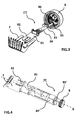
- knob 8 setting and its transmission means include a longitudinal lever 81 which is substantially parallel to the axis ⁇ of the mower. Said longitudinal lever 81 is connected to the comb 7 by fastening means 82, for example a clip. Thus, the comb 7 is mounted on the lever 81 detachably. In the case where several combs are provided to define different ranges of cutting lengths, the combs are interchangeable with each other on the lever 81.
- the transmission means (T) further comprises an intermediate support 84 mounted together to the lever 81 and coupled with a worm 83 which is itself rotated by a pinion 85, said pinion 85 and the worm 83 being coaxial.
- the pinion 85 meshes with a gear wheel 86 arranged inside the button 8 in order to recover the rotational movement thereof.
- the rotation of the pinion 85 is then transmitted in a linear displacement of the intermediate support 84 which at the same time moves the comb 7 in the same direction.
- said lever 81 is connected to a cradle 84 'arranged at the periphery of the hollow body.
- the cradle 84 ' comprises at the rear end E2 grooves cooperating with against forms on a cylinder 83' of the axis ⁇ to form a helical connection, said cylinder 83 'being rotatably connected with the button 8.
- the rotation of the button 8 is transmitted in a linear movement of the cradle 84 'which moves at the same time the lever 81 and the comb 7 in the same direction.
- the button 8 with a diameter of about 22 mm and a length of about 31.5 mm comprises a number of helices between 10 and 15, so that when the user makes a 1/2 turn, the comb is made to take a step of 4 mm in length, the comb being able to travel a race of 15mm in total.
- the button 8 includes means of notch indication to inform the user in its setting.
Landscapes
- Life Sciences & Earth Sciences (AREA)
- Forests & Forestry (AREA)
- Engineering & Computer Science (AREA)
- Mechanical Engineering (AREA)
- Harvester Elements (AREA)
- Dry Shavers And Clippers (AREA)
Abstract
- un bloc de coupe (20) à l'extrémité avant (E1) du boîtier (10) composé d'une lame fixe (21) et d'une lame mobile (22) entrainable en oscillation ;
- un moteur (30) électrique comprenant un arbre de sortie destiné à actionner ladite lame mobile(22) ;
- au moins un peigne (7)
- un moyen de réglage rotatif (8) relié au peigne (7) par des moyens de transmission (T). Ledit moyen de réglage rotatif (8) est aménagé à l'extrémité arrière (E2) du boîtier (10).
Description
- La présente invention concerne le domaine technique des tondeuses corporelles à main utilisées pour la tonte des cheveux ou des barbes. Plus particulièrement, l'invention concerne des tondeuses équipées d'un moyen de définition de la longueur de coupe, souvent présenté sous forme d'un peigne fourni en accessoire.
- Dans ce domaine, il est connu un peigne destiné à définir plusieurs longueurs de coupe par un déplacement sur la tondeuse et ceci commandé par un moyen de réglage, par exemple un bouton rotatif. Il est connu entre autres d'un brevet
EP325326 - Une telle tondeuse donne pleinement satisfaction en ce qui concerne la précision de réglage du peigne. Cependant, la bague rotative étant agencée à la périphérie du boîtier et occupant une zone voisine à celle du bloc de coupe pour rester près du peigne, un déréglage intempestif peut se produire lorsque l'appareil est en fonctionnement. De plus, cet agencement rend l'appareil très encombrant et d'autant plus quand une fonction d'aspiration est incorporée dans le boîtier.
- Le but de la présente invention est de remédier aux inconvénients susmentionnés et de proposer une nouvelle tondeuse plus fiable et plus compacte même en cas de combinaison avec d'autres systèmes motorisés.
- Un autre but de l'invention est de fournir un moyen de réglage du peigne ayant une construction plus simple tout en gardant la fiabilité et la précision.
- Afin d'atteindre ces objectifs, l'invention concerne une tondeuse corporelle comprenant un boîtier définissant un corps creux renfermant un bloc de coupe à l'extrémité avant du boîtier composé d'une lame fixe et d'une lame mobile entrainable en oscillation ; un moteur électrique comprenant un arbre de sortie destiné à actionner ladite lame mobile ; au moins un peigne ; un moyen de réglage rotatif relié au peigne par des moyens de transmission. Ledit moyen de réglage rotatif est aménagé à l'extrémité arrière du boîtier.
- Le moyen de réglage est préférablement un bouton ou une bague, le moyen de réglage étant rotatif par rapport à l'axe de symétrie du boîtier. Du fait que le moyen de réglage est déporté à l'extrémité de la tondeuse qui est une zone moins sollicitée par l'utilisateur quand l'appareil est en fonctionnement, le risque de déréglage non souhaité est diminué.
- Avantageusement, lesdits moyens de transmission comprennent au moins un levier longitudinal relié au peigne par des moyens de fixation. La forme géométrique du levier peut être adaptée en fonction des autres composants et leur agencement dans le boîtier.
- De surcroît, ledit levier longitudinal est aménagé à la périphérie dudit corps creux. Ceci permet d'intégrer d'autres fonctions dans la partie centrale du boîtier.
- Avantageusement, la tondeuse corporelle comprend un système d'aspiration comprenant au moins une bouche d'aspiration communiquant avec un réservoir, ledit réservoir étant agencé en série avec une turbine destinée à générer une dépression.
- Selon une variante, ladite turbine est destinée à être actionnée par ledit arbre de sortie. Ceci permet d'augmenter l'efficacité d'aspiration.
- Avantageusement, ledit réservoir présente au moins partiellement une section substantiellement circulaire et un dégagement en forme de U destiné à loger ledit arbre de sortie.
- Selon une première alternative, ledit moyen de réglage rotatif est couplé avec une vis sans fin par le biais d'au moins une roue dentée, et la vis sans fin est couplée avec ledit levier longitudinal de telle sorte qu'un mouvement de rotation dudit moyen de réglage rotatif est converti en un mouvement de déplacement par translation dudit peigne.
- Selon une deuxième alternative, ledit moyen de réglage rotatif est couplé avec ledit levier longitudinal par une liaison hélicoïdale de telle sorte qu'un mouvement de rotation dudit moyen de réglage est converti en un mouvement de déplacement par translation dudit peigne. Cette structure implique moins de pièces mobiles, elle est donc plus économique et plus fiable.
- De surcroît, lesdits moyens de fixation forment une fixation réversible. Ceci permet de détacher le peigne de la tondeuse et éventuellement d'en monter un autre de taille différente.
- Ainsi, ladite tondeuse corporelle comprend au moins deux peignes interchangeables entre eux.
- L'invention sera mieux comprise à l'étude des modes de réalisation pris à titre nullement limitatifs et illustrés dans les figures annexées dans lesquelles :
- La
figure 1 est une vue de la tondeuse avec son peigne démonté ; - La
figure 2 est une vue de coté de la tondeuse partiellement éclatée ; - La
figure 3 est une vue en perspective de la première alternative des moyens de transmission ; - La
figure 4 est une vue en perspective de la deuxième alternative des moyens de transmission ; - Les
figures 5 et 6 montrent une forme précise du réservoir. - Une tondeuse corporelle telle qu'illustrée à la
figure 1 et désignée dans son ensemble par la référence 1 comprend un boîtier 10, 10' définissant un corps creux 11, 11'. La tondeuse comprend à l'extrémité avant E1 du boîtier un bloc de coupe 20 comprenant une lame fixe 21 et une lame mobile 22 destinée à effectuer un mouvement de va-et-vient par rapport à la lame fixe 21. L'oscillation de la lame mobile 22 est réalisée par un moteur 30 électrique, le moteur 30 comprenant un arbre de sortie (non illustré) équipé des moyens d'entrainement (non illustrés) de la lame mobile. Afin de pouvoir définir une longueur de coupe des cheveux ou de barbe précise, la tondeuse est équipée d'un peigne 7 amovible sur le boîtier 10, 10', le mouvement du peigne 7 par rapport au bloc de coupe étant actionné par un moyen de réglage rotatif 8 qui est, dans l'exemple illustré, un bouton 8 monté sur l'axe Δ de symétrie de la tondeuse. Le mouvement rotatif du bouton 8 autour du même axe Δ est transformé en un mouvement en translation du peigne 7 par des moyens de transmission (T) mécanique. - Avant de présenter lesdits moyens de transmission (T), tel que visible à la
figure 2 , la tondeuse comprend dans son corps creux 11, 11' un système d'aspiration 40 des cheveux coupés. Ce système d'aspiration 40 comprend tout d'abord une turbine 43 destinée à générer une dépression dans le corps creux. Ladite turbine 43 est en communication de fluide avec un réservoir 42 et une bouche d'aspiration 41. Les cheveux coupés sont donc aspirés par la bouche d'aspiration 41 et ensuite stockés dans ledit réservoir 42. Il peut y avoir des moyens de filtrage entre le réservoir 42 et la turbine 43 afin d'empêcher les cheveux d'entrer dans la turbine 43. - Dans un mode de réalisation amélioré comme illustré toujours à la
figure 2 , la turbine 43 et ladite lame mobile 22 sont entraînées par le même moteur 30 qui comprend sur son arbre de sortie des moyens d'accouplement à la turbine 43 et les moyens d'entrainement de la lame mobile 22. Ainsi, le réservoir 42 tel qu'illustré en détail auxfigures 5 et 6 présente une section substantiellement circulaire permettant de maximiser la capacité de stockage. La vue de devant à lafigure 6 montre que le réservoir 42 présente une forme intérieure en U dans laquelle est logé l'arbre du moteur 30. - Cet agencement en série avec un ordre spécifique (réservoir puis turbine puis moteur) permet d'optimiser l'efficacité d'aspiration et l'utilisation de la tondeuse. Par conséquent, le système d'aspiration 40 présente au moins dans la partie avant du corps creux un encombrement assez important. Le bouton 8 de réglage agencé à l'extrémité arrière E2 de la tondeuse 1 permet un aménagement interne compact avec un système d'aspiration plus performant.
- Maintenant, on va expliquer la construction du bouton 8 de réglage ainsi que ses moyens de transmission (T). Ces derniers comprennent un levier longitudinal 81 qui est sensiblement parallèle à l'axe Δ de la tondeuse. Ledit levier longitudinal 81 est relié au peigne 7 par des moyens de fixation 82, par exemple un clip. Ainsi, le peigne 7 est monté sur le levier 81 de façon détachable. Dans le cas où plusieurs peignes sont prévus pour définir différentes gammes de longueurs de coupe, les peignes sont interchangeables entre eux sur le levier 81.
- Selon une première alternative, telle qu'illustrée à la
figure 3 , les moyens de transmission (T) comprennent en outre un support intermédiaire 84 monté solidaire au levier 81 et couplé avec une vis sans fin 83 qui est elle-même actionnée en rotation par un pignon 85, ledit pignon 85 et la vis sans fin 83 étant coaxiaux. Le pignon 85 s'engrène avec une roue dentée 86 agencée à l'intérieur du bouton 8 afin de récupérer le mouvement en rotation de celui-ci. La rotation du pignon 85 est donc ensuite transmise en un déplacement linéaire du support intermédiaire 84 qui déplace en même temps le peigne 7 dans la même direction. - Selon une deuxième alternative, telle qu'illustrée à la
figure 4 , ledit levier 81 est relié à un berceau 84' aménagé à la périphérie du corps creux. Le berceau 84' comprend à l'extrémité arrière E2 des rainures coopérant avec des contre formes sur un cylindre 83' de l'axe Δ pour former une liaison hélicoïdale, ledit cylindre 83' étant lié en rotation avec le bouton 8. Ainsi, la rotation du bouton 8 est transmise en un déplacement linéaire du berceau 84' qui déplace en même temps le levier 81 et le peigne 7 dans la même direction. Selon le mode de réalisation illustré, le bouton 8 d'un diamètre d'environ 22 mm et d'une longueur d'environ 31,5 mm comprend un nombre d'hélices compris entre 10 et 15, ce qui fait que quand l'utilisateur fait un 1/2 tour, le peigne est amené à faire un pas de 4 mm en longueur, le peigne étant capable de parcourir une course de 15mm au total. Le bouton 8 comprend des moyens d'indication en crans afin d'informer l'utilisateur dans son réglage. Bien entendu, d'autres modifications peuvent être apportées à l'invention dans le cadre des revendications annexées.
Claims (8)
- Tondeuse corporelle comprenant un boîtier (10) définissant un corps creux (11) renfermant- un bloc de coupe (20) à l'extrémité avant (E1) du boîtier (10) composé d'une lame fixe (21) et d'une lame mobile (22) entrainable en oscillation ;- un moteur (30) électrique comprenant un arbre de sortie destiné à actionner ladite lame mobile(22) ;- au moins un peigne (7) ;- un moyen de réglage rotatif (8) relié au peigne (7) par des moyens de transmission (T),ledit moyen de réglage rotatif (8) étant aménagé à l'extrémité arrière (E2) du boîtier (10),
caractérisée en ce que lesdits moyens de transmission (T) comprennent au moins un levier longitudinal (81) relié au peigne (7) par des moyens de fixation (82) et en ce que ledit levier longitudinal (81) est aménagé à la périphérie dudit corps creux (11). - Tondeuse corporelle selon la revendication 1, caractérisée en ce qu'elle comprend un système d'aspiration (40) comprenant au moins une bouche d'aspiration (41) communiquant avec un réservoir (42), ledit réservoir (42) étant agencé en série avec une turbine (43) destinée à générer une dépression.
- Tondeuse corporelle selon la revendication précédente, caractérisée en ce que ladite turbine (43) est destinée à être actionnée par ledit arbre de sortie.
- Tondeuse corporelle selon la revendication précédente, caractérisée en ce que ledit réservoir (42) présente au moins partiellement une section substantiellement circulaire et un dégagement en forme de U destiné à loger ledit arbre de sortie.
- Tondeuse corporelle selon une des revendications 1 à 4, caractérisée en ce que ledit moyen de réglage rotatif (8) est couplé avec une vis sans fin (83) par le biais d'au moins une roue dentée (86), et la vis sans fin (83) est couplée avec ledit levier longitudinal (81) de telle sorte qu'un mouvement de rotation dudit moyen de réglage rotatif (8) est converti en un mouvement de déplacement par translation dudit peigne (7).
- Tondeuse corporelle selon une des revendications 1 à 4, caractérisée en ce que ledit moyen de réglage rotatif (8) est couplé avec ledit levier longitudinal (81) par une liaison hélicoïdale de telle sorte qu'un mouvement de rotation dudit moyen de réglage (8) est converti en un mouvement de déplacement par translation dudit peigne (7).
- Tondeuse corporelle selon une des revendications précédentes, caractérisée en ce que lesdits moyens de fixation (82) forment une fixation réversible.
- Tondeuse corporelle selon la revendication précédente, caractérisée en ce qu'elle comprend au moins deux peignes interchangeables entre eux.
Applications Claiming Priority (1)
| Application Number | Priority Date | Filing Date | Title |
|---|---|---|---|
| FR1352616A FR3003499B1 (fr) | 2013-03-22 | 2013-03-22 | Tondeuse corporelle |
Publications (2)
| Publication Number | Publication Date |
|---|---|
| EP2781319A1 true EP2781319A1 (fr) | 2014-09-24 |
| EP2781319B1 EP2781319B1 (fr) | 2016-11-02 |
Family
ID=48225075
Family Applications (1)
| Application Number | Title | Priority Date | Filing Date |
|---|---|---|---|
| EP14158728.7A Active EP2781319B1 (fr) | 2013-03-22 | 2014-03-11 | Tondeuse corporelle |
Country Status (3)
| Country | Link |
|---|---|
| EP (1) | EP2781319B1 (fr) |
| CN (1) | CN203805014U (fr) |
| FR (1) | FR3003499B1 (fr) |
Cited By (2)
| Publication number | Priority date | Publication date | Assignee | Title |
|---|---|---|---|---|
| CN104985613A (zh) * | 2015-07-08 | 2015-10-21 | 宁波嘉美电器有限公司 | 一种电推剪 |
| EP4011571A4 (fr) * | 2020-10-31 | 2022-11-16 | Beijing Xiaomi Mobile Software Co., Ltd. | Structure de réglage de peigne de tondeuse à cheveux |
Citations (6)
| Publication number | Priority date | Publication date | Assignee | Title |
|---|---|---|---|---|
| US4845852A (en) * | 1987-10-23 | 1989-07-11 | Andis Company | Hair trimmer with adjustable comb |
| EP0325326A1 (fr) | 1988-01-21 | 1989-07-26 | Koninklijke Philips Electronics N.V. | Tondeuse |
| DE19612552C1 (de) * | 1996-03-29 | 1997-02-27 | Rudolf Bauer | Haarschneidegerät |
| US20050246902A1 (en) * | 2004-03-18 | 2005-11-10 | Epilady 2000, L.L.C. | Rotary extendable hair clipper |
| WO2006134576A2 (fr) * | 2005-06-17 | 2006-12-21 | Koninklijke Philips Electronics N.V. | Dispositif de coupe-cheveux presentant un moyen indicateur de longueur des cheveux |
| EP2145740A1 (fr) * | 2008-07-15 | 2010-01-20 | Braun Gmbh | Condensateur électrique |
-
2013
- 2013-03-22 FR FR1352616A patent/FR3003499B1/fr not_active Expired - Fee Related
-
2014
- 2014-03-11 CN CN201420107366.4U patent/CN203805014U/zh not_active Expired - Lifetime
- 2014-03-11 EP EP14158728.7A patent/EP2781319B1/fr active Active
Patent Citations (6)
| Publication number | Priority date | Publication date | Assignee | Title |
|---|---|---|---|---|
| US4845852A (en) * | 1987-10-23 | 1989-07-11 | Andis Company | Hair trimmer with adjustable comb |
| EP0325326A1 (fr) | 1988-01-21 | 1989-07-26 | Koninklijke Philips Electronics N.V. | Tondeuse |
| DE19612552C1 (de) * | 1996-03-29 | 1997-02-27 | Rudolf Bauer | Haarschneidegerät |
| US20050246902A1 (en) * | 2004-03-18 | 2005-11-10 | Epilady 2000, L.L.C. | Rotary extendable hair clipper |
| WO2006134576A2 (fr) * | 2005-06-17 | 2006-12-21 | Koninklijke Philips Electronics N.V. | Dispositif de coupe-cheveux presentant un moyen indicateur de longueur des cheveux |
| EP2145740A1 (fr) * | 2008-07-15 | 2010-01-20 | Braun Gmbh | Condensateur électrique |
Cited By (2)
| Publication number | Priority date | Publication date | Assignee | Title |
|---|---|---|---|---|
| CN104985613A (zh) * | 2015-07-08 | 2015-10-21 | 宁波嘉美电器有限公司 | 一种电推剪 |
| EP4011571A4 (fr) * | 2020-10-31 | 2022-11-16 | Beijing Xiaomi Mobile Software Co., Ltd. | Structure de réglage de peigne de tondeuse à cheveux |
Also Published As
| Publication number | Publication date |
|---|---|
| FR3003499A1 (fr) | 2014-09-26 |
| EP2781319B1 (fr) | 2016-11-02 |
| CN203805014U (zh) | 2014-09-03 |
| FR3003499B1 (fr) | 2015-08-07 |
Similar Documents
| Publication | Publication Date | Title |
|---|---|---|
| EP2610039B1 (fr) | Tondeuse avec molette rétractable | |
| FR2946492A3 (fr) | Coupe-herbe | |
| EP3326768B1 (fr) | Couteau électrique | |
| EP2766153B1 (fr) | Tondeuse a barbe de precision | |
| EP2781319B1 (fr) | Tondeuse corporelle | |
| FR3005442A1 (fr) | Dispositif de fixation d'essuie-glace et systeme d'essuyage comprenant ledit dispositif de fixation | |
| FR3047873A3 (fr) | Faucheuse a bras pourvue d'un moteur a combustion interne avec dispositif de demarrage ameliore | |
| CA3042195A1 (fr) | Dispositif de verrouillage a verrou rotatif a commande impulsionnelle | |
| EP2676777B1 (fr) | Tondeuse électrique avec nouvelle fixation d'une tête de coupe | |
| FR2903929A1 (fr) | Tondeuse a cheveux a reglage assiste de la hauteur de coupe | |
| WO2011131909A1 (fr) | Appareil motorise portatif pour le travail du sol | |
| FR3010254A1 (fr) | Actionneur lineaire a architecture en ligne | |
| EP2781321B1 (fr) | Tondeuse aspirante monomoteur | |
| FR3072435B1 (fr) | Boitier de transmission et engin roulant equipe d'un tel boitier | |
| EP1782709B1 (fr) | Appareil à épiler comportant un dispositif de coupe des poils | |
| EP2781320B1 (fr) | Tondeuse aspirante à ouverture souple | |
| CA2368034C (fr) | Unite de taraudage | |
| EP2570863A1 (fr) | Ensemble barillet d'horlogerie à diamètre de bonde réduit | |
| EP2785230B1 (fr) | Accessoire de preparation d'aliments presentant une configuration de rangement | |
| FR2548442A1 (fr) | Pneumo-contact pour la commande de l'alimentation electrique d'une ampoule eclairant un faisceau de fibres optiques | |
| EP1899117B1 (fr) | Appareil de type rasoir, tondeuse, epilateur et/ou "exfoliateur", à plusieurs têtes amovibles | |
| EP2436282B1 (fr) | Epilateur à cout reduit | |
| FR2673084A1 (fr) | Appareil a epiler a organe d'epilation rotatif. | |
| FR2885101A1 (fr) | Essuie-glace de type pantographe dote d'un balai d'essuyage a angle d'attaque variable | |
| FR2765471A1 (fr) | Instrument a main destine a l'abrasion des couches de cornees plantaires et talonnieres |
Legal Events
| Date | Code | Title | Description |
|---|---|---|---|
| PUAI | Public reference made under article 153(3) epc to a published international application that has entered the european phase |
Free format text: ORIGINAL CODE: 0009012 |
|
| 17P | Request for examination filed |
Effective date: 20140311 |
|
| AK | Designated contracting states |
Kind code of ref document: A1 Designated state(s): AL AT BE BG CH CY CZ DE DK EE ES FI FR GB GR HR HU IE IS IT LI LT LU LV MC MK MT NL NO PL PT RO RS SE SI SK SM TR |
|
| AX | Request for extension of the european patent |
Extension state: BA ME |
|
| R17P | Request for examination filed (corrected) |
Effective date: 20150323 |
|
| RBV | Designated contracting states (corrected) |
Designated state(s): AL AT BE BG CH CY CZ DE DK EE ES FI FR GB GR HR HU IE IS IT LI LT LU LV MC MK MT NL NO PL PT RO RS SE SI SK SM TR |
|
| GRAP | Despatch of communication of intention to grant a patent |
Free format text: ORIGINAL CODE: EPIDOSNIGR1 |
|
| INTG | Intention to grant announced |
Effective date: 20160525 |
|
| GRAS | Grant fee paid |
Free format text: ORIGINAL CODE: EPIDOSNIGR3 |
|
| GRAA | (expected) grant |
Free format text: ORIGINAL CODE: 0009210 |
|
| RAP1 | Party data changed (applicant data changed or rights of an application transferred) |
Owner name: SEB S.A. |
|
| AK | Designated contracting states |
Kind code of ref document: B1 Designated state(s): AL AT BE BG CH CY CZ DE DK EE ES FI FR GB GR HR HU IE IS IT LI LT LU LV MC MK MT NL NO PL PT RO RS SE SI SK SM TR |
|
| REG | Reference to a national code |
Ref country code: GB Ref legal event code: FG4D Free format text: NOT ENGLISH |
|
| REG | Reference to a national code |
Ref country code: AT Ref legal event code: REF Ref document number: 841358 Country of ref document: AT Kind code of ref document: T Effective date: 20161115 Ref country code: CH Ref legal event code: EP |
|
| REG | Reference to a national code |
Ref country code: IE Ref legal event code: FG4D Free format text: LANGUAGE OF EP DOCUMENT: FRENCH |
|
| REG | Reference to a national code |
Ref country code: DE Ref legal event code: R096 Ref document number: 602014004537 Country of ref document: DE |
|
| REG | Reference to a national code |
Ref country code: NL Ref legal event code: FP |
|
| PG25 | Lapsed in a contracting state [announced via postgrant information from national office to epo] |
Ref country code: LV Free format text: LAPSE BECAUSE OF FAILURE TO SUBMIT A TRANSLATION OF THE DESCRIPTION OR TO PAY THE FEE WITHIN THE PRESCRIBED TIME-LIMIT Effective date: 20161102 |
|
| REG | Reference to a national code |
Ref country code: LT Ref legal event code: MG4D |
|
| REG | Reference to a national code |
Ref country code: AT Ref legal event code: MK05 Ref document number: 841358 Country of ref document: AT Kind code of ref document: T Effective date: 20161102 |
|
| REG | Reference to a national code |
Ref country code: FR Ref legal event code: PLFP Year of fee payment: 4 |
|
| PG25 | Lapsed in a contracting state [announced via postgrant information from national office to epo] |
Ref country code: GR Free format text: LAPSE BECAUSE OF FAILURE TO SUBMIT A TRANSLATION OF THE DESCRIPTION OR TO PAY THE FEE WITHIN THE PRESCRIBED TIME-LIMIT Effective date: 20170203 Ref country code: SE Free format text: LAPSE BECAUSE OF FAILURE TO SUBMIT A TRANSLATION OF THE DESCRIPTION OR TO PAY THE FEE WITHIN THE PRESCRIBED TIME-LIMIT Effective date: 20161102 Ref country code: NO Free format text: LAPSE BECAUSE OF FAILURE TO SUBMIT A TRANSLATION OF THE DESCRIPTION OR TO PAY THE FEE WITHIN THE PRESCRIBED TIME-LIMIT Effective date: 20170202 Ref country code: LT Free format text: LAPSE BECAUSE OF FAILURE TO SUBMIT A TRANSLATION OF THE DESCRIPTION OR TO PAY THE FEE WITHIN THE PRESCRIBED TIME-LIMIT Effective date: 20161102 |
|
| PG25 | Lapsed in a contracting state [announced via postgrant information from national office to epo] |
Ref country code: PL Free format text: LAPSE BECAUSE OF FAILURE TO SUBMIT A TRANSLATION OF THE DESCRIPTION OR TO PAY THE FEE WITHIN THE PRESCRIBED TIME-LIMIT Effective date: 20161102 Ref country code: ES Free format text: LAPSE BECAUSE OF FAILURE TO SUBMIT A TRANSLATION OF THE DESCRIPTION OR TO PAY THE FEE WITHIN THE PRESCRIBED TIME-LIMIT Effective date: 20161102 Ref country code: AT Free format text: LAPSE BECAUSE OF FAILURE TO SUBMIT A TRANSLATION OF THE DESCRIPTION OR TO PAY THE FEE WITHIN THE PRESCRIBED TIME-LIMIT Effective date: 20161102 Ref country code: IS Free format text: LAPSE BECAUSE OF FAILURE TO SUBMIT A TRANSLATION OF THE DESCRIPTION OR TO PAY THE FEE WITHIN THE PRESCRIBED TIME-LIMIT Effective date: 20170302 Ref country code: RS Free format text: LAPSE BECAUSE OF FAILURE TO SUBMIT A TRANSLATION OF THE DESCRIPTION OR TO PAY THE FEE WITHIN THE PRESCRIBED TIME-LIMIT Effective date: 20161102 Ref country code: FI Free format text: LAPSE BECAUSE OF FAILURE TO SUBMIT A TRANSLATION OF THE DESCRIPTION OR TO PAY THE FEE WITHIN THE PRESCRIBED TIME-LIMIT Effective date: 20161102 Ref country code: PT Free format text: LAPSE BECAUSE OF FAILURE TO SUBMIT A TRANSLATION OF THE DESCRIPTION OR TO PAY THE FEE WITHIN THE PRESCRIBED TIME-LIMIT Effective date: 20170302 Ref country code: HR Free format text: LAPSE BECAUSE OF FAILURE TO SUBMIT A TRANSLATION OF THE DESCRIPTION OR TO PAY THE FEE WITHIN THE PRESCRIBED TIME-LIMIT Effective date: 20161102 |
|
| PG25 | Lapsed in a contracting state [announced via postgrant information from national office to epo] |
Ref country code: CZ Free format text: LAPSE BECAUSE OF FAILURE TO SUBMIT A TRANSLATION OF THE DESCRIPTION OR TO PAY THE FEE WITHIN THE PRESCRIBED TIME-LIMIT Effective date: 20161102 Ref country code: SK Free format text: LAPSE BECAUSE OF FAILURE TO SUBMIT A TRANSLATION OF THE DESCRIPTION OR TO PAY THE FEE WITHIN THE PRESCRIBED TIME-LIMIT Effective date: 20161102 Ref country code: EE Free format text: LAPSE BECAUSE OF FAILURE TO SUBMIT A TRANSLATION OF THE DESCRIPTION OR TO PAY THE FEE WITHIN THE PRESCRIBED TIME-LIMIT Effective date: 20161102 Ref country code: DK Free format text: LAPSE BECAUSE OF FAILURE TO SUBMIT A TRANSLATION OF THE DESCRIPTION OR TO PAY THE FEE WITHIN THE PRESCRIBED TIME-LIMIT Effective date: 20161102 Ref country code: RO Free format text: LAPSE BECAUSE OF FAILURE TO SUBMIT A TRANSLATION OF THE DESCRIPTION OR TO PAY THE FEE WITHIN THE PRESCRIBED TIME-LIMIT Effective date: 20161102 |
|
| REG | Reference to a national code |
Ref country code: DE Ref legal event code: R097 Ref document number: 602014004537 Country of ref document: DE |
|
| PG25 | Lapsed in a contracting state [announced via postgrant information from national office to epo] |
Ref country code: IT Free format text: LAPSE BECAUSE OF FAILURE TO SUBMIT A TRANSLATION OF THE DESCRIPTION OR TO PAY THE FEE WITHIN THE PRESCRIBED TIME-LIMIT Effective date: 20161102 Ref country code: BG Free format text: LAPSE BECAUSE OF FAILURE TO SUBMIT A TRANSLATION OF THE DESCRIPTION OR TO PAY THE FEE WITHIN THE PRESCRIBED TIME-LIMIT Effective date: 20170202 Ref country code: SM Free format text: LAPSE BECAUSE OF FAILURE TO SUBMIT A TRANSLATION OF THE DESCRIPTION OR TO PAY THE FEE WITHIN THE PRESCRIBED TIME-LIMIT Effective date: 20161102 |
|
| PLBE | No opposition filed within time limit |
Free format text: ORIGINAL CODE: 0009261 |
|
| STAA | Information on the status of an ep patent application or granted ep patent |
Free format text: STATUS: NO OPPOSITION FILED WITHIN TIME LIMIT |
|
| 26N | No opposition filed |
Effective date: 20170803 |
|
| REG | Reference to a national code |
Ref country code: CH Ref legal event code: PL |
|
| PG25 | Lapsed in a contracting state [announced via postgrant information from national office to epo] |
Ref country code: MC Free format text: LAPSE BECAUSE OF FAILURE TO SUBMIT A TRANSLATION OF THE DESCRIPTION OR TO PAY THE FEE WITHIN THE PRESCRIBED TIME-LIMIT Effective date: 20161102 Ref country code: SI Free format text: LAPSE BECAUSE OF FAILURE TO SUBMIT A TRANSLATION OF THE DESCRIPTION OR TO PAY THE FEE WITHIN THE PRESCRIBED TIME-LIMIT Effective date: 20161102 |
|
| REG | Reference to a national code |
Ref country code: IE Ref legal event code: MM4A |
|
| PG25 | Lapsed in a contracting state [announced via postgrant information from national office to epo] |
Ref country code: LU Free format text: LAPSE BECAUSE OF NON-PAYMENT OF DUE FEES Effective date: 20170311 |
|
| PG25 | Lapsed in a contracting state [announced via postgrant information from national office to epo] |
Ref country code: IE Free format text: LAPSE BECAUSE OF NON-PAYMENT OF DUE FEES Effective date: 20170311 Ref country code: CH Free format text: LAPSE BECAUSE OF NON-PAYMENT OF DUE FEES Effective date: 20170331 Ref country code: LI Free format text: LAPSE BECAUSE OF NON-PAYMENT OF DUE FEES Effective date: 20170331 |
|
| REG | Reference to a national code |
Ref country code: BE Ref legal event code: MM Effective date: 20170331 |
|
| REG | Reference to a national code |
Ref country code: FR Ref legal event code: PLFP Year of fee payment: 5 |
|
| PG25 | Lapsed in a contracting state [announced via postgrant information from national office to epo] |
Ref country code: BE Free format text: LAPSE BECAUSE OF NON-PAYMENT OF DUE FEES Effective date: 20170331 |
|
| PG25 | Lapsed in a contracting state [announced via postgrant information from national office to epo] |
Ref country code: MT Free format text: LAPSE BECAUSE OF FAILURE TO SUBMIT A TRANSLATION OF THE DESCRIPTION OR TO PAY THE FEE WITHIN THE PRESCRIBED TIME-LIMIT Effective date: 20161102 |
|
| GBPC | Gb: european patent ceased through non-payment of renewal fee |
Effective date: 20180311 |
|
| PG25 | Lapsed in a contracting state [announced via postgrant information from national office to epo] |
Ref country code: GB Free format text: LAPSE BECAUSE OF NON-PAYMENT OF DUE FEES Effective date: 20180311 |
|
| PG25 | Lapsed in a contracting state [announced via postgrant information from national office to epo] |
Ref country code: HU Free format text: LAPSE BECAUSE OF FAILURE TO SUBMIT A TRANSLATION OF THE DESCRIPTION OR TO PAY THE FEE WITHIN THE PRESCRIBED TIME-LIMIT; INVALID AB INITIO Effective date: 20140311 |
|
| PG25 | Lapsed in a contracting state [announced via postgrant information from national office to epo] |
Ref country code: CY Free format text: LAPSE BECAUSE OF NON-PAYMENT OF DUE FEES Effective date: 20161102 |
|
| PG25 | Lapsed in a contracting state [announced via postgrant information from national office to epo] |
Ref country code: MK Free format text: LAPSE BECAUSE OF FAILURE TO SUBMIT A TRANSLATION OF THE DESCRIPTION OR TO PAY THE FEE WITHIN THE PRESCRIBED TIME-LIMIT Effective date: 20161102 |
|
| PG25 | Lapsed in a contracting state [announced via postgrant information from national office to epo] |
Ref country code: TR Free format text: LAPSE BECAUSE OF FAILURE TO SUBMIT A TRANSLATION OF THE DESCRIPTION OR TO PAY THE FEE WITHIN THE PRESCRIBED TIME-LIMIT Effective date: 20161102 |
|
| PGFP | Annual fee paid to national office [announced via postgrant information from national office to epo] |
Ref country code: NL Payment date: 20200227 Year of fee payment: 7 Ref country code: DE Payment date: 20200311 Year of fee payment: 7 |
|
| PG25 | Lapsed in a contracting state [announced via postgrant information from national office to epo] |
Ref country code: AL Free format text: LAPSE BECAUSE OF FAILURE TO SUBMIT A TRANSLATION OF THE DESCRIPTION OR TO PAY THE FEE WITHIN THE PRESCRIBED TIME-LIMIT Effective date: 20161102 |
|
| REG | Reference to a national code |
Ref country code: DE Ref legal event code: R119 Ref document number: 602014004537 Country of ref document: DE |
|
| REG | Reference to a national code |
Ref country code: NL Ref legal event code: MM Effective date: 20210401 |
|
| PG25 | Lapsed in a contracting state [announced via postgrant information from national office to epo] |
Ref country code: DE Free format text: LAPSE BECAUSE OF NON-PAYMENT OF DUE FEES Effective date: 20211001 Ref country code: NL Free format text: LAPSE BECAUSE OF NON-PAYMENT OF DUE FEES Effective date: 20210401 |
|
| P01 | Opt-out of the competence of the unified patent court (upc) registered |
Effective date: 20230517 |
|
| PGFP | Annual fee paid to national office [announced via postgrant information from national office to epo] |
Ref country code: FR Payment date: 20260330 Year of fee payment: 13 |