EP2781298A2 - Workpiece assembly system and method for assembling workpiece - Google Patents
Workpiece assembly system and method for assembling workpiece Download PDFInfo
- Publication number
- EP2781298A2 EP2781298A2 EP20140159042 EP14159042A EP2781298A2 EP 2781298 A2 EP2781298 A2 EP 2781298A2 EP 20140159042 EP20140159042 EP 20140159042 EP 14159042 A EP14159042 A EP 14159042A EP 2781298 A2 EP2781298 A2 EP 2781298A2
- Authority
- EP
- European Patent Office
- Prior art keywords
- station
- robot
- pallet
- assembly system
- surface plate
- Prior art date
- Legal status (The legal status is an assumption and is not a legal conclusion. Google has not performed a legal analysis and makes no representation as to the accuracy of the status listed.)
- Withdrawn
Links
Images



Classifications
-
- B—PERFORMING OPERATIONS; TRANSPORTING
- B23—MACHINE TOOLS; METAL-WORKING NOT OTHERWISE PROVIDED FOR
- B23P—METAL-WORKING NOT OTHERWISE PROVIDED FOR; COMBINED OPERATIONS; UNIVERSAL MACHINE TOOLS
- B23P21/00—Machines for assembling a multiplicity of different parts to compose units, with or without preceding or subsequent working of such parts, e.g. with program control
- B23P21/004—Machines for assembling a multiplicity of different parts to compose units, with or without preceding or subsequent working of such parts, e.g. with program control the units passing two or more work-stations whilst being composed
-
- Y—GENERAL TAGGING OF NEW TECHNOLOGICAL DEVELOPMENTS; GENERAL TAGGING OF CROSS-SECTIONAL TECHNOLOGIES SPANNING OVER SEVERAL SECTIONS OF THE IPC; TECHNICAL SUBJECTS COVERED BY FORMER USPC CROSS-REFERENCE ART COLLECTIONS [XRACs] AND DIGESTS
- Y10—TECHNICAL SUBJECTS COVERED BY FORMER USPC
- Y10T—TECHNICAL SUBJECTS COVERED BY FORMER US CLASSIFICATION
- Y10T29/00—Metal working
- Y10T29/49—Method of mechanical manufacture
- Y10T29/49826—Assembling or joining
- Y10T29/49828—Progressively advancing of work assembly station or assembled portion of work
- Y10T29/49829—Advancing work to successive stations [i.e., assembly line]
-
- Y—GENERAL TAGGING OF NEW TECHNOLOGICAL DEVELOPMENTS; GENERAL TAGGING OF CROSS-SECTIONAL TECHNOLOGIES SPANNING OVER SEVERAL SECTIONS OF THE IPC; TECHNICAL SUBJECTS COVERED BY FORMER USPC CROSS-REFERENCE ART COLLECTIONS [XRACs] AND DIGESTS
- Y10—TECHNICAL SUBJECTS COVERED BY FORMER USPC
- Y10T—TECHNICAL SUBJECTS COVERED BY FORMER US CLASSIFICATION
- Y10T29/00—Metal working
- Y10T29/53—Means to assemble or disassemble
- Y10T29/534—Multiple station assembly or disassembly apparatus
- Y10T29/53417—Means to fasten work parts together
Definitions
- the present invention relates to a workpiece assembly system and a method for assembling a workpiece.
- Japanese Unexamined Patent Application Publication No. 2003-62727 discloses an assembly apparatus including a station for workers to provide components and a station for robots to perform assembly.
- An object of the present invention is to provide a system and a method for minimizing cycle time of workpiece assembly involving a manual operation and a robotic operation.
- a workpiece assembly system includes a first manual station in which a person performs an operation of providing a first component set onto a pallet, a first robot station in which a robot performs an operation of assembling the first component set into a workpiece on a surface plate, and a conveyor that conveys the pallet and the surface plate from the first robot station to a subsequent manual station. After the robot has removed the first component set from the pallet and before the robot finishes the operation in the first robot station, the pallet is conveyed to the subsequent manual station prior to the surface plate.
- cycle time of workpiece assembly involving a manual operation and a robotic operation can be minimized.
- a "workpiece” refers to an object completed by the assembly, for example, an industrial product or a component of the product.
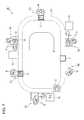
- Fig. 1 schematically illustrates a workpiece assembly system 10 according to a first embodiment of the present invention in a plan view.
- the assembly system 10 illustrated in Fig. 1 is a system for assembling an industrial robot 50 illustrated in Fig. 2 .
- the industrial robot 50 includes an S shaft, an L shaft, a U shaft, a B shaft, an R shaft, and a T shaft.
- S shaft an S shaft
- L shaft an L shaft
- U shaft a shaft
- B shaft a shaft
- R shaft an R shaft
- T shaft a case where the industrial robot 50 is assembled is described as an example, but an object completed by the assembly is not limited to the industrial robot 50.
- the assembly system 10 includes a manual station S M , a robot station S A , an annular conveyor C1, and a controller 100 that integrally controls the stations S M and S A and the conveyor C1.
- Fig. 1 illustrates a state where robots R assemble an S-shaft component set 50S into a semi-finished industrial robot 50, in which a process is finished up to S-shaft assembly, on a surface plate Q in the robot station S A .
- a worker M prepares an L-shaft component set 50L on a pallet P for the subsequent step.
- the L-shaft component set 50L includes components such as an arm, a motor, a speed reducer, and bolts. Since the process of assembling the industrial robot 50 involves a large amount of work for bolting, multiple robots R capable of bolting may be provided in the robot station S A (see Fig. 1 ).
- the pallet P carrying the component set 50S moves over the conveyor C1 in the direction of arrows illustrated in Fig. 1 and stops at a position drawn by a dot-and-dash line.
- the robots R pick up the components on the stopped pallet P and place the components on a table 15.
- the position at which the pallet P stops is preferably adjacent to the robots R and downstream from the robot station S A .
- the pallet P emptied of the components becomes no longer in the stationary state and is transported to the manual station S M again by the conveyor C1.
- annular conveyor C1 examples include a roller conveyor and a belt conveyor.
- stoppers such as pins are caused to protrude from below the conveyor C1 to stop the pallet P and the surface plate Q at predetermined positions
- the use of a roller conveyor having a gap between rollers is preferable.
- the conveyor C1 returns the pallet P to the manual station S M after the robots R have removed the S-shaft component set (first component set) 50S from the pallet P and before the robots R finish the operation in the robot station S A ( Fig. 3A ).
- the robots R pick up the component set 50S on the pallet P and place the component set 50S on the table 15.
- the pallet P emptied of the component set 50S is returned to the manual station S M . Since the pallet P is returned to the manual station S M in the course of the operation of the robots R in this manner, a worker M can start the subsequent operation without having to wait for the robots R to finish their operation.
- the worker M provides an L-shaft component set (second component set) 50L onto the returned pallet P.
- the conveyor C1 conveys the pallet P to the robot station S A ( Fig. 3B ).
- the robots R in the robot station S A finish bolting, a semi-finished workpiece W on which the S shaft has been mounted is conveyed from the robot station S A to the manual station S M while being carried on the surface plate Q.
- the component set 50L on the pallet P from the manual station S M is placed on the table 15 by the robots R ( Fig. 4A ).
- the worker M checks the state of the workpiece W from the robot station S A and then performs a manual operation (wiring, for example) that is difficult for the robots R to perform ( Fig. 4B ).
- a method for assembling a workpiece includes a step of manually providing the S-shaft component set 50S onto the pallet P in the manual station S M ; a step of assembling the component set 50S into a workpiece W on the surface plate Q using a robot R in the robot station S A ; a step of conveying the pallet P and the surface plate Q to the manual station S M using the conveyor C1 in such a manner that the pallet P precedes the surface plate Q; and a step of manually providing the L-shaft component set 50L from the robot station S A onto the pallet P in the manual station S M .
- the pallet P is returned to the manual station S M prior to the surface plate Q.
- a robot R performs multiple different operations for assembling different shafts to complete the industrial robot 50. Specifically, after the worker M repeatedly performs the operation of providing components and the wiring operation and the robots R repeatedly perform assembly an appropriate number of times, the industrial robot 50 including the S shaft, the L shaft, the U shaft, the B shaft, the R shaft, and the T shaft is completely assembled. Alternatively, a tip end portion beyond the U shaft may be separately assembled into a unit and this unit may be provided to the assembly system 10 as one part.
- the industrial robot 50 completed after rotating over the conveyor C1 a predetermined number of times is conveyed to a place for the subsequent step via a conveyor C.
- an automated guided vehicle AGV may be used for conveying the industrial robot 50 to a place for the subsequent step.
- this embodiment enables cycle time reduction.
- This embodiment also advantageously dispenses with the need for multiple lines for providing components since the components are provided at a single position (manual station S M ).
- FIG. 5A and 5B the case where the industrial robot 50 is assembled by rotating a set of the pallet P and the surface plate Q multiple times over the annular conveyor C2 is described as an example.
- two sets each including a pallet and a surface plate may be conveyed by the conveyor C2.
- An assembly system 20 illustrated in Figs. 5A and 5B includes a set of a pallet P1 and a surface plate Q1 upstream from the pallet P1 and a set of a pallet P2 and a surface plate Q2 upstream from the pallet P2.
- differences between the first embodiment and the second embodiment will be mainly described.
- a robot station S A of the assembly system 20 robots R perform assembly of an S shaft on the surface plate Q2.
- the worker M provides wiring of the S shaft on the surface plate Q1 (see Fig. 5A ).
- the conveyor C2 conveys the surface plate Q1 to a buffer B (see Fig. 5B ), in which the pallet P1 has previously been placed.
- the buffer B is disposed between the manual station S M and the robot station S A for temporarily receiving a pallet and/or a surface plate from the manual station S M while the robot station S A is unable to accept the pallet and/or the surface plate.
- Another buffer may be disposed between the robot station S A and the manual station S M .
- the conveyor C2 After the robots R have removed the S-shaft component set 50S from the pallet P2 and before the robots R finish their operation in the robot station S A , the conveyor C2 returns the pallet P2 to the manual station S M (see Fig. 5B ). Since the pallet P2 is returned to the manual station S M in the course of the operation of the robots R, the worker M can start the subsequent operation without having to wait for the robots R to finish their operation.
- the worker M provides an L-shaft component set (second component set) 50L to the returned pallet P2.
- the robots R finish the operation in the robot station S A and the surface plate Q2 is returned to the manual station S M (see Fig. 6A ).
- the pallet P2 carrying the component set 50L is dispatched from the buffer B to the robot station S A
- the surface plate Q2 is delivered from the robot station S A to the manual station S M .
- the worker M checks the assembly state of the workpiece W on the surface plate Q2 and then performs wiring on the workpiece W.
- the surface plate Q1 is delivered from the buffer B to the robot station S A (see Fig. 6B ).
- two sets of a pallet and a surface plate rotate over the conveyor C2 multiple times, so that two industrial robots 50 can be simultaneously completed.
- the assembly system 20 allows the worker M to perform the subsequent operation while the robots R are performing their operation.
- the assembly system 20 also enables simultaneous assembly of two workpieces W, further reducing cycle time.
- the assembly system 20 also advantageously dispenses with the need for multiple lines for providing components since the components are provided at a single position (manual station S M ).
- the first and second embodiments are described using the case, as an example, where a pallet or pallets and a surface plate or plates rotate between the manual station S M and the robot station S A multiple times.
- a system may be configured to assemble an industrial robot 50 after one rotation of a pallet and a surface plate over an annularly conveyor.
- manual stations S M and robot stations S A may be alternately disposed around an annular conveyor C3 to assemble an industrial robot 50 while a pallet P and a surface plate Q upstream from the pallet P rotate once over the conveyor C3.
- An assembly system 30 according to the third embodiment includes three manual stations S M (first to third manual stations) and three robot stations S A (first to third robot stations). The numbers of stations may be appropriately changed in accordance with products to be assembled.
- the assembly system 30 allows a worker M to start the subsequent operation while a robot R is performing its operation, cycle time can be further reduced.
- the assembly system 30 also advantageously enables a pallet P subjected to a final step to be returned to an initial step via the conveyor C3.
- the third embodiment is described using the annular conveyor C3 as an example, but a conveyor having an initial end and a terminal end may be used instead of an annular conveyor.
- a linear conveyor illustrated in Fig. 8 or a curved conveyor (not illustrated) may be used.
- a conveyor C4 illustrated in Fig. 8 has an initial end C4a and a terminal end C4b.
- Manual stations S M and robot stations S A are alternately arranged along the direction in which the conveyor C4 extends.
- An assembly system 40 may assemble an industrial robot 50 by bringing a pallet P and a surface plate Q upstream from the pallet P to the terminal end C4b while subjecting them to operations at the stations S M and S A .
- the assembly system 40 allows a worker M to start the subsequent operation while a robot R is performing its operation, thereby reducing cycle time.
Landscapes
- Engineering & Computer Science (AREA)
- Mechanical Engineering (AREA)
- Automatic Assembly (AREA)
- Manipulator (AREA)
Abstract
A workpiece assembly system (10, 20, 30, 40) includes a first manual station (SM) in which a person (M) performs an operation of providing a first component set (50S) onto a pallet (P); a first robot station (SA) in which a robot (R) performs an operation of assembling the first component set (50S) into a workpiece (W) on a surface plate (Q, Q1, Q2); and a conveyor (C1, C2, C3, C4) that conveys the pallet (P) and the surface plate (Q, Q1, Q2) from the first robot station (SA) to a subsequent manual station. After the robot (R) has removed the first component set (50S) from the pallet (P) and before the robot (R) finishes the operation in the first robot station (SA), the pallet (P) is conveyed to the subsequent manual station prior to the surface plate (Q, Q1, Q2).
Description
- The present invention relates to a workpiece assembly system and a method for assembling a workpiece.
- A process of assembling industrial products involves, in some cases, a manual operation and a robotic operation. Japanese Unexamined Patent Application Publication No.
2003-62727 - In an existing system for assembling workpieces, human workers often have to wait for robots to finish their operation, whereas the robots often have to wait for the human workers to finish their operation. Thus, cycle time of the assembly operation has been difficult to reduce.
- An object of the present invention is to provide a system and a method for minimizing cycle time of workpiece assembly involving a manual operation and a robotic operation.
- According to an aspect of the disclosure, a workpiece assembly system includes a first manual station in which a person performs an operation of providing a first component set onto a pallet, a first robot station in which a robot performs an operation of assembling the first component set into a workpiece on a surface plate, and a conveyor that conveys the pallet and the surface plate from the first robot station to a subsequent manual station. After the robot has removed the first component set from the pallet and before the robot finishes the operation in the first robot station, the pallet is conveyed to the subsequent manual station prior to the surface plate.
- According to the present invention, cycle time of workpiece assembly involving a manual operation and a robotic operation can be minimized.
-
-
Fig. 1 schematically illustrates a workpiece assembly system according to a first embodiment of the present invention in a plan view. -
Fig. 2 is a perspective view of an example of an industrial robot assembled by the workpiece assembly system illustrated inFig. 1 . -
Figs. 3A and 3B are plan views illustrating steps in the process of assembling a workpiece with the assembly system according to the first embodiment. -
Figs. 4A and 4B are plan views illustrating steps in the process of assembling a workpiece with the assembly system according to the first embodiment. -
Figs. 5A and 5B are plan views illustrating steps in the process of assembling a workpiece with the assembly system according to a second embodiment. -
Figs. 6A and 6B are plan views illustrating steps in the process of assembling a workpiece with the assembly system according to the second embodiment. -
Fig. 7 schematically illustrates a workpiece assembly system according to a third embodiment of the present invention in a plan view. -
Fig. 8 schematically illustrates a workpiece assembly system according to a fourth embodiment of the present invention in a plan view. - Embodiments will be described below in detail referring to the drawings. In the description, the same components or components having the same function will be denoted by the same reference symbols and the redundant description is not given. Herein, a "workpiece" refers to an object completed by the assembly, for example, an industrial product or a component of the product.
-
Fig. 1 schematically illustrates aworkpiece assembly system 10 according to a first embodiment of the present invention in a plan view. Theassembly system 10 illustrated inFig. 1 is a system for assembling anindustrial robot 50 illustrated inFig. 2 . Theindustrial robot 50 includes an S shaft, an L shaft, a U shaft, a B shaft, an R shaft, and a T shaft. Here, a case where theindustrial robot 50 is assembled is described as an example, but an object completed by the assembly is not limited to theindustrial robot 50. - The
assembly system 10 includes a manual station SM, a robot station SA, an annular conveyor C1, and acontroller 100 that integrally controls the stations SM and SA and the conveyor C1.Fig. 1 illustrates a state where robots R assemble an S-shaft component set 50S into a semi-finishedindustrial robot 50, in which a process is finished up to S-shaft assembly, on a surface plate Q in the robot station SA. Meanwhile, in the manual station SM, a worker M prepares an L-shaft component set 50L on a pallet P for the subsequent step. The L-shaft component set 50L includes components such as an arm, a motor, a speed reducer, and bolts. Since the process of assembling theindustrial robot 50 involves a large amount of work for bolting, multiple robots R capable of bolting may be provided in the robot station SA (seeFig. 1 ). - The pallet P carrying the component set 50S moves over the conveyor C1 in the direction of arrows illustrated in
Fig. 1 and stops at a position drawn by a dot-and-dash line. The robots R pick up the components on the stopped pallet P and place the components on a table 15. The position at which the pallet P stops is preferably adjacent to the robots R and downstream from the robot station SA. The pallet P emptied of the components becomes no longer in the stationary state and is transported to the manual station SM again by the conveyor C1. - Examples of the annular conveyor C1 include a roller conveyor and a belt conveyor. When the assembly involves an operation in which stoppers (not illustrated) such as pins are caused to protrude from below the conveyor C1 to stop the pallet P and the surface plate Q at predetermined positions, the use of a roller conveyor having a gap between rollers is preferable.
- Referring now to
Figs. 3A and 3B , the movement of the pallet P and the surface plate Q on which the workpiece W is assembled will be described. The conveyor C1 returns the pallet P to the manual station SM after the robots R have removed the S-shaft component set (first component set) 50S from the pallet P and before the robots R finish the operation in the robot station SA (Fig. 3A ). Specifically, the robots R pick up the component set 50S on the pallet P and place the component set 50S on the table 15. The pallet P emptied of the component set 50S is returned to the manual station SM. Since the pallet P is returned to the manual station SM in the course of the operation of the robots R in this manner, a worker M can start the subsequent operation without having to wait for the robots R to finish their operation. - The worker M provides an L-shaft component set (second component set) 50L onto the returned pallet P. As soon as the worker M finishes providing the component set 50L, the conveyor C1 conveys the pallet P to the robot station SA (
Fig. 3B ). When the robots R in the robot station SA finish bolting, a semi-finished workpiece W on which the S shaft has been mounted is conveyed from the robot station SA to the manual station SM while being carried on the surface plate Q. Meanwhile, the component set 50L on the pallet P from the manual station SM is placed on the table 15 by the robots R (Fig. 4A ). The worker M checks the state of the workpiece W from the robot station SA and then performs a manual operation (wiring, for example) that is difficult for the robots R to perform (Fig. 4B ). - A method for assembling a workpiece according to the embodiment includes a step of manually providing the S-shaft component set 50S onto the pallet P in the manual station SM; a step of assembling the component set 50S into a workpiece W on the surface plate Q using a robot R in the robot station SA; a step of conveying the pallet P and the surface plate Q to the manual station SM using the conveyor C1 in such a manner that the pallet P precedes the surface plate Q; and a step of manually providing the L-shaft component set 50L from the robot station SA onto the pallet P in the manual station SM. Specifically, in the method according to the embodiment, as illustrated in
Fig. 3A , after the robots R have removed the component set 50S from the pallet P and before the robots R finish the operation in the robot station SA, the pallet P is returned to the manual station SM prior to the surface plate Q. - In this embodiment, while a set of the pallet P and the surface plate Q rotate over the conveyor C1 multiple times, a robot R performs multiple different operations for assembling different shafts to complete the
industrial robot 50. Specifically, after the worker M repeatedly performs the operation of providing components and the wiring operation and the robots R repeatedly perform assembly an appropriate number of times, theindustrial robot 50 including the S shaft, the L shaft, the U shaft, the B shaft, the R shaft, and the T shaft is completely assembled. Alternatively, a tip end portion beyond the U shaft may be separately assembled into a unit and this unit may be provided to theassembly system 10 as one part. - The
industrial robot 50 completed after rotating over the conveyor C1 a predetermined number of times is conveyed to a place for the subsequent step via a conveyor C. Instead of the conveyor C, an automated guided vehicle (AGV) may be used for conveying theindustrial robot 50 to a place for the subsequent step. - Since the worker M can perform the subsequent operation while the robots R perform their operation, this embodiment enables cycle time reduction. This embodiment also advantageously dispenses with the need for multiple lines for providing components since the components are provided at a single position (manual station SM).
- In the first embodiment, the case where the
industrial robot 50 is assembled by rotating a set of the pallet P and the surface plate Q multiple times over the annular conveyor C2 is described as an example. However, as illustrated inFigs. 5A and 5B , two sets each including a pallet and a surface plate may be conveyed by the conveyor C2. Anassembly system 20 illustrated inFigs. 5A and 5B includes a set of a pallet P1 and a surface plate Q1 upstream from the pallet P1 and a set of a pallet P2 and a surface plate Q2 upstream from the pallet P2. Hereinbelow, differences between the first embodiment and the second embodiment will be mainly described. - In a robot station SA of the
assembly system 20, robots R perform assembly of an S shaft on the surface plate Q2. Concurrently, in the manual station SM, the worker M provides wiring of the S shaft on the surface plate Q1 (seeFig. 5A ). When the worker M finishes the wiring, the conveyor C2 conveys the surface plate Q1 to a buffer B (seeFig. 5B ), in which the pallet P1 has previously been placed. The buffer B is disposed between the manual station SM and the robot station SA for temporarily receiving a pallet and/or a surface plate from the manual station SM while the robot station SA is unable to accept the pallet and/or the surface plate. Another buffer may be disposed between the robot station SA and the manual station SM. - After the robots R have removed the S-shaft component set 50S from the pallet P2 and before the robots R finish their operation in the robot station SA, the conveyor C2 returns the pallet P2 to the manual station SM (see
Fig. 5B ). Since the pallet P2 is returned to the manual station SM in the course of the operation of the robots R, the worker M can start the subsequent operation without having to wait for the robots R to finish their operation. - The worker M provides an L-shaft component set (second component set) 50L to the returned pallet P2. When the worker M nearly finishes providing the components, the robots R finish the operation in the robot station SA and the surface plate Q2 is returned to the manual station SM (see
Fig. 6A ). Then, the pallet P2 carrying the component set 50L is dispatched from the buffer B to the robot station SA, while the surface plate Q2 is delivered from the robot station SA to the manual station SM. The worker M checks the assembly state of the workpiece W on the surface plate Q2 and then performs wiring on the workpiece W. At the time when the surface plate Q2 is dispatched from the robot station SA, the surface plate Q1 is delivered from the buffer B to the robot station SA (seeFig. 6B ). - In this embodiment, two sets of a pallet and a surface plate rotate over the conveyor C2 multiple times, so that two
industrial robots 50 can be simultaneously completed. Theassembly system 20 allows the worker M to perform the subsequent operation while the robots R are performing their operation. Theassembly system 20 also enables simultaneous assembly of two workpieces W, further reducing cycle time. Theassembly system 20 also advantageously dispenses with the need for multiple lines for providing components since the components are provided at a single position (manual station SM). - The first and second embodiments are described using the case, as an example, where a pallet or pallets and a surface plate or plates rotate between the manual station SM and the robot station SA multiple times. However, a system may be configured to assemble an
industrial robot 50 after one rotation of a pallet and a surface plate over an annularly conveyor. Specifically, as illustrated inFig. 7 , manual stations SM and robot stations SA may be alternately disposed around an annular conveyor C3 to assemble anindustrial robot 50 while a pallet P and a surface plate Q upstream from the pallet P rotate once over the conveyor C3. Anassembly system 30 according to the third embodiment includes three manual stations SM (first to third manual stations) and three robot stations SA (first to third robot stations). The numbers of stations may be appropriately changed in accordance with products to be assembled. - Since the
assembly system 30 allows a worker M to start the subsequent operation while a robot R is performing its operation, cycle time can be further reduced. Theassembly system 30 also advantageously enables a pallet P subjected to a final step to be returned to an initial step via the conveyor C3. - The third embodiment is described using the annular conveyor C3 as an example, but a conveyor having an initial end and a terminal end may be used instead of an annular conveyor. A linear conveyor illustrated in
Fig. 8 or a curved conveyor (not illustrated) may be used. - A conveyor C4 illustrated in
Fig. 8 has an initial end C4a and a terminal end C4b. Manual stations SM and robot stations SA are alternately arranged along the direction in which the conveyor C4 extends. Anassembly system 40 may assemble anindustrial robot 50 by bringing a pallet P and a surface plate Q upstream from the pallet P to the terminal end C4b while subjecting them to operations at the stations SM and SA. Theassembly system 40 allows a worker M to start the subsequent operation while a robot R is performing its operation, thereby reducing cycle time. - Although some embodiments have been described above in detail, they are not restrictive. Although a case where an
industrial robot 50 is assembled is described as an example in an embodiment, a dual-arm robot may be assembled instead of theindustrial robot 50. Alternatively, industrial products other than robots may be assembled.
Claims (13)
- A workpiece assembly system (10, 20, 30, 40), comprising:a first manual station (SM) in which a person (M) performs an operation of providing a first component set (50S) onto a pallet (P);a first robot station (SA) in which a robot (R) performs an operation of assembling the first component set (50S) into a workpiece (W) on a surface plate (Q, Q1, Q2); anda conveyor (C1, C2, C3, C4) that conveys the pallet (P) and the surface plate (Q, Q1, Q2) from the first robot station (SA) to a subsequent manual station,wherein, after the robot (R) has removed the first component set (50S) from the pallet (P) and before the robot (R) finishes the operation in the first robot station (SA), the pallet (P) is conveyed to the subsequent manual station prior to the surface plate (Q, Q1, Q2).
- The assembly system according to Claim 1, wherein the conveyor is annularly disposed and the subsequent manual station is the first manual station.
- The assembly system according to Claim 2, wherein the system concurrently assembles two sets each including the pallet and the surface plate into two workpieces.
- The assembly system according to Claim 1, wherein the conveyor has an initial end and a terminal end.
- The assembly system according to Claims 1 to 4, further comprising a second manual station serving as the subsequent manual station.
- The assembly system according to Claims 1 to 5, wherein a second component set (50L) is provided onto the pallet in the subsequent manual station.
- The assembly system according to Claim 6, further comprising a subsequent robot station in which a robot performs an operation of assembling the second component set (50L) into another workpiece on the surface plate.
- The assembly system according to Claim 7, wherein the conveyor is annularly disposed and the subsequent robot station is the first robot station.
- The assembly system according to Claims 1 to 8, further comprising a buffer (B), in which either one of the pallet and the surface plate is stored, at a portion of the conveyor.
- The assembly system according to Claims 1 to 9, wherein the operation performed in each manual station includes assembling a workpiece in addition to providing a component set onto the pallet.
- The assembly system according to Claim 10, wherein the operation performed in each manual station includes wiring.
- The assembly system according to Claims 1 to 11, wherein the operation performed in the robot station includes bolting.
- A method for assembling a workpiece, comprising:manually providing a first component set (50S) onto a pallet (P) in a first manual station (SM);assembling the first component set (50S) into a workpiece (W) on a surface plate (Q, Q1, Q2) using a robot (R) in a first robot station (SA);conveying the pallet (P) from the first manual station (SM) to the first robot station (SA) using a conveyor (C1, C2, C3, C4); andconveying the pallet (P) and the surface plate (Q, Q1, Q2) from the first robot station (SA) to a subsequent manual station using the conveyor (C1, C2, C3, C4),wherein, after the robot (R) has removed the first component set (50S) from the pallet (P) and before the robot (R) finishes the operation in the first robot station (SA), the pallet (P) is conveyed to the subsequent manual station prior to the surface plate (Q, Q1, Q2).
Applications Claiming Priority (1)
| Application Number | Priority Date | Filing Date | Title |
|---|---|---|---|
| JP2013056996A JP5741618B2 (en) | 2013-03-19 | 2013-03-19 | Workpiece assembly apparatus and assembly method |
Publications (1)
| Publication Number | Publication Date |
|---|---|
| EP2781298A2 true EP2781298A2 (en) | 2014-09-24 |
Family
ID=50276956
Family Applications (1)
| Application Number | Title | Priority Date | Filing Date |
|---|---|---|---|
| EP20140159042 Withdrawn EP2781298A2 (en) | 2013-03-19 | 2014-03-12 | Workpiece assembly system and method for assembling workpiece |
Country Status (4)
| Country | Link |
|---|---|
| US (1) | US20140283357A1 (en) |
| EP (1) | EP2781298A2 (en) |
| JP (1) | JP5741618B2 (en) |
| CN (1) | CN104057299A (en) |
Cited By (1)
| Publication number | Priority date | Publication date | Assignee | Title |
|---|---|---|---|---|
| EP3120970A1 (en) * | 2015-07-22 | 2017-01-25 | KUKA Systems GmbH | Production device |
Families Citing this family (11)
| Publication number | Priority date | Publication date | Assignee | Title |
|---|---|---|---|---|
| DE102010005314A1 (en) * | 2010-01-21 | 2010-08-19 | Daimler Ag | Device for mounting e.g. panorama glass roof, at body of e.g. electric vehicle, to transport testing system for fuel of fuel cell system, has transport device moved independent of conveyors in rail-free manner |
| US9521738B1 (en) | 2013-12-23 | 2016-12-13 | Flextronics Ap, Llc | Graphite sheet to protect SMT components from thermal exposure |
| US9789572B1 (en) * | 2014-01-09 | 2017-10-17 | Flextronics Ap, Llc | Universal automation line |
| JP6529402B2 (en) * | 2015-09-17 | 2019-06-12 | シチズン時計株式会社 | Assembly apparatus and method |
| US10220511B2 (en) * | 2016-07-28 | 2019-03-05 | X Development Llc | Customized robotic installation based on measurements collected on site |
| US20180029235A1 (en) * | 2016-07-28 | 2018-02-01 | X Development Llc | Error Accrual and Mitigation During Robotic Process |
| JP2018022645A (en) * | 2016-08-05 | 2018-02-08 | 住友電装株式会社 | Wiring module production facility |
| DE202017101643U1 (en) * | 2017-03-21 | 2018-05-08 | Kuka Systems Gmbh | manufacturing station |
| CN108557391B (en) * | 2018-05-11 | 2024-02-06 | 苏州赛腾菱欧智能科技有限公司 | Transverse locking mechanism |
| CN111689114A (en) * | 2020-07-17 | 2020-09-22 | 江苏速升自动化装备股份有限公司 | Tray system |
| EP4198173B1 (en) * | 2021-12-16 | 2026-03-25 | Abb Schweiz Ag | A method for assembling alkaline electrolyzer units of a hydrogen producing plant |
Citations (1)
| Publication number | Priority date | Publication date | Assignee | Title |
|---|---|---|---|---|
| JP2003062727A (en) | 2001-04-26 | 2003-03-05 | Fuji Photo Film Co Ltd | Assembly unit |
Family Cites Families (20)
| Publication number | Priority date | Publication date | Assignee | Title |
|---|---|---|---|---|
| GB2212468B (en) * | 1987-11-20 | 1992-06-10 | Sony Corp | Automatic assembly apparatus |
| US5105647A (en) * | 1988-06-23 | 1992-04-21 | Maher John H | System for transferring workpieces through a series of work stations |
| JPH03294127A (en) * | 1990-04-05 | 1991-12-25 | Canon Inc | Article feeding method |
| JP3037488B2 (en) * | 1991-11-22 | 2000-04-24 | マツダ株式会社 | Work assembly method |
| JPH06155197A (en) * | 1992-11-16 | 1994-06-03 | Pfu Ltd | Member feeding system for mixed flow production system |
| JP3355616B2 (en) * | 1994-04-28 | 2002-12-09 | 株式会社安川電機 | Crane steady rest control method |
| US5994864A (en) * | 1995-09-11 | 1999-11-30 | Kabushiki Kaisha Yaskawa Denki | Robot controller |
| EP0865858B1 (en) * | 1995-09-19 | 2004-02-18 | Kabushiki Kaisha Yaskawa Denki | Automatic welding condition setting device |
| US6481558B1 (en) * | 1998-12-18 | 2002-11-19 | Asyst Technologies, Inc. | Integrated load port-conveyor transfer system |
| JP2001219322A (en) * | 2000-02-04 | 2001-08-14 | Fuji Photo Film Co Ltd | Assembling device |
| JP2003039253A (en) * | 2001-07-24 | 2003-02-12 | Fuji Photo Film Co Ltd | Method for adjusting position of assembling part |
| US6889727B2 (en) * | 2003-02-21 | 2005-05-10 | Abbott Laboratories | Apparatus and method for the preparation of experiments using proteins contained within gels |
| JP4207619B2 (en) * | 2003-03-26 | 2009-01-14 | マツダ株式会社 | Assembly production system and assembly production method |
| EP1827754B1 (en) * | 2004-12-14 | 2009-03-11 | FELSOMAT GmbH & Co. KG | Work cell for assembling units of workpieces on pallets and method for operating the same |
| DE202005001780U1 (en) * | 2005-02-03 | 2006-06-08 | Kuka Schweissanlagen Gmbh | Manufacturing facility for components |
| JP2009023013A (en) * | 2007-07-17 | 2009-02-05 | Mazda Motor Corp | Assembly production line |
| JP5405235B2 (en) * | 2008-09-05 | 2014-02-05 | Ntn株式会社 | Production equipment and production system |
| JP5375297B2 (en) * | 2009-04-16 | 2013-12-25 | 株式会社安川電機 | Robot system |
| IT1397438B1 (en) * | 2009-12-30 | 2013-01-10 | Comau Spa | INSTALLATION FOR THE ASSEMBLY OF MECHANICAL PARTS ON BODIES OF MOTOR VEHICLES |
| JP5454491B2 (en) * | 2011-02-25 | 2014-03-26 | 株式会社安川電機 | Work system |
-
2013
- 2013-03-19 JP JP2013056996A patent/JP5741618B2/en not_active Expired - Fee Related
-
2014
- 2014-02-19 CN CN201410056669.2A patent/CN104057299A/en active Pending
- 2014-03-12 EP EP20140159042 patent/EP2781298A2/en not_active Withdrawn
- 2014-03-18 US US14/217,474 patent/US20140283357A1/en not_active Abandoned
Patent Citations (1)
| Publication number | Priority date | Publication date | Assignee | Title |
|---|---|---|---|---|
| JP2003062727A (en) | 2001-04-26 | 2003-03-05 | Fuji Photo Film Co Ltd | Assembly unit |
Cited By (1)
| Publication number | Priority date | Publication date | Assignee | Title |
|---|---|---|---|---|
| EP3120970A1 (en) * | 2015-07-22 | 2017-01-25 | KUKA Systems GmbH | Production device |
Also Published As
| Publication number | Publication date |
|---|---|
| JP5741618B2 (en) | 2015-07-01 |
| JP2014180729A (en) | 2014-09-29 |
| US20140283357A1 (en) | 2014-09-25 |
| CN104057299A (en) | 2014-09-24 |
Similar Documents
| Publication | Publication Date | Title |
|---|---|---|
| US20140283357A1 (en) | Workpiece assembly system and method for assembling workpiece | |
| US9027215B2 (en) | Production apparatus | |
| US20160030995A1 (en) | Uncoiling, blanking and forming method | |
| US9022716B2 (en) | Work conveying system | |
| EP2781299A2 (en) | Workpiece assembling apparatus and workpiece assembling method | |
| JPWO2006013644A1 (en) | Production system | |
| US11192164B2 (en) | Centering blanks | |
| EP2759357A1 (en) | Forging press device for valve | |
| CN106141479A (en) | A kind of body of a motor car assembly device and apply the assembling method of described device illegally assembled car vehicle body | |
| JP2014117758A (en) | Robot work system using multiple robots | |
| CN109051746B (en) | Automatic feeding and discharging system for post-processing of automobile sealing strip | |
| EP1135314B1 (en) | Conveyor system and vehicle skid | |
| US4667805A (en) | Robotic part presentation system | |
| JPH08112572A (en) | Angle iron automatic machining method and equipment | |
| CN118331203B (en) | A skylight sequential construction control method and system | |
| JPH02121719A (en) | Conveying method for rim roll forming line | |
| TW201317076A (en) | Auxiliary working device for automatic manufacture system | |
| EP4153510B1 (en) | Method for operating a technical installation, and technical installation | |
| CN219193672U (en) | Automatic production line for airing solid explosive column | |
| CN113664354B (en) | Projection welding equipment, system and method for vehicle field | |
| CN117397077A (en) | Apparatus and method for assembling a battery pack for powering an electric traction motor of an electric motor vehicle | |
| JP4207619B2 (en) | Assembly production system and assembly production method | |
| CN113458843B (en) | Machine tool with dual inlet and dual outlet and related method of use | |
| CN108463312A (en) | The assembly line of motor vehicle body component | |
| CN108837981B (en) | Spraying method of automatic door leaf spraying machine |
Legal Events
| Date | Code | Title | Description |
|---|---|---|---|
| PUAI | Public reference made under article 153(3) epc to a published international application that has entered the european phase |
Free format text: ORIGINAL CODE: 0009012 |
|
| 17P | Request for examination filed |
Effective date: 20140312 |
|
| AK | Designated contracting states |
Kind code of ref document: A2 Designated state(s): AL AT BE BG CH CY CZ DE DK EE ES FI FR GB GR HR HU IE IS IT LI LT LU LV MC MK MT NL NO PL PT RO RS SE SI SK SM TR |
|
| AX | Request for extension of the european patent |
Extension state: BA ME |
|
| STAA | Information on the status of an ep patent application or granted ep patent |
Free format text: STATUS: THE APPLICATION HAS BEEN WITHDRAWN |
|
| 18W | Application withdrawn |
Effective date: 20160725 |