EP2781149A2 - Sectional driveshaft arrangement for a corn head - Google Patents
Sectional driveshaft arrangement for a corn head Download PDFInfo
- Publication number
- EP2781149A2 EP2781149A2 EP14155752.0A EP14155752A EP2781149A2 EP 2781149 A2 EP2781149 A2 EP 2781149A2 EP 14155752 A EP14155752 A EP 14155752A EP 2781149 A2 EP2781149 A2 EP 2781149A2
- Authority
- EP
- European Patent Office
- Prior art keywords
- driveshaft
- slip clutch
- inner sleeve
- row unit
- arrangement
- Prior art date
- Legal status (The legal status is an assumption and is not a legal conclusion. Google has not performed a legal analysis and makes no representation as to the accuracy of the status listed.)
- Granted
Links
Images



Classifications
-
- A—HUMAN NECESSITIES
- A01—AGRICULTURE; FORESTRY; ANIMAL HUSBANDRY; HUNTING; TRAPPING; FISHING
- A01D—HARVESTING; MOWING
- A01D45/00—Harvesting of standing crops
- A01D45/02—Harvesting of standing crops of maize, i.e. kernel harvesting
-
- A—HUMAN NECESSITIES
- A01—AGRICULTURE; FORESTRY; ANIMAL HUSBANDRY; HUNTING; TRAPPING; FISHING
- A01D—HARVESTING; MOWING
- A01D45/00—Harvesting of standing crops
- A01D45/02—Harvesting of standing crops of maize, i.e. kernel harvesting
- A01D45/021—Cornheaders
-
- A—HUMAN NECESSITIES
- A01—AGRICULTURE; FORESTRY; ANIMAL HUSBANDRY; HUNTING; TRAPPING; FISHING
- A01D—HARVESTING; MOWING
- A01D69/00—Driving mechanisms or parts thereof for harvesters or mowers
- A01D69/06—Gearings
Definitions
- the present invention relates generally to agricultural harvesters. More particularly it relates to harvesting heads. Even more particularly it relates to driveshaft arrangements for driving row units of a corn head.
- Corn heads are agricultural implements configured to be supported on the front of a combine harvester.
- the corn head is typically arranged as a laterally extending transverse frame on which several row units are fixed.
- the row units are spaced equidistantly across the leading edge of the corn head frame.
- Row units are driven by one or more driveshafts that extend in a transverse direction parallel to the transverse extent of the corn head frame.
- all of the row units on at least one side of the corn head are driven by a common polygonal driveshaft that can be 15-20 feet long and pass through 6-8 separate row units.
- this driveshaft In order to repair the row units, this driveshaft must be removed.
- the removal process typically requires a farmer to support the corn head on agricultural harvester, unbolt a cover at the outer end of the corn head, attach a chain to the end of the corn head driveshaft, attach the other end of the chain to a tow vehicle, such as a tractor or truck, and then remove the 15-20 foot long corn head driveshaft by pulling it out of its 6-8 row units with the tow vehicle.
- This process takes an extended period of time, and typically two or more people to perform.
- the replacement process is even more time-consuming, since the long driveshaft must be inserted into the corn head and threaded through the 6-8 row units one at a time.
- Another arrangement, shown in EP 0 775 437 B2 is for a forage harvester.
- the gearboxes have internal driveshafts that are splined at each end and extend outward from either side of the gearbox.
- Another arrangement, shown in US 7,640,718 B2 shows several gearboxes for a forage harvester that have short drive shafts extending through the gearboxes and stub axles with universal joints that connect the driveshafts that extend from each gearbox.
- Another arrangement, shown in DE 103 16 003 A1 shows a parallel drive arrangement for driving row units on corn heads.
- Another arrangement, shown in US 6,349,258 B1 illustrate a drive arrangement for driving transversely adjustable row units.
- a sectional driveshaft arrangement for a corn head comprising: a first row unit comprising a first gearbox and a first slip clutch drivingly coupled to the first gearbox; a first driveshaft, the first driveshaft having a first end and a second end opposite the first end, wherein the first end terminates within the first slip clutch; and a second driveshaft, the second driveshaft having a third end and a fourth end opposite to the third end, wherein the third end terminates within the first slip clutch; wherein the first slip clutch is configured to be driven in rotation by the first driveshaft and to drive the second driveshaft in rotation.
- the sectional driveshaft arrangement for a corn head may further comprise a second row unit adjacent to the first row unit, the second row unit may comprise a second gearbox and a second slip clutch, and the fourth end of the second driveshaft may terminate within the second slip clutch, and the second slip clutch may be configured to be driven in rotation by the second driveshaft.
- the sectional driveshaft arrangement for a corn head may further comprise a third driveshaft, the third driveshaft may have a fifth end and a sixth end opposite the fifth end; and the fifth end may terminate in the second slip clutch and the second slip clutch may drive the third driveshaft in rotation.
- the sectional driveshaft arrangement for a corn head may further comprise a third row unit that is adjacent to the second row unit, and the third row unit may comprise a third gearbox and a third slip clutch, and the sixth end may terminate in the third slip clutch, and the third slip clutch may be configured to be driven in rotation by the third driveshaft.
- the first slip clutch may comprise an inner sleeve that receives and supports the first end and the third end, and the inner sleeve may be configured to transmit power from the first end to the third end.
- the inner sleeve may have a through hole with an inner surface that, in axial cross-section, defines a first polygon, and the first end and the third end may have outer surfaces that, in axial cross-section, define a second polygon, such that the second polygon may be contained within boundaries of the first polygon, and such that the second polygon is not capable of being rotated with respect to the first polygon while staying contained within boundaries of the first polygon.
- the first end may be configured to be received in a first side of the inner sleeve and to axially translate through the inner sleeve until the first end passes entirely through the inner sleeve and extends at least partially out a second side of the inner sleeve.
- the third end may be configured to be received in the second side of the inner sleeve and axially translate with respect to the inner sleeve until the third end passes entirely through the inner sleeve and extends at least partially out the first side of the inner sleeve.
- the first slip clutch may have an abutment that is disposed to prevent the first end or the third end from passing completely through the first slip clutch.
- the first slip clutch may define a first aperture extending into the first slip clutch from one side of the first slip clutch, and wherein the first slip clutch may define a second aperture extending into the first slip clutch from a side of the first slip clutch that is opposite the one side, and wherein the first end is configured to be inserted into the first aperture, and the second end is configured to be inserted into the second aperture.
- the first end has a first rotational axis and the second end has a second rotational axis, and further wherein the first rotational axis and the second rotational axis are coaxial.
- a corn head 100 comprises a frame 102, toolbar supports 104, toolbar 106, row unit 108, row unit 110, row unit 112, row unit 114, row unit 116, row unit 118, row unit 120, and row unit 122.
- Frame 102 is elongate member extending laterally, and generally perpendicular to the direction of travel "V" of the corn head 100.
- Frame 102 (and hence the corn head 100) is supported on a feederhouse 128 that extends forward from the front end of a combine harvester (not shown).
- Toolbar supports 104 are fixed to frame 102 and extend forward therefrom.
- Toolbar 106 extends laterally and parallel to frame 102. Toolbar 106 extends substantially the entire width of the corn head.
- Row unit 108, row unit 110, row unit 112, row unit 114, row unit 116, row unit 118, row unit 120, and row unit 122 are fixed to the toolbar 106 and extend forward therefrom.
- the row units are identically constructed.
- the row units are mounted on the toolbar a constant spacing apart of 20-36 inches.
- the corn head 100 is supported on the feederhouse 128 to be carried through the agricultural field harvesting crop in the direction "V".
- the row units are driven elements, supplied with power from the combine harvester (not shown) through an arrangement of belts, shafts, pulleys, and hydraulics.
- a single driveshaft extends inwardly from the left end of the corn head to the center of the corn head. This driveshaft drives all of the row units on the left side of the corn head.
- a single driveshaft extends inwardly from the right end of the corn head to the center of the corn head. This driveshaft drives all of the row units on the right side of the corn head.
- FIG. 2 The arrangement of the present invention is shown in greater detail in Figure 2 .
- two adjacent row units 108, 110 are shown as examples of the drive arrangement of the corn head 100.
- the drive arrangement between row unit 108 and row unit 110 is the same as the drive arrangement between row unit 110 and row unit 112, and between row unit 112 and row unit 114 on the left side of the corn head 100. All of the row units are connected, collectively, with two or more driveshafts, wherein each driveshaft is coaxial with all the other driveshafts.
- the drive arrangement between row unit 108 and row unit 110 is also the same as the drive arrangement between row unit 116 and row unit 118, between row unit 118 and row unit 120, and between row unit 120 and row unit 122.
- every pair of adjacent row units (except the two middle row units: row unit 114 and row unit 116) are coupled together using the drive arrangement shown in Figure 2 .
- the two endmost row units (row unit 108 and row unit 122) are driven by a driveshaft that is coupled to a remote source of power.
- This remote source of power is the engine provided in the combine harvester (not shown).
- each row unit comprises a gearbox 200, two arms 202, 204, two gathering chains 206, two drive sprockets 208, two idler sprockets 210 and a slip clutch.
- the two arms 202, 204 are fixed to the gearbox 200 and extend forwardly therefrom.
- Each of the arms 202, 204 supports a gathering chain 206 that is formed in an endless loop and is supported on and driven by a drive sprocket 208 at the rear of each gathering chain 206.
- An idler sprocket 210 is disposed at the forward end of each of the arms 202, 204, about which the gathering chain 206 wraps.
- a gap 212 open at a forward-facing end, is elongate an extends parallel to the direction of travel "V", and is provided between the two arms 202, 204.
- the gathering chains 206 are driven by the gearbox 200 such that they pull the stalk of each plant in the row of crops rearward.
- Two stalk rolls extend forward from the gearbox 200 underneath the two forwardly extending arms 202, 204.
- the stalk rolls pull the stalk of each plant downward
- Two deck plates (not shown) which are disposed on the top surfaces of the two forwardly extending arms 202, 204 202 define a gap therebetween that is narrow enough to permit the stalk to pass, but not to permit ears of corn to pass.
- the gathering chains 206 carry the ears of corn rearward into a conveyor (not shown).
- the conveyor carries the ears of corn to a center portion of the corn head 100.
- a conveyor disposed in the feederhouse 128 carries the ears of corn rearward, through the feederhouse 128, and into the combine harvester (not shown).
- the gearbox 200 of row unit 108 is fixed to and is driven by a slip clutch 214.
- the gearbox 200 of row unit 110 is fixed to and is driven by a slip clutch 216.
- the slip clutch 214 and the slip clutch 216 are identically constructed. Either slip clutch is exemplary of all the other slip clutches that are coupled to and drive the other row units.
- the slip clutch 214 and the slip clutch 216 are coupled together with a driveshaft 218.
- the driveshaft 218 terminates at its left end within the slip clutch 214 and terminates at its right end within the slip clutch 216.
- Driveshaft 218 is driven at its left end by the engine of the combine harvester.
- Driveshaft 218 terminates inside slip clutch 214 at its right end and drives the slip clutch 214.
- Driveshaft 220 is a sectional driveshaft.
- the left end of driveshaft 220 terminates inside slip clutch 214 and is driven by slip clutch 214.
- the right end of driveshaft 220 terminates inside slip clutch 216 and drives slip clutch 216.
- Slip clutch 214 and slip clutch 216 are adjacent.
- FIGS 3 and 4 illustrate features of the slip clutch 214. All the slip clutches are identically constructed. Thus, all the statements herein regarding the operation of slip clutch 214 are true of all the other slip clutches of corn head 100.
- the slip clutch 214 comprises an inner sleeve 222, an outer sleeve 224, and several torque transfer members 226 that extend between the inner sleeve 222 and the outer sleeve 224.
- the inner sleeve 222 has the general form of a hollow cylinder. It is disposed within and concentric with the outer sleeve 224, which also has the general form of a hollow cylinder.
- Torque transfer members 226 extend between and couple the inner sleeve 222 and the outer sleeve 224.
- a typical torque transfer member 226 includes an engagement element 228 and a spring 230.
- Spring 230 is disposed inside an aperture in the inner sleeve 222 and extends outwardly therefrom. Spring 230 abuts an engagement element 228 associated with the spring 230. Each spring 230 pushes its associated engagement element 228 into engagement with the outer sleeve 224.
- the inner sleeve 222 and the outer sleeve 224 rotate freely with respect to each other.
- the torque transfer members 226 extend between them and compel the outer sleeve 224 to rotate with the inner sleeve 222 when the driveshaft 218 drives the inner sleeve 222 in rotation.
- the outer sleeve 224 is drivingly connected to the connected to the two drive sprockets 208 to drive them in rotation.
- the outer sleeve 224 is also drivingly connected to the two stalk rolls (not shown) to drive them in rotation.
- the row unit 108 If the row unit 108 becomes jammed, it will resist the rotation of the outer sleeve 224. This, in turn, will cause an increased reactive torque to be applied by the outer sleeve 224 to the inner sleeve 222. This increased reactive torque, in turn, will force the engagement elements 228 radially inwardly toward the axis of rotation of the two sleeves, and (if the reactive torque is high enough) will permit the outer sleeve 224 to stop as the inner sleeve 222 is driven in rotation by the driveshaft 218. In this state, the slip clutch 214 is said to be "slipping".
- the inner surface of the inner sleeve 222 is noncircular. In the embodiment shown here it is polygonal. It is a regular polygon. It is hexagonal.
- the driveshaft 218 and the driveshaft 220 have the same cross sectional profile. They are both noncircular polygons, regular polygons and hexagons.
- the external surfaces of the driveshaft 218 and the driveshaft 220 match the inside surface of the inner sleeve 222. They are dimensioned such that the outer surface of the driveshaft 218 and the outer surface of the driveshaft 220 engage the inner surface of the inner sleeve 222. This surface-to-surface engagement is such that the driveshaft 218 drives the inner sleeve 222 in rotation whenever the driveshaft 218 rotates, and such that the inner sleeve 222, in turn, drives the driveshaft 220 in rotation whenever the inner sleeve 222 rotates.
- the hexagon that forms the outer surface of driveshaft 218 and driveshaft 220 is received inside the boundaries of the hexagon that forms the boundaries of the inner surface of inner sleeve 222. They are very close to the same size, however, and the hexagonal outer surface of the driveshafts cannot be rotated within the hexagonal inner surface of the inner sleeve 222 because the surfaces interfere with each other. it is this interference and prevention of rotation that permits driveshaft 218 to drive the inner sleeve 222 and permits the inner sleeve 222 to rotate driveshaft 220 in turn.
- the apertures in inner sleeve 222 in which driveshaft 218 and driveshaft 20 are inserted have the same polygonal shape in one embodiment. Thus, driveshaft 218 and driveshaft 220 can have the same polygonal shape and therefore be fitted interchangeably in either aperture.
- a sliding clearance may be provided between the outer surfaces of the driveshaft 218 and the driveshaft 220 and the inner surface of the inner sleeve 222 to permit the driveshaft 218 and the driveshaft 220 to be translated axially, by hand, to the left or to the right with respect to the inner sleeve 222 and thereby to permit the driveshaft 218 in the driveshaft 220 to be removed by hand from the slip clutch 214 and therefore also be removed from the row unit 108.
- all of the drive shafts that couple the row units are coaxial. Furthermore they all rotate around a common axis of rotation. Furthermore, the apertures that pass into each side of the inner sleeves 222 and support driveshafts are all coaxial with each other, and with all of the drive shafts. Furthermore, the apertures that pass into each side of the inner sleeves 222 and support driveshafts all rotate about a common rotational axis.
- Power is transmitted from the driveshaft 218 driven by the engine of the combine harvester to the inner sleeve 222 of the slip clutch 214.
- the inner sleeve of the slip clutch 214 drives the outer sleeve 224 of the slip clutch 214 and also drives the driveshaft 220.
- the outer sleeve 224 of the slip clutch 214 drives the driven elements (the gathering chains 206) of the row unit 108.
- the driveshaft 220 drives the inner sleeve of the slip clutch associated with the row unit 110.
- the inner sleeve of the slip clutch associated with row unit 110 drives the driven elements (the gathering chains 206) of the row unit 110.
- the inner sleeve of the slip clutch associated with row unit 110 also drives the sectional driveshaft 232 (shown cut away in Figures 2 and 3 ), which is in turn connected to the next row unit (row unit 112) in the same manner.
- a similar sectional driveshaft is provided between the row unit 112 and the row unit 114 that is identical to the driveshaft 220 and functions in the identical manner.
- the discussion in the previous paragraphs have addressed the drive arrangement of the row units on the left side of the corn head 100.
- the drive arrangement of the row units on the right side of the corn head 100 is identical, but in mirror image form.
- the outermost row unit on the right hand side i.e. row unit 222 is driven at its right side by a driveshaft that is identical to the driveshaft 118 and is identically connected to and driven by the engine of the combine harvester.
- Each row unit driveshaft need only be as long as the standard row unit spacing of the row units, which typically varies between 20 and 36 inches in length.
- An advantage of one specific embodiment of the foregoing arrangement is the ease with which individual row units can be removed for repair or replacement. If the inner sleeve of a row unit has an inner surface with a constant cross-section over its entire length, either of the two driveshafts supported in the inner sleeve can translated completely through the inner sleeve without undue difficulty. In this manner, a single row unit can be removed while the adjacent row units remain bolted in place.
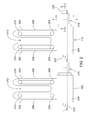
- FIG. 5A This process is illustrated schematically in Figures 5A-5E .
- a first driveshaft 500, a second driveshaft 502, and a third driveshaft 504 are shown supported in a first inner sleeve 222a of a slip clutch of one row unit (not shown), and supported in a second inner sleeve 222b of a slip clutch of an adjacent row unit (not shown).
- the row units and other components are not necessary for this description and therefore have been removed for clarity of illustration.
- the first inner sleeve 222a, the second inner sleeve 222b the first driveshaft 500, the second driveshaft 502, and the third driveshaft 504 are shown in their normal operating position, in which they are coaxial and rotate about a common axis of rotation, communicating power from one driveshaft to another through the inner sleeves.
- the drive shafts are not fixed together. There is no continuous power chain extending from driveshaft to driveshaft.
- the inner sleeves are power conveying elements to transfer power from one driveshaft to the adjacent driveshaft inside the inner sleeves.
- the first inner sleeve 222a and the second inner sleeve 222b are preferably constructed and function the same as the inner sleeves 222 shown in Figures 1-4 . They are shown in Figures 5 A-5E in schematic form. Some of the surface features (such as the apertures that receive the engagement elements 228) have been removed for clarity of illustration in Figures 5A-5E .
- first inner sleeve 222a and second inner sleeve 222b in Figures 5A-5E can be applied to any of the inner sleeves 222 of Figures 1-4 .
- One end (the left end in Figures 5A-5E ) of the first driveshaft 500 has been removed for clarity of illustration.
- the end that has been removed can be (although need not be) connected to another adjacent row unit.
- that adjacent row unit may use another first inner sleeves 222 or another second inner sleeve 222b.
- One end (the right end in Figures 5A-5E ) of the third driveshaft 504 has been removed for clarity of illustration.
- the end that has been removed can be (although need not be) connected to another adjacent row unit.
- that adjacent row unit may use another first inner sleeves 222 or another second inner sleeve 222b.
- driveshaft 502 In the position shown in Figure 5B , the left end of driveshaft 502 is now free with respect to the inner sleeve 222a. It can be translated up and down front to back without being restrained by the inner sleeve 222a. As indicated by the arrow in Figure 5B , the driveshaft 502 can be translated downward at its free end (its left end in Figure 5 ) while remaining restrained at its other end in inner sleeve 222b.
- the row unit having the inner sleeve 222b can be removed in the same manner as the row unit having the inner sleeve 222a by movement in the opposite (i.e. the leftward) direction.
- the inner sleeve 222b includes an abutment 506 along its length that prevents either the right end of the second driveshaft 502 or the left end of third driveshaft 504 (or both of them) to pass completely through the inner sleeve 222b. This would seem to prevent the row unit associated with the inner sleeve 222b from being removed as easily as the row unit associated with the inner sleeve 222a. This is not the case. Once the second driveshaft 502 has been removed (see Figure 5D ) the row unit associated with the inner sleeve 222b can unbolted from the toolbar 106 and slid to the left until it is disconnected from the third driveshaft 504.
- the third driveshaft 504 did not be a sectional driveshaft. In fact, it need not be a sectional driveshaft, just like the first driveshaft 500 need not be a sectional driveshaft.
- any one or all of the inner sleeves 222 can have an internal bore that permits either driveshaft supported in the inner sleeve 222 to translate completely through the inner sleeve as shown in Figures 5A-5E .
- any one or all of the inner sleeves 222 can have an abutment 506 that prevents either one or both of the driveshafts supported in an inner sleeve 222 from being removed using the process shown in Figures 5A-5E . While this arrangement has the disadvantage of preventing easy removal of a row unit, it nonetheless provides the benefit of not requiring a single long driveshaft extending through all (or many) of the row units that will require a tractor or truck to remove.
- the inner sleeve 222 need not have an open passageway that extends completely therethrough (i.e. it need not form a through hole) the abutment 506 can be formed as a wall.
Landscapes
- Life Sciences & Earth Sciences (AREA)
- Environmental Sciences (AREA)
- Harvester Elements (AREA)
- Motor Power Transmission Devices (AREA)
- Mechanical Operated Clutches (AREA)
- Medicines That Contain Protein Lipid Enzymes And Other Medicines (AREA)
- De-Stacking Of Articles (AREA)
Abstract
Description
- The present invention relates generally to agricultural harvesters. More particularly it relates to harvesting heads. Even more particularly it relates to driveshaft arrangements for driving row units of a corn head.
- Corn heads are agricultural implements configured to be supported on the front of a combine harvester. The corn head is typically arranged as a laterally extending transverse frame on which several row units are fixed. The row units are spaced equidistantly across the leading edge of the corn head frame.
- Row units are driven by one or more driveshafts that extend in a transverse direction parallel to the transverse extent of the corn head frame.
- In one common arrangement, shown in
EP 1,820 387 A1 , all of the row units on at least one side of the corn head are driven by a common polygonal driveshaft that can be 15-20 feet long and pass through 6-8 separate row units. - In order to repair the row units, this driveshaft must be removed. The removal process typically requires a farmer to support the corn head on agricultural harvester, unbolt a cover at the outer end of the corn head, attach a chain to the end of the corn head driveshaft, attach the other end of the chain to a tow vehicle, such as a tractor or truck, and then remove the 15-20 foot long corn head driveshaft by pulling it out of its 6-8 row units with the tow vehicle.
- This process takes an extended period of time, and typically two or more people to perform. The replacement process is even more time-consuming, since the long driveshaft must be inserted into the corn head and threaded through the 6-8 row units one at a time.
- Another arrangement, shown in
EP 0 775 437 B2 is for a forage harvester. There are several gearboxes that drive rotating knives and conveyors. The gearboxes have internal driveshafts that are splined at each end and extend outward from either side of the gearbox. Another arrangement, shown inUS 7,640,718 B2 shows several gearboxes for a forage harvester that have short drive shafts extending through the gearboxes and stub axles with universal joints that connect the driveshafts that extend from each gearbox. Another arrangement, shown inDE 103 16 003 A1 shows a parallel drive arrangement for driving row units on corn heads. Another arrangement, shown inUS 6,349,258 B1 illustrate a drive arrangement for driving transversely adjustable row units. - What is needed, therefore, is an improved driveshaft arrangement for a corn head that permits individual row units to be removed and replaced more quickly and easily.
- It is therefore an object of the present invention to provide an improved driveshaft arrangement for a corn head.
- A sectional driveshaft arrangement for a corn head is provided, comprising: a first row unit comprising a first gearbox and a first slip clutch drivingly coupled to the first gearbox; a first driveshaft, the first driveshaft having a first end and a second end opposite the first end, wherein the first end terminates within the first slip clutch; and a second driveshaft, the second driveshaft having a third end and a fourth end opposite to the third end, wherein the third end terminates within the first slip clutch; wherein the first slip clutch is configured to be driven in rotation by the first driveshaft and to drive the second driveshaft in rotation.
- The sectional driveshaft arrangement for a corn head may further comprise a second row unit adjacent to the first row unit, the second row unit may comprise a second gearbox and a second slip clutch, and the fourth end of the second driveshaft may terminate within the second slip clutch, and the second slip clutch may be configured to be driven in rotation by the second driveshaft.
- The sectional driveshaft arrangement for a corn head may further comprise a third driveshaft, the third driveshaft may have a fifth end and a sixth end opposite the fifth end;
and the fifth end may terminate in the second slip clutch and the second slip clutch may drive the third driveshaft in rotation. - The sectional driveshaft arrangement for a corn head may further comprise a third row unit that is adjacent to the second row unit, and the third row unit may comprise a third gearbox and a third slip clutch, and the sixth end may terminate in the third slip clutch, and the third slip clutch may be configured to be driven in rotation by the third driveshaft.
- The first slip clutch may comprise an inner sleeve that receives and supports the first end and the third end, and the inner sleeve may be configured to transmit power from the first end to the third end.
- The inner sleeve may have a through hole with an inner surface that, in axial cross-section, defines a first polygon, and the first end and the third end may have outer surfaces that, in axial cross-section, define a second polygon, such that the second polygon may be contained within boundaries of the first polygon, and such that the second polygon is not capable of being rotated with respect to the first polygon while staying contained within boundaries of the first polygon.
- The first end may be configured to be received in a first side of the inner sleeve and to axially translate through the inner sleeve until the first end passes entirely through the inner sleeve and extends at least partially out a second side of the inner sleeve.
- The third end may be configured to be received in the second side of the inner sleeve and axially translate with respect to the inner sleeve until the third end passes entirely through the inner sleeve and extends at least partially out the first side of the inner sleeve.
- The first slip clutch may have an abutment that is disposed to prevent the first end or the third end from passing completely through the first slip clutch.
- The first slip clutch may define a first aperture extending into the first slip clutch from one side of the first slip clutch, and wherein the first slip clutch may define a second aperture extending into the first slip clutch from a side of the first slip clutch that is opposite the one side, and wherein the first end is configured to be inserted into the first aperture, and the second end is configured to be inserted into the second aperture.
- The first end has a first rotational axis and the second end has a second rotational axis, and further wherein the first rotational axis and the second rotational axis are coaxial.
- These and other objects, features and advantages of the invention will become apparent to one skilled in the art upon reading the following description in view of the drawings.
-
Figure 1 is a schematic plan view of a corn head in accordance with the present invention. -
Figure 2 is a detailed view of two adjacent row units of the corn head ofFigure 1 . -
Figure 3 is a cross-sectional view of a slip clutch of the row units ofFigure 2 taken at section line 3-3 inFigure 2 . -
Figure 4 is a cross-sectional view of the slip clutch of the row units ofFigure 2 taken at section line 4-4 inFigure 2 . -
Figure 5A-5E illustrate successive positions of two inner sleeves of two corresponding row units and a sectional driveshaft showing a method of removing the two corresponding row units, by sliding an inner sleeve of a slip clutch along a driveshaft. - Referring now to
Figure 1 , acorn head 100 comprises aframe 102,toolbar supports 104,toolbar 106,row unit 108,row unit 110,row unit 112,row unit 114,row unit 116,row unit 118,row unit 120, androw unit 122. -
Frame 102 is elongate member extending laterally, and generally perpendicular to the direction of travel "V" of thecorn head 100. Frame 102 (and hence the corn head 100) is supported on afeederhouse 128 that extends forward from the front end of a combine harvester (not shown). - Toolbar
supports 104 are fixed toframe 102 and extend forward therefrom. - Toolbar 106 extends laterally and parallel to
frame 102.Toolbar 106 extends substantially the entire width of the corn head. -
Row unit 108,row unit 110,row unit 112,row unit 114,row unit 116,row unit 118,row unit 120, androw unit 122 are fixed to thetoolbar 106 and extend forward therefrom. The row units are identically constructed. The row units are mounted on the toolbar a constant spacing apart of 20-36 inches. - The
corn head 100 is supported on thefeederhouse 128 to be carried through the agricultural field harvesting crop in the direction "V". The row units are driven elements, supplied with power from the combine harvester (not shown) through an arrangement of belts, shafts, pulleys, and hydraulics. - In a conventional corn head, a single driveshaft extends inwardly from the left end of the corn head to the center of the corn head. This driveshaft drives all of the row units on the left side of the corn head. In a similar fashion, a single driveshaft extends inwardly from the right end of the corn head to the center of the corn head. This driveshaft drives all of the row units on the right side of the corn head.
- The arrangement of the present invention is shown in greater detail in
Figure 2 . InFigure 2 , twoadjacent row units corn head 100. - The drive arrangement between
row unit 108 androw unit 110 is the same as the drive arrangement betweenrow unit 110 androw unit 112, and betweenrow unit 112 androw unit 114 on the left side of thecorn head 100. All of the row units are connected, collectively, with two or more driveshafts, wherein each driveshaft is coaxial with all the other driveshafts. - The drive arrangement between
row unit 108 androw unit 110 is also the same as the drive arrangement betweenrow unit 116 androw unit 118, betweenrow unit 118 androw unit 120, and betweenrow unit 120 androw unit 122. On the right side of thecorn head 100. - In short, every pair of adjacent row units (except the two middle row units:
row unit 114 and row unit 116) are coupled together using the drive arrangement shown inFigure 2 . - The two endmost row units (
row unit 108 and row unit 122) are driven by a driveshaft that is coupled to a remote source of power. This remote source of power is the engine provided in the combine harvester (not shown). - A typical arrangement for supplying power to the endmost row units can be found in
EP 1,820,387 A1 which is incorporated herein by reference for all that it teaches. - In
Figure 2 , each row unit comprises agearbox 200, twoarms gathering chains 206, twodrive sprockets 208, twoidler sprockets 210 and a slip clutch. - The two
arms gearbox 200 and extend forwardly therefrom. Each of thearms gathering chain 206 that is formed in an endless loop and is supported on and driven by adrive sprocket 208 at the rear of each gatheringchain 206. Anidler sprocket 210 is disposed at the forward end of each of thearms gathering chain 206 wraps. - A
gap 212, open at a forward-facing end, is elongate an extends parallel to the direction of travel "V", and is provided between the twoarms corn head 100 is driven over the field, the operator aligns the corn head such that a row of crops passes into thegap 212. The gatheringchains 206 are driven by thegearbox 200 such that they pull the stalk of each plant in the row of crops rearward. Two stalk rolls (not shown) extend forward from thegearbox 200 underneath the two forwardly extendingarms arms chains 206 carry the ears of corn rearward into a conveyor (not shown). The conveyor carries the ears of corn to a center portion of thecorn head 100. A conveyor disposed in the feederhouse 128 carries the ears of corn rearward, through thefeederhouse 128, and into the combine harvester (not shown). Thegearbox 200 ofrow unit 108 is fixed to and is driven by aslip clutch 214. Thegearbox 200 ofrow unit 110 is fixed to and is driven by aslip clutch 216. Theslip clutch 214 and theslip clutch 216 are identically constructed. Either slip clutch is exemplary of all the other slip clutches that are coupled to and drive the other row units. Theslip clutch 214 and theslip clutch 216 are coupled together with adriveshaft 218. Thedriveshaft 218 terminates at its left end within theslip clutch 214 and terminates at its right end within theslip clutch 216. -
Driveshaft 218 is driven at its left end by the engine of the combine harvester.Driveshaft 218 terminates inside slip clutch 214 at its right end and drives theslip clutch 214. -
Driveshaft 220 is a sectional driveshaft. The left end ofdriveshaft 220 terminatesinside slip clutch 214 and is driven byslip clutch 214. The right end ofdriveshaft 220 terminatesinside slip clutch 216 and drives slip clutch 216. Slip clutch 214 and slip clutch 216 are adjacent. -
Figures 3 and4 illustrate features of theslip clutch 214. All the slip clutches are identically constructed. Thus, all the statements herein regarding the operation of slip clutch 214 are true of all the other slip clutches ofcorn head 100. - The
slip clutch 214 comprises aninner sleeve 222, anouter sleeve 224, and severaltorque transfer members 226 that extend between theinner sleeve 222 and theouter sleeve 224. - The
inner sleeve 222 has the general form of a hollow cylinder. It is disposed within and concentric with theouter sleeve 224, which also has the general form of a hollow cylinder. -
Torque transfer members 226 extend between and couple theinner sleeve 222 and theouter sleeve 224. A typicaltorque transfer member 226 includes anengagement element 228 and aspring 230.Spring 230 is disposed inside an aperture in theinner sleeve 222 and extends outwardly therefrom.Spring 230 abuts anengagement element 228 associated with thespring 230. Eachspring 230 pushes its associatedengagement element 228 into engagement with theouter sleeve 224. - The
inner sleeve 222 and theouter sleeve 224 rotate freely with respect to each other. Thetorque transfer members 226 extend between them and compel theouter sleeve 224 to rotate with theinner sleeve 222 when thedriveshaft 218 drives theinner sleeve 222 in rotation. - The
outer sleeve 224, in turn, is drivingly connected to the connected to the two drivesprockets 208 to drive them in rotation. Theouter sleeve 224, is also drivingly connected to the two stalk rolls (not shown) to drive them in rotation. - If the
row unit 108 becomes jammed, it will resist the rotation of theouter sleeve 224. This, in turn, will cause an increased reactive torque to be applied by theouter sleeve 224 to theinner sleeve 222. This increased reactive torque, in turn, will force theengagement elements 228 radially inwardly toward the axis of rotation of the two sleeves, and (if the reactive torque is high enough) will permit theouter sleeve 224 to stop as theinner sleeve 222 is driven in rotation by thedriveshaft 218. In this state, theslip clutch 214 is said to be "slipping". - The inner surface of the
inner sleeve 222 is noncircular. In the embodiment shown here it is polygonal. It is a regular polygon. It is hexagonal. Thedriveshaft 218 and thedriveshaft 220 have the same cross sectional profile. They are both noncircular polygons, regular polygons and hexagons. - The external surfaces of the
driveshaft 218 and thedriveshaft 220 match the inside surface of theinner sleeve 222. They are dimensioned such that the outer surface of thedriveshaft 218 and the outer surface of thedriveshaft 220 engage the inner surface of theinner sleeve 222. This surface-to-surface engagement is such that thedriveshaft 218 drives theinner sleeve 222 in rotation whenever thedriveshaft 218 rotates, and such that theinner sleeve 222, in turn, drives thedriveshaft 220 in rotation whenever theinner sleeve 222 rotates. - The hexagon that forms the outer surface of
driveshaft 218 anddriveshaft 220 is received inside the boundaries of the hexagon that forms the boundaries of the inner surface ofinner sleeve 222. They are very close to the same size, however, and the hexagonal outer surface of the driveshafts cannot be rotated within the hexagonal inner surface of theinner sleeve 222 because the surfaces interfere with each other. it is this interference and prevention of rotation that permitsdriveshaft 218 to drive theinner sleeve 222 and permits theinner sleeve 222 to rotatedriveshaft 220 in turn. The apertures ininner sleeve 222 in whichdriveshaft 218 and driveshaft 20 are inserted have the same polygonal shape in one embodiment. Thus,driveshaft 218 anddriveshaft 220 can have the same polygonal shape and therefore be fitted interchangeably in either aperture. - A sliding clearance may be provided between the outer surfaces of the
driveshaft 218 and thedriveshaft 220 and the inner surface of theinner sleeve 222 to permit thedriveshaft 218 and thedriveshaft 220 to be translated axially, by hand, to the left or to the right with respect to theinner sleeve 222 and thereby to permit thedriveshaft 218 in thedriveshaft 220 to be removed by hand from theslip clutch 214 and therefore also be removed from therow unit 108. - As shown herein, all of the drive shafts that couple the row units are coaxial. Furthermore they all rotate around a common axis of rotation. Furthermore, the apertures that pass into each side of the
inner sleeves 222 and support driveshafts are all coaxial with each other, and with all of the drive shafts. Furthermore, the apertures that pass into each side of theinner sleeves 222 and support driveshafts all rotate about a common rotational axis. - Power is transmitted from the
driveshaft 218 driven by the engine of the combine harvester to theinner sleeve 222 of theslip clutch 214. The inner sleeve of theslip clutch 214, in turn, drives theouter sleeve 224 of theslip clutch 214 and also drives thedriveshaft 220. Theouter sleeve 224 of theslip clutch 214, in turn, drives the driven elements (the gathering chains 206) of therow unit 108. Thedriveshaft 220, in turn, drives the inner sleeve of the slip clutch associated with therow unit 110. The inner sleeve of the slip clutch associated withrow unit 110, in turn, drives the driven elements (the gathering chains 206) of therow unit 110. The inner sleeve of the slip clutch associated withrow unit 110, also drives the sectional driveshaft 232 (shown cut away inFigures 2 and3 ), which is in turn connected to the next row unit (row unit 112) in the same manner. A similar sectional driveshaft is provided between therow unit 112 and therow unit 114 that is identical to thedriveshaft 220 and functions in the identical manner. - The discussion in the previous paragraphs have addressed the drive arrangement of the row units on the left side of the
corn head 100. The drive arrangement of the row units on the right side of thecorn head 100 is identical, but in mirror image form. The outermost row unit on the right hand side (i.e. row unit 222) is driven at its right side by a driveshaft that is identical to thedriveshaft 118 and is identically connected to and driven by the engine of the combine harvester. - One advantage to the foregoing arrangement is the fact that long row unit driveshafts need not be stocked or shipped. Each row unit driveshaft need only be as long as the standard row unit spacing of the row units, which typically varies between 20 and 36 inches in length.
- Another advantage to the foregoing arrangement is the elimination of driveshaft couplers. In some previous row unit drive arrangements, an extremely long row unit driveshaft is manufactured and shipped in two (or more) sections, depending upon the overall length of the driveshaft. Each section of the two (or more) sections would be inserted through the slip clutches of the row units until the two sections of driveshaft abutted each other between two adjacent row units. At this point, a driveshaft coupler (in the form of a multi-piece collar) is placed around the abutting ends of the driveshaft and the coupler is firmly attached to both driveshaft sections. By providing sectional drive shafts that extend between and terminate at the slip clutches of each adjacent row unit, the need for a separate driveshaft coupler can be eliminated.
- An advantage of one specific embodiment of the foregoing arrangement is the ease with which individual row units can be removed for repair or replacement. If the inner sleeve of a row unit has an inner surface with a constant cross-section over its entire length, either of the two driveshafts supported in the inner sleeve can translated completely through the inner sleeve without undue difficulty. In this manner, a single row unit can be removed while the adjacent row units remain bolted in place.
- This process is illustrated schematically in
Figures 5A-5E . InFigure 5A , afirst driveshaft 500, asecond driveshaft 502, and athird driveshaft 504 are shown supported in a firstinner sleeve 222a of a slip clutch of one row unit (not shown), and supported in a secondinner sleeve 222b of a slip clutch of an adjacent row unit (not shown). The row units and other components are not necessary for this description and therefore have been removed for clarity of illustration. - In
Figure 5A , the firstinner sleeve 222a, the secondinner sleeve 222b thefirst driveshaft 500, thesecond driveshaft 502, and thethird driveshaft 504 are shown in their normal operating position, in which they are coaxial and rotate about a common axis of rotation, communicating power from one driveshaft to another through the inner sleeves. Note that the drive shafts are not fixed together. There is no continuous power chain extending from driveshaft to driveshaft. The inner sleeves are power conveying elements to transfer power from one driveshaft to the adjacent driveshaft inside the inner sleeves. - The first
inner sleeve 222a and the secondinner sleeve 222b are preferably constructed and function the same as theinner sleeves 222 shown inFigures 1-4 . They are shown inFigures 5 A-5E in schematic form. Some of the surface features (such as the apertures that receive the engagement elements 228) have been removed for clarity of illustration inFigures 5A-5E . - Furthermore, the arrangements and capabilities of the through holes of first
inner sleeve 222a and secondinner sleeve 222b inFigures 5A-5E can be applied to any of theinner sleeves 222 ofFigures 1-4 . - One end (the left end in
Figures 5A-5E ) of thefirst driveshaft 500 has been removed for clarity of illustration. The end that has been removed can be (although need not be) connected to another adjacent row unit. In one arrangement, that adjacent row unit may use another firstinner sleeves 222 or another secondinner sleeve 222b. - One end (the right end in
Figures 5A-5E ) of thethird driveshaft 504 has been removed for clarity of illustration. The end that has been removed can be (although need not be) connected to another adjacent row unit. In one arrangement, that adjacent row unit may use another firstinner sleeves 222 or another secondinner sleeve 222b. - In
Figure 5B , the bolts (not shown) that fix the row unit havinginner sleeve 222a to thetoolbar 106 have been loosened, and the entire row unit (including theinner sleeve 222a) has been slid to the left. In this position, the previously adjacent ends ofdriveshaft 500 anddriveshaft 502 are removed from theinner sleeve 222a. This is only possible ifdriveshaft 500 can be slid entirely through theinner sleeve 222a until it extends at least partially out the other side of theinner sleeve 222a. - In the position shown in
Figure 5B , the left end ofdriveshaft 502 is now free with respect to theinner sleeve 222a. It can be translated up and down front to back without being restrained by theinner sleeve 222a. As indicated by the arrow inFigure 5B , thedriveshaft 502 can be translated downward at its free end (its left end inFigure 5 ) while remaining restrained at its other end ininner sleeve 222b. - In the position shown in
Figure 5C , the free (left) end of thesecond driveshaft 502 is pivoted downward and away from theinner sleeve 222a while the other end of thesecond driveshaft 502 still remains restrained and contained within theinner sleeve 222b. In this position, there is sufficient clearance at the free end ofsecond driveshaft 502 to permit it to be withdrawn from theinner sleeve 222b in a direction parallel to the longitudinal axis of thesecond driveshaft 502, which is indicated by the arrow inFigure 5C . - In the position shown in
Figure 5D , thesecond driveshaft 502 is completely withdrawn from theinner sleeve 222b. In this position, with thesecond driveshaft 502 completely removed, the row unit havinginner sleeve 222a can be translated back to the right (inFigure 5D ) along thetoolbar 106 in the direction indicated by the arrows adjacent to theinner sleeve 222a. - In the position shown in
Figure 5E , the row unit containing theinner sleeve 222a is translated rightward until the right end ofdriveshaft 500 is completely removed from theinner sleeve 222a and the row unit of which it forms a part. Now that the row unit is completely separate from thefirst driveshaft 500 and thesecond driveshaft 502, it can be lowered to the ground as indicated by the directional arrow underneath theinner sleeve 222a. Note that thefirst driveshaft 500 need not be a sectional driveshaft. It can extend through and drive the slip clutches of several adjacent row units and therefore not be able to pivot up or down, yet the row unit associated with theinner sleeve 222a can still be removed from thefirst driveshaft 500 by translating the row unit associated withinner sleeve 222a rightwardly as shown in the transition betweenFigure 5D and Figure 5E . - Note also that once the
second driveshaft 502 has been removed (seeFigure 5D ) the row unit having theinner sleeve 222b can be removed in the same manner as the row unit having theinner sleeve 222a by movement in the opposite (i.e. the leftward) direction. - The
inner sleeve 222b includes anabutment 506 along its length that prevents either the right end of thesecond driveshaft 502 or the left end of third driveshaft 504 (or both of them) to pass completely through theinner sleeve 222b. This would seem to prevent the row unit associated with theinner sleeve 222b from being removed as easily as the row unit associated with theinner sleeve 222a. This is not the case. Once thesecond driveshaft 502 has been removed (seeFigure 5D ) the row unit associated with theinner sleeve 222b can unbolted from thetoolbar 106 and slid to the left until it is disconnected from thethird driveshaft 504. It can then be lowered to the ground and removed entirely from thecorn head 100 in the same manner as the row unit associated with theinner sleeve 222a. Similarly, thethird driveshaft 504 did not be a sectional driveshaft. In fact, it need not be a sectional driveshaft, just like thefirst driveshaft 500 need not be a sectional driveshaft. - Having described the preferred embodiments, it will become apparent that various modifications can be made without departing from the scope of the invention as defined in the accompanying claims.
- For example, any one or all of the
inner sleeves 222 can have an internal bore that permits either driveshaft supported in theinner sleeve 222 to translate completely through the inner sleeve as shown inFigures 5A-5E . - As another example, any one or all of the
inner sleeves 222 can have anabutment 506 that prevents either one or both of the driveshafts supported in aninner sleeve 222 from being removed using the process shown inFigures 5A-5E . While this arrangement has the disadvantage of preventing easy removal of a row unit, it nonetheless provides the benefit of not requiring a single long driveshaft extending through all (or many) of the row units that will require a tractor or truck to remove. By permitting adjacent drive shafts to be coupled within and coupled by theinner sleeve 222 of a row unit even if that row unit cannot slide back and forth on either driveshaft, this arrangement still provides the benefit of not requiring a separate, additional mechanical coupling to join the ends of two abutting driveshafts between two adjacent row units. - As another example, the
inner sleeve 222 need not have an open passageway that extends completely therethrough (i.e. it need not form a through hole) theabutment 506 can be formed as a wall.
Claims (14)
- A sectional driveshaft arrangement for a corn head (100), the arrangement comprising:a first row unit (108, 110, 112, 118, 120, 122) comprising a first gearbox (200) and a first slip clutch (214, 216) drivingly coupled to the first gearbox (200);a first driveshaft (218, 220, 232), the first driveshaft having a first end and a second end opposite the first end, wherein the first end terminates within the first slip clutch (214, 216); anda second driveshaft (218, 220, 232), the second driveshaft having a third end and a fourth end opposite to the third end, wherein the third end terminates within the first slip clutch (214, 216);wherein the first slip clutch (214, 216) is configured to be driven in rotation by the first driveshaft (218, 220, 232) and to drive the second driveshaft (220, 232) in rotation.
- The sectional driveshaft arrangement for a corn head (100) of Claim 1, further comprising:a second row unit (110,112, 114, 116, 118, 120) adjacent to the first row unit (108, 110, 112, 118, 120, 122), the second row unit comprising a second gearbox (200) and a second slip clutch (216), wherein the fourth end of the second driveshaft (220, 232) terminates within the second slip clutch, and further wherein the second slip clutch (216) is configured to be driven in rotation by the second driveshaft (220, 232).
- The sectional driveshaft arrangement for a corn head (100) of claim 2, further comprising:a third driveshaft (232), the third driveshaft (232) having a fifth end and having a sixth end opposite the fifth end;wherein the fifth end terminates in the second slip clutch (216) and further wherein the second slip clutch drives the third driveshaft in rotation.
- The sectional driveshaft arrangement for a corn head (100) of claim 3, further comprising:a third row unit (112, 114, 116, 118) adjacent to the second row unit (110,112, 118, 120), the third row unit comprising a third gearbox (200) and a third slip clutch, wherein the sixth end terminates in the third slip clutch, and further wherein the third slip clutch is configured to be driven in rotation by the third driveshaft (232).
- The sectional driveshaft arrangement for a corn head (100) of claim 1, wherein the first slip clutch (214, 216) comprises an inner sleeve (222) that receives and supports the first end and the third end, and further wherein the inner sleeve (222) transmits power from the first end to the third end.
- The sectional driveshaft arrangement for a corn head (100) of Claim 5, wherein the inner sleeve (222) has a through hole with an inner surface that, in axial cross-section, defines a first polygon, and further wherein the first end and the third end have outer surfaces that, in axial cross-section, define a second polygon, and further in which the second polygon can be disposed within the boundaries of the first polygon, and further in which the second polygon is not capable of being rotated with respect to the first polygon while staying within the boundaries of the first polygon.
- The sectional driveshaft arrangement for a corn head (100) of Claim 5, wherein the first end is configured to be received in a first side of the inner sleeve (222) and to axially translate through the inner sleeve (222) until the first end passes entirely through the inner sleeve (222) and extends at least partially out a second side of the inner sleeve (222).
- The sectional driveshaft arrangement for a corn head (100) of Claim 7, wherein the third end is configured to be received in the second side of the inner sleeve (222) and to axially translate with respect to the inner sleeve (222) until the third end passes entirely through the inner sleeve (222) and extends at least partially out the first side of the inner sleeve (222).
- The sectional driveshaft arrangement for a corn head (100) of Claim 1, wherein the first slip clutch has an abutment (506) disposed to prevent the first end or the third end from passing completely through the first slip clutch.
- The sectional driveshaft arrangement for a corn head (100) of Claim 1, wherein the first slip clutch defines a first aperture extending into the first slip clutch from one side of the first slip clutch, and wherein the first slip clutch defines a second aperture extending into the first slip clutch from a side of the first slip clutch that is opposite the one side, and wherein the first end is inserted into the first aperture, and the second end is inserted into the second aperture.
- The sectional driveshaft arrangement for a corn head (100) of Claim 10, wherein the first and has a first rotational axis and the second end has a second rotational axis, and further wherein the first rotational axis and the second rotational axis are coaxial.
- The sectional driveshaft arrangement for a corn head (100) of Claim 6, wherein the first polygon and the second polygon are regular polygons.
- The sectional driveshaft arrangement for a corn head (100) of Claim 6, wherein the first polygon and the second polygon are hexagons.
- A cornhead (100) comprising a driveshaft arrangement according to one of the preceding claims.
Applications Claiming Priority (1)
| Application Number | Priority Date | Filing Date | Title |
|---|---|---|---|
| US13/848,397 US9072221B2 (en) | 2013-03-21 | 2013-03-21 | Sectional driveshaft arrangement for a corn head |
Publications (3)
| Publication Number | Publication Date |
|---|---|
| EP2781149A2 true EP2781149A2 (en) | 2014-09-24 |
| EP2781149A3 EP2781149A3 (en) | 2014-11-26 |
| EP2781149B1 EP2781149B1 (en) | 2016-01-20 |
Family
ID=50151143
Family Applications (1)
| Application Number | Title | Priority Date | Filing Date |
|---|---|---|---|
| EP14155752.0A Active EP2781149B1 (en) | 2013-03-21 | 2014-02-19 | Sectional driveshaft arrangement for a corn head |
Country Status (6)
| Country | Link |
|---|---|
| US (1) | US9072221B2 (en) |
| EP (1) | EP2781149B1 (en) |
| CN (1) | CN104054460B (en) |
| AU (1) | AU2014201450B2 (en) |
| BR (1) | BR102014006458B1 (en) |
| RU (1) | RU2662188C2 (en) |
Cited By (2)
| Publication number | Priority date | Publication date | Assignee | Title |
|---|---|---|---|---|
| EP3479674A1 (en) * | 2017-11-06 | 2019-05-08 | Maschinenfabrik Bernard Krone GmbH & Co. KG | Agricultural harvester |
| EP4381933A1 (en) * | 2022-12-09 | 2024-06-12 | CNH Industrial America LLC | Power transfer arrangement including coupling clutches for an agricultural vehicle |
Families Citing this family (3)
| Publication number | Priority date | Publication date | Assignee | Title |
|---|---|---|---|---|
| DE102013100495A1 (en) * | 2013-01-18 | 2014-07-24 | Claas Selbstfahrende Erntemaschinen Gmbh | Attachment for harvesting corn |
| US10820509B2 (en) | 2017-08-08 | 2020-11-03 | Cnh Industrial America Llc | Foldable corn head |
| US11161494B2 (en) | 2020-03-16 | 2021-11-02 | Deere & Company | Sensing system for agricultural machine |
Citations (5)
| Publication number | Priority date | Publication date | Assignee | Title |
|---|---|---|---|---|
| EP0775437B1 (en) | 1995-11-27 | 2001-05-30 | Claas Saulgau Gmbh | Agricultural device for harvesting stalk crops |
| US6349258B1 (en) | 1998-12-23 | 2002-02-19 | Thomson Csf-Sextant | Method for horizontal routing of an aircraft between two waypoints |
| DE10316003A1 (en) | 2003-04-07 | 2005-07-07 | Claas Saulgau Gmbh | Picking attachment for harvesting fruit stalks |
| EP1820387A1 (en) | 2006-02-17 | 2007-08-22 | Deere & Company | Combine head with a drive assembly |
| US7640718B2 (en) | 2006-05-30 | 2010-01-05 | Claas Saulgau Gmbh | Attachment for harvesting stalk-like goods where each cutting and conveying element is controlled individually |
Family Cites Families (8)
| Publication number | Priority date | Publication date | Assignee | Title |
|---|---|---|---|---|
| US4227366A (en) * | 1979-08-06 | 1980-10-14 | Sperry Corporation | Corn header drive system |
| US4244162A (en) * | 1979-08-06 | 1981-01-13 | Sperry Corporation | Row unit frame |
| SU1271423A1 (en) * | 1984-05-17 | 1986-11-23 | Производственное объединение "Херсонский комбайновый завод им.Г.И.Петровского" | Trailed maiz-harvesting machine |
| DE19951644A1 (en) * | 1999-10-27 | 2001-05-17 | Kemper Gmbh Maschf | Agricultural machine, in particular mower |
| CN2906206Y (en) * | 2006-02-24 | 2007-05-30 | 山东巨明机械有限公司 | Transmission gear tank for snapping roll of corn harvester |
| US20080015034A1 (en) * | 2006-07-17 | 2008-01-17 | Deere & Company, A Delaware Corporation | Torque limiter for a harvester row unit |
| CN201613323U (en) * | 2010-03-21 | 2010-10-27 | 徐州压力机械有限公司 | Driving device for forging and pressing equipment moving platform |
| CN102960126A (en) * | 2012-11-28 | 2013-03-13 | 萝北县新利民农业机械制造有限公司 | Power drive structure for harvesting platform of backpack corn harvester |
-
2013
- 2013-03-21 US US13/848,397 patent/US9072221B2/en active Active
-
2014
- 2014-02-19 EP EP14155752.0A patent/EP2781149B1/en active Active
- 2014-03-13 AU AU2014201450A patent/AU2014201450B2/en not_active Ceased
- 2014-03-18 BR BR102014006458A patent/BR102014006458B1/en active IP Right Grant
- 2014-03-20 RU RU2014110781A patent/RU2662188C2/en active
- 2014-03-21 CN CN201410108880.4A patent/CN104054460B/en active Active
Patent Citations (5)
| Publication number | Priority date | Publication date | Assignee | Title |
|---|---|---|---|---|
| EP0775437B1 (en) | 1995-11-27 | 2001-05-30 | Claas Saulgau Gmbh | Agricultural device for harvesting stalk crops |
| US6349258B1 (en) | 1998-12-23 | 2002-02-19 | Thomson Csf-Sextant | Method for horizontal routing of an aircraft between two waypoints |
| DE10316003A1 (en) | 2003-04-07 | 2005-07-07 | Claas Saulgau Gmbh | Picking attachment for harvesting fruit stalks |
| EP1820387A1 (en) | 2006-02-17 | 2007-08-22 | Deere & Company | Combine head with a drive assembly |
| US7640718B2 (en) | 2006-05-30 | 2010-01-05 | Claas Saulgau Gmbh | Attachment for harvesting stalk-like goods where each cutting and conveying element is controlled individually |
Cited By (3)
| Publication number | Priority date | Publication date | Assignee | Title |
|---|---|---|---|---|
| EP3479674A1 (en) * | 2017-11-06 | 2019-05-08 | Maschinenfabrik Bernard Krone GmbH & Co. KG | Agricultural harvester |
| EP4381933A1 (en) * | 2022-12-09 | 2024-06-12 | CNH Industrial America LLC | Power transfer arrangement including coupling clutches for an agricultural vehicle |
| US12565914B2 (en) | 2022-12-09 | 2026-03-03 | Cnh Industrial America Llc | Power transfer arrangement including coupling clutches for an agricultural vehicle |
Also Published As
| Publication number | Publication date |
|---|---|
| US9072221B2 (en) | 2015-07-07 |
| EP2781149A3 (en) | 2014-11-26 |
| CN104054460A (en) | 2014-09-24 |
| BR102014006458A8 (en) | 2019-09-10 |
| AU2014201450A1 (en) | 2014-10-09 |
| BR102014006458B1 (en) | 2020-04-22 |
| AU2014201450B2 (en) | 2017-06-15 |
| BR102014006458A2 (en) | 2016-08-09 |
| EP2781149B1 (en) | 2016-01-20 |
| RU2014110781A (en) | 2015-09-27 |
| US20140283490A1 (en) | 2014-09-25 |
| RU2662188C2 (en) | 2018-07-24 |
| CN104054460B (en) | 2018-05-22 |
Similar Documents
| Publication | Publication Date | Title |
|---|---|---|
| EP2781149B1 (en) | Sectional driveshaft arrangement for a corn head | |
| US7937918B1 (en) | Drive arrangement for corn head equipped with or without a corn stalk chopper | |
| CN105432227B (en) | Power take-off drive assembly for a corn header of an agricultural harvester | |
| US8973345B2 (en) | Drive assembly for an agricultural harvesting platform | |
| EP1382237B1 (en) | Feed conveyor/rock trap and header drive for an agricultural harvesting machine. | |
| US6381933B1 (en) | Shaft coupling with tapered splines for a pull-type forage harvester | |
| EP2687079A2 (en) | Row-independent auxiliary device for harvesting stalk crops | |
| US7213488B2 (en) | Three way swivel divider gearbox for agricultural drive systems | |
| US10582661B2 (en) | System and method for converting cutting and gathering system of a corn head | |
| EP2084954B1 (en) | Stalk roll | |
| DE102008033917B4 (en) | Connecting arrangement, between a feed roller and a transmission of a forage harvester | |
| US7669396B2 (en) | Timing crank and cylindrical conveyor for an agricultural harvester | |
| CA2324739A1 (en) | Agricultural implement, in particular a mowing machine | |
| RU2665620C2 (en) | Double ended extendable driveshaft for auto header hookup | |
| EP3466242B1 (en) | Agricultural harvesting head with nested draper belt drive | |
| US20050193705A1 (en) | Variable speed drive for oblique feeding drums | |
| US2877664A (en) | Forage harvester drive means | |
| JPH0140441Y2 (en) | ||
| CN111853204A (en) | Telescopic shaft shield with quick connect assembly | |
| CN101252829B (en) | Combine harvester | |
| BRPI0605273B1 (en) | Improvements made in automotive forage equipment |
Legal Events
| Date | Code | Title | Description |
|---|---|---|---|
| PUAI | Public reference made under article 153(3) epc to a published international application that has entered the european phase |
Free format text: ORIGINAL CODE: 0009012 |
|
| 17P | Request for examination filed |
Effective date: 20140219 |
|
| AK | Designated contracting states |
Kind code of ref document: A2 Designated state(s): AL AT BE BG CH CY CZ DE DK EE ES FI FR GB GR HR HU IE IS IT LI LT LU LV MC MK MT NL NO PL PT RO RS SE SI SK SM TR |
|
| AX | Request for extension of the european patent |
Extension state: BA ME |
|
| PUAL | Search report despatched |
Free format text: ORIGINAL CODE: 0009013 |
|
| AK | Designated contracting states |
Kind code of ref document: A3 Designated state(s): AL AT BE BG CH CY CZ DE DK EE ES FI FR GB GR HR HU IE IS IT LI LT LU LV MC MK MT NL NO PL PT RO RS SE SI SK SM TR |
|
| AX | Request for extension of the european patent |
Extension state: BA ME |
|
| RIC1 | Information provided on ipc code assigned before grant |
Ipc: A01D 69/06 20060101ALI20141017BHEP Ipc: A01D 69/08 20060101ALI20141017BHEP Ipc: A01D 45/02 20060101AFI20141017BHEP |
|
| R17P | Request for examination filed (corrected) |
Effective date: 20150526 |
|
| RBV | Designated contracting states (corrected) |
Designated state(s): AL AT BE BG CH CY CZ DE DK EE ES FI FR GB GR HR HU IE IS IT LI LT LU LV MC MK MT NL NO PL PT RO RS SE SI SK SM TR |
|
| GRAP | Despatch of communication of intention to grant a patent |
Free format text: ORIGINAL CODE: EPIDOSNIGR1 |
|
| INTG | Intention to grant announced |
Effective date: 20150806 |
|
| GRAS | Grant fee paid |
Free format text: ORIGINAL CODE: EPIDOSNIGR3 |
|
| GRAA | (expected) grant |
Free format text: ORIGINAL CODE: 0009210 |
|
| AK | Designated contracting states |
Kind code of ref document: B1 Designated state(s): AL AT BE BG CH CY CZ DE DK EE ES FI FR GB GR HR HU IE IS IT LI LT LU LV MC MK MT NL NO PL PT RO RS SE SI SK SM TR |
|
| REG | Reference to a national code |
Ref country code: GB Ref legal event code: FG4D |
|
| REG | Reference to a national code |
Ref country code: CH Ref legal event code: EP |
|
| REG | Reference to a national code |
Ref country code: IE Ref legal event code: FG4D |
|
| REG | Reference to a national code |
Ref country code: AT Ref legal event code: REF Ref document number: 771264 Country of ref document: AT Kind code of ref document: T Effective date: 20160215 |
|
| REG | Reference to a national code |
Ref country code: DE Ref legal event code: R096 Ref document number: 602014000755 Country of ref document: DE |
|
| REG | Reference to a national code |
Ref country code: LT Ref legal event code: MG4D Ref country code: NL Ref legal event code: MP Effective date: 20160120 |
|
| REG | Reference to a national code |
Ref country code: AT Ref legal event code: MK05 Ref document number: 771264 Country of ref document: AT Kind code of ref document: T Effective date: 20160120 |
|
| PG25 | Lapsed in a contracting state [announced via postgrant information from national office to epo] |
Ref country code: NL Free format text: LAPSE BECAUSE OF FAILURE TO SUBMIT A TRANSLATION OF THE DESCRIPTION OR TO PAY THE FEE WITHIN THE PRESCRIBED TIME-LIMIT Effective date: 20160120 |
|
| PG25 | Lapsed in a contracting state [announced via postgrant information from national office to epo] |
Ref country code: GR Free format text: LAPSE BECAUSE OF FAILURE TO SUBMIT A TRANSLATION OF THE DESCRIPTION OR TO PAY THE FEE WITHIN THE PRESCRIBED TIME-LIMIT Effective date: 20160421 Ref country code: NO Free format text: LAPSE BECAUSE OF FAILURE TO SUBMIT A TRANSLATION OF THE DESCRIPTION OR TO PAY THE FEE WITHIN THE PRESCRIBED TIME-LIMIT Effective date: 20160420 Ref country code: FI Free format text: LAPSE BECAUSE OF FAILURE TO SUBMIT A TRANSLATION OF THE DESCRIPTION OR TO PAY THE FEE WITHIN THE PRESCRIBED TIME-LIMIT Effective date: 20160120 Ref country code: ES Free format text: LAPSE BECAUSE OF FAILURE TO SUBMIT A TRANSLATION OF THE DESCRIPTION OR TO PAY THE FEE WITHIN THE PRESCRIBED TIME-LIMIT Effective date: 20160120 Ref country code: HR Free format text: LAPSE BECAUSE OF FAILURE TO SUBMIT A TRANSLATION OF THE DESCRIPTION OR TO PAY THE FEE WITHIN THE PRESCRIBED TIME-LIMIT Effective date: 20160120 |
|
| PG25 | Lapsed in a contracting state [announced via postgrant information from national office to epo] |
Ref country code: PL Free format text: LAPSE BECAUSE OF FAILURE TO SUBMIT A TRANSLATION OF THE DESCRIPTION OR TO PAY THE FEE WITHIN THE PRESCRIBED TIME-LIMIT Effective date: 20160120 Ref country code: PT Free format text: LAPSE BECAUSE OF FAILURE TO SUBMIT A TRANSLATION OF THE DESCRIPTION OR TO PAY THE FEE WITHIN THE PRESCRIBED TIME-LIMIT Effective date: 20160520 Ref country code: RS Free format text: LAPSE BECAUSE OF FAILURE TO SUBMIT A TRANSLATION OF THE DESCRIPTION OR TO PAY THE FEE WITHIN THE PRESCRIBED TIME-LIMIT Effective date: 20160120 Ref country code: AT Free format text: LAPSE BECAUSE OF FAILURE TO SUBMIT A TRANSLATION OF THE DESCRIPTION OR TO PAY THE FEE WITHIN THE PRESCRIBED TIME-LIMIT Effective date: 20160120 Ref country code: LT Free format text: LAPSE BECAUSE OF FAILURE TO SUBMIT A TRANSLATION OF THE DESCRIPTION OR TO PAY THE FEE WITHIN THE PRESCRIBED TIME-LIMIT Effective date: 20160120 Ref country code: LV Free format text: LAPSE BECAUSE OF FAILURE TO SUBMIT A TRANSLATION OF THE DESCRIPTION OR TO PAY THE FEE WITHIN THE PRESCRIBED TIME-LIMIT Effective date: 20160120 Ref country code: IS Free format text: LAPSE BECAUSE OF FAILURE TO SUBMIT A TRANSLATION OF THE DESCRIPTION OR TO PAY THE FEE WITHIN THE PRESCRIBED TIME-LIMIT Effective date: 20160520 Ref country code: SE Free format text: LAPSE BECAUSE OF FAILURE TO SUBMIT A TRANSLATION OF THE DESCRIPTION OR TO PAY THE FEE WITHIN THE PRESCRIBED TIME-LIMIT Effective date: 20160120 |
|
| REG | Reference to a national code |
Ref country code: DE Ref legal event code: R097 Ref document number: 602014000755 Country of ref document: DE |
|
| PG25 | Lapsed in a contracting state [announced via postgrant information from national office to epo] |
Ref country code: MC Free format text: LAPSE BECAUSE OF FAILURE TO SUBMIT A TRANSLATION OF THE DESCRIPTION OR TO PAY THE FEE WITHIN THE PRESCRIBED TIME-LIMIT Effective date: 20160120 Ref country code: DK Free format text: LAPSE BECAUSE OF FAILURE TO SUBMIT A TRANSLATION OF THE DESCRIPTION OR TO PAY THE FEE WITHIN THE PRESCRIBED TIME-LIMIT Effective date: 20160120 Ref country code: EE Free format text: LAPSE BECAUSE OF FAILURE TO SUBMIT A TRANSLATION OF THE DESCRIPTION OR TO PAY THE FEE WITHIN THE PRESCRIBED TIME-LIMIT Effective date: 20160120 |
|
| PLBE | No opposition filed within time limit |
Free format text: ORIGINAL CODE: 0009261 |
|
| REG | Reference to a national code |
Ref country code: FR Ref legal event code: ST Effective date: 20161028 |
|
| STAA | Information on the status of an ep patent application or granted ep patent |
Free format text: STATUS: NO OPPOSITION FILED WITHIN TIME LIMIT |
|
| PG25 | Lapsed in a contracting state [announced via postgrant information from national office to epo] |
Ref country code: SK Free format text: LAPSE BECAUSE OF FAILURE TO SUBMIT A TRANSLATION OF THE DESCRIPTION OR TO PAY THE FEE WITHIN THE PRESCRIBED TIME-LIMIT Effective date: 20160120 Ref country code: CZ Free format text: LAPSE BECAUSE OF FAILURE TO SUBMIT A TRANSLATION OF THE DESCRIPTION OR TO PAY THE FEE WITHIN THE PRESCRIBED TIME-LIMIT Effective date: 20160120 Ref country code: RO Free format text: LAPSE BECAUSE OF FAILURE TO SUBMIT A TRANSLATION OF THE DESCRIPTION OR TO PAY THE FEE WITHIN THE PRESCRIBED TIME-LIMIT Effective date: 20160120 Ref country code: SM Free format text: LAPSE BECAUSE OF FAILURE TO SUBMIT A TRANSLATION OF THE DESCRIPTION OR TO PAY THE FEE WITHIN THE PRESCRIBED TIME-LIMIT Effective date: 20160120 |
|
| REG | Reference to a national code |
Ref country code: IE Ref legal event code: MM4A |
|
| 26N | No opposition filed |
Effective date: 20161021 |
|
| PG25 | Lapsed in a contracting state [announced via postgrant information from national office to epo] |
Ref country code: FR Free format text: LAPSE BECAUSE OF NON-PAYMENT OF DUE FEES Effective date: 20160321 Ref country code: IE Free format text: LAPSE BECAUSE OF NON-PAYMENT OF DUE FEES Effective date: 20160219 |
|
| PG25 | Lapsed in a contracting state [announced via postgrant information from national office to epo] |
Ref country code: SI Free format text: LAPSE BECAUSE OF FAILURE TO SUBMIT A TRANSLATION OF THE DESCRIPTION OR TO PAY THE FEE WITHIN THE PRESCRIBED TIME-LIMIT Effective date: 20160120 Ref country code: BG Free format text: LAPSE BECAUSE OF FAILURE TO SUBMIT A TRANSLATION OF THE DESCRIPTION OR TO PAY THE FEE WITHIN THE PRESCRIBED TIME-LIMIT Effective date: 20160420 |
|
| PG25 | Lapsed in a contracting state [announced via postgrant information from national office to epo] |
Ref country code: MT Free format text: LAPSE BECAUSE OF FAILURE TO SUBMIT A TRANSLATION OF THE DESCRIPTION OR TO PAY THE FEE WITHIN THE PRESCRIBED TIME-LIMIT Effective date: 20160120 |
|
| REG | Reference to a national code |
Ref country code: CH Ref legal event code: PL |
|
| PG25 | Lapsed in a contracting state [announced via postgrant information from national office to epo] |
Ref country code: LI Free format text: LAPSE BECAUSE OF NON-PAYMENT OF DUE FEES Effective date: 20170228 Ref country code: CH Free format text: LAPSE BECAUSE OF NON-PAYMENT OF DUE FEES Effective date: 20170228 |
|
| PG25 | Lapsed in a contracting state [announced via postgrant information from national office to epo] |
Ref country code: HU Free format text: LAPSE BECAUSE OF FAILURE TO SUBMIT A TRANSLATION OF THE DESCRIPTION OR TO PAY THE FEE WITHIN THE PRESCRIBED TIME-LIMIT; INVALID AB INITIO Effective date: 20140219 |
|
| PG25 | Lapsed in a contracting state [announced via postgrant information from national office to epo] |
Ref country code: TR Free format text: LAPSE BECAUSE OF FAILURE TO SUBMIT A TRANSLATION OF THE DESCRIPTION OR TO PAY THE FEE WITHIN THE PRESCRIBED TIME-LIMIT Effective date: 20160120 Ref country code: MK Free format text: LAPSE BECAUSE OF FAILURE TO SUBMIT A TRANSLATION OF THE DESCRIPTION OR TO PAY THE FEE WITHIN THE PRESCRIBED TIME-LIMIT Effective date: 20160120 Ref country code: CY Free format text: LAPSE BECAUSE OF FAILURE TO SUBMIT A TRANSLATION OF THE DESCRIPTION OR TO PAY THE FEE WITHIN THE PRESCRIBED TIME-LIMIT Effective date: 20160120 Ref country code: LU Free format text: LAPSE BECAUSE OF NON-PAYMENT OF DUE FEES Effective date: 20160219 Ref country code: MT Free format text: LAPSE BECAUSE OF FAILURE TO SUBMIT A TRANSLATION OF THE DESCRIPTION OR TO PAY THE FEE WITHIN THE PRESCRIBED TIME-LIMIT Effective date: 20160229 |
|
| GBPC | Gb: european patent ceased through non-payment of renewal fee |
Effective date: 20180219 |
|
| PG25 | Lapsed in a contracting state [announced via postgrant information from national office to epo] |
Ref country code: AL Free format text: LAPSE BECAUSE OF FAILURE TO SUBMIT A TRANSLATION OF THE DESCRIPTION OR TO PAY THE FEE WITHIN THE PRESCRIBED TIME-LIMIT Effective date: 20160120 |
|
| PG25 | Lapsed in a contracting state [announced via postgrant information from national office to epo] |
Ref country code: GB Free format text: LAPSE BECAUSE OF NON-PAYMENT OF DUE FEES Effective date: 20180219 |
|
| PGFP | Annual fee paid to national office [announced via postgrant information from national office to epo] |
Ref country code: IT Payment date: 20220222 Year of fee payment: 9 |
|
| PG25 | Lapsed in a contracting state [announced via postgrant information from national office to epo] |
Ref country code: IT Free format text: LAPSE BECAUSE OF NON-PAYMENT OF DUE FEES Effective date: 20230219 |
|
| PGFP | Annual fee paid to national office [announced via postgrant information from national office to epo] |
Ref country code: BE Payment date: 20240227 Year of fee payment: 11 |
|
| REG | Reference to a national code |
Ref country code: BE Ref legal event code: MM Effective date: 20250228 |
|
| PG25 | Lapsed in a contracting state [announced via postgrant information from national office to epo] |
Ref country code: BE Free format text: LAPSE BECAUSE OF NON-PAYMENT OF DUE FEES Effective date: 20250228 |
|
| PGFP | Annual fee paid to national office [announced via postgrant information from national office to epo] |
Ref country code: DE Payment date: 20260121 Year of fee payment: 13 |